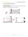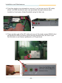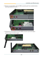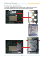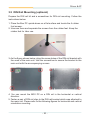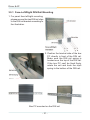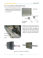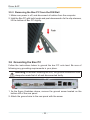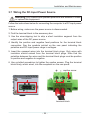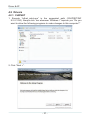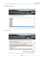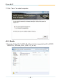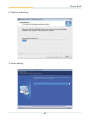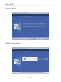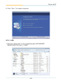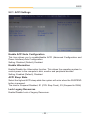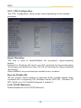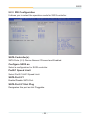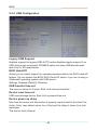
1
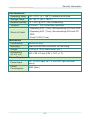
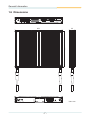
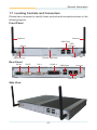
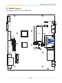
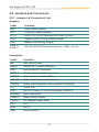
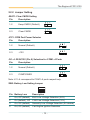
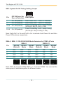
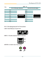
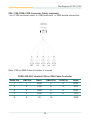
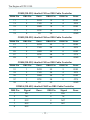
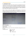
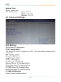
FPC-3130
Robust Box PC with
Intel Atom™ D2550 Platform
®
User’s Manual
Version 1.0
P/N: 4012313000100P
2012.06
This page is intentionally left blank.
-2-
Index
Contents
Chapter 1 - General Information................................................................... 1
1.1 Introduction................................................................................... 2
1.2 Packing List................................................................................... 3
1.3 Ordering Information.................................................................... 3
1.4 The Installation Paths of CD Driver............................................. 4
1.5 Specifications................................................................................ 5
1.6 Dimensions.................................................................................... 7
1.7 Locating Controls and Connectors............................................. 8
Chapter 2 - The Engine of FPC-3130............................................................ 9
2.1 Board Layout............................................................................... 10
2.2 Jumpers and Connectors........................................................... 11
2.2.1 Jumpers & Connectors List........................................... 11
2.2.2 Jumper Setting................................................................ 12
JBAT1: Clear CMOS Setting.......................................... 12
JCP1: COM Port Power Selector.................................. 12
JV1~4: RI/5V/12V Selection for COM1~4 Ports........... 12
SW2: Battery Low Setting Jumper............................... 12
SW1: System On/Off Timing Setting Jumper.............. 13
SW4~5, SW8~11: RS-232/422/485 Mode Selectors for
COM3~4 Ports................................................................ 13
2.2.3 Pin Assignments for Connectors.................................. 14
CN2: RS-232 (COM1~2); RS-232/422/485 (COM3~4)... 15
CBL-7100-COM (COM Converter Cable) (optional)..... 16
PWRIN1: DC Adapter Power Input............................... 18
DVI1: DVI-I....................................................................... 18
DVI2: DVI-D..................................................................... 18
Chapter 3 - Installation and Maintenance.................................................. 19
3.1 Memory, Mini-card & HDD Installation...................................... 20
3.1.1 Removing Top Cover...................................................... 20
3.1.2 Installing Memory Module.............................................. 21
3.1.3 Installing Mini-card (optional)........................................ 22
3.1.4 Installing Hard Disk Drive............................................... 25
3.2 How to Access CFast/SIM Card................................................. 26
3.3 Wall Mounting (optional)............................................................ 27
3.4 VESA Mounting (Optional)......................................................... 28
3.5 DIN Rail Mounting (optional)...................................................... 30
3.5.1 Face-Left/Right DIN Rail Mounting................................ 31
3.5.2 Face-Up/Down DIN Rail Mounting................................. 32
3.5.3 Removing the Box PC from the DIN Rail...................... 33
-I-
Index
3.6 Grounding the Box PC................................................................ 33
3.7 Wiring the DC-Input Power Source........................................... 34
Chapter 4 - Driver & AP............................................................................... 35
4.1 Preliminary work......................................................................... 36
4.2 Drivers.......................................................................................... 37
4.2.1 CHIPSET........................................................................... 37
4.2.2 VGA.................................................................................. 40
4.2.3 Audio................................................................................ 43
4.2.4 LAN................................................................................... 46
Chapter 5 - BIOS.......................................................................................... 49
5.1 BIOS Main Setup......................................................................... 50
5.2 Advanced Settings...................................................................... 51
5.2.1 ACPI Settings.................................................................. 52
5.2.2 CPU Configuration.......................................................... 53
5.2.3 IDE Configuration............................................................ 54
5.2.4 USB Configuration.......................................................... 55
5.2.5 Second Super IO Configuration..................................... 56
5.2.6 F71869 Super IO Configuration..................................... 57
5.2.7 F71869 H/W Monitor........................................................ 57
5.3 Chipset Settings........................................................................... 58
5.3.1 Host Bridge...................................................................... 58
5.3.2 South Bridge.................................................................... 60
5.4 Boot Settings............................................................................... 63
5.5 Security........................................................................................ 64
5.6 Save & Exit................................................................................... 65
Appendix...................................................................................................... 67
Watchdog Timer (WDT) Setting........................................................ 68
- II -
Copyright Notice
All Rights Reserved.
The information in this document is subject to change without prior notice in
order to improve the reliability, design and function. It does not represent a
commitment on the part of the manufacturer.
Under no circumstances will the manufacturer be liable for any direct, indirect,
special, incidental, or consequential damages arising from the use or inability
to use the product or documentation, even if advised of the possibility of such
damages.
This document contains proprietary information protected by copyright. All
rights are reserved. No part of this document may be reproduced by any mechanical, electronic, or other means in any form without prior written permission of the manufacturer.
Declaration of Conformity
CE
The CE symbol on your product indicates that it is in compliance with the directives of the Union European (EU). A Certificate of Compliance is available
by contacting Technical Support.
This product has passed the CE test for environmental specifications when
shielded cables are used for external wiring. We recommend the use of
shielded cables. This kind of cable is available from ARBOR. Please contact
your local supplier for ordering information.
This product has passed the CE test for environmental specifications when
shielded cables are used for external wiring. We recommend the use of
shielded cables. This kind of cable is available from ARBOR. Please contact
your local supplier for ordering information.
Warning
This is a class A product. In a domestic environment this product may cause
radio interference in which case the user may be required to take adequate
measures.
FCC Class B
This device complies with Part 15 of the FCC Rules. Operation is subject to
the following two conditions:
(1)This device may not cause harmful interference, and
(2)This device must accept any interference received, including interference
that may cause undesired operation.
NOTE:
This equipment has been tested and found to comply with the limits for a
-i-
Class B digital device, pursuant to Part 15 of the FCC Rules. These limits
are designed to provide reasonable protection against harmful interference
in a residential installation. This equipment generates, uses and can radiate
radio frequency energy and, if not installed and used in accordance with the
instructions, may cause harmful interference to radio communications. However, there is no guarantee that interference will not occur in a particular installation. If this equipment does cause harmful interference to radio or television
reception, which can be determined by turning the equipment off and on, the
user is encouraged to try to correct the interference by one or more of the following measures:
-- Reorient or relocate the receiving antenna.
-- Increase the separation between the equipment and receiver.
-- Connect the equipment into an outlet on a circuit different from that to
which the receiver is connected.
-- Consult the dealer or an experienced radio/TV technician for help.
RoHS
ARBOR Technology Corp. certifies that all components in its products are in
compliance and conform to the European Union’s Restriction of Use of Hazardous Substances in Electrical and Electronic Equipment (RoHS) Directive
2002/95/EC.
The above mentioned directive was published on 2/13/2003. The main purpose of the directive is to prohibit the use of lead, mercury, cadmium, hexavalent chromium, polybrominated biphenyls (PBB), and polybrominated diphenyl ethers (PBDE) in electrical and electronic products. Member states of the
EU are to enforce by 7/1/2006.
ARBOR Technology Corp. hereby states that the listed products do not contain unintentional additions of lead, mercury, hex chrome, PBB or PBDB that
exceed a maximum concentration value of 0.1% by weight or for cadmium
exceed 0.01% by weight, per homogenous material. Homogenous material
is defined as a substance or mixture of substances with uniform composition
(such as solders, resins, plating, etc.). Lead-free solder is used for all terminations (Sn(96-96.5%), Ag(3.0-3.5%) and Cu(0.5%)).
SVHC / REACH
To minimize the environmental impact and take more responsibility to the
earth we live, Arbor hereby confirms all products comply with the restriction of
SVHC (Substances of Very High Concern) in (EC) 1907/2006 (REACH --Registration, Evaluation, Authorization, and Restriction of Chemicals) regulated
by the European Union.
All substances listed in SVHC < 0.1 % by weight (1000 ppm)
- ii -
Important Safety Instructions
Read these safety instructions carefully
1. Read all cautions and warnings on the equipment.
2. Place this equipment on a reliable surface when installing. Dropping it or
letting it fall may cause damage
3. Make sure the correct voltage is connected to the equipment.
4. For pluggable equipment, the socket outlet should be near the equipment
and should be easily accessible.
5. Keep this equipment away from humidity.
6. The openings on the enclosure are for air convection and protect the equipment
from overheating. DO NOT COVER THE OPENINGS.
7. Position the power cord so that people cannot step on it. Do not place
anything over the power cord.
8. Never pour any liquid into opening. This may cause fire or electrical
shock.
9. Never open the equipment. For safety reasons, the equipment should be
opened only by qualified service personnel.
10. If one of the following situations arises, get the equipment checked by
service personnel:
a. The power cord or plug is damaged.
b. Liquid has penetrated into the equipment.
c. The equipment has been exposed to moisture.
d. The equipment does not work well, or you cannot get it to work according
to the user’s manual.
e. The equipment has been dropped or damaged.
f. The equipment has obvious signs of breakage.
11. Keep this User’s Manual for later reference.
- iii -
About This User’s Manual
This User’s Manual is intended for experienced users and integrators with
hardware knowledge of personal computers. If you are not sure about any
description in this User’s Manual, please consult your vendor before further
handling.
Warning
The Box PC and its components contain very delicately Integrated Circuits
(IC). To protect the Box PC and its components against damage caused by
static electricity, you should always follow the precautions below when handling it:
1. Disconnect your Box PC from the power source when you want to work on
the inside.
2. Use a grounded wrist strap when handling computer components.
3. Place components on a grounded antistatic pad or on the bag that came
with the Box PC, whenever components are separated from the system.
Replacing the Lithium Battery
Incorrect replacement of the lithium battery may lead to a risk of explosion.
The lithium battery must be replaced with an identical battery or a battery type
recommended by the manufacturer.
Do not throw lithium batteries into the trashcan. It must be disposed of in
accordance with local regulations concerning special waste.
Technical Support
If you have any technical difficulties, please consult the user’s manual first
at: ftp://ftp.arbor.com.tw/pub/manual
Please do not hesitate to call or e-mail our customer service when you still cannot find out the answer.
http://www.arbor.com.tw
E-mail:[email protected]
- iv -
Warranty
This product is warranted to be in good working order for a period of one year
from the date of purchase. Should this product fail to be in good working order
at any time during this period, we will, at our option, replace or repair it at no
additional charge except as set forth in the following terms. This warranty does
not apply to products damaged by misuse, modifications, accident or disaster.
Vendor assumes no liability for any damages, lost profits, lost savings or any
other incidental or consequential damage resulting from the use, misuse of, or
inability to use this product. Vendor will not be liable for any claim made by any
other related party.
Vendors disclaim all other warranties, either expressed or implied, including but
not limited to implied warranties of merchantability and fitness for a particular
purpose, with respect to the hardware, the accompanying product’s manual(s)
and written materials, and any accompanying hardware. This limited warranty
gives you specific legal rights.
Return authorization must be obtained from the vendor before returned merchandise will be accepted. Authorization can be obtained by calling or faxing
the vendor and requesting a Return Merchandise Authorization (RMA) number.
Returned goods should always be accompanied by a clear problem description.
-v-
This page is intentionally left blank.
- vi -
General Information
1
Chapter 1
General Information
-1-
General Information
1.1 Introduction
The Box PC, FPC-3130 is targeted at many different application fields. By
adopting it, you can pinpoint specific markets, such as Thin Client, KIOSK,
information booth, GSM Server, environment-critical and space-critical
applications.
•
•
•
•
•
•
•
All-In-One Platform
The CPU, DRAM and even software are integrated to provide a plugand-play machine.
Compact-sized
The kernel of FPC-3130 is FMB-i2505, which is a non-standard form
factor embedded board. The whole system consumes only a few
space.
Fanless and Modular CPU Board
By using a low power processor, the system does not have to rely on
fans, which are often unreliable and cause dust to circulate inside the
equipment. The modular design facilitates maintenance or possible
upgrades on the CPU board. Modular Box PC can be easily modified
to fit many different applications according to customers' requests.
Powerful Communication Capability
The FPC-3130 provides COM, Ethernet, USB, Mini Card slot, CFast,
SIM and DVI.
Numerous Display/Video Output
Integrated with Intel® HD Graphics core, FPC-3130 improves graphics
and 3D rendering performance and supports display/video output
options includes DVI-I and DVI-D.
Advanced Storage Solution
FPC-3130 comes with SD (Secure Digital) slot, which offers a better,
faster and more cost-effective expansibilities for various applications.
Trustworthy
The onboard Watchdog Timer can invoke an NMI or system RESET
when your application loses control over the system.
-2-
General Information
1.2 Packing List
After opening the package, carefully inspect the contents. If any of the items
is missing or appears damaged, please contact your local dealer or distributor.
The package should contain the following items:
1 x FPC-3130 Box PC
1 x Driver CD
1 x User’s Manual
1.3 Ordering Information
FPC-3130
Barebone system w/o storage device
The following items are normally optional, but some vendors may include
them as a standard package, or some vendors may not carry all the items.
Optional Accessories
PAC-B065W-1
65W AC/DC adapter kit
DRK-001
Din rail kit of FPC series
WMK-3100
Wall-mount kit
-3-
General Information
VMK-3100
VESA mount kit
CBL-7100-COM
COM converter cable
Optional Configuration (Configure to Order Service)
SSD-25040
Intel® 2.5” 40GB SATAII SSD kit
MM-3C-2G
DDR3-1333 2GB SDRAM
MM-3C-4G
DDR3-1333 4GB SDRAM
WFM-i2030
802.11 a/b/g/n WiFi module kit & internal wiring
ANT-11
1 x WiFi Dual-band 2.4G/5G antenna
1.4 The Installation Paths of CD Driver
Windows 7-32bit
Driver
Path
CHIPSET
\Chipset\Win7_x86
VGA
\VGA\Win7_x86
LAN
\LAN\Install_Win7_7048_09162011
AUDIO
\Driver\Audio ALC662\Win 7(32,64 bits) Driver_R2.66
Note: FPC-3130 only supports Windows 7 32bit.
-4-
General Information
1.5 Specifications
System Kernel
Processor
Soldered onboard Intel® Atom™ D2550 1.86GHz
processor
BIOS
AMI Flash BIOS
Chipset
Intel® NM10 PCH
Graphics
Integrated Intel® GMA 3650
System Memory
1 x 204-pin Dual Channels DDR3 SO-DIMM Socket
up to 4GB at 800/1066MHz
Serial ATA
1 x Serial ATA port with 300MB/s HDD transfer rate
Ethernet Controller 2 x Realtek 8111 Gigabit Ethernet controllers
Watchdog Timer
1 ~ 255 levels reset
I/O Ports
Serial Port
2 x RS-232 ports & 2 x RS-232/422/485 selectable
ports with DB-44 pin connector
Expansion Bus
• 1 x Mini-card slot interconnected with SIM card
socket for optional WiFi or HSUPA module
• 1 x SIM Card Socket
USB Port
6 x USB 2.0 ports
LAN
2 x RJ-45 ports for Gigabit Ethernet
Video Port
• 1 x DVI-I female connector for Digital Video output
• 1 x DVI-D female connector for Digital Video output
Audio
Mic-in/Line-out/Line-out with 6W amplify
Storage
Type
• 1 x 2.5” drive bay for HDD/SSD
• 1 x CFast Socket
Qualification
FCC
Class B certified
CE
Certified
-5-
General Information
Environmental
Operating Temp.
-20 ~ 70°C (-4 ~ 158°F), ambient w/ air flow
Storage Temp.
-40 ~85 °C (-40 ~ 185°F)
Relative Humidity
10 ~ 95% @ 40oC (non-condensing)
Vibration
3 Grms/5 ~ 500 Hz/random operation
Shock & Crash
• Operating 20G (11ms), Non-operating 60G with HDD
• Operating 40G (11ms), Non-operating 80G with CF/
SSD
• Crash 100G (11ms)
Mechanical
Construction
Aluminum alloy
Mounting
Wall-mount/VESA-mount/Din rail mounting
Weight
1.89 kg (4.16 lb) (Bare-bone) (ref.)
Dimensions
(W x D x H)
252 x 199 x 33 mm (9.92” x 7.83” x 1.3”)
Power Requirement
Power Input
DC 10~28V input (w/ 1 x 3-pin DC input terminal
block)
Power
Consumption
30W (Max.)
-6-
General Information
1.6 Dimensions
252
33
199
Unit: mm
-7-
General Information
1.7 Locating Controls and Connectors
Please take a moment to identify those controls and connectors shown in the
following figures.
Front Panel
Antenna
Antenna
USB Ports
HDD
Indicator
MIC-in
Switch
CFast & SIM Slots
Earphone-out
Rear Panel
DC-IN
DVI-D
DVI-I
COM1-4
USB Ports
Line-out
LAN Ports
Side View
-8-
The Engine of FPC-3130
2
Chapter 2
The Engine of
FPC-3130
-9-
The Engine of FPC-3130
2.1 Board Layout
PWRIN1
The engine of FPC-3130 is FMB-i2505.
PWRBT1
1
6
USB2
2
1
1
DVI2
HDDLED
8
71
72
73
74
USB3
S1
JV1
JV2
JV3
JV4
JCP1
CF1
SIM1
SW2
ON
6
PC17
1
DIP
7
12
ON
SW1
1
1 2 3 4 5 6 7 8
SW10 SW9
1 2 3 4 5 6 7 8
9
16
ON
9
ON
52
16
16 18
CN2
1 2 3 4 5 6
SW8 SW5
4
JBAT1
1
4
1 2 3 4
1
1
1
1
SW1 SW4
1
4
2 3
2
2 3
51
1
PC1
17
2 3
4
204
2 3
1
203
ON
15
1
S7
ON
1
DVI1
DIMM2
P15
MC1
SATA0
P1
MH2
S7
MH1
USB1
AUDIO2
S1
LAN1
AUDIO3
AUDIO4
- 10 -
The Engine of FPC-3130
2.2 Jumpers and Connectors
2.2.1 Jumpers & Connectors List
Jumpers
Label
Function
JBAT1
Clear CMOS Setting
JCP1
COM Port Power Selector
JV1~4
RI/5V/12V (Pin 9) Selectors for COM1~4 Ports
SW1
System On/Off Timing Setting Jumper
SW2
Battery Low Setting Jumper
SW4~5,
SW8~11
RS-232/422/485 Mode Selectors for COM3~4 Ports
Connectors
Label
Function
MC1
Mini Card Socket
SATA0
Serial ATA + Power Connector
LAN1
Dual Ethernet Connectors
USB1~3
Double-stacked USB Connectors
AUDIO2
Audio Jack Connector (MIC)
AUDIO3
Audio Jack Connector (Line-out)
AUDIO4
Audio Jack Connector (Line-out with 6W Amplify)
CF1
CFast Slot
CN2
RS-232 (COM1~2); RS-232/422/485 (COM3~4)
HDDLED
HDD Status LED
PWRBT1
Power On/Off Switch
PWRIN1
DC Adapter Power Input
DVI1
DVI-I
DVI2
DVI-D
SIM1
SIM Card Slot
- 11 -
The Engine of FPC-3130
2.2.2 Jumper Setting
JBAT1: Clear CMOS Setting
Pin
Description
1-2
Keep CMOS (Default)
2-3
Clear CMOS
3
2
1
3
2
1
JCP1: COM Port Power Selector
Pin
Description
1-2
Normal (Default)
2-3
+12V
3
2
1
3
2
1
3
2
1
3
2
1
JV1~4: RI/5V/12V (Pin 9) Selection for COM1~4 Ports
Pin
Description
1-2
Normal (Default)
2-3
COMPOWER
Note: JV1~4 correspond to COM1~4 ports respectively.
SW2: Battery Low Setting Jumper
ON
DIP
1 2 3 4
Pin Battery Low
Description
1
On, Off (default)
BUS Low Voltage Detection (24V)
2
On (default), Off
CAR Low Voltage Detection (12V)
3
On, Off (default)
Normally Low Voltage Detection (9V above)
4
On, Off (default)
Car Engine Ignition Detection
- 12 -
The Engine of FPC-3130
SW1: System On/Off Timing Setting Jumper
ON
DIP
1 2 3 4 5 6
Pin
DIP SW Auto Car
Description
Key on Detection
1
On, Off (default)
2
On, Off (default)
Auto Power Off (1 - Auto / 0 - Manual)
3&4
On, Off (default)
Power-on Waiting Time – Setup Timing
(00-4s)(01-8s)(10-12s)(11-16s)
5&6
On, Off (default)
Power-off Waiting Time – Setup Timing
(00-30s)(01-45s)(10-60s)(11-90s)
Auto Power On (1 - Auto / 0 - Manual)
Note: Swith Pin1 to On and Pin2 to On to activate Auto Power On and Auto
Power Off functions respectively.
SW4~5, SW8~11: RS-232/422/485 Mode Selectors for COM3~4 Ports
SW4~5
SW8 & 11
Pin
RS-232
(Default)
RS-422
Mode
RS-485
Mode
1
ON
OFF
OFF
2
OFF
ON
OFF
3
OFF
OFF
ON
4
ON
OFF
OFF
ON
ON
ON
KE
KEKE
11 122 233 344 4
ON
ON
ON
KE
KEKE
ON
ON
ON
KE
KEKE
11 122 233 344 4
ON
ON
ON
KE
KEKE
ON
ON
ON
OFF
OFF
KE
KEKE
11 122 233 344 4
ON
ON
ON
ON
RS-485
Mode
ON
ON
KE
KEKE
11 122 233 344 4
OFF
ON
ON
KE
KEKE ON
RS-422
Mode
ON
OFF
ON
ON
ON
11 122 233 344 4
ON
ON
ON
RS-232
(Default)
ON
KE
KEKE
ON
ON
ON
OFF
KE
KEKE
11 122 233 344 4
11 122 233 344 4
ON
OFF
ON
ON
ON
KE
KEKE
11 122 233 344 4
ON
ON
ON
KE
KEKE
11 122 233 344 4
KE
KEKE
Note: SW4, 8, 9 control COM3; SW5, 11, 10 control COM4. You must set the
same group11 1of
switches11 together
for11 1different
modes.
22 233 344 4
122 233 344 4
22 233 344 4
- 13 -
The Engine of FPC-3130
SW9~10
Pin
RS-232 Mode (Default)
RS-422/RS-485 Mode
1
ON
OFF
2
ON
OFF
3
ON
OFF
1
4
ON
OFF
ON
5
ON
1
6
ON
ON
7
ON
8
ON
ON
1
KE
2
2
3
3
4
4
5
5
6
6
7
7
8
OFF
KE
OFF
8
OFF
OFF
2.2.3 Pin Assignments for Connectors
LAN1: Dual Ethernet Connectors
USB1~3: Double-stacked USB Connectors
1 2 3 4
USB
1 2 3 4
USB
AUDIO2~4: Audio Jack Connectors
- 14 -
KE
ON
1
2
3
4
5
6
7
8
KE
2
3
4
5
6
7
8
The Engine of FPC-3130
CN2: RS-232 (COM1~2); RS-232/422/485 (COM3~4)
1
15
44
31
Pin
Desc.
Pin
Desc.
Pin
Desc.
Pin
Desc.
1
DCD
2
RXD
11
DCD
12
RXD
3
TXD
4
DTR
TXD
14
DTR
5
GND
6
DSR
13
COM2 15
(RS-232)
GND
16
DSR
7
RTS
8
CST
17
RTS
18
CST
9
RI
10
GND
19
RI
20
GND
21
DCD
22
RXD
31
DCD
32
RXD
23
COM3 25
(RS-232)
TXD
24
DTR
TXD
34
DTR
GND
26
DSR
33
COM4 35
(RS-232)
GND
36
DSR
27
RTS
28
CST
37
RTS
38
CST
29
RI
30
GND
39
RI
40
GND
41
N/C
42
N/C
43
N/C
44
N/C
COM1
(RS-232)
N/C
- 15 -
The Engine of FPC-3130
CBL-7100-COM (COM Converter Cable) (optional)
1 to 5 COM converter cable: 4 x DB9 male and 1 x DB9 female connectors
CN4
CN6
CN2
CN5
CN3
Note: CN6 on DB9 Cable Controller is unused.
COM1 (RS-232) labelled CN2 on DB9 Cable Controller
DB44 Pin
DB9 Pin
Desc.
DB44 Pin
DB9 Pin
Desc.
1
1
DCD
2
2
RXD
3
3
TXD
4
4
DTR
5
5
GND
6
6
DSR
7
7
RTS
8
8
CTS
9
9
RI
10
- 16 -
GND
The Engine of FPC-3130
COM2 (RS-232) labelled CN3 on DB9 Cable Controller
DB44 Pin
DB9 Pin
Desc.
DB44 Pin
DB9 Pin
Desc.
11
1
DCD
12
2
RXD
13
3
TXD
14
4
DTR
15
5
GND
16
6
DSR
17
7
RTS
18
8
CTS
19
9
RI
20
GND
COM3 (RS-232) labelled CN4 on DB9 Cable Controller
DB44 Pin
DB9 Pin
Desc.
DB44 Pin
DB9 Pin
Desc.
21
1
DCD
22
2
RXD
23
3
TXD
24
4
DTR
25
5
GND
26
6
DSR
27
7
RTS
28
8
CTS
29
9
RI
30
GND
COM4 (RS-232) labelled CN5 on DB9 Cable Controller
DB44 Pin
DB9 Pin
Desc.
DB44 Pin
DB9 Pin
Desc.
31
1
DCD
32
2
RXD
33
3
TXD
34
4
DTR
35
5
GND
36
6
DSR
37
7
RTS
38
8
CTS
39
9
RI
40
GND
COM3/4 (RS-422) labelled CN4/5 on DB9 Cable Controller
DB9 Pin
Signal
1
Desc.
DB9 Pin
Signal
Rx-
2
Rx+
3
Tx+
4
Tx-
5
N/C
6
N/C
7
N/C
8
N/C
9
N/C
- 17 -
Desc.
The Engine of FPC-3130
COM3/4 (RS-485) labelled CN4/5 on DB9 Cable Controller
DB9 Pin
Signal
1
Desc.
DB9 Pin
Signal
DATA-
2
DATA+
3
N/C
4
N/C
5
N/C
6
N/C
7
N/C
8
N/C
9
N/C
PWRIN1: DC Adapter Power Input
Pin
Description
1
VCC 10~28V
2
GND
3
ACC (ignition signal)
1 2 3
VCC GND Acc
DVI1: DVI-I
DVI2: DVI-D
- 18 -
Desc.
Installation and Maintenance
3
Chapter 3
Installation and
Maintenance
- 19 -
Installation and Maintenance
3.1 Memory, Mini-card & HDD Installation
FPC-3130 is designed to be modular, slim and lightweight for easier
maintenance. The following sections describe simple hardware installations.
3.1.1 Removing Top Cover
1. Carefully place the Box PC on flat surface. Unscrew four screws securing
the top cover. Remove top cover using a crosshead from the notch on rear
panel's edge. Rember, top cover adheres to internal parts thightly due to a
sticky thermal pad, so you should unclinch it by some force.
2. Gently pull top cover upward and retain it for later use.
Mini-card
Socket
Memory
Socket
Drive Bay
- 20 -
Installation and Maintenance
3.1.2 Installing Memory Module
Side notch
Latch knob
Latch claw
Latch section
Latch arm
Polarizing key
Key
To install the Memory module, locate the Memory SO-DIMM slot on the
board and perform as below:
1. Adjust the socket polarizing key and the board key to the same direction.
2. Insert the board obliquely. Moreover, lay the board in parallel to the
opening at angle of 20o to 30o, and softly insert the board so as to hit the
socket bottom. Stopping insertion halfway will result in improper insertion.
3. Applying the board side notch in parallel to the socket bottom so that
the board position cannot be displaced, press the board side notch up,
and fix it to the latch portion at both socket edges. Press the board side
notch, and release the notch with a snap “click” tone, if the printed board
exceeds the latch claw head.
1
2
3
Procedures for board extraction
Apply the thumb nail to the latch knob at both socket edges. Forcibly widen
the latch knobs to right and left ways, and release the latch. Then draw the
board out along an angle where the board is raised.
- 21 -
Installation and Maintenance
3.1.3 Installing Mini-card (optional)
1. Locate Mini-card socket.
2. Insert HSUPA module into its slot at a slanted angle. Remember to align the
notch with the break on slot.
3. And then, secure two screws to fasten the module.
1
3
2
- 22 -
Installation and Maintenance
4. Push the plastic plug outwards to remove it, so that one end of RF cable,
which is a SMA connector jack, can penetrate through antenna hole
located on front pane. Keep the plastic plug for later use.
5. Press another end of the RF cable into one of the studs named MAIN. And
penetrate the SMA connector jack through antenna hole, be sure to put
the flat side (in red frame) rightwards, or it'll get stuck.
Align the flat fitting side
with the red flat edge of
antenna hole.
- 23 -
Installation and Maintenance
6. Mount a round washer into the SMA connector jack from outside before
securing another nut into it.
7. At the end, screw antenna into the SMA connector jack and adjust
antenna angle for better signal.
- 24 -
Installation and Maintenance
3.1.4 Installing Hard Disk Drive
1. Unscrew HDD bracket from the main board. Fasten HDD on bracket.
2. Insert the bracket into driver bay and secure its four corners.
- 25 -
Installation and Maintenance
3.2 How to Access CFast/SIM Card
1. Make sure you have turned off the power before inserting or ejecting the
CFast card (if OS is installed on CFast card).
2. Locate the CFast card door on the front panel.
3. Use a crosshead screwdriver (#1 tip) to remove the screw that secures
the CFast/SIM card door. Pull down the door. Owning to mechanical design, please move left first and right while pulling off.
4. Insert your CFast/SIM card into the slot according to the illustration by the
card holder. Push it inward until you hear a click. After inserting the CFast/
SIM card, close the card door and screw it on clockwise.
5. To remove the CFast/SIM card, follow step 1, 2 and 3 above. And then
push card inward to pop-out it from the slot.
- 26 -
Installation and Maintenance
3.3 Wall Mounting (optional)
Prepare the wall-mount bracket and a screwdriver for wall mounting. Follow
the instructions below:
1. Place the Box PC upside down on a flat surface and locate the 4 rubber
foot screws.
2. Unscrew them and separate the screws from the rubber feet. Keep the
rubber feet for later use.
3. Use the screws to secure the wall-mount bracket to the unit.
4. When the bracket is attached, the computer can be hanged on the wall as
the way you want.
- 27 -
Installation and Maintenance
3.4 VESA Mounting (Optional)
FPC-3130 can be mounted to the rear side of the LCD monitor that is VESA
75/100 compliant. To mount FPC-3130 to your monitor, please prepare the
wall-mount bracket, VESA-mount brackets, accompanying screws and a
screwdriver. Please follow the instructions as below:
1. Locate the VESA-compliant screw holes at the rear side of the LCD monitor.
2. Secure the VESA mounting brackets firmly to the monitor.
- 28 -
Driver & AP
3. With the wall-mount bracket attached, slide FPC-3130 onto the VESA
bracket. When the computer is well seated, secure it to the VESA bracket
with the accompanying screws. See the figures shown below.
- 29 -
Driver & AP
3.5 DIN Rail Mounting (optional)
Prepare the DIN rail kit and a screwdriver for DIN rail mounting. Follow the
instructions below:
1. Place the Box PC upside down on a flat surface and locate the 4 rubber
foot screws.
2. Unscrew them and separate the screws from the rubber feet. Keep the
rubber feet for later use.
3. As the figure shown below, align the screw holes of the DIN rail bracket with
the ones of the main unit. Use the screwdriver to secure the bracket to the
main unit with the accompanying screws.
4. You can mount the BOX PC on a DIN rail in the horizontal or vertical
direction.
5. Fasten a pair of DIN rail clips to the DIN rail bracket which was attached to
the main unit. Please refer to the following figures for horizontal and vertical
orientation mounting.
- 30 -
Driver & AP
3.5.1 Face-Left/Right DIN Rail Mounting
1. For panel face-left/right mounting,
please secure the two DIN rail clips
to the DIN rail bracket according to
the illustration.
2. Position the bracket side of the box
PC directly in front of the DIN rail.
Make sure the DIN rail spring is
hooked over the top of the DIN rail.
If the box PC can’t be fixed firmly,
rotate the unit and hook the clip’s
spring to the bottom of the DIN rail.
Box PC mounted on the DIN rail
- 31 -
Driver & AP
3.5.2 Face-Up/Down DIN Rail Mounting
1. For panel face-up/down mounting,
please secure the two DIN rail clips
to the DIN rail bracket according to
the illustration.
2. Position the bracket side of the box
PC directly in front of the DIN rail.
Make sure the DIN rail spring is
hooked over the top of the DIN rail.
If the box PC can’t be fixed firmly,
rotate the unit and hook the clip’s
spring to the bottom of the DIN rail.
Box PC mounted on the DIN rail
- 32 -
Driver & AP
3.5.3 Removing the Box PC from the DIN Rail
1. Make sure power is off, and disconnect all cables from the computer.
2. Hold the Box PC with both hands and push downwards. As the clip releases,
lift the bottom of Box PC slightly.
3.6 Grounding the Box PC
Follow the instructions below to ground the box PC onto land. Be sure of
following any grounding requirements in your place.
Warning Whenever installing the unit, the ground connection must
always be made first of all and disconnected lastly.
1. As the figure illustrates above, remove the ground screw located on the
bottom-left of the rear panel.
2. Attach the ground wire to the rear panel with the screw.
- 33 -
Installation and Maintenance
3.7 Wiring the DC-Input Power Source
Warning Only trained and qualified personnel are allowed to install
or replace this equipment.
Follow the instructions below for connecting the computer to a DC-input power
source.
1. Before wiring, make sure the power source is disconnected.
2. Find the terminal block in the accessory box.
3. Use the wire-stripping tool to strip a short insulation segment from the
output wires of the DC power source.
4. Identify the positive and negative feed positions for the terminal block
connection. See the symbols printed on the rear panel indicating the
polarities and DC-input power range in voltages.
5. Insert the exposed wires into the terminal block plugs. Only wires with
insulation should extend from the terminal block plugs. Note that the
polarities between the wires and the terminal block plugs must be positive
to positive and negative to negative.
6. Use a slotted screwdriver to tighten the captive screws. Plug the terminal
block firmly, which wired, into the receptacle on the rear panel.
+ -
captive screw
receptacle
DC-IN
+terminal block
- 34 -
Driver & AP
4
Chapter 4
Driver & AP
- 35 -
Driver & AP
4.1 Preliminary work
After everything mentioned before is settled down, and now, you need
to install the necessary drivers and the application so that the box PC’s
functions can operate normally. The following instructions take Windows
7 as the exemplary OS. Different OS may vary slightly, but generally
speaking, they are almost the same. Be assured that appropriate installation procedure is as below:
CHIPSET→VGA→AUDIO→LAN
Please Follow This Procedure to install all necessary units in most cases, or you may encounter errors.
Also, the correct driver & AP paths for Windows 7 & Windows XP are
listed below. You should follow the suggested paths to proceed with installation.
Windows 7-32bit
Driver
Path
CHIPSET
\Chipset\Win7_x86
VGA
\VGA\Win7_x86
LAN
\LAN\Install_Win7_7048_09162011
AUDIO
\Driver\Audio ALC662\Win 7(32,64 bits) Driver_R2.66
Note: FPC-3130 only supports Windows 7 32bit.
- 36 -
Driver & AP
4.2 Drivers
4.2.1 CHIPSET
1. Execute “infinst_autol.exe” in the suggested path (\CHIPSET\INF
9.2.0.1030). Always click Yes whenever Windows 7 inquires you “Do you
want to allow the following programs to make changes to this computer?”
2. Click “Next >”.
- 37 -
Driver & AP
3. Wait for extracting.
4. Click “Yes >”.
- 38 -
Driver & AP
5. Click “Next >”.
6. Click “Finish >”.
- 39 -
Driver & AP
4.2.2 VGA
1. Execute “Setup.exe” in the suggested path (\GRAPHICS\INTEL_
WIN7_32\2230).
2. Click “Next >”.
- 40 -
Driver & AP
3. Click “Yes >”.
4. Click “Next >”.
- 41 -
Driver & AP
5. Wait for the process.
6. Click “Next >”.
- 42 -
Driver & AP
7. Click “Yes >” to restart computer.
4.2.3 Audio
1. Execute “Vista_Win7_R261-32_64.exe” in the suggested path (\AUDIO\
REALTEK_HD\Vista_Win7_R261-32_64 bit).
- 43 -
Driver & AP
2. Wait for extracting.
3. Keep waiting.
- 44 -
Driver & AP
4. Click “Next >”.
5. Wait for the process.
- 45 -
Driver & AP
6. Click “Yes >” to restart computer.
4.2.4 LAN
1. Execute “setup.exe” in the suggested path (\ETHERNET\
REALTEK\8111B_Win7_7046).
- 46 -
Driver & AP
2. Click “Next >”.
3. Click “Install >”.
- 47 -
Driver & AP
4. Wait for the process.
5. Click “Finish >”.
- 48 -
BIOS
5
Chapter 5
BIOS
- 49 -
BIOS
5.1 BIOS Main Setup
The AMI BIOS provides a setup utility program for specifying the system
configurations and settings which are stored in the BIOS ROM of the system.
When you turn on the computer, the AMI BIOS is immediately activated. After
you have entered the setup utility, use the left/right arrow keys to highlight a
particular configuration screen from the top menu bar or use the down arrow
key to access and configure the information below.
Note: In order to increase system stability and performance, our engineering
staff are constantly improving the BIOS menu. The BIOS setup screens and
descriptions illustrated in this manual are for your reference only, and may not
completely match what you see on your screen.
BIOS Information
Display the BIOS information.
System Date
Set the system date. Note that the ‘Day’ automatically changes when you set
the date.
The date format is:
Day : Sun to Sat
Month : 1 to 12
Date : 1 to 31
Year : 1999 to 2099
- 50 -
BIOS
System Time
Set the system time.
Hour : 00 to 23
The time format is:
Minute : 00 to 59
Second : 00 to 59
5.2 Advanced Settings
ACPI Settings
Set system ACPI parameters.
CPU Configuration
This section is used to configure the CPU. It will also display detected CPU
information.
IDE Configuration
Configure IDE devices.
USB Configuration
Configure the USB devices.
Second Super IO Configuration
Set system super IO chip parameters.
F71869 Super IO Configuration
Set system super IO chip parameters.
F71869 H/W Monitor
Reveal monitor hardware status.
- 51 -
BIOS
5.2.1 ACPI Settings
Enable ACPI Auto Configuration
This item allows you to enable/disable ACPI (Advanced Configuration and
Power Interface) Auto Configuration.
Setting: Disabled (Default), Enabled.
Enable Hibernation
Enable/Disable the Hibernation function. This allows the operating system to
control power to the computer’s disk, monitor and peripheral devices.
Setting: Enabled (Default), Disabled
ACPI Sleep State
Select the highest ACPI sleep state the system will enter when the SUSPEND
button is pressed.
The choice: Suspend Disabled, S1 (CPU Stop Clock), S3 (Suspend to RAM)
Lock Legacy Resources
Enable/Disable Lock of Legacy Resources.
- 52 -
BIOS
5.2.2 CPU Configuration
The CPU Configuration setup screen varies depending on the installed
processor.
Hyper-threading
This item is used to Enable/Disable the processor’s Hyper-threading
feature.
Enabled for Windows XP and Linux (OS optimized for Hyper-threading
Technology) and disabled for other OS (OS not optimized for Hyper-threading
Technology).
When disabled, only one thread per enabled core is enabled.
Execute Disable Bit
XD can prevent certain classes of malicious buffer overflow attacks when
combined with a supporting OS (Windows Server 2003 SP1, Windows XP
SP2, SuSE Linux 9.2, RedHat Enterprise 3 update 3.)
Limit CPUID Maximum
Enable/Disable the Limit CPUID Maximum.
- 53 -
BIOS
5.2.3 IDE Configuration
It allows you to select the operation mode for SATA controller.
SATA Controller(s)
SATA Ports (0-3) Device Names if Present and Enabled.
Configure SATA as
Select a configuration for SATA controller.
Port0/1 Speed Limit
Select Port0/1 AHCI Speed Limit.
SATA Port 0/1
Enable/Disable SATA Port.
SATA Port 0/1 Hot Plug
Designates this port as Hot Pluggable.
- 54 -
BIOS
5.2.4 USB Configuration
Legacy USB Support
Enables support for legacy USB. AUTO option disables legacy support if no
USB devices are connected. DISABLE option will keep USB devices available only for EFI applications.
EHCI Hand-Off
Allows you to enable support for operating systems without an EHCI hand-off
feature. Do not disable the BIOS EHCI Hand-Off option if you are running a
Windows® operating system with USB device.
Settings: Enabled (Default); Disabled
USB transfer time-out
The time-out value for Control, Bulk, and Interrupt transfers.
Device reset time-out
USB mass storage device Start Unit command time-out.
Device power-up delay
Max time the device will take before it properly reports itself to the Host Controller. ‘Auto’ uses default value: for a Root port the delay is taken from Hub
descriptor.
The choice: Auto, Manual
- 55 -
BIOS
5.2.5 Second Super IO Configuration
Serial Port 1~4 Configuration
Serial Port
This item allows you to enable/disable Serial Port (COM).
Change Settings
This item allows you to change the serial port IO port address and interrupt
address.
- 56 -
BIOS
5.2.6 F71869 Super IO Configuration
Power On After Power Fail
Specify what state to go to when power is re-applied after a power failure.
5.2.7 F71869 H/W Monitor
PC Health Status
The hardware monitor menu shows the operating temperature, fan speeds
and system voltages.
- 57 -
BIOS
5.3 Chipset Settings
This submenu allows you to configure the specific features of the chipset
installed on your system. The chipset manage bus speeds and access to
system memory resources, such as DRAM. It also coordinates communications
with the PCI bus.
Note: Beware of that setting inappropriate values in items of this menu may cause
system to malfunction.
5.3.1 Host Bridge
- 58 -
BIOS
Memory Frequency and Timing
MRC Fast Boot
Enable/Disable MRC fast boot.
Dyn SR
Enable/Disable Dyn SR.
Auto Disable IGD
Auto disable IGD upon external GFX detected.
IGFX - Boot Type
Select the Video Device which will be activated during POST. This has no effect if external graphics present.
- 59 -
BIOS
5.3.2 South Bridge
DMI Link ASPM Control
The control of Active State Power Management on both NB side and SB
side of the DMI Link.
PCI-Exp, High Priority Port
Select a PCI Express High Priority Port.
High Precision Timer
Enable/Disable the High Precision Event Timer.
SLP_S4 Assertion Width
Select a minimum assertion width of the SLP_S4# signal.
TPT Devices
- 60 -
BIOS
Azalia Controller
Enable/Disable Azalia Controller.
Azalia PME Enable
Enable/Disable Power Management capability of Audio Controller.
Azalia Vci Enable
Azalia supports 1 extended VC, which, when enabled, overrides ICH Vcp settings.
Select USB Mode
Select USB mode to control USB ports.
UHCI #1~4 (ports 0/2/4/6 and 1/3/5/7)
Control the USB UHCI (USB 1.1) functions. Disable from highest to lowest
controller.
USB 2.0(EHCI) Support
Enable/Disable USB 2.0(EHCI) Support.
LAN Controller
Enable/Disable OnChip NIC Controller.
SMBus Controller
Enable/Disable OnChip SMBus Controller.
SIRQ Logic
Enable/Disable SIRQ Logic.
SIRQ Mode
Set SIRQ Mode.
PCI Express Root Port 0~3
- 61 -
BIOS
PCI Express Port 0~3
Enable/Disable PCI Express Root Port 0~3.
Port 0~3 I/OxAPIC
Enable/Disable PCI Express Root Port 0~3 I/O APIC.
Automatic ASPM
Automatically enable ASPM based on reported capabilities and known issues.
The choice: Manual, Auto
URR
Enable/Disable PCI Express Unsupported Request Reporting.
FER
Enable/Disable PCI Express Device Fatal Error Reporting.
NFER
Enable/Disable PCI Express Device Non-Fatal Error Reporting.
CER
Enable/Disable PCI Express Device Correctable Error Reporting.
CTO
Enable/Disable PCI Express Completion Timer TO.
SEFE
Enable/Disable Root PCI Express System Error on Fatal Error.
SENFE
Enable/Disable Root PCI Express System Error on Non-Fatal Error.
SECE
Enable/Disable Root PCI Express System Error on Correctable Error.
PME SCI
Enable/Disable PCI Express PME SCI.
Hot Plug
Enable/Disable PCI Express Hot Plug.
- 62 -
BIOS
5.4 Boot Settings
The Boot menu items allow you to change the system boot options.
Bootup Numlock State
This item determines if the Numlock key is active or inactive at system
start-up time.
Quiet Boot
This allows you to select the screen display when the system boots.
Fast Boot
During the POST (Power On Self Test), the BIOS checks the hardware
devices and counts the system memory. But all of these system tests are
needed every time you boot, and can be turned off to save time. When set to
Enabled, this option shortens POST by eliminating some tests.
GateA20 Active
UPON REQUEST: GA20 can be disabled using BIOS services.
ALWAYS: disallow to disable GA20; this option is useful when any RT code is
executed above 1MB.
Fast Boot
Set display mode for Option ROM.
The choice: Force BIOS, Keep Current
Interrupt 19 Capture
Enable/Disable Option ROMs to trap Int 19.
- 63 -
BIOS
5.5 Security
Administrator Password
Use the Administrator Password to set or change a administrator password.
ENTER PASSWORD
Type the password, up to eight characters in length, and press <Enter>. The
password typed now will clear any previously entered password from CMOS
memory. You will be asked to confirm the password. Type the password again
and press <Enter>. You may also press <ESC> to abort the selection and not
enter a password.
To disable a password, just press <Enter> when you are prompted to enter
the password. A message will confirm the password will be disabled. Once
the password is disabled, the system will boot and you can enter Setup freely.
PASSWORD DISABLED
When a password has been enabled, you will be prompted to enter it every
time you try to enter Setup. This prevents an unauthorized person from
changing any part of your system configuration.
Additionally, when a password is enabled, you can also require the BIOS to
request a password every time your system is rebooted. This would prevent
unauthorized use of your computer.
- 64 -
BIOS
You can determine when the password is required within the BIOS Features
Setup Menu and its Security option. If the Security option is set to “System”,
the password will be required both at boot and at entry to Setup. If it’s set to
“Setup”, prompting only occurs when trying to enter Setup.
5.6 Save & Exit
Save Changes and Exit
Pressing <Enter> on this item and it asks for confirmation:
Save configuration changes and exit setup?
Pressing <OK> stores the selection made in the menus in CMOS - a special
section of memory that stays on after you turn your system off. The next
time you boot your computer, the BIOS configures your system according to
the Setup selections stored in CMOS. After saving the values the system is
restarted again.
Discard Changes and Exit
Exit system setup without saving any changes.
<ESC> key can be used for this operation.
- 65 -
BIOS
Restore Defaults
Restore system to settings previously stored by Save as User Defaults.
Pressing <Enter> on this item and it asks for confirmation prior to executing
this command.
Boot Override
This group of functions includes a list of tokens, each of them corresponding
to one device within the boot order. Select a drive to immediately boot that
device regardless of the current boot order.
- 66 -
Appendix
Appendix
- 67 -
Appendix
Watchdog Timer (WDT) Setting
WDT is widely applied to industry computers to monitor activities of CPU. The
programmed application triggers WDT with adequate timer setting depending
on its requirement. Before WDT counts down to zero, the functional system
will reset the counter. In case the WDT counter is not reset by an abnormal
system, it will counts down to zero and then reset the system automatically.
This computer supports the watchdog timer up to 255 levels for users for
software programming. Below please take the source code written in C for a
WDT application example.
/*----- Include Header Area -----*/
#include “math.h”
#include “stdio.h”
#include “dos.h”
/*----- routing, sub-routing -----*/
void main()
{
/*-------- index port 0x2e ---------*/
outportb(0x2e, 0x87);
outportb(0x2e, 0x87);
*/
outportb(0x2e, 0x07);
outportb(0x2e+1, 0x07);
outportb(0x2e, 0xf5);
outportb(0x2e+1, 0x40);
outportb(0x2e, 0xf0);
outportb(0x2e+1, 0x81);
outportb(0x2e, 0xf6);
outportb(0x2e+1, 0x05);
outportb(0x2e, 0xf5);
outportb(0x2e+1, 0x20);
}
outportb(0x2e, 0xAA);
/* initial IO port */
/* twice, */
/* point to logical device */
/* select logical device 7 */
/* select offset f5h */
/* set bit5 = 1 to clear bit5 */
/* select offset f0h */
/* set bit7 =1 to enable WDTRST# */
/* select offset f6h */
/* update offset f6h to 0ah :10sec */
/* select offset f5h */
/* set bit5 = 1 enable watch dog time
/* stop program F71869E, Exit */
- 68 -
This page is intentionally left blank.
- 69 -