1
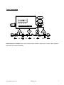
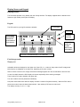
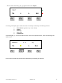
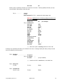
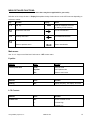
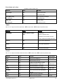
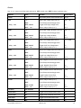
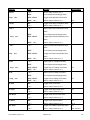
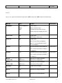
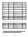
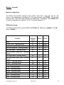
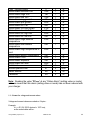
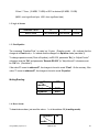
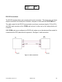
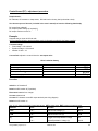
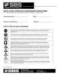
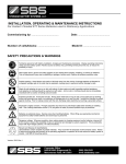
PSC-SERIES
BATTERY CHARGER
USER’S MANUAL
Storage Battery Systems, Inc.
MANUAL PSC
1
Table of Contents
INTRODUCTION.......................................................................................................................................................................................... 4
IMPORTANT SAFETY INSTRUCTIONS ................................................................................................................................................ 4
INSTALLATION........................................................................................................................................................................................... 5
PLACEMENT :...............................................................................................................................................................................................5
VENTILATION AND COOLING:..................................................................................................................................................................5
ELECTRICAL CONNECTION AND WIRING...............................................................................................................................................5
POWER UP .................................................................................................................................................................................................... 6
SYSTEM POWER OFF PROCEDURE...................................................................................................................................................... 6
THEORY OF OPERATION......................................................................................................................................................................... 7
DISPLAY SCREEN AND KEYPAD........................................................................................................................................................... 8
DISPLAY SCREEN........................................................................................................................................................................................8
Keypad:.................................................................................................................................................................................................. 8
Fixed charger mode:............................................................................................................................................................................ 8
Display unit..........................................................................................................................................................................................8
A CCESSING MENU VIA KEYPAD; OVERVIEW:.........................................................................................................................................9
M ENU STRUCTURE QUICK OVERVIEW:.................................................................................................................................................11
MENU DETAILED FUNCTIONS:.............................................................................................................................................................13
M AIN MENU: .............................................................................................................................................................................................13
Equalize:..............................................................................................................................................................................................13
LCD Contrast:.....................................................................................................................................................................................13
Reset alarms and relays:..................................................................................................................................................................14
Adjust:...................................................................................................................................................................................................14
Control:...............................................................................................................................................................................................14
Alarms:...............................................................................................................................................................................................15
Level 2: ...............................................................................................................................................................................................17
Readings:.............................................................................................................................................................................................18
MODBUS: (OPTIONAL)..........................................................................................................................................................................19
M ATERIAL CONFIGURATION : ...............................................................................................................................................................19
RAM MEMORY MAP :...............................................................................................................................................................................19
1.1 - Format for voltage and current values :...............................................................................................................................20
1.2- logic of alarms:...........................................................................................................................................................................21
1.3- Float/Equalize :..........................................................................................................................................................................21
1.4- Reset Alarm : ...............................................................................................................................................................................21
RS-232 CONNECTIONS: ............................................................................................................................................................................22
TROUBLE SHOOTING.............................................................................................................................................................................23
REGULAR PREVENTIVE MAINTENANCE...........................................................................................................................................24
CONTROL BOARD (PC) - ADJUSTMENT PROCEDURE................................................................................................................25
EXAMPLE:..................................................................................................................................................................................................25
Procedure ............................................................................................................................................................................................25
ALARMS ADJUSTMENT PROCEDURE..............................................................................................................................................26
EXAMPLE:..................................................................................................................................................................................................26
Storage Battery Systems, Inc.
MANUAL PSC
2
Procedure ............................................................................................................................................................................................26
W ARRANTY...............................................................................................................................................................................................28
ANNEXES:....................................................................................................................................................................................................29
ELECTRIC DIAGRAM.................................................................................................................................................................................29
PART LIST ..................................................................................................................................................................................................29
M ECHANICAL DRAWINGS .......................................................................................................................................................................29
TEST REPORT ............................................................................................................................................................................................29
Storage Battery Systems, Inc.
MANUAL PSC
3
Introduction
Thank you for having chosen Storage Battery Systems, Inc. The PSC-series battery charger is designed to provide
quality DC power for many years.
This user's manual contains important technical instructions to be followed by qualified personnel
responsible for the installation, start-up and maintenance of this unit. We recommend that this manual be
read attentively to insure safe and reliable operation of this equipment.
Should you require any assistance, please call our service department at:
Storage Battery Systems, Inc.
N56 W16665 Ridgewood Dr.
Menomonee Falls, WI 53051
Tel: (262) 703-5800
Fax: (262) 703-3073
E-mail: [email protected]
Web site : www.sbsbattery.com
IMPORTANT SAFETY INSTRUCTIONS
Keep these instructions in a safe place: this manual contains important safety and operating instructions
•
AC and DC currents are present in this system even with indicators and breakers are on “OFF”
position.
•
Before performing any maintenance on this system make sure that the battery and the AC power are
disconnected.
•
Experienced and qualified personnel only must perform maintenance.
•
Electrostatic sensitive components are used in this equipment. Proper ESD (electrostatic discharge)
•
procedures must be followed to prevent any severe damage to electronic components.
Working in the vicinity of a lead acid battery is dangerous: batteries generate explosive gases during
normal operation. Therefore never smoke or allow an open spark or flame in the vicinity of the battery
or engine.
•
To reduce risk of battery explosion, follow these instructions and those on the battery.
•
Never charge a frozen battery.
Storage Battery Systems, Inc.
MANUAL PSC
4
Installation
Placement:
FOR INSTALLATION, PLEASE REFER TO NATIONAL AND LOCAL ELECTRICAL CODES.
The system is a very heavy equipment. To prevent personal injury or equipment damage, use lifts and
extreme care when handling.
Ventilation and cooling:
The rectifier/charger is rated to better perform within 18°F (–10°C) and 122°F (+50°C) temperature range.
To calculate the required air displacement (exchange) volume, please use the following equation:
V = BTU x e
(0.125 x H x Tk/To)
/ (Tr -Tk)
V = air flow: [cubic meter/hour]
BTU: Total dissipated heat
Tr: Maximum allowed room temperature [°K] {i.e. 50°C = 323°K]
Tk= Temperature of input cooling air
To= 273 °K
H = Altitude [km]
Avoid placing the system in direct sunlight
N.B.
to insure adequate ventilation and safe access make sure that the following clearances are respected:
•
3 in. (10 cm) on the sides and top
•
3 feet (1 meter) in front of the unit.
Should seismic conditions require a more secure installation the unit may be bolted to the floor. Four (4) holes
are provided for this purpose.
Electrical Connection and wiring
Before Connecting the PSC battery charger make sure that:
•
The battery is disconnected (if applicable)
•
The circuit breakers are OFF
•
The relays, fuses and circuit boards are installed
•
The unit is wired in accordance with the instructions (refer to the wiring connections and electrical diagram)
Storage Battery Systems, Inc.
MANUAL PSC
5
Wire size is very important, The nameplate provides the essential information regarding the input and output
voltages and currents.
Refer to your Local or National Electrical Code for WIRE GAUGE and GROUNDING instructions.
Wire ampere capacity must be sized to the maximal correspondent current.
Correct voltage and polarity are of critical importance. Check all connections for tightness and polarity.
Connect battery (if applicable) to the output terminals observing its polarity.
Power up
After all wires installation is completed and has been double checked, the unit may be powered up as follow:
•
Before to connect the load to the charger, compare the critical characteristics of the load with the critical
characteristics of the charger (i.e. measure ondulation, line-neutral tension, positive-neutral tension).
•
Keep a log of manipulations (i.e. VFLOAT and VEQUALIZE values entered, alarm messages, alarm and SCR
blinking leds).
•
All input and output breakers must be on ”OFF” position
•
Apply power to the equipment from the source panel
•
Turn on AC breaker (”ON” position)
•
Turn on DC breaker (if supplied) (”ON” position)
•
Green LED must turn ON
•
Wait 5 seconds till the indication Screen (LCD) indicates the system output voltage and status
•
The system soft starts by rising the output current and the voltage
If readings or calibration of the unit is necessary, refer to the field programming section for more information.
System power Off procedure
•
Open the AC breaker (OFF position)
•
Open the DC breaker (if supplied) (OFF position)
•
Open the source panel’s AC breaker (OFF position)
•
If work inside the unit has to be performed, wait 5 minutes to discharge the filter capacitors or use bleeding
resistors of the correct rating to discharge the capacitors.
Now the system can be considered de-energized.
Storage Battery Systems, Inc.
MANUAL PSC
6
Theory of operation
DISPLAY
MODE FLt
Eq
Ok
Exit
F1
F2
F3
SEQUENTIAL
ACCESS MSG
F4
ALARMS
T1 : the ACMANUAL
supply is transformed and isolated.
INPUT
CONTROL BOARD PC 20/21///////
SCR: the transformer secondary voltage is rectified by a full-wave, half-controlled bridge.
I/P
V REG
MONITORING
A LIMIT
V
O/P
A
L1, C1 (optional) : the rectified DC voltage
is smoothed by lC filter section.
T1
L1
AC
MONITORING
F1
IN
Shunt : current and
voltage reading sent to the SCR
control
board
V
V
t
t
DC
OUT
V
Shunt
+
t
F1 : a fuse protects the SCR's and diodes.
Control Board: the PC20/21 series control board provides automatic charge control, precise voltage regulation,
alarm status annunciation and display.
Storage Battery Systems, Inc.
MANUAL PSC
7
Display Screen and Keypad
Display Screen
The PSC-series provides a very flexible and user friendly interface. The display supplied with the standard unit’s
features a high visibility, back light LCD display.
Keypad:
TO CHOOSE
The PSC used four (4) long life membrane switches.
AC ON
FLOAT MODE
OR ANOTHER
MESSAGES
DESCRIBED IN
THIS MANUAL
MODE FLt
Eq
Ok
Exit
F1
F2
F3
F4
ALARMS
ACTIVES
EQUALIZE
MODE OR
OTHER
MESSAGES
DESCRIBED
EACH KEY CORRESPONDS TO A FUNCTION
ABOVE
Fixed charger mode:
Display unit
Adjustable values are displayed on the higher row of the LCD, i.e. number of relays, alarm On/Off, voltage level.
Keys function are displayed on the lower row, depending of the menu context.
When an alarm is active on the charger exact failure message appears and the red led blinks to warn the user.
In case of multiple alarms the PSC display unit shows sequentially all the warning messages.
There is also an AC sector detection led (green led).
The user is able to save his parameters individually.
LCD power save feature shut down the display unit after 5 minutes of keyboard inactivity. When the PSC enter in
power save mode it saves the latest values entered. Upon wake-up PSC return to main menu.
The display accuracy is ± 2%, ± 1 digit
Storage Battery Systems, Inc.
MANUAL PSC
8
Accessing menu via keypad; overview:
On power-up the following readings appears on the screen (example):
131.4V
0.0A
Equalize
F1
F2
F3
F4
From that point, if you press any key of F1 to F4, only once, you reach the menu screen:
ß à
MODE Flt
Ok
F1
Eq
à
ß
F2
F3
Exit
F4
F1 (Ok), gives you access to Float / Equalize menu. Press F4(Exit) to step back to the menu.
From the menu, you may reach the different functions by pressing F2(à):
ß à
MODE Flt
Ok
F1
Storage Battery Systems, Inc.
Eq
à
ß
F2
F3
MANUAL PSC
Exit
F4
9
…after one touch of the F2 (à) key, you get the first function “Adjust”:
Adjust?
Ok
F1
à
ß
F2
F3
Exit
F4
Continuing pressing F2 (à) will make the screen successively scroll through the following functions:
à
à
à
à
à
Reset Alarm ? (present only in case of alarm)
Adjust?
Reading?
Relay test?
Contrast LCD
And pressing F3 (ß), 4 times, will make the screen scroll in the opposite direction, back to the following initial
menu screen:
ß à
MODE Flt
Ok
F1
Eq
à
ß
F2
F3
Exit
F4
Each function has itself many sub-functions represented by the following tree structure.
Storage Battery Systems, Inc.
MANUAL PSC
10
Menu structure quick overview:
(some of the below menu items may be not applicable for your order)
From the previous menu screen, press F2
F2 (à) Reset Alarm? (visible only in case of alarm)
F2 (à) Adjust?
F1 (Ok)
Enter Password F2 F1 F3 (…password for fixed charger only)
(Warning: Modifications to the following settings affect output voltage and
output current of the charger and should be done only by qualified
technician)
…
Control?
F1 (Ok)
Float
F2 (à) I Lim
Eq
TEQ
LVEQ
TALimEq
AC Eq
T Float
124.9
23.3A
131.5 On
08 H
106.1V On
05mn On
On
30 D
(for example)
*
*
*
*
*
( * ) : available only if Eq is “On”
F2(à) ………………
Alarm?
F1 (Ok)
Talarm
F2 (à) HVAL
…
HVSH
L VAL
L Vdis
GNDFGNDF+
AC Fail
LCD latch
Com Al latch
Ind Al latch
Audio Alarm
Mesg latch
Rct. fail
Htemp
H Ext T
L Ext T
ACHV
ACLV
Fuse
Hi ripple
I lim Alarm
Eq Alarm
Storage Battery Systems, Inc.
10 S (for example)
138.1V On
90.2V Off
100.0V On
61.5V On
5.0mA Off
5.0mA Off
On
Off
Off
Off
Off
Off
On
Off
100C Off
00C
Off
160.0V Off
0.0V
Off
Off
Off
Off
Off
MANUAL PSC
11
Bat. disch
Off
Pressing F3(ß) repetitively will make you scroll back in the menu. Pressing F4(Exit) will make you step
one level back in the hierarchy of the tree menu.
F2(à) ……………
Level2?
F1 (Ok)
Enter Password F2 F1 F3 (…password for fixed charger only)
(Warning: Modifications to the following settings should be done
by qualified technician)
Display Off
F2(à) Default value
…
Nom Volt
Nom AMP
DCV cal
DCA cal
AC display
ACV cal
ACA cal
VMIN
VMAX
IMAX
Remote V sens Off
Load sharing
Tcomp
LCD Pwr save
Remote EQ
AH display
Batt capa
Off
(for example)
150V
25 A
132.0V
0.0A
Off
*
78.4V
539.5A
0.0V
160.0V
*02.2A
Off
Off
Off
Off
Off
*
100AH
( * ) : affect menu option in Reading submenu if set to “ON”
Pressing F3(ß) repetitively will make you scroll back in the menu. Pressing F4(Exit) will make you step one level
back in the hierarchy of the tree menu.
F2(à) Reading?
F1 (Ok) : ……………………….. Frequence
F2(à) AC display
…
AH meter
*
*
(not yet available)
( * ) : must be set “ON” in Level2 menu, to be visible here
F2(à) Relay test?
F1 (Ok) :
F1(Yes)
F4(No)
F2(à) Contrast LCD
Press F1 (Ok) :
F1(Set)
F4(No)
Storage Battery Systems, Inc.
MANUAL PSC
12
MENU DETAILED FUNCTIONS:
(some of the below menu items may be not applicable for your order)
Definition of the 4 keys functions. Display field explains the key function shown on the LCD lower row depending on
sub-menu context.
Key
ACTION
F1
“Ok” key
Display
OK
NOTE
Enter the displayed sub-menu
(or Set key for sub-function)
F2
Scroll Down sub-menu
Go UP next selection
F3
Scroll Up sub-menu
Go DOWN last selection
F4
Exit
Return to previous menu
Return last selection
Main menu:
Use à or ß keys to scroll the level 0 sub-menus. SET to enter menu.
Equalize:
DISPLAY
Press
ACTION
Float Equalize Exit
Float
Set float mode
Equalize
Set Equalize mode
Exit
Return to main menu
DISPLAY
Press
ACTION
Reading
SET
Display frequency, AC display, AH meter
DISPLAY
Press
ACTION
Contrast LCD
SET
Access contrast control
+
Contrast High
–
Contrast Low
LCD Contrast:
Storage Battery Systems, Inc.
MANUAL PSC
13
Reset alarms and relays:
(available in case of alarm only)
DISPLAY
Press
ACTION
Reset relays
Yes
Reset all the relays
No
Go to Reset alarm
Reset Alarm msg
Yes
Clear all alarms messages
(not displayed)
No
Go to Relay test
Relay Test
Yes
Test all relays
(not displayed)
No
Go back one level
Adjust:
Use à or ß keys to scroll the sub-menus. SET to enter menu. EXIT to return to previous menu.
DISPLAY
Press
ACTION
PASSWORD
F2-F1-F3 (Push in order)
Enter Level 1
EXIT
Return to previous menu
Password must be valid to access
Control, Alarms and reading sub-menu
Control?
SET
Go to Control adjustments
Alarms?
SET
Go to alarm adjustments
Level 2?
SET
Go to level 2 sub-menu
Control:
Use à or ß keys to scroll the Control sub-menus. SET to enter menu. EXIT to return to previous menu.
DISPLAY
Press
ACTION
Default Value
Float
+ or -
Adjust Float Voltage (V)
Vnom X 1.09
I LIM
+ or -
Adjust Current Limit (A)
Eq
SET
Toggle On/Off Equalization Voltage
On
+ or -
Adjust Equalization Voltage (V)
Vnom X 1.12
T eq
+ or -
Adjust Equalization Time (Hour)
L VEQ
+ or -
Adjust Low Equalization Voltage (V)
Vfloat X 0.85
TA LIM E
+ or -
Adjust Time/Current limit Equalization
5 min
(Minute)
ACEq
SET
Toggle On/Off AC Equalization
On
Tfloat
+ or -
Adjust Float Timing (Days)
28 Days
Storage Battery Systems, Inc.
MANUAL PSC
14
Alarms:
Use à or ß keys to scroll the Alarm sub-menus. SET to enter menu. EXIT to return to previous menu.
DISPLAY
Press
ACTION
Default Value
Talarm
+ or –
Adjust delay before alarm activates (sec)
10 sec
HVAL
+ or –
Adjust High Voltage alarm level (V)
Veq x 1.05
NEXT
Go to Relays selection/toggle menu
NEXT, On/Off
Toggle On/Off High Voltage alarm
On
NEXT, + or –
Select relays number (1 to 7)
No. 2
+ or –
Adjust High Voltage Shutdown level (V)
Veq x 1.1
NEXT
Go to Relays selection/toggle menu
NEXT, On/Off
Toggle High voltage shutdown
Off
NEXT, + or –
Select relays number (1 to 7)
No. 8
+ or –
Adjust Low Voltage alarm level (V)
0.8 x Vfloat
NEXT
Go to Relays selection/toggle menu
NEXT, On/Off
Toggle On/Off Low Voltage alarm
On
NEXT, + or –
Select relays number (1 to 7)
No.3
+ or –
Adjust Low Voltage Disconnect level (V)
NEXT
Go to Relays selection/toggle menu
NEXT, On/Off
Toggle Low voltage Disconnect
NEXT, + or –
Select relays number (1 to 7)
No. 4
+ or –
Adjust Negative Ground Fault level (mA)
5 mA
NEXT
Go to Relays selection/toggle menu
NEXT, On/Off
Toggle Negative Ground Fault
On
NEXT, + or –
Select relays number (1 to 7)
No. 4
+ or –
Adjust Positive Ground Fault level (mA)
5 mA
NEXT
Go to Relays selection/toggle menu
NEXT, On/Off
Toggle Positive Ground Fault
On
NEXT, + or –
Select relays number (1 to 7)
No. 4
+ or –
Select relays number (1 to 7)
NEXT
Go to Relays selection/toggle menu
NEXT, On/Off
Toggle On/Off AC Failure Alarm
On
NEXT, + or –
Select relays number (1 to 7)
No.5
relay
xxx
HVSH
relay
xxx
LVAL
relay
xxx
LVDis
relay
xxx
GNDF–
relay
xxx
GNDF+
relay
xxx
AC Fail
LCD latch
Not available
Com Al latch
SET
Toggle On/Off Common Alarm Latch
Off
Ind alm latch
SET
Toggle On/Off Individual Alarm Latch
On
Audio latch
SET
Toggle On/Off Audio Alarm Latch
Off
Mesg latch
SET
Toggle On/Off Alarm Display Latch
On
Storage Battery Systems, Inc.
MANUAL PSC
15
DISPLAY
Press
ACTION
Default Value
Rct fail
+ or –
Select relays number (1 to 7)
On
NEXT
Go to Relays selection/toggle menu
NEXT, On/Off
Toggle On/Off Rectifier Failure alarm
NEXT, + or –
Select relays number (1 to 7)
No.1
SET
Toggle On/Off High Temperature alarm
On
+ or –
Select relays number (1 to 7)
+ or –
Adjust High External temperature level
relay
xxx
H temp
H ext T
Alarm
relay
xxx
NEXT
Go to Relays selection/toggle menu
NEXT, On/Off
Toggle High External temperature level
Alarm
L ext T
NEXT, + or –
Select relays number (1 to 7)
+ or –
Adjust Low External temperature level
Alarm
relay
xxx
NEXT
Go to Relays selection/toggle menu
NEXT, On/Off
Toggle Low External temperature level
Alarm
ACVH
relay
xxx
ACVL
relay
xxx
DC Fuse
Hi ripple
Ilim Alarm
Eq Alarm
Bat, disch
Storage Battery Systems, Inc.
NEXT, + or –
Select relays number (1 to 7)
+ or –
Adjust High AC Voltage level alarm
NEXT
Go to Relays selection/toggle menu
NEXT, On/Off
Toggle High AC Voltage Level Alarm
NEXT, + or –
Select relays number (1 to 7)
+ or –
Adjust Low AC Voltage level alarm
NEXT
Go to Relays selection/toggle menu
NEXT, On/Off
Toggle Low AC Voltage Level Alarm
NEXT, + or –
Select relays number (1 to 7)
SET
Toggle On/Off Fuse alarm
+ or –
Select relays number (1 to 7)
SET
Toggle On/Off High Ripple alarm
+ or –
Select relays number (1 to 7)
SET
Toggle On/Off Current Limit alarm
+ or –
Select relays number (1 to 7)
SET
Toggle On/Off Equalize alarm
Off
+ or –
Select relays number (1 to 7)
No. 4
SET
Toggle On/Off Battery Discharge alarm
Off
+ or –
Select relays number (1 to 7)
Batt. Current >
MANUAL PSC
Off
Off
Off
16
O/P current
Level 2:
Use à or ß keys to scroll the level 2 sub-menus. SET to enter menu. EXIT to return to previous menu
DISPLAY
Press
ACTION
PASSWORD
F2-F1-F3 (follow in
Enters Level 2
order)
Return to previous menu
EXIT
Password must be valid to access
Default Value
Control, Alarms and reading sub-menu
Default Value
SET
Toggle On/Off
Select factory value On/Off
Display Off
SET
Toggle On/Off
When Off, all values are displayed
When On, only values that are set to
“On” are displayed
NomVolt
+ or -
Adjust the Nominal Voltage displayed
Factory preset
Once values is set Nominal Voltage is
not displayed
NomAmp
+ or -
Adjust the Nominal Ampere displayed
Factory preset
Once values is set Nominal Ampere is
not displayed
DCV cal
+ or -
Adjust the DC Voltage calibration
NEXT, + or -
Adjust the DC Voltage offset
+ or -
Adjust the DC Current calibration
NEXT, + or -
Adjust the DC Current offset
AC display
SET
Toggle On/Off AC display
ACV cal
+ or -
Adjust the AC Voltage calibration
offset XXX
DCA cal
offset XXX
ACA cal
Storage Battery Systems, Inc.
Off
Adjust the AC Current calibration
MANUAL PSC
17
VMIN
+ or -
Adjust the Minimum Output Voltage
Default value is 0
VMAX
+ or -
Adjust the Maximum Output Voltage
IMAX
+ or -
Adjust the Maximum Output Current
Remote V sens
SET
Toggle On/Off the Remote Voltage
Off
Sensing
Load sharing
SET
Toggle On/Off the Load Sharing
Off
Negative slope
regulation
Tcomp
SET
Toggle On/Off Temperature
Off
Compensation
LCD pwr save
SET
Toggle On/Off LCD power save
Off
After 5 min of inaction on LCD goes on
power save
Remote Eq
SET
Toggle On/Off Remote Equalization
Off
AH display
SET
Toggle On/Off Ampere/Hour display
Off
Bat cap
+ or -
Adjust the Ampere/Hour capacity of
Battery
Readings:
Use à or ß keys to scroll the Reading sub-menus. SET to enter menu. EXIT to return to previous menu.
DISPLAY
Press
ACTION
Default Value
Actual frequency
Active
L
Display AC voltage
Off
N
Display AC current
Off
Display Ampere/ Hour in percent
Off
Display Ampere/ hour
Off
Frequency
AC display
AH meter
** : If FIXED CHARGER mode is on “OFF” position then no alarms, float, equalize modes are accessible.
(i.e. software exits set up mode after having chosen variable current or/and voltage)
Storage Battery Systems, Inc.
MANUAL PSC
18
Modbus: (optional)
Material configuration :
The RS-232 communication operate in slave modbus, with 8 bits, 1 start and 1 stop bit. The
speed of the transmission is configured on the communication card (PCOM). The available
speed are 300, 1200, 4800, 9600 (default) and 19200 bauds. The address of the PCOM card is
on board configurable from address 1 to 255. The default address is “1“ .
RAM memory map:
The following map show the structure RAM of the PCOM card. (R) mean « readable » and (W)
mean « writable ».
Variable
Vout
Vfloat / Vref (setting value)
Vequalize (setting value)
Volt low equalize (setting value)
Volt low alarm (setting value)
Volt low alarm disconnect (setting
value)
Volt high alarm (setting value)
Volt high alarm shut down (setting
value)
GNDF+ (setting value)
GNDF- (setting value)
I out (setting value)
I Lim (setting value)
V ph1 (setting value)
V ph2 (setting value)
V ph3 (setting value)
I ph1 (setting value)
I ph2 (setting value)
Storage Battery Systems, Inc.
Address
(dec)
00
01
02
03
04
05
Bytes
Status
2
2
2
2
2
2
R
W/R
W/R
R
R
R
06
07
2
2
R
R
08
09
10
11
12
13
14
15
16
2
2
2
2
2
2
2
2
2
R
R
R
W/R
R
R
R
R
R
MANUAL PSC
19
I ph3 (setting value)
Status Alarm Rectifier Fail
Status Alarm High Volt
Status Alarm low Volt
Status Alarm neg ground
Status Alarm pos ground
Status Alarm AC Fail
Status Alarm HV Shut Down
Status Alarm Low Volt Disc
Status Alarm AC high volt
Status Alarm AC low volt
Status Alarm High external
temperature
Status Alarm low external
temperature
Status Alarm High temperature of
card
Status Alarm Battery Discharging
Status Alarm I Lim
Status Alarm Equalize
Status Alarm cut fuse
Not Used
Mode Equalize/Float
Reset Alarms
Password
17
18H
18L
19H
19L
20H
20L
21H
21L
22H
22L
23H
2
1
1
1
1
1
1
1
1
1
1
1
R
R
R
R
R
R
R
R
R
R
R
R
23L
1
R
24H
1
R
24L
25H
25L
26H
26L
27
28
29
1
1
1
1
X
2
2
2
R
R
R
R
X
W/R
W
W
Table 1
Note: Reading the value “FF(HEX)” at any “Status Alarm” (setting value or mode)
address means that this alarm (setting value or mode) has not been ordered with
your charger.
1.1 - Format for voltage and current values :
Voltage and current values are coded on 2 bytes :
Example:
Vout = 651.3V (6513 decimal = 1971 hex),
so the coded value will be :
Storage Battery Systems, Inc.
MANUAL PSC
20
19 hex / 71 hex; (19 MSB, 71 LSB) or 6513 in decimal (65 MSB, 13 LSB)
(MSB : most significant byte, LSB : less significant byte)
1.2- logic of alarms:
Address value
alarm state
FF
Not available
0
Not active
1
Active
Table 2
1.3- Float/Equalize :
The command “Equalize/Float“ is coded on 2 bytes. (Reading mode) : « 0 » indicate that the
charger is in Float mode, « 1 » indicate that the charger is in Equalize mode (see table 3).
To change operation mode (Float or Equalize), via RS-232, parameter “Eq” (in “Adjust\Control”
submenu) must be “ON” and parameter “Remote RS-232” (in “Adjust\Level2” submenu) must
be “ON” too. (See table 3)
If the value “0” is sent to address 27, the charger is forced to mode “Float”. On the contrary, if the
value “1” is sent to address 27, the charger is forced to mode “Equalize”.
Writing/Reading :
address
mode
float
equalize
27
0000
0001
Table 3
1.4- Reset Alarm :
To deactivate an alarm, just send the value « 1 » at the address 28 (in writing mode).
address
28
mode
Storage Battery Systems, Inc.
MANUAL PSC
21
alarm
reset
0001
Table 4
RS-232 Connections:
The RS-232 standard allows only a single point-to-point connection. This means only one device
may be connected to the serial port of a modem, computer or in this case the SBS PCOM card.
The cable needed for the RS-232 communication must have a maximum length of 15.2m (50 ft.),
with DB9 male connector at the PCOM card end and to other end on the mating device port
connector.
SBS PCOM card comes configured as RS-232 null modem so no other device will be needed for
connection with a DTE (data terminal equipment). See figure 1 cable connection.
Figure 1: cable connections
Storage Battery Systems, Inc.
MANUAL PSC
22
Trouble shooting
Field programming
Should trouble occur with your PSC rectifier please read the following:
Warning: qualified personnel should service this unit only. The battery and AC supply should be disconnected
before replacing any component.
Fault
No output
abnormal noise
Recommendation
-
verify that the AC breaker is closed ("ON")
-
verify that the AC supply is of correct voltage and frequency
-
verify the DC output fuse
-
verify the output and input connections
-
replace control board PC20/21
-
replace thyristor modules
- verify thyristors
- replace control board PC20/21
If trouble persists please contact our service department at:
Storage Battery Systems, Inc.
N56 W16665 Ridgewood Dr.
Menomonee Falls, WI 53051
Tel: (262) 703-5800
Fax: (262) 703-3073
E-mail: sbs@ sbsbattery.com
Web site: www.sbsbattery.com
Storage Battery Systems, Inc.
MANUAL PSC
23
Regular preventive maintenance
Regular maintenance is required to insure reliable operation of your system.
Action
frequency
B
measure and record the voltage
across each battery cell and across
the entire battery.
monthly
B
verify and record the electrolyte level
vented battery in each battery cell.
If necessary top off with distilled water
monthly
B
verify and record the specific gravity
of each battery cell
monthly
C
verify the operation of all indicators
monthly
B, C
using vacuum cleaner equipped with a
small brush removes accumulated dust
especially around ventilation openings
yearly
B, C
visually verify the condition of all
components
yearly
B, C
verify all connections. If necessary
recommended uses of torque re-torque
to manufacturers specifications wrench
yearly
B
clean and re-grease all battery
connections
yearly
B
wash battery using distilled water only
yearly
B = battery
C = charger
For systems supplied with lead acid batteries, a partial discharge of the battery is recommended on an annual
basis, to verify battery and charger performance.
For systems supplied with nickel-cadmium batteries we recommend a complete discharge and decommissioning
charge on a bi-annual basis. SBS provides both these services.
Storage Battery Systems, Inc.
MANUAL PSC
24
Control board (PC) - adjustment procedure
Required tools:
DC voltmeter, DC ammeter or clamp-meter, DC load bank or dummy load (to simulate a load).
Use the test report of the unit ( included in the user's manual) to have the following data handy:
DC output float voltage Vf
DC output equalize voltage (if required) Ve
DC output maximum current im
Example :
Suppose that you have 18 Ni-Cad cells:
(for your specific Ni-Cad or lead acid please use the information provided by the battery supplier)
Constant voltage:
• Float voltage =1.42 volt/cell
• Equalize voltage =1.55 volt/cell
• Number of cells = 18
Current limit: adjust the current limit to the test report value
Nickel cadmium battery
Float voltage Vf
A
B
Number of cells x 1,42*v/cell
Equalize voltage Ve
Number of cells x 1,55**v/cell
Auto equalize level Vae
Vf x 0,85
Maximum charging current Imax
Imax
C
25,6 v
27.9v
21.76 v
5 Amp.
Procedure
switch the AC breaker off.
Switch the DC breaker off (if provided).
Disconnect batteries from charger.
Connect resistive load
Connect DC voltmeter across DC output terminal (see wiring diagram)
Switch the AC breaker on.
Use à or ß keys to scroll the Control sub-menus. SET to enter menu. EXIT to return to previous menu
DISPLAY
Press
ACTION
Value
Float
+ or -
Adjust Float Voltage (V)
25,6 V
I LIM
+ or -
Adjust Current Limit (A)
5,0 A
Eq
SET
Toggle On/Off Equalization Voltage
On
+ or -
Adjust Equalization Voltage (V)
27,9 V
Storage Battery Systems, Inc.
MANUAL PSC
25
T eq
+ or -
Adjust Equalization Time (Hour)
L VEQ
+ or -
Adjust Low Equalization Voltage (V)
21,76 V
TI LIM E
+ or -
Adjust Time/Current limit Equalization
5 min
(Minute)
AC Eq
SET
Toggle On/Off AC Equalization
On
Tfloat
+ or -
Adjust Float Timing (Days)
28 Days
Alarms adjustment procedure
Required tools:
DC voltmeter, DC ammeter or clamp-meter, DC load bank or dummy load (to simulate a load).
Use the test report of the unit ( included in the user's manual) to have the following data handy :
DC output float voltage Vf
DC output equalize voltage (if required) Ve
DC output maximum current Im
Example :
Suppose that you have 18 Ni-Cad cells:
(for your specific Ni-Cad or lead acid please use the information provided by the battery supplier)
Constant voltage:
• Float voltage =1.42 Volt/cell
• Equalize voltage =1.55 volt/cell
• Number of cells = 18
Nickel cadmium battery
Float voltage Vf
A
B
Number of cells x 1,42* v/cell
Equalize voltage Ve
Number of cells x 1,55** v/cell
High volts alarm Vh
Ve x 1,03
Low volts alarm VL
Vf x 0,8
C
25.6 v
27.9v
28.7 v
20.4 v
Notes: *, ** float and equalize voltage provided by the battery manufacturer
Procedure
switch the AC breaker off.
Switch the DC breaker off (if provided).
Disconnect batteries from charger.
Connect resistive load
Connect DC voltmeter across DC output terminal (see wiring diagram)
Switch the AC breaker on.
Storage Battery Systems, Inc.
MANUAL PSC
26
Use à or ß keys to scroll the level 2 sub-menus. SET to enter menu. EXIT to return to previous menu
DISPLAY
Press
ACTION
Default Value
Talarm
+ or –
Adjust alarm Timing (sec)
10 sec
HVAL
+ or –
Adjust High Voltage alarm level (V)
28,7 V
NEXT
Go to Relays selection/toggle menu
NEXT, On/Off
Toggle On/Off High Voltage alarm
On
NEXT, + or –
Select relays number (1 to 7)
No. 2
+ or –
Adjust Low Voltage alarm level (V)
20,4 V
NEXT
Go to Relays selection/toggle menu
NEXT, On/Off
Toggle On/Off Low Voltage alarm
On
NEXT, + or –
Select relays number (1 to 7)
No.3
+ or –
Adjust Negative Ground Fault level (mA)
5 mA
NEXT
Go to Relays selection/toggle menu
NEXT, On/Off
Toggle Negative Ground Fault
On
NEXT, + or –
Select relays number (1 to 7)
No. 4
+ or –
Adjust Positive Ground Fault level (mA)
5 mA
NEXT
Go to Relays selection/toggle menu
NEXT, On/Off
Toggle Positive Ground Fault
On
NEXT, + or –
Select relays number (1 to 7)
No. 4
+ or –
Select relays number (1 to 7)
NEXT
Go to Relays selection/toggle menu
NEXT, On/Off
Toggle On/Off AC Failure Alarm
On
NEXT, + or –
Select relays number (1 to 7)
No.5
+ or –
Select relays number (1 to 7)
NEXT
Go to Relays selection/toggle menu
NEXT, On/Off
Toggle On/Off AC Failure Alarm
On
NEXT, + or –
Select relays number (1 to 7)
No.1
relay
xxx
LVAL
relay
xxx
GNDF–
relay
xxx
GNDF+
relay
xxx
AC Fail
Rectifier Fail
Storage Battery Systems, Inc.
MANUAL PSC
27
Warranty
Electrical / Electronic Products Warranty
SBS/Primax warrants to the original user that its rectifying equipment, load banks, DC-DC converters,
batteries, chargers and UPS systems are free from defects in factory workmanship and materials, such
warranty being conditional upon the product having been installed, commissioned, operated and
maintained by qualified personnel and according to manufacturer instructions.
SBS's liability is limited to repairing or replacing without charge at its factory any product or component
which at user's expense has been returned to SBS or authorized service center within 1 year from date
of commissioning whichever occurs first. SBS's repair or replacement of any defective product shall
constitute fulfillment of his obligations.
This warranty applies to manufacturer products which are shown by the purchaser to have been
originally defective and shall not apply to products which must be repaired or replaced due to normal
wear, misuse, negligence, wreckage, accident, any act of god or to products which have been repaired
or altered outside of seller's factory or one of its authorized service centers unless authorized solely by
SBS.
SBS shall not be liable for loss, damage, or expense, consequential or otherwise from the use of its
products or from any other cause.
This warranty supersedes and is given in place of all other warranties expressed or implied or
conditions whether statutory or otherwise as to quality and fitness for any purpose for which the
products are supplied. No person, agent or dealer is authorized to give any warranty on behalf of
manufacturer or to assume for seller any other liability in connection with any of its products unless
made in writing and signed by an officer of SBS.
Storage Battery Systems, Inc.
N56 W16665 Ridgewood Dr.
Menomonee Falls, WI 53051
Tel: (262) 703-5800
Fax: (262) 703-3073
E-mail: [email protected]
Web site : www.sbsbattery.com
Storage Battery Systems, Inc.
MANUAL PSC
28
ANNEXES:
Electric diagram
Part list
Mechanical Drawings
Test report
Storage Battery Systems, Inc.
MANUAL PSC
29