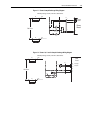
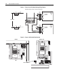
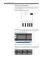
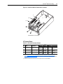
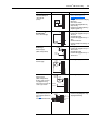
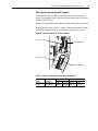
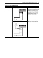
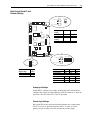
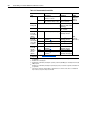
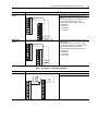
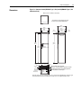
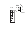
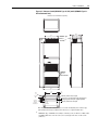
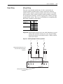
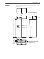
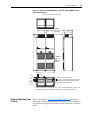
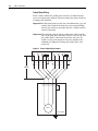
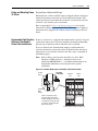
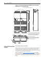
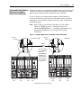
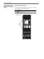
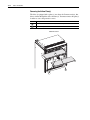
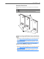
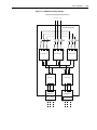
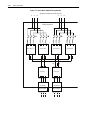
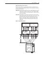
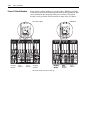
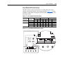
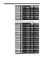
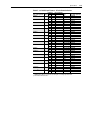
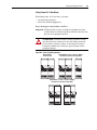
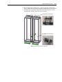
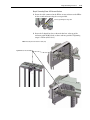
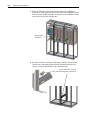
1
PowerFlex® 700H Adjustable Frequency AC Drive /
PowerFlex® 700S High Performance AC Drive
INSTALLATION MANUAL
Frames 9 - 14
Important User Information
Solid state equipment has operational characteristics differing from those of
electromechanical equipment. Safety Guidelines for the Application,
Installation and Maintenance of Solid State Controls (Publication SGI-1.1
available from your local Rockwell Automation sales office or online at http://
www.rockwellautomation.com/literature) describes some important differences
between solid state equipment and hard-wired electromechanical devices.
Because of this difference, and also because of the wide variety of uses for solid
state equipment, all persons responsible for applying this equipment must
satisfy themselves that each intended application of this equipment is
acceptable.
In no event will Rockwell Automation, Inc. be responsible or liable for indirect
or consequential damages resulting from the use or application of this
equipment.
The examples and diagrams in this manual are included solely for illustrative
purposes. Because of the many variables and requirements associated with any
particular installation, Rockwell Automation, Inc. cannot assume responsibility
or liability for actual use based on the examples and diagrams.
No patent liability is assumed by Rockwell Automation, Inc. with respect to use
of information, circuits, equipment, or software described in this manual.
Reproduction of the contents of this manual, in whole or in part, without
written permission of Rockwell Automation, Inc. is prohibited.
Throughout this manual, when necessary we use notes to make you aware of
safety considerations.
!
WARNING: Identifies information about practices or
circumstances that can cause an explosion in a hazardous
environment, which may lead to personal injury or death, property
damage, or economic loss.
Important: Identifies information that is critical for successful application and
understanding of the product.
!
ATTENTION: Identifies information about practices or
circumstances that can lead to personal injury or death, property
damage, or economic loss. Attentions help you identify a hazard,
avoid a hazard, and recognize the consequences.
Shock Hazard labels may be located on or inside the equipment
(e.g., drive or motor) to alert people that dangerous voltage may be
present.
Burn Hazard labels may be located on or inside the equipment
(e.g., drive or motor) to alert people that surfaces may be at
dangerous temperatures.
PowerFlex, DriveExplorer, DriveTools SP, DPI, and SCANport are either trademarks or registered trademarks of Rockwell Automation, Inc.
Klixon® is a registered trademark of Sensata Technologies, Inc.
Summary of Changes
Manual Updates
The information below summarizes the changes to the PowerFlex 700H and
700S Installation Instructions, publication PFLEX-IN006, since the March
2006 release.
Change
Updated the Normal Duty power ratings
Updated the Reference Materials List
Added information on installations using single-phase input power
Updated the Common Bus/Precharge information
Added a description for the use of output reactors on frame 14 drives
Updated the 700H I/O board options chart
Updated the “Auto/Manual Notes” section to include information on enabling manual
mode to allow starts and jogs from the HIM in 2-wire mode
Added a note to the analog inputs on the 700S Phase II control
Added terminal wiring illustration for external brake resistor and external brake IGBT
and resistor connections on frame 9 drives
Updated all Frame 10 dimension drawings to include cable routing information.
Added a dimension drawing for the frame 10 Motor Control Center (MCC), Enclosure
Codes “B” and “K”
Updated the instructions for frame 10 Ungrounded, High Resistive Ground or Grounded
B Phase Delta installations
Updated the Power Terminal Block designations for frame 10 (removed brake option
terminals)
Updated all Frame 11 dimension drawings to include cable routing information.
Added a dimension drawing for the frame 11 Motor Control Center (MCC), Enclosure
Codes “B” and “K”
Updated the instructions for frame 11 Ungrounded, High Resistive Ground or Grounded
B Phase Delta installations
Updated all Frame 12 dimension drawings to include cable routing information.
Added a dimension drawing for the frame 12 Motor Control Center (MCC), Enclosure
Codes “B” and “K”
Updated the instructions for frame 12 Ungrounded, High Resistive Ground or Grounded
B Phase Delta installations
Updated all Frame 13 dimension drawings to include cable routing information.
Updated the frame 13 dimensions for the NEMA/UL Type 12 - IP54 Enclosures
Updated the instructions for frame 13 Ungrounded, High Resistive Ground or Grounded
B Phase Delta installations
Added Chapter 11 - Frame 14 Installation
Updated the Agency Certification information for drives with 700H control
Separated the drive ratings information from the drive protection devices - now in
separate tables
Updated the drive rating, fusing and circuit breaker specifications
Added new Appendix B to consolidate the common lifting and mounting instructions
Added the Allen-Bradley 842HR rotary encoder to the list of compatible encoders
Updated wiring diagrams for the Hi-Resolution Encoder
Updated wiring diagrams for Resolvers
Updated wiring diagrams for the MDI board
Added Appendix E on ATEX Approved PowerFlex 700H Drives in Group II Category (2)
Applications with ATEX Approved Motors
Page
Preface-1
Preface-1
1-2
1-9
1-2
2-2
2-12
4-4
6-6
7-1 - 7-5
7-4
7-9
7-14
8-1 - 8-5
8-4
8-9
9-1 - 9-5
9-4
9-9
10-3 - 10-4
10-4
10-5
11-1
A-1
A-5,
A-13
A-13
B-1
C-1
C-2
D-3
E-3
F-1
ii
Summary of Changes
The information below summarizes the changes to the PowerFlex 700H and
700S Installation Instructions, publication PFLEX-IN006, since the
October, 2004 release.
Change
Updated the drive ratings for PowerFlex 700H and 700S
Updated the information on installing unbalanced, ungrounded or resistive grounded
distribution systems
Added information on DC input precharge control wiring
Updated the “Control Board Slot Designations” table for the new 20C-DG1 digital I/O
option board
Added drive catalog numbers for 700H control I/O board options
Updated the “Analog Input, PTC 0-10V Input” wiring example
Added Chapter 4, “Control Wiring for PowerFlex 700S Drives with Series II Control”
Updated information on frame 9 operating temperatures
Updated frame 9 installation instructions for unbalanced, ungrounded or resistive
grounded distribution systems
Updated frame 10 minimum mounting clearances
Updated frame 10 operating temperatures
Added dimensions drawing for frame 10 NEMA/UL Type 12 - IP54 Enclosure
Updated frame 10 “Moving Control Frame” to show slotted holes in Control Frame
Updated frame 10 “Removing Protective Covers” to omit screws that were not present.
Updated frame 10 installation instructions for unbalanced, ungrounded or resistive
grounded distribution systems
Updated frame 11 minimum mounting clearances
Updated frame 11 operating temperatures
Added dimensions drawing for frame 11 NEMA/UL Type 12 - IP54 Enclosure
Updated frame 11 installation instructions for unbalanced, ungrounded or resistive
grounded distribution systems
Added Chapter 9, “Frame 12 Installation”
Added Chapter 10, “Frame 13 Installation”
Updated the agency certifications
Updated the drive protection specifications
Updated the fusing and circuit breaker specifications
Added specifications and wiring diagram for using the Stahltronic linear encoder
Page
Preface-1
1-1
1-10
2-2
2-2
2-8
4-1
6-2
6-4
7-1
7-2
7-5
7-6
7-8
7-9
8-1
8-2
8-5
8-9
9-1
10-1
A-1
A-1
A-13, A-13
E-3
Table of Contents
Important User Information . . . . . . . . . . . . . . . . . . . . . . . . . . . . . . . . . . . . . . . . . . . . . . . 1-2
Summary of
Changes
Manual Updates . . . . . . . . . . . . . . . . . . . . . . . . . . . . . . . . . . . . . . . . . . . . . . . . . . . . . . . . . 1-i
Preface
Overview
Drive Description . . . . . . . . . . . . . . . . . . . . . . . . . . . . . . . . . . . . . . . . . . . . . . . . . . . . . . .
Enclosure Options . . . . . . . . . . . . . . . . . . . . . . . . . . . . . . . . . . . . . . . . . . . . . . . . . . . . . . .
Who Should Use this Manual? . . . . . . . . . . . . . . . . . . . . . . . . . . . . . . . . . . . . . . . . . . . . .
What Is Not in this Manual . . . . . . . . . . . . . . . . . . . . . . . . . . . . . . . . . . . . . . . . . . . . . . . .
Reference Materials . . . . . . . . . . . . . . . . . . . . . . . . . . . . . . . . . . . . . . . . . . . . . . . . . . . . .
Manual Conventions . . . . . . . . . . . . . . . . . . . . . . . . . . . . . . . . . . . . . . . . . . . . . . . . . . . . .
Drive Frame Sizes . . . . . . . . . . . . . . . . . . . . . . . . . . . . . . . . . . . . . . . . . . . . . . . . . . . . . . .
General Precautions . . . . . . . . . . . . . . . . . . . . . . . . . . . . . . . . . . . . . . . . . . . . . . . . . . . . .
Chapter 1
General Installation Information
AC Supply Source Considerations . . . . . . . . . . . . . . . . . . . . . . . . . . . . . . . . . . . . . . . . . .
General Grounding Requirements. . . . . . . . . . . . . . . . . . . . . . . . . . . . . . . . . . . . . . . . . . .
Fuses and Circuit Breakers . . . . . . . . . . . . . . . . . . . . . . . . . . . . . . . . . . . . . . . . . . . . . . . .
Power Wiring. . . . . . . . . . . . . . . . . . . . . . . . . . . . . . . . . . . . . . . . . . . . . . . . . . . . . . . . . . .
EMC Instructions . . . . . . . . . . . . . . . . . . . . . . . . . . . . . . . . . . . . . . . . . . . . . . . . . . . . . . .
Using Input/Output Contactors . . . . . . . . . . . . . . . . . . . . . . . . . . . . . . . . . . . . . . . . . . . . .
Common Bus/Precharge . . . . . . . . . . . . . . . . . . . . . . . . . . . . . . . . . . . . . . . . . . . . . . . . . .
Chapter 2
P-1
P-1
P-2
P-2
P-2
P-3
P-4
P-5
1-1
1-3
1-4
1-4
1-7
1-9
1-9
PowerFlex® 700H Control Wiring
Reference Control . . . . . . . . . . . . . . . . . . . . . . . . . . . . . . . . . . . . . . . . . . . . . . . . . . . . . . 2-10
Auto/Manual Examples. . . . . . . . . . . . . . . . . . . . . . . . . . . . . . . . . . . . . . . . . . . . . . . . . . 2-11
Chapter 3
Control Wiring for PowerFlex 700S Drives with Phase I Control
I/O Wiring . . . . . . . . . . . . . . . . . . . . . . . . . . . . . . . . . . . . . . . . . . . . . . . . . . . . . . . . . . . . . 3-1
Hardware Enable Circuitry . . . . . . . . . . . . . . . . . . . . . . . . . . . . . . . . . . . . . . . . . . . . . . . 3-15
Auxiliary Power Supply . . . . . . . . . . . . . . . . . . . . . . . . . . . . . . . . . . . . . . . . . . . . . . . . . 3-16
Main Control Board I/O and Encoder Settings . . . . . . . . . . . . . . . . . . . . . . . . . . . . . . . . 3-17
Connecting SynchLink . . . . . . . . . . . . . . . . . . . . . . . . . . . . . . . . . . . . . . . . . . . . . . . . . . 3-18
Chapter 4
Control Wiring for PowerFlex 700S Drives with Phase II Control
I/O Wiring . . . . . . . . . . . . . . . . . . . . . . . . . . . . . . . . . . . . . . . . . . . . . . . . . . . . . . . . . . . . . 4-1
I/O Terminal Blocks . . . . . . . . . . . . . . . . . . . . . . . . . . . . . . . . . . . . . . . . . . . . . . . . . . . . . 4-3
I/O Wiring Examples. . . . . . . . . . . . . . . . . . . . . . . . . . . . . . . . . . . . . . . . . . . . . . . . . . . . . 4-6
Hard Enable Circuitry . . . . . . . . . . . . . . . . . . . . . . . . . . . . . . . . . . . . . . . . . . . . . . . . . . . . 4-9
Auxiliary Power Supply . . . . . . . . . . . . . . . . . . . . . . . . . . . . . . . . . . . . . . . . . . . . . . . . . 4-10
DIP Switch Settings . . . . . . . . . . . . . . . . . . . . . . . . . . . . . . . . . . . . . . . . . . . . . . . . . . . . 4-11
Chapter 5
Communication Options
Communication Module Locations. . . . . . . . . . . . . . . . . . . . . . . . . . . . . . . . . . . . . . . . . . 5-1
Communication Configurations . . . . . . . . . . . . . . . . . . . . . . . . . . . . . . . . . . . . . . . . . . . . 5-2
ii
Chapter 6
Frame 9 Installation
Minimum Mounting Clearances . . . . . . . . . . . . . . . . . . . . . . . . . . . . . . . . . . . . . . . . . . . .
Operating Temperatures. . . . . . . . . . . . . . . . . . . . . . . . . . . . . . . . . . . . . . . . . . . . . . . . . . .
Nameplate Location. . . . . . . . . . . . . . . . . . . . . . . . . . . . . . . . . . . . . . . . . . . . . . . . . . . . . .
Dimensions . . . . . . . . . . . . . . . . . . . . . . . . . . . . . . . . . . . . . . . . . . . . . . . . . . . . . . . . . . . .
Lifting and Mounting Frame 9 Drives . . . . . . . . . . . . . . . . . . . . . . . . . . . . . . . . . . . . . . . .
Removing the Protective Covers . . . . . . . . . . . . . . . . . . . . . . . . . . . . . . . . . . . . . . . . . . . .
Ungrounded, Unbalanced or High Resistive Ground Installations . . . . . . . . . . . . . . . . . .
Power Wiring . . . . . . . . . . . . . . . . . . . . . . . . . . . . . . . . . . . . . . . . . . . . . . . . . . . . . . . . . . .
Routing for I/O Wiring and Communication Cabling . . . . . . . . . . . . . . . . . . . . . . . . . . . .
Chapter 7
6-2
6-2
6-3
6-3
6-4
6-4
6-4
6-5
6-7
Frame 10 Installation
Minimum Mounting Clearances . . . . . . . . . . . . . . . . . . . . . . . . . . . . . . . . . . . . . . . . . . . . 7-1
Operating Temperatures. . . . . . . . . . . . . . . . . . . . . . . . . . . . . . . . . . . . . . . . . . . . . . . . . . . 7-2
Dimensions . . . . . . . . . . . . . . . . . . . . . . . . . . . . . . . . . . . . . . . . . . . . . . . . . . . . . . . . . . . . 7-3
Lifting and Mounting Frame 10 Drives . . . . . . . . . . . . . . . . . . . . . . . . . . . . . . . . . . . . . . . 7-5
Removing the Protective Covers . . . . . . . . . . . . . . . . . . . . . . . . . . . . . . . . . . . . . . . . . . . . 7-6
Ungrounded, High Resistive Ground or Grounded B Phase Delta Installations . . . . . . . . 7-9
Power Wiring . . . . . . . . . . . . . . . . . . . . . . . . . . . . . . . . . . . . . . . . . . . . . . . . . . . . . . . . . . 7-14
Chapter 8
Frame 11 Installation
Minimum Mounting Clearances . . . . . . . . . . . . . . . . . . . . . . . . . . . . . . . . . . . . . . . . . . . . 8-1
Operating Temperatures. . . . . . . . . . . . . . . . . . . . . . . . . . . . . . . . . . . . . . . . . . . . . . . . . . . 8-2
Dimensions . . . . . . . . . . . . . . . . . . . . . . . . . . . . . . . . . . . . . . . . . . . . . . . . . . . . . . . . . . . . 8-3
Lifting and Mounting Frame 11 Drives . . . . . . . . . . . . . . . . . . . . . . . . . . . . . . . . . . . . . . . 8-6
Removing the Protective Covers . . . . . . . . . . . . . . . . . . . . . . . . . . . . . . . . . . . . . . . . . . . . 8-6
Ungrounded, High Resistive Ground or Grounded B Phase Delta Installations . . . . . . . . 8-9
Power Wiring . . . . . . . . . . . . . . . . . . . . . . . . . . . . . . . . . . . . . . . . . . . . . . . . . . . . . . . . . . 8-13
Chapter 9
Frame 12 Installation
Minimum Mounting Clearances . . . . . . . . . . . . . . . . . . . . . . . . . . . . . . . . . . . . . . . . . . . . 9-1
Operating Temperatures. . . . . . . . . . . . . . . . . . . . . . . . . . . . . . . . . . . . . . . . . . . . . . . . . . . 9-2
Dimensions . . . . . . . . . . . . . . . . . . . . . . . . . . . . . . . . . . . . . . . . . . . . . . . . . . . . . . . . . . . . 9-3
Lifting and Mounting Frame 12 Drives . . . . . . . . . . . . . . . . . . . . . . . . . . . . . . . . . . . . . . . 9-5
Removing the Protective Covers . . . . . . . . . . . . . . . . . . . . . . . . . . . . . . . . . . . . . . . . . . . . 9-6
Ungrounded, High Resistive Ground or Grounded B Phase Delta Installations . . . . . . . . 9-9
Power Wiring . . . . . . . . . . . . . . . . . . . . . . . . . . . . . . . . . . . . . . . . . . . . . . . . . . . . . . . . . . 9-14
Chapter 10
Frame 13 Installation
Minimum Mounting Clearances . . . . . . . . . . . . . . . . . . . . . . . . . . . . . . . . . . . . . . . . . . . 10-2
Operating Temperatures. . . . . . . . . . . . . . . . . . . . . . . . . . . . . . . . . . . . . . . . . . . . . . . . . . 10-2
Dimensions . . . . . . . . . . . . . . . . . . . . . . . . . . . . . . . . . . . . . . . . . . . . . . . . . . . . . . . . . . . 10-3
Lifting and Mounting Frame 13 Drives . . . . . . . . . . . . . . . . . . . . . . . . . . . . . . . . . . . . . . 10-5
Ungrounded, High Resistive Ground or Grounded B Phase Delta Installations . . . . . . . 10-5
Removing the Protective Covers from the Converter Unit . . . . . . . . . . . . . . . . . . . . . . . 10-6
Removing the Protective Covers from the Inverter Unit . . . . . . . . . . . . . . . . . . . . . . . . 10-10
Power Wiring . . . . . . . . . . . . . . . . . . . . . . . . . . . . . . . . . . . . . . . . . . . . . . . . . . . . . . . . . 10-12
iii
Chapter 11
Frame 14 Installation
Minimum Mounting Clearances . . . . . . . . . . . . . . . . . . . . . . . . . . . . . . . . . . . . . . . . . . . 11-2
Operating Temperatures . . . . . . . . . . . . . . . . . . . . . . . . . . . . . . . . . . . . . . . . . . . . . . . . . 11-2
Dimensions . . . . . . . . . . . . . . . . . . . . . . . . . . . . . . . . . . . . . . . . . . . . . . . . . . . . . . . . . . . 11-3
Lifting and Mounting Frame 14 Drives . . . . . . . . . . . . . . . . . . . . . . . . . . . . . . . . . . . . . 11-8
Ungrounded, High Resistive Ground or Grounded B Phase Delta Installations. . . . . . . 11-9
Removing the Protective Covers from the Converter Unit(s) . . . . . . . . . . . . . . . . . . . . 11-10
Power Wiring. . . . . . . . . . . . . . . . . . . . . . . . . . . . . . . . . . . . . . . . . . . . . . . . . . . . . . . . . 11-16
Removing the Protective Covers from the Inverter Units . . . . . . . . . . . . . . . . . . . . . . . 11-16
Frame 14 Circuit Breakers . . . . . . . . . . . . . . . . . . . . . . . . . . . . . . . . . . . . . . . . . . . . . . 11-24
Appendix A
Specifications
Drive Ratings. . . . . . . . . . . . . . . . . . . . . . . . . . . . . . . . . . . . . . . . . . . . . . . . . . . . . . . . . . . A-5
Drive Fuse & Circuit Breaker Ratings . . . . . . . . . . . . . . . . . . . . . . . . . . . . . . . . . . . . . . A-13
Appendix B
Lifting and Mounting Instructions
Lifting Drives . . . . . . . . . . . . . . . . . . . . . . . . . . . . . . . . . . . . . . . . . . . . . . . . . . . . . . . . . . B-1
Appendix C
PowerFlex 700S Hi-Resolution (Stegmann) Encoder Feedback Option
Specifications . . . . . . . . . . . . . . . . . . . . . . . . . . . . . . . . . . . . . . . . . . . . . . . . . . . . . . . . . . C-1
Wiring the Hi-Resolution Feedback Option Card to an Encoder . . . . . . . . . . . . . . . . . . . C-2
Appendix D
PowerFlex 700S Resolver Feedback Option Card
Specifications . . . . . . . . . . . . . . . . . . . . . . . . . . . . . . . . . . . . . . . . . . . . . . . . . . . . . . . . . . D-1
Wiring the Resolver Feedback Option Card to a Resolver . . . . . . . . . . . . . . . . . . . . . . . . D-3
Appendix E
PowerFlex 700S Multi-Device Interface Option Card
Specifications . . . . . . . . . . . . . . . . . . . . . . . . . . . . . . . . . . . . . . . . . . . . . . . . . . . . . . . . . . E-1
Wiring the MDI Option. . . . . . . . . . . . . . . . . . . . . . . . . . . . . . . . . . . . . . . . . . . . . . . . . . . E-3
Appendix F
Instructions for ATEX Approved PowerFlex 700H Drives in Group II Category (2) Applications with ATEX Approved Motors
General Information . . . . . . . . . . . . . . . . . . . . . . . . . . . . . . . . . . . . . . . . . . . . . . . . . . . . .
Motor Requirements . . . . . . . . . . . . . . . . . . . . . . . . . . . . . . . . . . . . . . . . . . . . . . . . . . . . .
Drive Wiring . . . . . . . . . . . . . . . . . . . . . . . . . . . . . . . . . . . . . . . . . . . . . . . . . . . . . . . . . . .
Configuration . . . . . . . . . . . . . . . . . . . . . . . . . . . . . . . . . . . . . . . . . . . . . . . . . . . . . . . . . .
Removing the 20C-DG1 Option Board. . . . . . . . . . . . . . . . . . . . . . . . . . . . . . . . . . . . . . .
Verify Operation . . . . . . . . . . . . . . . . . . . . . . . . . . . . . . . . . . . . . . . . . . . . . . . . . . . . . . . .
Index
F-1
F-1
F-2
F-4
F-6
F-6
iv
Preface
Overview
Drive Description
Frame 9 - 14 PowerFlex® 700H and 700S AC drives are available in the
following normal duty power ratings.
Drive AC Input Range
700H 380-500V
525-690V
700S 380-500V
525-690V
HP Range
200-2300
150-2400
200-1250
150-1600
kW Range
132-1600
160-2000
132-800
160-1500
The 700H features a parameter set modeled after the PowerFlex 700 AC
drive. Standard I/O includes either 24V or 115V digital I/O plus analog I/O
NetLinx™ communication options, including DeviceNet™, ControlNet™
and EtherNet/IP networks.
The PowerFlex 700S offers optimized integration for the most demanding
drive control and drive system applications. Available with embedded
high-performance Logix engine (DriveLogix) to produce a highly
functional, cost-effective drive and control solution.
Enclosure Options
The following enclosure types are available for PowerFlex 700H and 700S
drives:
Drive
700H
Enclosure
Code
Enclosure Type NEMA/UL Rating
A
Rittal TS 8
IP21, NEMA/UL Type 1
Modular
B
MCC Style
IP20, NEMA/UL Type 1
H
IP54, NEMA/UL Type 12(1)
J
Rittal TS 8
Modular
No enclosure
IP00, NEMA/UL Type Open
K
MCC Style
IP20, NEMA/UL Type 1
M
Rittal TS 8
Modular
IP21, NEMA/UL Type 1
N
W
No enclosure
Rittal TS 8
Modular w/
Conformal Coat
IP00, NEMA/UL Type Open
IP54, NEMA/UL Type 12
Description
Single Door - Freestanding,
Light Grey (RAL 7035)
Single Door - Freestanding,
Roll-in, Roll-out power
structure
Single Door - Freestanding,
Filters in Door and Roof Vent
With Conformal Coated
Circuit Boards
Single Door - Freestanding,
Roll-in, Roll-out power
structure, with Conformal
Coated Circuit Boards
Single Door - Freestanding,
Light Grey (RAL 7035), with
Conformal Coated Circuit
Boards
–
Single Door - Freestanding,
Filters in Door and Roof Vent
p-2
Overview
Drive
700S
Enclosure
Code
Enclosure Type NEMA/UL Rating
A
Rittal TS 8
IP21, NEMA/UL Type 1
Modular
B
MCC Style
IP20, NEMA/UL Type 1
N
(1)
No enclosure
IP00, NEMA/UL Type Open
Description
Single Door - Freestanding,
Light Grey (RAL 7035)
Single Door - Freestanding,
Roll-in, Roll-out power
structure
–
For replacement filters, refer to the PowerFlex Architecture Class Spare Parts & Options list available at:
http://www.ab.com/support/abdrives/powerflex70/PF7ReleasedParts.pdf
Who Should Use this
Manual?
This manual is intended for qualified personnel. You must be able to mount
and wire Adjustable Frequency AC Drive devices.
What Is Not in this Manual
This manual is designed to provide drive mounting and wiring information.
For start-up, programming and troubleshooting information, refer to the
appropriate manual listed below.
Reference Materials
Allen-Bradley publications are available on the internet at
www.rockwellautomation.com/literature.
The following manuals are recommended for general drive information:
Title
Industrial Automation Wiring and Grounding Guidelines
Wiring and Grounding Guidelines for pulse Width Modulated AC
Drives
Preventive Maintenance of Industrial Control and Drive System
Equipment
Safety Guidelines for the Application, Installation and Maintenance
of Solid State Control
A Global Reference Guide for Reading Schematic Diagrams
Guarding Against Electrostatic Damage
Publication
1770-4.1
DRIVES-IN001…
DRIVES-TD001…
SGI-1.1
100-2.10
8000-4.5.2
The following manuals are recommended for detailed PowerFlex 700H
information:
Title
PowerFlex Reference Manual
PowerFlex 700H Programming Manual
Publication
PFLEX-RM001…
20C-PM001…
The following manuals are recommended for detailed PowerFlex 700S
information:
Title
PowerFlex 700S with Phase I Control Reference Manual
PowerFlex 700S with Phase II Control Reference Manual
PowerFlex 700S with Phase I Control User Manual
PowerFlex 700S with Phase II Control User Manual
Publication
PFLEX-RM002…
PFLEX-RM003…
20D-UM001…
20D-UM006…
Overview
p-3
The following manuals are recommended for detailed installation and
service information for PowerFlex 700H and 700S drives:
Title
Installation Instructions - PowerFlex 700H/S IP00 Open Pwr Structure - Frm 10-13
Hardware Service Manual - PowerFlex 700S and 700H Drives (Frame 9)
Hardware Service Manual - PowerFlex 700S and 700H Drives (Frame 10)
Hardware Service Manual - PowerFlex 700S and 700H Drives (Frame 11)
Hardware Service Manual - PowerFlex 700S and 700H Drives (Frame 12)
Hardware Service Manual - PowerFlex 700S and 700H Drives (Frame 13)
Hardware Service Manual - PowerFlex 700S and 700H Drives (Frame 14)
Publication
PFLEX-IN020…
PFLEX-TG001…
PFLEX-TG002…
PFLEX-TG003…
PFLEX-TG004…
PFLEX-TG005…
(not yet available)
For Allen-Bradley Drives Technical Support:
Title
Allen-Bradley Drives Technical Support
Manual Conventions
Online at . . .
www.ab.com/support/abdrives
• In this manual we refer to the PowerFlex 700H or 700S Adjustable
Frequency AC Drive as:
– drive
– PowerFlex 700H
– 700H
– PowerFlex 700S
– 700S
• To help differentiate parameter names and LCD display text from other
text, the following conventions will be used:
– Parameter Names will appear in [brackets].
For example: [DC Bus Voltage].
– Display Text will appear in “quotes.” For example: “Enabled.”
• The following words are used throughout the manual to describe an
action:
Word
Can
Cannot
Meaning
Possible, able to do something
Not possible, not able to do
something
May
Permitted, allowed
Must
Unavoidable, you must do this
Shall
Required and necessary
Should
Recommended
Should Not Not recommended
p-4
Overview
Drive Frame Sizes
Similar PowerFlex 700H and 700S drive sizes are grouped into frame sizes
to simplify spare parts ordering, dimensioning, etc. A cross reference of
drive catalog numbers and their respective frame size is provided in
Appendix A.
Identifying the Frame Size of the Drive
Determine the frame size of your drive by checking the data nameplate on
the Control Frame. The frame number is printed just above the serial
number.
X50
Cat No.
20D
J
UL Open Type/IP00
Cat No.
20D
J
300 N 0 NNNBNNNN
UL Open Type/IP00
540V
650V
Normal Duty Power
160 kW
250 kW
Heavy Duty Power
132 kW
200 kW
Input: DC,
DC Voltage Range
462 - 594 583 - 713
350
350
Amps
Output: 3 Phase, 0 - 320Hz
0 - 400
0 - 460
AC Voltage Range
50 Hz
60 Hz
Base Hz (default)
Continuous Amps
300/245
300/245
330/368
330/368
1 Min Overload Amps
450/490
450/490
2 Sec Overload Amps
MFD. in 1989 on Nov 9
Series: A
Standard I/O: NONE
Original Firmware No. 2.04
C
UL
Æ
US
LISTED
IND CONT EQ
9D42
Frame #: 9
Serial Number: 2622381652
MADE IN THE USA (FAC 1B)
L1
L2
L3
L1
L2
L3
2622381652
U/T1 V/T2 W/T3 U/T1 V/T2 W/T3
300 N 0 NNNBNNNN
540V
Normal Duty Power
Heavy Duty Power
Input: DC,
DC Voltage Range
Amps
Output: 3 Phase, 0 - 320Hz
AC Voltage Range
Base Hz (default)
Continuous Amps
1 Min Overload Amps
2 Sec Overload Amps
Series: A
650V
160 kW
132 kW
250 kW
200 kW
462 - 594
350
583 - 713
350
0 - 400
50 Hz
300/245
330/368
450/490
0 - 460
60 Hz
300/245
330/368
450/490
Standard I/O: NONE
Original Firmware No. 2.04
C
MFD. in 2006 on Nov 9
UL
Æ
Frame #: 9
Serial Number: 2622381652
MADE IN THE USA (FAC 1B)
Frame Number
US
LISTED
IND CONT EQ
9D42
2622381652
Overview
p-5
General Precautions
!
!
!
!
ATTENTION: This drive contains ESD (Electrostatic
Discharge) sensitive parts and assemblies. Static control
precautions are required when installing, testing, servicing or
repairing this assembly. Component damage may result if ESD
control procedures are not followed. If you are not familiar with
static control procedures, reference A-B publication 8000-4.5.2,
“Guarding Against Electrostatic Damage” or any other
applicable ESD protection handbook.
ATTENTION: An incorrectly applied or installed drive can
result in component damage or a reduction in product life.
Wiring or application errors, such as, undersizing the motor,
incorrect or inadequate AC supply, or excessive ambient
temperatures may result in malfunction of the system.
ATTENTION: Only qualified personnel familiar with
adjustable frequency AC drives and associated machinery should
plan or implement the installation, start-up and subsequent
maintenance of the system. Failure to comply may result in
personal injury and/or equipment damage.
ATTENTION: To avoid an electric shock hazard, verify that the
voltage on the bus capacitors has discharged completely before
servicing. Check the DC bus voltage at the Power Terminal
Block by measuring between the +DC and -DC terminals,
between the +DC terminal and the chassis, and between the -DC
terminal and the chassis. The voltage must be zero for all three
measurements.
!
ATTENTION: Risk of injury or equipment damage exists. DPI
host products must not be directly connected together via 1202
cables. Unpredictable behavior can result if two or more devices
are connected in this manner.
!
ATTENTION: The sheet metal cover and mounting screws on
the ASIC Board located on the power structure are energized at
(-) DC bus potential high voltage. Risk of electrical shock, injury,
or death exists if someone comes in contact with the assembly.
p-6
Overview
!
ATTENTION: The “adjust freq” portion of the bus regulator
function is extremely useful for preventing nuisance overvoltage
faults resulting from aggressive decelerations, overhauling loads,
and eccentric loads. It forces the output frequency to be greater
than commanded frequency while the drive's bus voltage is
increasing towards levels that would otherwise cause a fault.
However, it can also cause either of the following two conditions
to occur.
1. Fast positive changes in input voltage can cause
uncommanded positive speed changes.
A. PowerFlex 700H An “OverSpeed Limit” fault will occur if
the speed reaches [Maximum Speed] + [Overspeed Limit].
If this condition is unacceptable, action should be taken to
1) limit supply voltages within the specification of the
drive and, 2) limit fast positive input voltage changes to
less than 10%. Without taking such actions, if this
operation is unacceptable, the “adjust freq” portion of the
bus regulator function must be disabled (see parameters
161 and 162).
B. PowerFlex 700S An “Abs Overspd Det” fault will occur if
the speed reaches [Rev Speed Limit] - [Abs OverSpd Lim]
or [Fwd Speed Limit] + [Abs OverSpd Lim]. If this
condition is unacceptable, action should be taken to 1)
limit supply voltages within the specification of the drive
and, 2) limit fast positive input voltage changes. Without
taking such actions, if this operation is unacceptable,
disable the bus regulator by setting parameter 414 [Brake/
Bus Cnfg], bit 3 “Bus Reg En” to zero (0).
2. Actual deceleration times can be longer than commanded
deceleration times.
A. PowerFlex 700H A “Decel Inhibit” fault is generated if the
drive stops decelerating altogether. If this condition is
unacceptable, the “adjust freq” portion of the bus regulator
must be disabled (see parameters 161 and 162). The
“Decel Inhibit” fault can be disabled by setting parameter
238 [Fault Config 1] bit 6 “Decel Inhib” to zero (0).
B. PowerFlex 700S A “Vref Decel Fail” fault is generated if
the drive stops decelerating altogether. If this operation is
unacceptable, disable the bus regulator by setting
parameter 414 [Brake/Bus Cnfg], bit 3 “Bus Reg En” to
zero (0). This fault cannot be disabled in the PowerFlex
700S.
Note: For both drives, installing a properly sized dynamic
brake resistor or external dynamic brake will provide equal or
better performance in most cases.
Important: These faults are not instantaneous. Test results
show they can take 2-12 seconds to occur.
Chapter
1
General Installation Information
AC Supply Source
Considerations
Frame 9 - 14 PowerFlex 700H and 700S drives are suitable for use on a
circuit capable of delivering up to a maximum of 200,000 rms symmetrical
amperes, and a maximum of 690 volts.
!
ATTENTION: To guard against personal injury and/or
equipment damage caused by improper fusing or circuit breaker
selection, use only the recommended line fuses/circuit breakers
specified in Appendix A.
If a system ground fault monitor (RCD) is to be used, only Type B
(adjustable) devices should be used to avoid nuisance tripping.
Unbalanced, Ungrounded or Resistive Grounded Distribution Systems
If phase to ground voltage will exceed 125% of normal or the supply system
is ungrounded, refer to Wiring and Grounding Guidelines for Pulse Width
Modulated (PWM) AC Drives, publication DRIVES-IN001…, for more
information.
!
ATTENTION: PowerFlex 700H and 700S drives contain
protective MOVs and common mode capacitors that are
referenced to ground. These devices must be disconnected if the
drive is installed on a resistive grounded distribution system or an
ungrounded distribution system.
If you are
installing a... refer to:
Frame 9 drive Ungrounded, Unbalanced or High Resistive Ground Installations on page 6-4
Frame 10 drive Ungrounded, High Resistive Ground or Grounded B Phase Delta Installations on
page 7-9
Frame 11 drive Ungrounded, High Resistive Ground or Grounded B Phase Delta Installations on
page 8-9
Frame 12 drive Ungrounded, High Resistive Ground or Grounded B Phase Delta Installations on
page 9-9
Frame 13 drive Ungrounded, High Resistive Ground or Grounded B Phase Delta Installations on
page 10-5
Frame 14 drive Ungrounded, High Resistive Ground or Grounded B Phase Delta Installations on
page 11-9
1-2
General Installation Information
Single-Phase Input Power
The PowerFlex 700H and 700S drives are typically used with a three-phase
input supply. The drives have been listed by UL to operate on single-phase
input power with the requirement that the output current is derated by 80%
of the three-phase ratings identified on pages A-5 to A-13.
Input Power Conditioning
All AC input drives include an internal line reactor.
Certain events on the power system supplying a drive can cause component
damage or shortened product life. These conditions are:
• The power system has power factor correction capacitors switched in and
out of the system, either by the user or by the power company.
• The power source has intermittent voltage spikes in excess of 6000 volts.
These spikes could be caused by other equipment on the line or by events
such as lightning strikes.
• The power source has frequent interruptions.
If any or all of these conditions exist, it is recommended that the user install
a minimum amount of impedance between the drive and the source. This
impedance could come from the supply transformer itself, the cable
between the transformer and drive or an additional transformer or reactor.
The impedance can be calculated using the information supplied in the
Wiring and Grounding Guidelines for Pulse Width Modulated (PWM) AC
Drives, publication DRIVES-IN001…
Output Power Conditioning
Frame 14 drives can be ordered with or without output reactors (du/dt
filters). The du/dt filter limits the rate of change of output voltage and the
rate of change in the IGBT or output transistor switching event.
Refer to the Wiring and Grounding Guidelines for Pulse Width Modulated
(PWM) AC Drives, publication DRIVES-IN001…, for minimum
inductance on installations where du/dt filters are not installed.
General Installation Information
General Grounding
Requirements
1-3
Safety Ground - PE
The drive Safety Ground - PE must be connected to system ground.
Ground impedance must conform to the requirements of national and local
industrial safety regulations and/or electrical codes. The integrity of all
ground connections should be periodically checked.
For installations within a cabinet, a single safety ground point or ground bus
bar connected directly to building steel should be used. All circuits
including the AC input ground conductor should be grounded
independently and directly to this point/bar.
Table 1.A Typical Grounding
U (T1)
V (T2)
W (T3)
R (L1)
S (L2)
T (L3)
PE
SHLD
Shield Termination - SHLD
The Shield terminal provides a grounding point for the motor cable shield.
It must be connected to an earth ground by a separate continuous lead. The
motor cable shield should be connected to this terminal on the drive (drive
end) and the motor frame (motor end). A shield terminating cable gland
may also be used.
When shielded cable is used for control and signal wiring, the shield
should be grounded at the source end only, not at the drive end.
RFI Filter Grounding
Using an optional RFI filter may result in relatively high ground leakage
currents. Therefore, the filter must only be used in installations with
grounded AC supply systems and be permanently installed and solidly
grounded (bonded) to the building power distribution ground. Ensure that
the incoming supply neutral is solidly connected (bonded) to the same
building power distribution ground. Grounding must not rely on flexible
cables and should not include any form of plug or socket that would permit
inadvertent disconnection. Some local codes may require redundant ground
connections. The integrity of all connections should be periodically
checked. Refer to the instructions supplied with the filter.
1-4
General Installation Information
Fuses and Circuit Breakers
Frame 9 - 14 drives can be installed with either input fuses or an input
circuit breaker. National and local industrial safety regulations and/or
electrical codes may determine additional requirements for these
installations. Refer to Appendix A for recommended fuses/circuit breakers.
!
Power Wiring
!
ATTENTION: Frame 9 - 14 PowerFlex drives do not provide
branch short circuit protection. Specifications for recommended
fuses to provide protection against short circuits are provided in
Appendix A.
ATTENTION: National Codes and standards (NEC, VDE, BSI
etc.) and local codes outline provisions for safely installing
electrical equipment. Installation must comply with
specifications regarding wire types, conductor sizes, branch
circuit protection and disconnect devices. Failure to do so may
result in personal injury and/or equipment damage.
If you are installing...
a Frame 9 drive
a Frame 10 drive
a Frame 11 drive
a Frame 12 drive
a Frame 13 drive
a Frame 14 drive
refer to:
Power Wiring on page 6-5
Power Wiring on page 7-14
Power Wiring on page 8-13
Power Wiring on page 9-14
Power Wiring on page 10-12
Power Wiring on page 11-16
Cable Types Acceptable for 200-690 Volt Installations
A variety of cable types are acceptable for drive installations. For many
installations, unshielded cable is adequate, provided it can be separated
from sensitive circuits. As an approximate guide, allow a spacing of 0.3
meters (1 foot) for every 10 meters (32.8 feet) of length. In all cases, long
parallel runs must be avoided. Do not use cable with an insulation thickness
less than or equal to 15 mils (0.4mm/0.015 in.). Use Copper wire only. Wire
gauge requirements and recommendations are based on 75° C. Do not
reduce wire gauge when using higher temperature wire.
Unshielded Cable
THHN, THWN or similar wire is acceptable for drive installation in dry
environments provided adequate free air space and/or conduit fill rates
limits are provided. Do not use THHN or similarly coated wire in wet
areas. Any wire chosen must have a minimum insulation thickness of 15
mils and should not have large variations in insulation concentricity.
General Installation Information
1-5
Shielded Cable
Shielded cable contains all of the general benefits of multi-conductor cable
with the added benefit of a copper braided shield that can contain much of
the noise generated by a typical AC drive. Strong consideration for shielded
cable should be given in installations with sensitive equipment such as
weigh scales, capacitive proximity switches and other devices that may be
affected by electrical noise in the distribution system. Applications with
large numbers of drives in a similar location, imposed EMC regulations or a
high degree of communications/ networking are also good candidates for
shielded cable.
Shielded cable may also help reduce shaft voltage and induced bearing
currents for some applications. In addition, the increased impedance of
shielded cable may help extend the distance that the motor can be located
from the drive without the addition of motor protective devices such as
terminator networks. Refer to Chapter 5, “Reflected Wave” in Wiring and
Grounding Guidelines for PWM AC Drives, publication DRIVES-IN001…
for more information.
Consideration should be given to all of the general specifications dictated by
the environment of the installation, including temperature, flexibility,
moisture characteristics and chemical resistance. In addition, a braided
shield should be included and be specified by the cable manufacturer as
having coverage of at least 75%. An additional foil shield can greatly
improve noise containment.
A good example of recommended cable is Belden® 295xx (xx determines
gauge). This cable has four (4) XLPE insulated conductors with a 100%
coverage foil and an 85% coverage copper braided shield (with drain wire)
surrounded by a PVC jacket.
Other types of shielded cable are available, but the selection of these types
may limit the allowable cable length. Particularly, some of the newer cables
twist 4 conductors of THHN wire and wrap them tightly with a foil shield.
This construction can greatly increase the cable charging current required
and reduce the overall drive performance. Unless specified in the individual
distance tables as tested with the drive, these cables are not recommended
and their performance against the lead length limits supplied is not known.
Armored Cable
Cable with continuous aluminum armor is often recommended in drive
system applications or specific industries. It offers most of the advantages
of standard shielded cable and also combines considerable mechanical
strength and resistance to moisture. It can be installed in concealed and
exposed manners and removes the requirement for conduit (EMT) in the
installation. It can also be directly buried or embedded in concrete.
Because noise containment can be affected by incidental grounding of the
armor to building steel when the cable is mounted, it is recommended the
armored cable have an overall PVC jacket (see Chapter 2, “Wire Types,” of
1-6
General Installation Information
Wiring and Grounding Guidelines for Pulse Width Modulated (PWM) AC
Drives, publication DRIVES-IN001…).
Interlocked armor is acceptable for shorter cable runs, but continuous
welded armor is preferred.
Best performance is achieved with three spaced ground conductors, but
acceptable performance below 200 HP is provided via a single ground
conductor.
Table 1.B Recommended Shielded / Armored Cable
Location
Rating/Type
Description
Standard
(Option 1)
600V, 90° C (194° F)
XHHW2/RHW-2
Anixter B209500-B209507,
Belden 29501-29507, or
equivalent
• Four tinned copper conductors with XLPE insulation.
• Copper braid/aluminum foil combination shield and
tinned copper drain wire.
• PVC jacket.
Standard
(Option 2)
Tray rated 600V, 90° C (194° • Three tinned copper conductors with XLPE insulation.
F) RHH/RHW-2
• 5 mil single helical copper tape (25% overlap min.) with
Anixter OLF-7xxxxx or
three bare copper grounds in contact with shield.
equivalent
• PVC jacket.
Class I & II; Tray rated 600V, 90° C (194° • Three bare copper conductors with XLPE insulation
Division I & II F) RHH/RHW-2
and impervious corrugated continuously welded
Anixter 7V-7xxxx-3G or
aluminum armor.
equivalent
• Black sunlight resistant PVC jacket overall.
• Three copper grounds on #10 AWG and smaller.
EMC Compliance
Refer to EMC Instructions for details.
CabIe Trays and Conduit
If cable trays or large conduits are to be used, refer to guidelines presented
in publication DRIVES-IN001… , Wiring and Grounding Guidelines for
Pulse Width Modulated (PWM) AC Drives.
!
ATTENTION: To avoid a possible shock hazard caused by
induced voltages, unused wires in the conduit must be grounded
at both ends. For the same reason, if a drive sharing a conduit is
being serviced or installed, all drives using this conduit should be
disabled. This will help minimize the possible shock hazard from
“cross coupled” motor leads.
General Installation Information
EMC Instructions
1-7
CE Conformity
Conformity with the Low Voltage (LV) Directive and Electromagnetic
Compatibility (EMC) Directive has been demonstrated using harmonized
European Norm (EN) standards published in the Official Journal of the
European Communities. PowerFlex Drives comply with the EN standards
listed below when installed according to this manual.
CE Declarations of Conformity are available online at:
http://www.ab.com/certification/ce/docs.
Low Voltage Directive (73/23/EEC)
• EN50178 Electronic equipment for use in power installations.
EMC Directive (89/336/EEC)
• EN61800-3 Adjustable speed electrical power drive systems Part 3:
EMC product standard including specific test methods.
General Notes
• The motor cable should be kept as short as possible in order to avoid
electromagnetic emission as well as capacitive currents.
• Use of line filters in ungrounded systems is not recommended.
• PowerFlex drives may cause radio frequency interference if used in a
residential or domestic environment. The user is required to take
measures to prevent interference, in addition to the essential
requirements for CE compliance listed below, if necessary.
• Conformity of the drive with CE EMC requirements does not guarantee
an entire machine or installation complies with CE EMC requirements.
Many factors can influence total machine/installation compliance.
• PowerFlex drives can generate conducted low frequency disturbances
(harmonic emissions) on the AC supply system.
General Installation Information
Essential Requirements for CE Compliance
Conditions 1-6 listed below must be satisfied for PowerFlex drives to meet
the requirements of EN61800-3.
1. Standard PowerFlex 700H or 700S CE compatible Drive. For Frames 10
and up, the drive must also be installed in a suitable Rittal TS 8 (or
equivalent) enclosure.
2. Review important precautions/attention statements throughout this
manual before installing the drive.
3. Grounding as described on page 1-3.
4. Output power, control (I/O) and signal wiring must be braided, shielded
cable with a coverage of 75% or better, metal conduit or equivalent
attenuation.
5. All shielded cables should terminate with the proper shielded connector.
6. Conditions in Table 1.C.
Table 1.C PowerFlex EN61800-3 EMC Compatibility
Frame
1-8
9
10
11
12
13
14
Second Environment
Restrict Motor Cable to 30 m (98 ft.)
Any Drive and Option
✔
✔
✔
✔
✔
✔
General Installation Information
Using Input/Output
Contactors
1-9
Input Contactor Precautions
!
!
ATTENTION: A contactor or other device that routinely
disconnects and reapplies the AC line to the drive to start and
stop the motor can cause drive hardware damage. The drive is
designed to use control input signals that will start and stop the
motor. If an input device is used, operation must not exceed one
cycle per minute or drive damage will occur.
ATTENTION: The drive start/stop/enable control circuitry
includes solid state components. If hazards due to accidental
contact with moving machinery or unintentional flow of liquid,
gas or solids exist, an additional hardwired stop circuit may be
required to remove the AC line to the drive. An auxiliary braking
method may be required.
Output Contactor Precaution
!
Common Bus/Precharge
ATTENTION: To guard against drive damage when using
output contactors, the following information must be read and
understood. One or more output contactors may be installed
between the drive and motor(s) for the purpose of disconnecting
or isolating certain motors/loads. If a contactor is opened while
the drive is operating, power will be removed from the respective
motor, but the drive will continue to produce voltage at the output
terminals. In addition, reconnecting a motor to an active drive (by
closing the contactor) could produce excessive current that may
cause the drive to fault. If any of these conditions are determined
to be undesirable or unsafe, an auxiliary contact on the output
contactor should be wired to a drive digital input that is
programmed as “Enable.” This will cause the drive to execute a
coast-to-stop (cease output) whenever an output contactor is
opened.
The following information must be read and understood:
• DC input drives do not have an internal precharge. Therefore:
– Precharge capability must be provided in the system to guard against
possible damage, and
– disconnect switches must not be used between the input of the drive
and a common DC bus without the use of an external precharge
device.
Important: Precharge circuitry is external to the drive.
1-10
General Installation Information
DC Input Precharge Control Wiring
If you are installing a DC input drive with a precharge interlock you must
make the following connections on the X50 terminal block from the
precharge circuit. Refer to Figure 1.1 on page 1-11 for additional
information.
Table 1.D X50 Terminal Block Connections
X50 Terminal Block Frame
9
Terminal
1
2
5
6
10, 11 & 13 3
4
1
2
12 & 14
Power Module 1
3
Description
Charge Relay Contact
Charge Relay Contact
Precharge Complete Signal (+24V DC)
Precharge Complete Signal (Common)
Charge Relay Contact
Charge Relay Contact
Precharge Complete Signal (+24V DC)
Precharge Complete Signal (Common)
Charge Relay Contact (Jumper to Power
Module 2 Terminal 4)
Charge Relay Contact
Precharge Complete Signal (+24V DC)
Precharge Complete Signal (Common)
4
1
2
Power Module 2
3
Charge Relay Contact
4
Charge Relay Contact (Jumper to Power
Module 1 Terminal 21)
1
Precharge Complete Signal (+24V DC)
2
Precharge Complete Signal (Common)
Table 1.E X50 Terminal Block Specifications
Wire Size Range(1)
Maximum
6.0 mm2 (10 AWG)
(1)
Minimum
1.0 mm2 (18 AWG)
Torque
Recommended
0.8 N•m (7.0 lb•in)
Maximum/minimum sizes that the terminal block will accept - these are not recommendations.
Table 1.F External Relay Contact Ratings
Load
Rated load
Rated carry current
Max. switching voltage
Max. switching current
Max. switching power
Failure rate (reference value)
(1)
Resistance load (cos φ = 1)
8 A at 250 VAC: 5 A at 30 VDC
8A
250 VAC; 30 VDC, (400 VAC)(1)
AC 8 A; DC 5 A
2,000 VA; 150 W
5 VDC 10 mA (for gold plating 0.35 µ min.)
P level: λ60 = 0.1 x 10⁻⁶ operations
General Installation Information
1-11
Figure 1.1 Frame 9 Sample Precharge Wiring Diagram
External precharge circuitry is shown as dashed lines.
DC+
M
X50
F1
1
Precharge
Complete
2
R1 CR2
X1
Power
Board
CR1
DC Source
Pilot Relay
M
CR1
5
M
M
X6
6
Main DC Contactor
CR2
Precharge
DC-
M
F2
R2 CR2
Figure 1.2 Frames 10, 11 and 13 Sample Precharge Wiring Diagram
External precharge circuitry is shown as dashed lines.
DC+
M
F1
ASIC
Board
R1 CR2
X50
M
DC Source
1
2
3
4
CR1
CR1
M
M
CR2
M
F2
R2 CR2
DC-
X9
25
26
X15
21
22
23
Precharge
Complete
1-12
General Installation Information
Figure 1.3 Frames 12 and 14 Sample Precharge Wiring Diagram
External precharge circuitry is shown as dashed lines.
DC+
M
PU1
X50
1
F1
M
R1 CR2
2
X9
25
26
4
CR1
Precharge
Complete
ASIC
Board
#2
X15
3
DC Source
Precharge
Complete
ASIC
Board
#1
21
22
23
CR1
M
CR2
M
M
PU2
X50
DC-
1
M
2
F2
R2 CR2
X9
25
26
X15
3
4
21
22
23
Figure 1.4 Frame 9 - X50 Terminal Block Location
Frame 9
Frames 10-14
X50
X50 Terminal Block
Chapter
2
PowerFlex® 700H Control Wiring
Important points to remember about I/O wiring:
• Always use copper wire.
• Wire with an insulation rating of 600V or greater is recommended.
• Control and signal wires should be separated from power wires by at
least 0.3 meters (1 foot).
Important: Control (I/O) terminals labeled “(–)” or “Common” are not
referenced to earth ground and are designed to greatly reduce
common mode interference. Grounding these terminals can
cause signal noise.
!
!
ATTENTION: Inputs must be configured with software and
jumpers (see page 2-6). In addition, configuring an analog input
for 0-20mA operation and driving it from a voltage source could
cause component damage. Verify proper configuration prior to
applying input signals.
ATTENTION: Hazard of personal injury or equipment damage
exists when using bipolar input sources. Noise and drift in
sensitive input circuits can cause unpredictable changes in motor
speed and direction. Use speed command parameters to help
reduce input source sensitivity.
Signal and Control Wire Types
Table 2.A Recommended Signal Wire
Signal Type
Analog I/O
Wire Type(s)
Description
Belden 8760/9460(or equiv.) 0.750 mm2 (18AWG), twisted
pair, 100% shield with drain (1).
Belden 8770(or equiv.)
0.750 mm2 (18AWG), 3 cond.,
shielded for remote pot only.
EMC Compliance Refer to EMC Instructions on page 1-7 for details.
(1)
Minimum
Insulation Rating
300V,
75-90° C
(167-194° F)
If the wires are short and contained within a cabinet which has no sensitive circuits, the use of shielded wire
may not be necessary, but is always recommended.
Table 2.B Recommended Control Wire for Digital I/O
Type
Unshielded
Shielded
Wire Type(s)
Per US NEC or applicable national or
local code
Multi-conductor shielded cable such
as Belden 8770(or equiv.)
Description
–
0.750 mm2 (18AWG), 3
conductor, shielded.
Minimum
Insulation Rating
300V,
60° C
(140° F)
2-2
PowerFlex® 700H Control Wiring
700H Control Circuit Board Designations
The PowerFlex 700H control circuit board allows for a variety of I/O boards
to be installed depending upon your application. Each option I/O circuit
board is described below.
Figure 2.1 PowerFlex 700H Control Circuit Board
A
B
Slot
C
D
E
Important: The boards identified in the table below can only be installed in
the designated slot. Boards and slots are not interchangeable.
Table 2.C Control Board Slot Designations
Slot Used for Circuit Board . . .
A 24V DC Digital Input with Analog I/O
115V AC Digital Input with Analog I/O
B 24/115V Digital Output
24V DC Digital Gate Disable option(1)
C (Not Used)
D (Not Used)
E DPI Option Board
(1)
Part No.
20C-DA1-A
20C-DA1-B
20C-DO1
20C-DG1
–
–
20C-DPI1
Refer to Appendix F, Instructions for ATEX Approved PowerFlex 700H Drives
in Group II Category (2) Applications with ATEX Approved Motors for more
information on installing and configuring the Gate Disable option board.
Drive Catalog Numbers for 700H Control I/O Board Options
The following codes are designated in position 15 of the drive catalog string
to indicate the desired combination of 700H I/O option boards supplied with
the drive:
Code
A
B
G
N
Board in Slot A
20C-DA1-A
20C-DA1-B
20C-DA1-A
none
Board in Slot B
20C-DO1
20C-DO1
20C-DG1
none
Board in Slot E
20C-DPI1
20C-DPI1
20C-DPI1
20C-DPI1
PowerFlex® 700H Control Wiring
2-3
Figure 2.2 PowerFlex 700H I/O Terminal Blocks & Jumpers
J5
J3 & J4
J1 & J2
➊
➋
➌
I/O Terminal Blocks and Jumpers
I/O Terminal Blocks
Table 2.D I/O Terminal Block Specifications
Wire Size Range (2)
Maximum Minimum
No. Name
Description
Analog I/O Signals 2.5 mm2
0.5 mm2
➊ Analog I/O
(14 AWG) (22 AWG)
0.5 mm2
Digital Input Signals 2.5 mm2
➋ Digital Inputs
(14 AWG) (22 AWG)
➌ Digital Outputs(1) Digital Out Relays 2.5 mm2 0.5 mm2
(14 AWG) (22 AWG)
Torque
Maximum
0.2 N-m
1.8 lb.-in.
0.2 N-m
1.8 lb.-in.
0.5 N-m
4.5 lb.-in.
Recommended
0.2 N-m
1.8 lb.-in.
0.2 N-m
1.8 lb.-in.
0.5 N-m
4.5 lb.-in.
(1)
Refer to Appendix F, Instructions for ATEX Approved PowerFlex 700H Drives in Group II Category (2)
Applications with ATEX Approved Motors for more information on installing and configuring the Gate Disable
option board.
(2)
Maximum/minimum that the terminal block will accept - these are not recommendations.
2-4
PowerFlex® 700H Control Wiring
I/O Cable Grounding
When installing shielded multi-conductor for analog and digital I/O, strip
the cable at such a distance from the terminal plug so you can fix the shield
to the cable clamp for grounding.
Position the
exposed shield so
it can fixed to the
clamp.
Note: This clamp is not designed for strain relief.
PowerFlex® 700H Control Wiring
2-5
1
10
20
21
(1)
(2)
(3)
(4)
(5)
Signal
Analog Input 1 (–) (1)
Analog Input 1 (+) (1)
Analog Input 2 (–) (1)
Analog Input 2 (+) (1)
Description
Isolated (3), bipolar, differential, 9 bit &
sign, 88k ohm input impedance. A
jumper (page 2-6) selects: 0-10V, ±10V,
4-20mA. Default: 0-10V (Ri =200k),
4-20mA (Ri=100 ohm).
5 –10V Pot Reference
–
2k ohm minimum, 10 mA maximum load,
1% accuracy.
6 Pot Common (GND)
For (+) and (–) 10V pot references.
7 +10V Pot Reference
–
2k ohm minimum, 10mA maximum load,
1% accuracy.
(2)
8 Analog Output 1 (+)
Bipolar (current out is not bipolar), 9 bit &
sign, 2k ohm minimum load. A jumper
9 Analog Output Common
(see page 2-6) selects: 0-10V, ±10V,
10 Analog Output 2 (+)
4-20mA.
11 Digital Input 1
Stop - CF 115V ac, 50/60 Hz - Opto isolated
Low State: less than 30V ac
12 Digital Input 2
Start
13 Digital Input 3
Auto/Man High State: greater than 40V ac
24V dc - Opto isolated (250V)
14 Digital Input 4
Speed Sel 1 Low State: less than 5V dc
15 Digital Input 5
Speed Sel 2 High State: greater than 20V dc
16 Digital Input 6/Hardware Speed Sel 3 11.2 mA DC
Enable, see pg. 2-6
Enable: Digital Input 6 is jumper
selectable for HW Enable.
On-Time: < 16.7ms, Off-Time < 1ms
17 Digital Input Common
Allows source or sink operation.
18
Terminals 17/18 & 19 can also be used
to provide backup power to DPI and
control devices.
19 +24VDC (4)
–
Drive supplied logic input power.
20 24V Common (4)
–
Common for internal power supply.
21 Digital Output 1 – N.C. (5) Fault
Max. Resistive Load:
240V ac/30V dc – 1200VA, 150W
22 Digital Output 1 Common
(5)
23 Digital Output 1 – N.O. NOT Fault Max. Current: 5A, Min. Load: 10mA
Max. Inductive Load:
24 Digital Output 2 – N.C. (5) NOT Run 240V ac/30V dc – 840VA, 105W
25 Digital Output 2/3 Com.
Max. Current: 3.5A, Min. Load: 10mA
26 Digital Output 3 – N.O. (5) Run
(2)
Related
Parameter(s)
No.
1
2
3
4
Factory
Default
Figure 2.3 I/O Terminal Designations
320 327
340 347
361 366
380 391
Important: Input must be configured with a jumper. Drive damage may occur if jumper is not installed properly. Refer
to page 2-6.
These inputs/outputs are dependant on a number of parameters (see “Related Parameters” column in table).
Differential Isolation - External source must be maintained at less than 160V with respect to PE. Input provides high
common mode immunity.
150mA maximum load. Not present on 115V versions. Can be used to provide control power from an external 24V
source when main power is not applied. Refer to page 2-6.
Contacts in un-powered state. Any relay programmed as Fault or Alarm will energize (pick up) when power is applied
to drive and de-energize (drop out) when a fault or alarm exists. Relays selected for other functions will energize only
when that condition exists and will de-energize when condition is removed.
2-6
PowerFlex® 700H Control Wiring
Analog I/O Configuration
Important: Analog I/O must be configured through programming, as well
as the jumpers shown below. Refer to publication
20C-PM001…, PowerFlex 700H Adjustable Frequency AC
Drive - Programming Manual.
Refer to Figure 2.2 on page 2-3 for the location of the jumpers indicated in
the table below.
Table 2.E I/O Configuration
Signal
Analog
Inputs
Analog
Outputs
Jumper
J1 (Analog In 1)
J2 (Analog In 2)
Setting
0-20 mA
J1
J2
J1
A B C D
A B C D
A B C D
J3 (Analog Out 1) 0-20 mA
J4 (Analog Out 2)
J3
A B C D
±10V
0-10V
J2
J1
J2
A B C D
A B C D
A B C D
±10V
0-10V
J4
J3
J4
J3
J4
A B C D
A B C D
A B C D
A B C D
A B C D
Hardware Enable Circuitry
By default, the user can program a digital input as an Enable input. The
status of this input is interpreted by drive software. If the application
requires the drive to be disabled without software interpretation, a
“dedicated” hardware enable configuration can be utilized. This is done by
removing jumper J5 and wiring the enable input to “Digital In 6” (see
below). Verify that parameter 366 [Digital In6 Sel] is set to “1 - Enable”.
Table 2.F Hardware Enable Configuration
Signal
Jumper
Hardware J5
Enable
Setting
Hardware Enable
Input Programmable (No Hardware Enable)
J5
J5
A B
A B
Auxiliary Power Supply
You may use an auxiliary power supply to keep the 700H Control Unit
energized, when input power is de-energized. This provides back-up power
for the Control Unit and is sufficient for setting parameters. Connect 24V dc
power to pin 19 and 24V dc common to pin 20 of the 24V dc version of the
I/O card.
PowerFlex® 700H Control Wiring
2-7
Auxiliary Power Supply Specifications
Voltage
24V dc ± 15%
Current (Min)
150 mA
Current (Max)
250 mA
If 24V terminals of several drives are connected in parallel, we recommend
using a diode circuit to block current flow in the opposite direction. Reverse
current flow could damage the Control Board.
From Auxiliary
Power Supply
24V dc
Power
:19
24V dc
Common
:20
:19
:20
:19
:20
:19
:20
I/O Wiring Examples
Input/Output
Potentiometer Unipolar
Speed Reference (1)
10k Ohm Pot.
Recommended
(2k Ohm Minimum)
Connection Example
4
6
7
Joystick Bipolar Speed
Reference (1)
±10V Input
4
5
7
Required Parameter Changes
• Set I/O configuration (refer to
Analog I/O Configuration on
3
page 2-6).
• Adjust Scaling:
Parameters 91 [Speed Ref A Hi] /
6
92 [Speed Ref A Lo] and 325
[Analog In 2 Hi] / 326 [Analog In 2
Lo]
• View Results:
Parameter 002 [Commanded
Speed]
• Set I/O configuration (refer to
Analog I/O Configuration on
page 2-6).
3 • Set parameter 190 [Direction Mode]
= 1 “Bipolar”
6 • Adjust Scaling:
Parameters 91 [Speed Ref A Hi] /
92 [Speed Ref A Lo] and 325
[Analog In 2 Hi] / 326 [Analog In 2
Lo]
• View Results:
Parameter 002 [Commanded
Speed]
2-8
PowerFlex® 700H Control Wiring
Input/Output
Analog Input Bipolar
Speed Reference
±10V Input
Connection Example
3
4
Analog Voltage Input
Unipolar Speed
Reference
0 to +10V Input
3
4
Analog Current Input
Unipolar Speed
Reference
4-20 mA Input
Analog Input, PTC
0-10V Input
PTC OT set > 5V
PTC OT cleared < 5V
PTC Short < 0.2V
3
4
Ferrite
Bead
1.8k
PTC
1
2
6
3.32k
Ohm
7
Required Parameter Changes
• Set I/O configuration (refer to
Analog I/O Configuration on
page 2-6).
• Set parameter 190 [Direction Mode]
= 1 “Bipolar”
• Adjust Scaling:
Parameters 91 [Speed Ref A Hi] /
92 [Speed Ref A Lo] and 325
[Analog In 2 Hi] / 326 [Analog In 2
Lo]
• View Results:
Parameter 002 [Commanded
Speed]
• Set I/O configuration (refer to
Analog I/O Configuration on
page 2-6).
• Configure Input with parameter 320
[Anlg In Config]
• Adjust Scaling:
Parameters 91 [Speed Ref A Hi] /
92 [Speed Ref A Lo] and 325
[Analog In 2 Hi] / 326 [Analog In 2
Lo]
• View Results:
Parameter 002 [Commanded
Speed]
• Set I/O configuration (refer to
Analog I/O Configuration on
page 2-6).
• Configure Input for Current:
Parameter 320 [Anlg In Config] and
add jumper at appropriate terminals
• Adjust Scaling:
Parameters 91 [Speed Ref A Hi] /
92 [Speed Ref A Lo] and 325
[Analog In 2 Hi] / 326 [Analog In 2
Lo]
• View Results:
Parameter 002 [Commanded
Speed]
• Set I/O configuration (refer to
Analog I/O Configuration on
page 2-6).
• Configure Analog Input for PTC
function:
Set parameter 259 [Alarm Config 1]
bit 14 “PTC Config” = Enabled
• Configure Analog Input for Fault
when input goes below 0.2V:
Set parameter 324 [Analog In 1
Loss] = 1 “Fault”
• Enable Fault:
Set parameter 238 [Fault Config 1]
bit 7 “Motor Therm” = Enabled
• Enable Alarm:
Set parameter 259 [Alarm Config
1], bit 11 “Motor Therm” = Enabled
PowerFlex® 700H Control Wiring
Input/Output
Analog Output
±10V, 4-20 mA Bipolar
+10V Unipolar
(shown)
Connection Example
–
2-Wire Control
Non-Reversing(2)
24V dc internal supply
+
8
9
12
17
19
20
Stop-Run
2-Wire Control
Reversing(2)
External supply
(I/O Board dependent)
115V/
+24V
Run Fwd.
11
12
Run Rev.
Neutral/
Common
3-Wire Control
Internal supply
Stop
17
2-9
Required Parameter Changes
• Set I/O configuration (refer to
Analog I/O Configuration on
page 2-6).
• Configure with Parameter 340 [Anlg
Out Config]
• Select Source Value:
Parameter 384 [Digital Out1 Sel]
• Adjust Scaling:
Parameters 343 [Analog Out1 Hi] /
344 [Analog Out1 Lo]
• Disable Digital Input:#1:
Parameter 361 [Digital In1 Sel] = 0
“Not Used”
• Set Digital Input #2:
Parameter 362 [Digital In2 Sel] = 7
“Run”
• Set Direction Mode:
Parameter 190 [Direction Mode] = 0
“Unipolar”
• Set Digital Input:#1:
Parameter 361 [Digital In1 Sel] = 8
“Run Forward”
• Set Digital Input #2:
Parameter 362 [Digital In2 Sel] = 9
“Run Reverse”
• No Changes Required
11
12
Start
17
19
3-Wire Control
115V/
External supply
+24V
(I/O Board dependent).
Requires 3-wire functions
only ([Digital In1 Sel]).
Using 2-wire selections will Neutral/
cause a type 2 alarm.
Common
Digital Output
Relays shown in powered
state with drive faulted. See
page 2-5.
2 relays at terminals 24-26.
20
• No Changes Required
Stop
11
12
Start
17
Power Source
or
21
22
23
24
25
26
Fault
NOT Fault
NOT Run
Run
• Select Source to Activate:
Parameters 380 [Digital Out1 Sel] /
384 [Digital Out2 Sel]
2-10
PowerFlex® 700H Control Wiring
Input/Output
Enable Input
Connection Example
Required Parameter Changes
• Configure with parameter 366
[Digital In6 Sel]
For dedicated hardware Enable:
Remove Jumper J5 (see page 2-6)
16
(1)
(2)
Reference Control
Refer to the Attention statement on page 2-1 for important bipolar wiring information.
Important: Programming inputs for 2 wire control deactivates all HIM Start buttons unless parameter 192
[Save HIM Ref], bit 1 “Manual Mode” = “1.” This will allow the HIM to control Start and Jog.
“Auto” Speed Sources
The drive speed command can be obtained from a number of different
sources. The source is determined by drive programming and the condition
of the Speed Select digital inputs, Auto/Manual digital inputs or reference
select bits of a command word.
The default source for a command reference (all speed select inputs open) is
the selection programmed in parameter 90 [Speed Ref A Sel]. If any of the
speed select inputs are closed, the drive will use other parameters as the
speed command source.
“Manual” Speed Sources
The manual source for speed command to the drive is either the HIM
requesting manual control or the control terminal block (analog input) if a
digital input is programmed to “Auto/Manual.”
Changing Speed Sources
The selection of the active Speed Reference can be made through digital
inputs, DPI command, jog button or Auto/Manual HIM operation.
PowerFlex® 700H Control Wiring
2-11
Figure 2.4 Speed Reference Selection Chart(1)
= Default
Trim
Auto Speed Ref Options
Speed Ref A Sel, Parameter 090
Speed Ref B Sel, Parameter 093
Preset Speed 2, Parameter 102
Preset Speed 3, Parameter 103
Preset Speed 4, Parameter 104
Preset Speed 5, Parameter 105
Preset Speed 6, Parameter 106
Preset Speed 7, Parameter 107
DPI Port Ref 1-6, See Parameter 209
[Digital Inx Select]:
Speed Sel 3 2 1
0
0
0
0
1
1
1
1
0
0
1
1
0
0
1
1
0
1
0
1
0
1
0
1
PI Exclusive Mode
[PI Configuration]:
Bit 0, Excl Mode = 0
Auto
Speed Adders
Mod Functions
(Skip, Clamp,
Direction, etc.)
Commanded
Frequency
DPI Command
Man
Digital Input
Jog Command
Acc/Dec Ramp
and
S Curve
Post Ramp
to follower drive for
Frequency Reference
[Speed Mode]:
2 "Process Pi"
1 "Slip Comp"
0 "Open Loop"
PI Output
Slip Compensation
None
Pure Reference
to follower drive for
Frequency Reference
Min/Max Speed
Manual Speed Ref Options
HIM Requesting Auto/Manual
TB Man Ref Sel, Parameter 096
Jog Speed, Parameter 100
Drive Ref Rslt
Output Frequency
Auto/Manual Examples
PLC = Auto, HIM = Manual
A process is run by a PLC when in Auto mode and requires manual control
from the HIM during set-up. The Auto speed reference is issued by the PLC
through a communications module installed in the drive. Since the internal
communications is designated as Port 5, [Speed Ref A Sel] is set to “DPI
Port 5” with the drive running from the Auto source.
Attain Manual Control
• Press ALT then Auto/Man on the HIM.
When the HIM attains manual control, the drive speed command comes
from the HIM speed control keys or analog potentiometer.
Release to Auto Control
• Press ALT then Auto/Man on the HIM again.
When the HIM releases manual control, the drive speed command
returns to the PLC.
(1)
To access Preset Speed 1, set parameter 090 or 093 to “Preset Speed 1.”
2-12
PowerFlex® 700H Control Wiring
PLC = Auto, Terminal Block = Manual
A process is run by a PLC when in Auto mode and requires manual control
from an analog potentiometer wired to the drive terminal block. The auto
speed reference is issued by the PLC through a communications module
installed in the drive. Since the internal communications is designated as
Port 5, [Speed Ref A Sel] is set to “DPI Port 5” with the drive running from
the Auto source. Since the Manual speed reference is issued by an analog
input (“Analog In 1 or 2”), parameter 96 [TB Man Ref Sel] is set to the
same input. To switch between Auto and Manual, parameter 364 [Digital
In4 Sel] is set to “Auto/ Manual”.
Attain Manual Control
• Close the digital input.
With the input closed, the speed command comes from the pot.
Release to Auto Control
• Open the digital input.
With the input open, the speed command returns to the PLC.
Auto/Manual Notes
1. Manual control is exclusive. If a HIM or Terminal Block takes manual
control, no other device can take manual control until the controlling
device releases manual control.
2. If a HIM has manual control and power is removed from the drive, the
drive will return to Auto mode when power is reapplied.
3. Parameter 192 [Save HIM Ref] can enable manual mode to allow starts
and jogs from the HIM in 2-wire mode.
Chapter
3
Control Wiring for PowerFlex 700S Drives with
Phase I Control
I/O Wiring
Important points to remember about I/O wiring:
• Always use tinned copper wire.
• Wire with an insulation rating of 600V or greater is recommended.
• Control and signal wires should be separated from power wires by at
least 0.3 meters (1 foot).
• 4100CCF3 Flex I/O cable for use with DriveLogix is limited to a 3 ft.
maximum length.
Important: I/O terminals labeled “(–)” or “Common” are not referenced to
earth ground and are designed to greatly reduce common mode
interference. Grounding these terminals can cause signal noise.
!
ATTENTION: Hazard of personal injury or equipment damage
exists when using bipolar input sources. Noise and drift in sensitive
input circuits can cause unpredictable changes in motor speed and
direction. Use speed command parameters to help reduce input
source sensitivity.
Table 3.A Recommended Control Wire
Type
Digital I/O
Wire Type(s)
Un-shielded Per US NEC or applicable
national or local code
Shielded
Multi-conductor shielded cable
such as Belden 8770(or equiv.)
Description
–
0.750 mm2 (18AWG), 3
conductor, shielded.
Insulation
Rating
300V, 60o C
(140o F),
Minimum
3-2
Control Wiring for PowerFlex 700S Drives with Phase I Control
Insulation
Description
Rating
0.750 mm2 (18AWG),
twisted pair, 100% shield
with drain (5).
Remote Pot Belden 8770(or equiv.)
0.750 mm2 (18AWG), 3
cond., shielded
Encoder/
Combined: Belden 9730 (or equivalent) (1) 0.196 mm2 (24AWG),
individually shielded.
Pulse I/O
Less 30.5 m
(100 ft.)
300V,
Encoder/
0.196 mm2 (24AWG),
Signal:
Belden 9730/9728 (or
75-90 ºC
Pulse I/O
individually shielded.
equivalent) (1)
(167-194 ºF)
30.5 m (100
Belden 8790 (2)
0.750 mm2 (18AWG)
ft.) to 152.4 Power:
(3)
0.330 mm2 or 0.500 mm2
m (500 ft.) Combined: Belden 9892
Type
Standard
Analog I/O
Wire Type(s)
Belden 8760/9460(or equiv.)
(3)
Encoder/
Pulse I/O
152.4 m
(500 ft.) to
259.1 m
(850 ft.)
EMC
Compliance
Belden 9730/9728 (or
0.196 mm2 (24AWG),
(1)
equivalent)
individually shielded.
Power:
Belden 8790 (2)
0.750 mm2 (18AWG)
Combined: Belden 9773/9774 (or
0.750 mm2 (18AWG),
equivalent) (4)
individually shielded pair.
Refer to EMC Instructions on page 1-7 for details.
Signal:
(1)
Belden 9730 is 3 individually shielded pairs (2 channel plus power). If 3 channel is required, use Belden 9728
(or equivalent).
(2)
Belden 8790 is 1 shielded pair.
(3)
Belden 9892 is 3 individually shielded pairs (3 channel), 0.33 mm2 (22 AWG) plus 1 shielded pair 0.5 mm2 (20
AWG) for power.
(4)
Belden 9773 is 3 individually shielded pairs (2 channel plus power). If 3 channel is required, use Belden 9774
(or equivalent).
(5)
If the wires are short and contained within a cabinet which has no sensitive circuits, the use of shielded wire
may not be necessary, but is always recommended.
Control Wiring for PowerFlex 700S Drives with Phase I Control
3-3
Wiring the Main Control Board I/O Terminals
Terminal blocks TB1 and TB2 contain connection points for all inputs,
outputs and standard encoder connections. Both terminal blocks reside on
the Main Control Board.
Remove the terminal block plug from the socket, and make the connections.
Reinstall the plug, when wiring is complete. The terminal blocks have keys,
which make it difficult to insert a terminal plug into the wrong socket.
Table 3.B Main Control Board I/O Terminal Locations
TB1 - Row T (Top)
TB1
TB1 - Row B (Bottom)
TB2
TB2 - Row T (Top)
TB2 - Row B (Bottom)
Table 3.C Main Control Board I/O Terminal Block Specifications
Wires Size Range(1)
Maximum Minimum
Name
Description
I/O & Encoder Signal & Encoder 1.5 mm2
0.14 mm2
Blocks
power connections (16 AWG) (28 AWG)
(1)
Torque
Maximum Recommended
0.25 N-m 0.22 N-m
(2.2 lb.-in.) (1.9 lb.-in.)
Maximum/minimum sizes the terminal block will accepts - these are not recommendations.
Control Wiring for PowerFlex 700S Drives with Phase I Control
Terminal
T11
T10
T9
T8
Signal
Power Supply 24V dc Return (-)
Power Supply 24V dc (+)
Logic Common
Digital Input 1
T7
Default = Precharge
Enable Input
T6
Digital Output 1
T5
Digital Output 2
T4
T3
T2
T1
Digital Output Return
Thermistor Input
Thermistor Input Return
Thermistor Shield
2
3
4
5
6
7
8
9
10
11
Table 3.D TB1 - Row T (Top) Terminals
T1
3-4
(1)
(2)
Description
Power and common for precharge and enable
inputs.(1) Inputs may sink or source.(2)
Rating: 100 mA maximum.
For common DC bus drives. Must be high, for
drive to complete the precharge cycle.
Load: 20 mA at 24V dc.
Must be high for drive to run.
Load: 20 mA at 24V dc.
24V dc open collector (sinking logic) output.
Rating: 25 mA maximum.
24V dc open collector (sinking logic) output.
Rating: 25 mA maximum.
Return for Digital outputs 1 and 2.
Used only in FOC2 mode with approved motor for
temperature adaptation.
Refer to Appendix A, “Supplemental Information”,
in publication 20D-UM001..., User Manual PowerFlex 700S High Performance AC Drive,
Phase I Control, for approved motors.
The drive’s 24V dc power supply supports only on-board digital inputs. Do not use it to power circuits outside of the drive.
Refer to wiring examples of sinking and sourcing outputs.
Related
Parameter
824, 826,
827, 828,
829, 838
824, 825
824, 843,
844
824, 845,
846
485
Control Wiring for PowerFlex 700S Drives with Phase I Control
3-5
Figure 3.1 TB1 - Row T (Top) Wiring Examples
The following definitions are used throughout this section:
Source
A. Apply positive voltage through the device to the input or output.
B. Connect the input or output common (return) directly to the power supply common.
Sinking
A. Apply the positive voltage directly to the input or output common (return).
B. Connect the input or output to the power supply common through the device
Input/Output
Connection Example
Required Parameter Changes
Digital Inputs used for enable Sourcing Precharge and Enable Inputs - using internal power Enable - In a sourcing configuration, this circuit must
supply
connect to a 24V dc power for the drive to run.
and precharge control.
Note:
24V dc Supply - supports
only on-board digital inputs.
Do not use for circuits outside
the drive.
Precharge
Precharge control is used in common bus
configurations and is not required for AC fed drives.
11
10
9
8
7
If precharge control is not required, reprogram Par
838 [DigIn1 Sel] to a value of zero or replace the
contact shown with a jumper from terminal 8 to
terminal 10.
Precharge
Enable
If precharge is needed, in sourcing configuration, this
circuit must connect to 24V dc power for the drive to
Sourcing Precharge and Enable Inputs - using external power complete the precharge cycle.
Common
(Return)
9
8
7
Precharge
Enable
+24V dc
3-6
Control Wiring for PowerFlex 700S Drives with Phase I Control
Figure 3.1 TB1 - Row T (Top) Wiring Examples
Input/Output
Connection Example
Sinking Precharge and Enable Inputs - using internal power
supply
Required Parameter Changes
Enable - In a sinking configuration, this circuit must
connect to a 24V dc return for the drive to run.
11
Precharge
Precharge control is used in common bus
configurations and is not required for AC fed drives.
10
9
8
7
Precharge
If precharge control is not required, reprogram Par
838 [DigIn1 Sel] to a value of zero or replace the
contact shown with a jumper from terminal 8 to
terminal 11.
Enable
Sinking Precharge and Enable Inputs - using external power
supply
+24V DC
9
8
7
If precharge is needed, in sinking configuration, this
circuit must connect to a 24V dc return for the drive to
complete the precharge cycle.
Common
(Return)
Precharge
Enable
Digital Outputs - 24V dc
outputs 25 mA maximum per
output.
Digital Output 1 Indicating Alarm and Digital Output 2
Indicating Fault - in sourcing configuration
11
10
6
Alarm
5
4
Digital Output - 24V dc
output 25 mA maximum per
output.
Fault
Digital Output 1 Indicating Alarm Fault - in sinking
configuration
11
10
If one output is configured in
sinking, the other output is not
available.
6
4
Alarm
Example: Using Digital Outputs 1 and 2 to
Annunciate Alarms and Faults
• Link Parameter 155 [Logic Status], the source, to
Parameter 843 [DigOut 1 Data], the sink
• Set Parameter 844 [DigOut 1 Bit] to a value of 8, so
that parameter 155 [Logic Status], bit 8 “Alarm” will
control the output
• Link Parameter 155 [Logic Status], the source, to
Parameter 845 [DigOut 2 Data], the sink
• Set Parameter 846 [DigOut 2 Bit] to a value of 7, so
that Parameter 155 [Logic Status], bit 7 “Faulted”
will control the output
Example: Using Digital Output 1 to Annunciate
Alarms
• Link Parameter 155 [Logic Status], the source, to
Parameter 843 [DigOut 1 Data], the sink
• Set Parameter 844 [DigOut 1 Bit] to a value of 8, so
that Parameter 155 [Logic Status], bit 8 “Alarm” will
control the output
Control Wiring for PowerFlex 700S Drives with Phase I Control
3-7
B9
B8
B7
B6
B5
B4
B1
2
3
4
5
6
7
8
9
10
11
Terminal Signal
B11
Analog Input 1 (-)
B10
Analog Input 1 (+)
B3
B2
B1
Description
+/-10.0V dc or +/-1.0V dc bipolar,
differential input. (1) 13 bit + sign,
20k ohm input impedance.
Analog Input Shield
Optional connection point for
analog input shield. (2)
Analog Input 2 (-)
+/-10.0V dc or +/-1.0V dc bipolar,
differential input. (1) 13 bit + sign,
Analog Input 2 (+)
20k ohm input impedance.
Analog Output 1 (+)
+/-10.0V dc bipolar, differential
Analog Output 1 Return (-) output, 11 bit + sign, 2k ohm
minimum load.
Analog Output Shield
Optional connection point for
analog output shield. (2)
Analog Output 2 (+)
+/-10.0V dc bipolar, differential
Analog Output 2 Return (-) output, 11 bit + sign, 2k ohm
minimum load.
Analog Output Shield
Optional connection point for
analog shields.
Related
Parameter
Table 3.E TB1 - Row B (Bottom) Terminals
800, 802,
803, 804,
805
806, 808,
809, 810,
811
812, 814,
815, 817,
818
813, 819,
820, 822,
823,
(1)
Refer to Analog Input Settings on page 3-17 for necessary dip switch settings.
(2)
Analog shields should connect to common at the signal source, if possible. Shields for signals from ungrounded
devices, such as analog tachometers, should connect to an analog shield terminal point at the drive.
3-8
Control Wiring for PowerFlex 700S Drives with Phase I Control
Figure 3.2 TB1 - Row B (Bottom) Wiring Examples
Input/Output
Connection Example
Analog Inputs
Analog Inputs for Speed Reference and Speed Trim - shield
+/-10V dc or +/-1.0V dc
terminated at the source
(DIP switch selectable)
11
Terminate shields at the analog
Analog Input #1
10
source if analog common is
+
Speed
Common
available
Reference
Required Parameter Changes
Example: Using Analog Input 1 as 0-10V speed
reference
• Adjust Parameter 803 [Anlg In1 Offset] so that
the minimum analog signal creates the
minimum speed reference (if the minimum input
is 0V dc and the minimum speed reference is
(Return)
zero, enter a value of zero)
8
Used for Speed Reference and
Analog Input #2 • Adjust Parameter 802 [Anlg In1 Scale] so that
7
+
Speed
Speed Trim
the maximum analog signal creates the
Common
Trim
maximum speed reference (if the maximum
(Return)
input is 10V dc and the maximum speed
reference is motor base speed, enter a value of
0.1)
• Send the data to the Speed Reference
parameter Par 10 [Speed Ref 1] (the
destination) linked to Par 800 [Anlg In1 Data]
(the source)
• Select 1 - “Spd Ref 1” as the active speed ref in
Par 16 [Speed Ref Sel]
Analog Inputs for Speed Reference and Speed Trim - shield
• In Par 153 [Control Options] set bit 0 “Bipolar
terminated at the drive
SRef” = 1
Example: Using Analog Input 2 as -10 to +10V
11
Analog
Input
#1
speed trim @ 10%:
Speed
10
+
• Adjust Parameter 809 [Anlg In2 Offset] so that
Reference
the minimum analog signal creates the
minimum speed trim (if the minimum input is 0V
8
Analog
Input
#2
dc and the minimum trim is zero, enter a value
Speed
7
+
of zero)
Trim
• Adjust Parameter 808 [Anlg In2 Scale] so that
the maximum analog signal creates the
maximum speed trim (if the maximum input is
10V dc and the maximum speed trim is 10%,
enter a value of 0.01)
• Send the data to the Par 12 [Speed Ref 2] (the
destination) linked to Par 806 [Anlg In2 Data]
(the source)
• Use Par 10 [Spd Ref 1] as the active speed
reference and Par 12 [Spd Ref 2] as the speed
trim. Set Par 16 [Speed Ref Sel] = 3 - “Spd Ref
3”
Control Wiring for PowerFlex 700S Drives with Phase I Control
3-9
Figure 3.2 TB1 - Row B (Bottom) Wiring Examples
Input/Output
Analog Outputs
+/-10V dc or +/-1.0V dc
Connection Example
Analog Outputs Indicating Motor Speed and Motor Current
Used to drive analog meters
displaying speed and current
6
Output #1
Motor Speed
+
-
5
4
3
2
1
Output #2
Motor Current
+
-
Required Parameter Changes
Example: Using Analog Output 1, -10V to +10V
to meter Motor RPM and direction:
• Adjust Parameter 812 [Anlg Out1 Offset] so that
minimum speed creates a minimum signal (if
the minimum speed is zero and the minimum
signal is zero, enter a zero)
• Adjust Parameter 817 [Anlg Out1 Scale] so that
the maximum speed creates a maximum signal
(if the maximum speed is 100% of motor base
speed and the maximum signal is 10V dc, enter
a value of 0.1)
• Send the data to the Analog Output: Par 815
[Anlg Out1 Real] (the destination) linked to Par
300 [Motor Spd Fdbk] (the source)
Example: Using Analog Output 2, -10V to +10V
to meter Motor Current
• Adjust Parameter 813 [Anlg Out2 Offset] so that
minimum current creates a minimum signal (if
the minimum current is zero and the minimum
signal is zero, enter a zero)
• Adjust Parameter 822 [Anlg Out2 Scale] so that
the maximum current creates a maximum signal
(if the maximum current is 200% of motor NP
FLA and the maximum signal is 10V dc, enter a
value of 2.0)
• Send the data to the Analog Output
Par 820 [Anlg Out2 Real] (the destination)
linked to Par 308 [Output Current] (the source)
• Scale the Output to the source parameter
Par 822 [Anlg Out2 Scale] = xx (Par2 [Motor NP
FLA]/10V Output)
Control Wiring for PowerFlex 700S Drives with Phase I Control
4
3
2
T4
T3
T2
T1
Signal
Encoder Signal A
Encoder Signal Not A
Encoder Signal B
Encoder Signal Not B
Encoder Signal Z
Encoder Signal Not Z
Shield
Digital Input #2
Digital Input #2 Return
Description
Primary encoder interface. 5 or 12V
dc switch selectable (1), Nominal
current draw per channel @ 12V dc
45 mA, @5V dc 32 mA
Maximum input frequency for
Encoders 0 & 1 is 500 kHz.
Related
Parameter
Terminal
T13
T12
T11
T10
T9
T8
T7
T6
T5
5
6
7
8
9
10 11 12 13
Table 3.F TB2 - Row T (Top) Terminals
T1
3-10
222, 230,
231, 232,
233, 234,
235, 236,
237, 238
Connection point for encoder shield.
High speed 12-24V dc sinking
824, 830,
digital input.
831, 832,
833, 839
Digital Input #3
High speed 12-24V dc sinking
824, 834,
digital input.
835, 836,
Digital Input #3 Return
837, 840
Power Supply +12V dc (A) (+)
5/12V dc power supply for primary
high speed
Power Supply +12V dc Return (A) (-) encoder interface and (2)
inputs. Rating 300 mA (3)
(1)
Refer to Encoder Input Settings on page 3-17 for necessary dip switch settings.
(2)
This power supply supports only the primary encoder interface and digital inputs. Do not use it to power circuits outside of the
drive.
(3)
To enable 5V supply, set Jumper J6 (located in the Main Control Board) to positions T2 and T3. Default 12V supply is set to T1 and
T2.
Control Wiring for PowerFlex 700S Drives with Phase I Control
3-11
Figure 3.3 TB2 - Row T (Top) Wiring Examples
Input/Output
Primary Encoder Interface Supports 12V dc differential
encoders with internal power
supply.
5V dc differential encoders may
require external power supply
and special jumper settings.
Refer to Main Control Board I/O
and Encoder Settings on
page 3-17 for external power
supply and jumper settings.
For 5V dc differential encoders
with internal power supply, set
Jumper J6 to positions T2 and
T3.
Connection Examples
Primary Encoder - using internal power supply
1 2
Power
Common
(Return)
7
8 9 10 11 12 13
Z Z B B A A
Case Ground
Primary Encoder - using external power supply
7
8 9 10 11 12 13
Shield
Power
Common
(Return)
Power
Common
(Return)
Z Z B B A A
Case Ground
Required Parameter Changes
Example: Using Encoder 0 for Primary Motor
Speed Feedback
• Set the value of Parameter 222 [Motor Fdbk
Sel] to a value of 0 - “Encoder 0”, so the drive
will use this encoder as the primary motor
speed feedback device.
• Set the value of Parameter 232 [Encoder0 PPR]
to match the encoder’s resolution.
3-12
Control Wiring for PowerFlex 700S Drives with Phase I Control
Figure 3.3 TB2 - Row T (Top) Wiring Examples
Input/Output
High Speed Inputs
12 or 24V dc
Connection Examples — 3-Wire Control
Sourcing High Speed Inputs, Used for 3 Wire Control - using
the internal power supply
1 2 3 4 5 6 7
Required Parameter Changes
Example: Three Wire Control
• Set the value of Parameter 839 [DigIn 2 Sel] to
1 - “Normal Stop”
• Set the value of Parameter 840 [DigIn 3 Sel] to
2 - “Start”
• Set Parameter 153 [Control Options], bit 8
“3WireControl” = 1
Start
Note: +12V and +24V are also available from
TB1 Top 10 & 11.
Stop
Sourcing High Speed Inputs, Used for 3 Wire Control - using an
external power supply
External
12 or 24V dc
Power Supply
Common
Power
(Return)
3 4 5 6 7
Start
Stop
Control Wiring for PowerFlex 700S Drives with Phase I Control
3-13
Figure 3.3 TB2 - Row T (Top) Wiring Examples
Input/Output
High Speed Inputs
12 or 24V dc
Connection Examples — 2-Wire Control
Sourcing High Speed Inputs, Used for 2 Wire Control - using
the internal power supply
1 2 3
5 6 7
Required Parameter Changes
Example: Two Wire Control
• Set the value of Parameter 839 [DigIn 2 Sel] to
3 -“Run”
• Set Parameter 153 [Control Options], bit 9 “2W
CoastStop” = 1, to make the drive coast stop
when Digital Input 2 goes low
• Reset Parameter 153 [Control Options], bit 9
“2W CoastStop” = 0, to make the drive ramp
stop when Digital Input 2 goes low
• Reset Parameter 153 [Control Options], bit 8
“3WireControl” = 0, for 2 wire control
Run-Stop
Sourcing High Speed Inputs, Used for 2 Wire Control - using an Note: +12V and +24V are also available from
external power supply
TB1 Top 10 & 11.
External
12 or 24V dc
Power Supply
Common
Power
(Return)
3
Run-Stop
5 6
Control Wiring for PowerFlex 700S Drives with Phase I Control
Signal
Encoder Signal A
Encoder Signal Not A
Encoder Signal B
Encoder Signal Not B
Encoder Signal Z
Encoder Signal Not Z
Shield
B6
B5
B4
Unused
Relay Output
Relay Output Return
B3
B2
B1
Unused
Power Supply +12V dc (B) (+)
15/2V dc power supply for
interface.
Power Supply +12V dc Return (B) (-) secondary encoder
Rating 300 mA(2) (3)
6
5
4
3
2
Description
Secondary encoder interface.
5 or 12V dc switch selectable
(1)
, Nominal current draw per
channel @ 12V dc 45 mA,
@5V dc 32 mA
Maximum input frequency for
Encoders 0 & 1 is 500 kHz.
Connection point for encoder
shield.
Relay contact output.
Rating: 5A @ 24V dc
Resistive, 2A 24V dc
Inductive
Related
Parameter
Terminal
B13
B12
B11
B10
B9
B8
B7
7
8
9
10 11 12 13
Table 3.G TB2 - Row B (Bottom) Terminals
B1
3-14
222, 240,
241, 242,
243, 244,
245, 246,
247, 248
824, 841,
842
(1)
Refer to Encoder Input Settings on page 3-17 for necessary dip switch settings.
(2)
This power supply supports only the secondary encoder interface. Do not use it to power circuits outside of the drive
(3)
To enable 5V supply, set Jumper J6 (located in the Main Control Board) to positions T2 and T3. Default 12V supply is
set to T1 and T2.
Control Wiring for PowerFlex 700S Drives with Phase I Control
3-15
Figure 3.4 TB2 - Row B (Bottom) Wiring Examples
Input/Output
Connection Example
Secondary Encoder Interface Secondary Encoder - using internal power supply
- Supports 12V dc differential
encoders with internal power
supply.
5V dc differential encoders
require external power supply
and special jumper settings.
Refer to Auxiliary Power
Supply on page 3-16 for
external power supply and
jumper settings.
For 5V dc differential encoders
with internal power supply, set
Jumper J6 to positions T2 and
T3.
1 2
7
Power
Common
(Return)
Required Parameter Changes
Example: Using Encoder 1 for Primary Motor
Speed Feedback
• Set the value of Parameter 222 [Motor Fdbk
Sel] to 1 - “Encoder 1”, so the drive will use this
encoder as the primary motor speed feedback
device
• Set the value of Parameter 242 [Encoder1 PPR]
to match the encoder’s resolution
8 9 10 11 12 13
Z Z B B A A
Case Ground
Secondary Encoder - using external power supply
7
8 9 10 11 12 13
Shield
Power
Common
(Return)
Power
Common
(Return)
Auxiliary Output - Relay
contact output
Z Z B B A A
Case Ground
Auxiliary Output, Used to Indicate Running
External
24V dc
Common
(Return)
External
24V Power
4 5
Example: Using Auxiliary Output to Indicate
Running
• Link Parameter 155 [Logic Status], the source,
to Parameter 841 [Relay Out Data], the sink
• Set Parameter 842 [Relay Out Bit] to 1, so that
Parameter 155 [Logic Status], bit 1 “Running”
will control the output.
Running
Hardware Enable Circuitry
The PowerFlex 700S provides a dedicated hardware enable input for
applications that require the drive to be disabled without software
interpretation.
3-16
Control Wiring for PowerFlex 700S Drives with Phase I Control
Auxiliary Power Supply
You may use an auxiliary power supply to keep the 700S Control Assembly
energized, when input power is de-energized. This allows the Main Control
Board, DriveLogix controller and any feedback option cards to continue
operation. Connect auxiliary power to J15 on the Fiber Optic Interface
board. You must set parameter 153 [Control Options], bit 17 “Aux Pwr
Sply” to enable this feature.
Table 3.H Auxiliary Power Supply Specifications
Voltage
24V dc ± 5%
Current (Min)
3A
Power (Min)
75W
Figure 3.5 PowerFlex Fiber Optic Interface Board
J15 Auxiliary
Power Connector
Pin 1 (24V dc power)
Pin 3 (24V dc common)
Control Wiring for PowerFlex 700S Drives with Phase I Control
3-17
Main Control Board I/O and
Encoder Settings
SW1
SIDE VIEW
FRONT - TOP VIEW
UP = OPEN = OFF
1 2
DOWN = CLOSED= ON
Analog Input #1 +/-10.0V dc +/-1.0V dc
Scaling
SW1-1
Open
Closed
Analog Input #2 +/-10.0V dc +/-1.0V dc
Scaling
SW1-2
Open
Closed
SW2
SIDE VIEW
FRONT - TOP VIEW
UP = OPEN = OFF
OPEN
J6
1 2 3 4 5 6 7 8
Pin 3
Pin 2
Pin 1
Encoder Power
Supply Voltage
5V dc
12V dc
Jumper
Position
2-3
1-2
DOWN = CLOSED= ON
Primary Encoder
5V dc Operation
12V dc Operation
SW2-2
Closed
Open
SW2-4
Closed
Open
SW2-6
Closed
Open
Secondary Encoder SW2-1
5V dc Operation
Closed
12V dc Operation
Open
SW2-3
Closed
Open
SW2-5
Closed
Open
Analog Input Settings
Switch SW1-1 configures the scaling of Analog Input #1. Switch SW1-2
configures the scaling of Analog Input #2. Open the switch for +/-10.0V dc
operation. Close the switch for +/-1.0V dc operation.
Encoder Input Settings
Dip switch SW2 on the main control board configures the encoder inputs
for 5V dc or 12V dc operation. Switches SW2-2, 4, and 6 are for the
primary encoder. Set these switches to match the encoder output
3-18
Control Wiring for PowerFlex 700S Drives with Phase I Control
specifications. Open these switches for 12V dc operation, close them for 5V
dc operation.
Switches SW2-1, 3, and 5 are for the secondary encoder. Set these switches
to match the encoder output specifications. Open these switches for 12V dc
operation, close them for 5V dc operation.
Encoder Output Settings
Jumper J6 on the main control board configures the encoder power supply
for either 5V dc or 12V dc operation. Place the jumper on pins 1 and 2 for
12V operation. Place it on pins 2 and 3 for 5V dc operation.
Connecting SynchLink
SynchLink provides high-speed synchronization and communication
between multiple PowerFlex 700S drives (or other products with SynchLink
capability).
Class 1 LED Product
!
ATTENTION: Hazard of permanent eye damage exists when
using optical transmission equipment. This product emits intense
light and invisible radiation. Do not look into module ports or
fiber optic cable connectors.
Refer to publication number 1756-TD008, SynchLink System Design Guide,
when planning and connecting the SynchLink network.
Connect cables to J9 (receive) and J8 (transmit) connectors on the bottom of
the Main Control Board. Push the plug into the socket until it produces an
audible click.
J8 (Transmit)
J9 (Receive)
Important: Do not overtighten tie-wraps.
Control Wiring for PowerFlex 700S Drives with Phase I Control
3-19
Table 3.I SynchLink Cables and Accessories
Description
2 x 1 M Fiber Optic Link
2 x 3 M Fiber Optic Link
2 x 5 M Fiber Optic Link
10 M Fiber Optic Link
20 M Fiber Optic Link
50 M Fiber Optic Link
100 M Fiber Optic Link
250 M Fiber Optic Link
500 M Fiber Optic Bulk
SynchLink Fiber-Hub, 1 input, Base
SynchLink Fiber-Hub, 4 output, “Star” Splitter
SynchLink Bypass Switch
Cat. No.
1403-CF001
1403-CF003
1403-CF005
1403-CF010
1403-CF020
1403-CF050
1403-CF100
1403-CF250
1403-CFBLK
1751-SLBA
1751-SL4SP
1751-SLBP/A
Table 3.J Fiber Optic Cable Assembly
Specification
Connecting Cables
200/230 micron HCS (Hard Clad Silica)
• Versalink V-System
• Lucent Technologies,
• Specialty Fibers Technology Division
300 meters with no more than one splice or one adapter
Maximum
Cable Length
Minimum
1 meter
Cable Length
Minimum inside bend radius 25.4mm (1 in.) Any bends with a shorter inside radius can permanently
damage the fiber optic cable. Signal attention increases with
decreased inside bend radius.
Operating Wavelength
650 nm (Red)
Data Rate
5 Mbps
Maximum
• 10 - Daisy Chain
Node Count
• 256 - Star Configuration
3-20
Notes:
Control Wiring for PowerFlex 700S Drives with Phase I Control
Chapter
4
Control Wiring for PowerFlex 700S Drives with
Phase II Control
I/O Wiring
Important points to remember about I/O wiring:
• Always use tinned copper wire.
• Wire with an insulation rating of 600V or greater is recommended.
• Control and signal wires should be separated from power wires by at
least 0.3 meters (1 foot).
• 4100CCF3 Flex I/O cable for use with DriveLogix is 3 ft. maximum
length.
Important: I/O terminals labeled “(–)” or “Common” are not referenced to
earth ground and are designed to greatly reduce common mode
interference. Grounding these terminals can cause signal noise.
!
ATTENTION: Hazard of personal injury or equipment damage
exists when using bipolar input sources. Noise and drift in sensitive
input circuits can cause unpredictable changes in motor speed and
direction. Use speed command parameters to help reduce input
source sensitivity.
4-2
Control Wiring for PowerFlex 700S Drives with Phase II Control
Table 4.A Recommended Control Wire
Type
Digital I/O
Wire Type(s)
Un-shielded Per US NEC or applicable
national or local code
Shielded
Multi-conductor shielded cable
such as Belden 8770(or equiv.)
Belden 8760/9460(or equiv.)
Description
–
Insulation
Rating
300V, 60o C
(140o F),
Minimum
0.750 mm2 (18AWG), 3
conductor, shielded.
Standard
0.750 mm2 (18AWG),
Analog I/O
twisted pair, 100% shield
with drain (5).
Remote Pot Belden 8770(or equiv.)
0.750 mm2 (18AWG), 3
cond., shielded
Encoder/
Combined: Belden 9730 (or equivalent) (1) 0.196 mm2 (24AWG),
Pulse I/O
individually shielded.
Less 30.5 m
(100 ft.)
300V,
Encoder/
Signal:
Belden 9730/9728 (or
0.196 mm2 (24AWG),
75-90 ºC
Pulse I/O
equivalent) (1)
individually shielded.
(167-194 ºF)
30.5 m (100
Belden 8790 (2)
0.750 mm2 (18AWG)
ft.) to 152.4 Power:
(3)
0.330 mm2 or 0.500 mm2
m (500 ft.) Combined: Belden 9892
(3)
Encoder/
Pulse I/O
152.4 m
(500 ft.) to
259.1 m
(850 ft.)
EMC
Compliance
(1)
(2)
(3)
(4)
(5)
Belden 9730/9728 (or
0.196 mm2 (24AWG),
equivalent) (1)
individually shielded.
Power:
Belden 8790 (2)
0.750 mm2 (18AWG)
Combined: Belden 9773/9774 (or
0.750 mm2 (18AWG),
equivalent) (4)
individually shielded pair.
Refer to EMC Instructions on page 1-7 for details.
Signal:
Belden 9730 is 3 individually shielded pairs (2 channel plus power). If 3 channel is required, use Belden 9728
(or equivalent).
Belden 8790 is 1 shielded pair.
Belden 9892 is 3 individually shielded pairs (3 channel), 0.33 mm2 (22 AWG) plus 1 shielded pair 0.5 mm2 (20
AWG) for power.
Belden 9773 is 3 individually shielded pairs (2 channel plus power). If 3 channel is required, use Belden 9774
(or equivalent).
If the wires are short and contained within a cabinet which has no sensitive circuits, the use of shielded wire
may not be necessary, but is always recommended.
Control Wiring for PowerFlex 700S Drives with Phase II Control
I/O Terminal Blocks
4-3
Wiring the Main Control Board I/O Terminals
Terminal blocks TB1 and TB2 contain connection points for all inputs,
outputs and standard encoder connections. Both terminal blocks reside on
the Main Control Board.
Remove the terminal block plug from the socket, and make connections.
Important: For NEMA/UL Type 1 applications, all wiring must be routed
through the conduit plate on the drive. Route any wires from the
expanded cassette to the base cassette and out of the drive.
Reinstall the plug when wiring is complete. The terminal blocks have keys,
which make it difficult to insert a terminal plug into the wrong socket.
Table E Control & Encoder Terminal Block Specifications
Name
I/O Blocks
(1)
Description
Signal & Encoder
power connections
Wires Size Range(1)
Maximum Minimum
1.5 mm2
0.14 mm2
(16 AWG) (28 AWG)
Torque
Maximum
0.25 N-m
(2.2 lb.-in.)
Recommended
0.22 N-m
(1.9 lb.-in.)
Maximum/minimum sizes the terminal block will accept - these are not recommendations.
Main Control Board I/O Terminal Locations
TB1 Terminals
TB2 Terminals
4-4
Control Wiring for PowerFlex 700S Drives with Phase II Control
Table F TB1 Terminals
1
2
3
4
5
6
7
8
3
4
5
9
10
11
12
13
14
15
16
17
18
19
20
21
22
23
24
(1)
Factory
Default Description
(Volt)
Bipolar, differential input, +/-10V, 0-20 mA, 13 bit +
sign
20k Ohm impedance at Volt; 500 Ohm impedance
at mA(1)
Shield
NA
Analog Input Shield
Analog Input 2 Comm.
(Volt)
Bipolar, differential input, +/-10V, 0-20 mA, 13 bit +
sign
Analog Input 2 (+/-)
20k Ohm impedance at Volt; 500 Ohm impedance
at mA
Analog Input 3 [NTC-] Comm. (Volt)
Differential input, 0-10V, 10 bit (for motor control
mode FVC2, this is the temperature adaptation
Analog Input 3 [NTC+]
input).
Shield
NA
Analog Output Shield
Analog Output 1 (-)
(Volt)
Bipolar, differential output, +/-10V, 0-20 mA, 11 bit
+ sign
Analog Output 1 (+)
2k Ohm minimum load
Analog Output 2 (-)
(Volt)
Analog Output 2 (+)
+10V Reference
NA
Rating: 20 mA maximum load (Recommend 5k
Ohm pot)
Reference Common
NA
Terminal Signal
1
Analog Input 1 Comm.
2
Analog Input 1 (+/-)
6
7
8
9
10
11
12
13
14
15
16
17
18
19
20
21
22
23
-10V Reference
Encoder A
Encoder A (Not)
Encoder B
Encoder B (Not)
Encoder Z
Encoder Z (Not)
Encoder Reference (+)
Encoder Reference (-)
NA
NA
NA
NA
NA
NA
NA
NA
NA
24
Encoder Shield
NA
Normal current draw per channel: 20 mA
12 or 5V DC power supply for primary encoder
interface
Rating: 300 mA maximum
Connection point for encoder shield
The analog inputs are not isolated. However, the analog inputs can be connected in series when using current mode. Note that at 20mA the
voltage source must be capable of providing 10V dc at the drive terminals for one drive - - 20V dc is required for two drives and 30V dc is
required for three drives.
Control Wiring for PowerFlex 700S Drives with Phase II Control
4-5
Table G TB2 Terminals
1
2
3
Factory
Default
NA
NA
Terminal
1
2
3
Signal
24V DC Common (-)
24V DC Source (+)
Digital Output 1
4
5
Digital Output 1/2 Com NA
Digital Output 2
6
7
8
9
10
11
Relay Output 3 (NC)
Relay Output 3 Com
Relay Output 3 (NO)
Digital Input 1-3 Com
Digital Input 1
Digital Input 2
12
13
14
15
16
Digital Input 3
Digital Input 4-6 Com
Digital Input 4
Digital Input 5
Digital Input 6
4
5
6
7
8
9
10
11
12
13
14
15
16
(1)
NA
NA
NA
HW Enable
Description
Drive supplied 24V DC logic input power
Rating: 300 mA maximum load
24V DC Open Collector (sinking logic)
Rating: Internal Source = 150 mA max.
External Source = 750 mA
Common for Digital Output 1 & 2
24V DC Open Collector (sinking logic)
Rating: Internal Source = 150 mA max.
External Source = 750 mA
Relay contact output
Rating: 115V AC or 24V DC = 2 A max.
Inductive/Resistive
Common for Digital Inputs 1-3
High speed 12V or 24V DC(1), sinking
Load:15 mA at 24V DC
Load:15 mA at 24V DC sourcing
Common for Digital Inputs 4-6
Load: 10 mA at 24V DC sinking/sourcing
Load: 7.5 mA at 115V AC
Note: The 115 VAC Digital Inputs can withstand 2
milliamps of leakage current without turning on. If an
output device has a leakage current greater than 2
milliamps a burden resistor is required. A 68.1K ohm
resistor with a 0.5 watt rating should be used to keep
the 115 VAC output below 2 milliamps.
Digital Inputs 1 and 2 are configured for 12V or 24V DC via DIP switches S3-1 and S3-2, respectively. 24V DC is the default setting.
4-6
Control Wiring for PowerFlex 700S Drives with Phase II Control
I/O Wiring Examples
Input/Output
Digital Inputs used for
enable and precharge
control.
Table H TB2 Terminals — Digital Wiring Examples
Connection Example
Sourcing Digital Inputs - Internal Power Supply
1
2
Note:
24V DC Supply supports only on-board
digital inputs. Do not use
for circuits outside the
drive.
Note:
The factory default for
Digital Inputs is 24V. This
must be switched in
order to use 115V.
Com
24V dc
3
4
9
5
10
6
11
7
12
8
13
14
15
16
Sourcing Digital Outputs - Internal Power Supply
Com
1
24V dc
2
3
4
5
6
7
8
Sinking Digital Inputs - Internal Power Supply
1
2
Com
24V dc
3
4
9
5
10
6
11
7
12
8
13
14
15
16
Sinking Digital Output - Internal Power Supply
1
2
3
4
5
6
7
8
Sourcing and Sinking Definitions
The digital inputs and digital outputs of the PowerFlex
700S AC drive support Sourcing or Sinking configuration.
Typically, digital inputs are sourcing devices and digital
outputs are sinking devices. The following definitions
apply throughout this section:
Com
24V dc
• Sourcing a Digital Input - The digital input common
(return) is connected to the power supply common.
Applying a positive voltage to the digital input will
cause it to activate (pull up).
• Sinking a Digital Input - The digital input common
(return) is connected to the power supply positive
voltage. Applying 0V or common to the digital input will
cause it to activate (pull down).
• Sourcing a Digital Output - The digital output
common (return) is connected to the power supply
common. The device to be controlled by the digital
output is connect to the positive voltage and the device
common is connected to the digital output.
• Sinking a Digital Output - The digital output common
(return) is connected to the power supply positive
voltage. The digital output is connect to the device to
be controlled and the device common is connected to
the power supply common.
Note:
Digital Inputs 1-3 can only be configured as sourcing
inputs. Digital Inputs 4-6 can be configured as sourcing or
sinking inputs.
Control Wiring for PowerFlex 700S Drives with Phase II Control
Input/Output
Digital Inputs
24V DC
4-7
Connection Example
Sourcing Digital Inputs - Internal Power Supply, 2-Wire Control Required Parameter Changes
• Set the value of Par 829 [Dig In5 Sel] to a value of 7 Com
1
“Run”
24V dc
• Par 153 [Control Options], bit 8 “3WireControl” will
2
automatically be off (0) for 2-wire control.
3
• Set Par 168 [Normal Stop Mode] for the desired
9
4
stopping mode:
10
5
0 = Ramp Stop
11
1 = CurLim Stop
6
12
2 = Coast Stop
7
13
8
14
Digital Inputs
24V DC
15
Run
16
Enable
Sourcing Digital Inputs- Internal Power Supply, 3-Wire
1
Com
2
24V dc
3
4
9
5
10
6
11
7
12
8
13
14
Start
15
Stop
16
Enable
• Set the value of Par 829 [Dig In5 Sel] to a value of 14 “Normal Stop”
• Set Par 828 [Dig In4 Sel] to a value of 5 - “Start”
• Par 153 [Control Options], bit 8 “3WireControl” will
automatically be off (0) for 2-wire control.
• Set Par 168 [Normal Stop Mode] for the desired
stopping mode:
0 = Ramp Stop
1 = CurLim Stop
2 = Coast Stop
Table I TB1 Terminals— Analog Wiring Examples
Input/Output
0-10V Analog Input
Connection Example
0-10V Analog Input - Internal Source
1
2
3
4
5
6
7
8
9
10
11
12
13
14
15
16
17
18
19
20
21
22
23
24
Required Parameter Changes
na
4-8
Control Wiring for PowerFlex 700S Drives with Phase II Control
Input/Output
0-10V Analog Input
0-10V Analog Input
Connection Example
0-10V Analog Input - Bi-Polar
na
1
13
2
14
3
15
4
16
5
17
6
18
7
19
8
20
9
21
10
22
11
23
12
24
0-10V Analog Input - External Source
1
-Signal or Source Common
2
+Signal
3
Shield / Common
-Signal or Source Common
4
5
Required Parameter Changes
na
+Signal
6
Shield / Common
-Signal or Source Common
7
8
+Signal
9
Shield / Common
10
11
12
Analog Output
+/-10V DC
0-10V Analog Output
Using Analog Out 1, -10V to + 10V to meter Motor
RPM and direction:
• Send the data to the Analog Output
Par 833 [Anlg Out1 Real] (the destination) linked to
Par 71 [Filtered SpdFdbk] (the source)
• Scale the Output to the source parameter
Par 835 [Anlg Out1 Scale] = 175 (Par 4 [Motor NP
RPM] = 1750 / 10V)
1
Used to drive analog
meters displaying speed
and current
2
3
4
5
6
7
8
9
10
11
12
-
+
-
+
Using Analog Out 2, -10V to + 10V to meter Motor
Current:
• Send the data to the Analog Output
Par 840 [Anlg Out2 Real] (the destination) linked to
Par 308 [Output Current] (the source)
• Scale the Output to the source parameter
Par 822 [Anlg Out2 Scale] = xx (Par 2 [Motor NP
FLA] / 10 V Output)
Control Wiring for PowerFlex 700S Drives with Phase II Control
Input/Output
Connection Example
Primary Encoder
Primary Encoder - Internal Supply
Interface Supports 5V/12V DC
13
differential encoders with
14
internal power supply.
Encoder
15
Used as primary closed
loop speed feedback,
16
A
17
A-
18
B
19
B-
20
Z
21
Z-
22
+
23
-
Using Encoder 0 as speed feedback:
• Par 222 [Motor Fdkbk Sel] = 0 - “Encoder 0” (default)
• Par 232 [Encoder0 PPR] = Pulses/Rev for installed
encoder
24
Primary Encoder - External Supply
13
14
15
Encoder
16
A
17
A-
18
B
19
B-
20
Z
21
Z-
22
+
23
-
24
Power +V
Common -V
Shield
Hard Enable Circuitry
4-9
The PowerFlex 700S provides a dedicated hardware enable input for
applications that require the drive to be disabled without software
interpretation.
4-10
Control Wiring for PowerFlex 700S Drives with Phase II Control
Auxiliary Power Supply
You may use an auxiliary power supply to keep the 700S Control Assembly
energized, when input power is de-energized. This allows the Main Control
Board, DriveLogix controller and any feedback option cards to continue
operation. Connect auxiliary power to J15 on the Fiber Optic Interface
board. You must set parameter 153 [Control Options], bit 17 “Aux Pwr
Sply” to enable this feature.
Important: For drives manufactured prior to June 2006, the Voltage
Feedback board provides the bulk 24 volts for the Fiber Optic
Fiber Optic Interface board. If the auxiliary power supply (24
volts) is greater than the Voltage Feedback board (24 volts) then
the switch mode power supply on the Voltage Feedback board
will shut down. If the auxiliary power supply has an adjustable
voltage, then the voltage should be lowered (23.75). This will
allow the Voltage Feedback board power supply to supply the
24 volts. If the auxiliary power supply cannot be adjusted, then
a 500 ohm resistor needs to be added to the Voltage Feedback
board. In this case, please contact Drives Technical Support for
details.
Table 4.B Auxiliary Power Supply Specifications
Voltage
24V dc ± 5%
Current (Min)
3A
Power (Min)
75W
Figure 4.1 PowerFlex Fiber Optic Interface Board
J15 Auxiliary
Power Connector
Pin 1 (24V dc power)
Pin 3 (24V dc common)
Control Wiring for PowerFlex 700S Drives with Phase II Control
4-11
DIP Switch Settings
ATTENTION: The DIP switches for Digital Inputs 4 - 6 are set
to 24V DC at the factory. If you are running a 115V AC input
application, the switches must be set as indicated below before
applying power to the drive or damage to the Main Control board
may occur.
!
Figure 3 Main Control Board Dip Switches
JUMPER P22
4
2
3
1
= HW Enable
S1
SWITCH S5
4
2
SIDE VIEW
3
1
= No HW Enable
FRONT
TOP VIEW
Up = Open = Off
1 2
Down = Closed = On
SWITCH S2
SIDE VIEW
Up = Open = Off
FRONT
TOP VIEW
1 2
Down = Closed = On
3 4
SWITCH S4
SIDE VIEW
SWITCH S3
SIDE VIEW
Up = Open = Off
FRONT
TOP VIEW
Up = Open = Off
FRONT
TOP VIEW
Down = Closed = On
1 2
1 2
Down = Closed = On
Table E Switch Settings
Function
Configuring Digital
Input 6 for Hardware
Enable (HW Enbl)
Analog Input 1
Analog Input 2
Digital Inputs 4-6
Voltage
Digital Input 1
Voltage
Digital Input 2
Voltage
Default
pin 2-4
HW Enbl
Switch
P22
Jumper
Open
pin 2-4
HW Enbl
Closed
pin 1-3
No Enbl
Notes
No Jmpr = HW Enbl
Voltage
Voltage
24V DC
Voltage
Voltage
115V AC
Current
Current
24V DC
Change with Power Off
Change with Power Off
Change with Power Off
24V DC
S5-2
S5-1
S4-1,
S4-2
S3-1
24V DC
12V DC
Change with Power Off
24V DC
S3-2
24V DC
12V DC
Change with Power Off
4-12
Control Wiring for PowerFlex 700S Drives with Phase II Control
Function
Encoder Supply
Voltage
Encoder Signal A
Voltage
Encoder Signal B
Voltage
Encoder Signal Z
Voltage
Default
12V DC
Switch
S2-4
Open
12V DC
Closed
5V DC
Notes
Change with Power Off
12V DC
S2-1
12V DC
5V DC
Set all switches the same
12V DC
S2-2
12V DC
5V DC
12V DC
S2-3
12V DC
5V DC
Function
DriveLogix
Processor
Down
Run
Switch
S1
Up
Prog
Center
Remote
Notes
Processor Mode
Please note there are two separate values for an encoder.
Chapter
Communication Options
Communication Module
Locations
Figure 5.1 DPI Port Locations
➊
The HIM panel opens to allow
access to the DPI interface. To
open panel, remove screws on
left side of HIM panel and swing
open.
Back View
X2
➋➌
X1
➍
To Drive Control (Main Control
board on 700S , DPI Interface
board on 700H)
No. Connector
➊ DPI Port 1
Description
HIM connection when installed in the drive.
Cable connection for handheld and remote options.
➋ DPI Port 2
➌ DPI Port 3 or 2 Splitter cable connected to DPI Port 2 provides additional port.
Cable connection for communications adapter.
➍ DPI Port 5
Note: DPI Port 4 is not available.
5
5-2
Communication Options
Communication
Configurations
Typical Programmable Controller Configurations
Important: If block transfers are programmed to continuously write
information to the drive, care must be taken to properly format
the block transfer. If attribute 10 is selected for the block
transfer, values will be written only to RAM and will not be
saved by the drive. This is the preferred attribute for continuous
transfers. If attribute 9 is selected, each program scan will
complete a write to the drives non-volatile memory (EEprom).
Since the EEprom has a fixed number of allowed writes,
continuous block transfers will quickly damage the EEprom.
Do Not assign attribute 9 to continuous block transfers. Refer to
the individual communications adapter User Manual for details.
Logic Command/Status Words
Figure 5.2 PowerFlex 700H Logic Command Word
Logic Bits
15 14 13 12 11 10 9
8
7
6
5
4
3
2
1
x
x
x
x
x
x
x
x
x
x
x
x
x
x
x
0
x
Command
Stop (1)
Description
0 = Not Stop
1 = Stop
0 = Not Start
Start (1)(2)
1 = Start
Jog
0 = Not Jog
1 = Jog
Clear Faults 0 = Not Clear Faults
1 = Clear Faults
Direction
00 = No Command
01 = Forward Command
10 = Reverse Command
11 = Hold Present Direction
Local
0 = No Local Control
Control
1 = Local Control
MOP
0 = Not Increment
Increment
1 = Increment
Accel Rate 00 = No Command
01 = Use Accel Time 1
10 = Use Accel Time 2
11 = Use Present Time
Decel Rate 00 = No Command
01 = Use Decel Time 1
10 = Use Decel Time 2
11 = Use Present Time
Reference 000 = No Command
Select (3)
001 = Ref. 1 (Ref A Select)
010 = Ref. 2 (Ref B Select)
011 = Ref. 3 (Preset 3)
100 = Ref. 4 (Preset 4)
101 = Ref. 5 (Preset 5)
110 = Ref. 6 (Preset 6)
111 = Ref. 7 (Preset 7)
MOP
0 = Not Decrement
Decrement 1 = Decrement
(1)
A “0 = Not Stop” condition (logic 0) must first be present before a “1 = Start” condition will start the drive. The
Start command acts as a momentary Start command. A “1” will start the drive, but returning to “0” will not stop
the drive.
(2)
This Start will not function if a digital input (Pars 361-366) is programmed for 2-Wire Control (option 7, 8 or 9).
(3)
This Reference Select will not function if a digital input (Pars. 361-366) is programmed for “Speed Sel 1, 2 or 3”
(option 15, 16 or 17). Note that Reference Selection is “Exclusive Ownership.”
Communication Options
Figure 5.3 PowerFlex 700H Logic Status Word
Logic Bits
15 14 13 12 11 10 9 8 7 6 5 4 3 2 1 0 Status
x Ready
x
x
x
x
x
x
x
x
x
x
(1)
x
x
x
x
x
See “Owners” for further information.
Description
0 = Not Ready
1 = Ready
Active
0 = Not Active
1 = Active
Command 0 = Reverse
Direction 1 = Forward
Actual
0 = Reverse
Direction 1 = Forward
Accel
0 = Not Accelerating
1 = Accelerating
Decel
0 = Not Decelerating
1 = Decelerating
Alarm
0 = No Alarm
1 = Alarm
Fault
0 = No Fault
1 = Fault
At Speed 0 = Not At Reference
1 = At Reference
Local
000 = Port 0 (TB)
Control (1) 001 = Port 1
010 = Port 2
011 = Port 3
100 = Port 4
101 = Port 5
110 = Reserved
111 = No Local
Reference 0000 = Ref A Auto
Source
0001 = Ref B Auto
0010 = Preset 2 Auto
0011 = Preset 3 Auto
0100 = Preset 4 Auto
0101 = Preset 5 Auto
0110 = Preset 6 Auto
0111 = Preset 7 Auto
1000 = Term Blk Manual
1001 = DPI 1 Manual
1010 = DPI 2 Manual
1011 = DPI 3 Manual
1100 = DPI 4 Manual
1101 = DPI 5 Manual
1110 = Reserved
1111 = Jog Ref
5-3
5-4
Communication Options
Figure 5.4 PowerFlex 700S Logic Command Word
Logic Bits
15 14 13 12 11 10 9 8 7 6 5 4 3 2 1 0 Command Description
x Normal
0 = Not Normal Stop
Stop
1 = Normal Stop
0 = Not Start
x
Start (1)
1 = Start
x
Jog 1
0 = Not Jog using [Jog Speed 1]
1 = Jog using [Jog Speed 1]
0 = Not Clear Fault
x
Clear
1 = Clear Fault
Fault(2)
x x
Unipolar 00 = No Command
Direction 01 = Forward Command
10 = Reverse Command
11 = Hold Direction Control
x
Reserved
x
Jog 2
0 = Not Jog using [Jog Speed 2]
1 = Jog using [Jog Speed 2]
x
Current
0 = Not Current Limit Stop
Limit Stop 1 = Current Limit Stop
x
Coast Stop 0 = Not Coast to Stop
1 = Coast to Stop
x
Reserved
x
Reserved
x
Spd Ref
Sel0
x
Spd Ref
Bits
Sel1
14 13 12
x
Spd Ref
0 0 0 = Spd Ref A
Sel2
0 0 1 = Spd Ref B
0 1 0 = Preset 2
0 1 1 = Ref. 3 (Preset 3)
1 0 0 = Ref. 4 (Preset 4)
1 0 1 = Ref. 5 (Preset 5)
1 1 0 = Ref. 6 (Preset 6)
1 1 1 = Ref. 7 (Preset 7)
x
(1)
(2)
Reserved
A Not Stop condition (logic bit 0 = 0, logic bit 8 = 0, and logic bit 9 = 0) must first be present before a 1 = Start
condition will start the drive.
To perform this command, the value must switch from “0” to “1.”
Communication Options
5-5
Figure 5.5 PowerFlex 700S Logic Status Word
Logic Bits
15 14 13 12 11 10 9 8 7 6 5 4 3 2 1 0 Status
x Active
x
x
x
x
x
x
x
x
x
x
x
x
x
x
x
(1)
Description
0 = Not Active
1 = Active
Running
0 = Not Running
1 = Running
Command 0 = Reverse
Direction
1 = Forward
Actual
0 = Reverse
Direction
1 = Forward
Accel
0 = Not Accelerating
1 = Accelerating
Decel
0 = Not Decelerating
1 = Decelerating
Jogging
0 = Not Jogging
1 = Jogging
Fault
0 = No Fault
1 = Fault
Alarm
0 = No Alarm
1 = Alarm
Flash Mode 0 = Not in Flash Mode
1 = In Flash Mode
Run Ready 0 = Not Ready to Run
1 = Ready to Run
At Limit(1) 0 = Not At Limit
1 = At Limit
Tach Loss 0 = Not Tach Loss Sw
Sw
1 = Tach Loss Sw
At Zero Spd 0 = Not At Zero Speed
1 = At Zero Speed
At Setpt
0 = Not At Setpoint Speed
Spd
1= At Setpoint Speed
Enable
0 = Not Enabled
1 = Enabled
See Parameter 304 - [Limit Status] in the PowerFlex 700S drive for a description of the limit status conditions.
5-6
Notes:
Communication Options
Chapter
6
Frame 9 Installation
Most start-up difficulties are the result of incorrect wiring. Every precaution
must be taken to assure that the wiring is done as instructed. All information
in Chapter 1 “General Installation Information” and in this chapter must be
read and understood before the actual installation begins.
!
ATTENTION: The following information is merely a guide for
proper installation. Rockwell Automation, Inc. cannot assume
responsibility for the compliance or the noncompliance to any
code, national, local or otherwise for the proper installation of
this drive or associated equipment. A hazard of personal injury
and/or equipment damage exists if codes are ignored during
installation.
6-2
Frame 9 Installation
Minimum Mounting
Clearances
400.0 mm
(15.75 in.)
400.0 mm
(15.75 in.)
80.0 mm
(3.2 in.)
50.0 mm
(1.97 in.)
350.0 mm
(13.8 in.)
50.0 mm
(1.97 in.)
350.0 mm
(13.8 in.)
Refer to Figure 6.1 for detailed dimension information.
Operating Temperatures
Frame 9 drives require a minimum of 1300 m3/h (765 cfm) of cooling air.
PowerFlex Drive
700H
Voltage Class Amp Rating
All
All
700S
400/480V AC All
(540/650V DC)
600/690V AC 170
(810/932V DC)
208
Surrounding Air Temperature
Normal Duty
Heavy Duty
0 to 40° C
0 to 50° C
(32 to 104° F)
(32 to 122° F)
0 to 40° C
0 to 40° C
(32 to 104° F)
(32 to 104° F)
0 to 40° C
0 to 40° C
(32 to 104° F)
(32 to 104° F)
0 to 35° C
0 to 40° C
(32 to 95° F)
(32 to 104° F)
Frame 9 Installation
Nameplate Location
Refer to Figure 6.1 below.
Dimensions
Figure 6.1 Frame 9 Dimensions
480.0 (18.90)
5.0 (0.20)
14.0 (0.55)
400.0 (15.75)
240.0 (9.45)
363.3 (14.32)
339.5 (13.37)
9.0 (0.35)
45.0 (1.77)
Mounting Holes
Nameplate
Lifting Holes
Wire Way
1150.0
(45.28)
1120.0
(44.09)
Nameplate
Mounting Holes
9.0 (0.35)
Lifting Hole
21.0 (0.83)
372.5 (14.67)
292.5 (11.52)
142.5 (5.61)
62.5 (2.46)
245.53
(9.67)
59.0 (2.32)
191.64
(7.54)
100.12
(3.94)
285.0
(11.22)
Detail A
Brake Option Top Hat
Dimensions are in millimeters and (inches).
6-3
6-4
Frame 9 Installation
Lifting and Mounting Frame Refer to Appendix B - Lifting and Mounting Instructions for detailed
instructions.
9 Drives
Removing the Protective
Covers
Removing the Connection
Cover
(8 Screws)
L1
L2
L3
L1
L2
L3
Removing the Power
Cover
U/T1 V/T2 W/T3 U/T1 V/T2 W/T3
(8 Screws)
L1
L2
L3
L1
L2
L3
U/T1 V/T2 W/T3 U/T1 V/T2 W/T3
(3 Screws)
L1
L2
L3
L1
L2
L3
U/T1 V/T2 W/T3 U/T1 V/T2 W/T3
Removing the Conduit
Cover
Ungrounded, Unbalanced or CE frame 9 drives are equipped with common mode capacitors that are
referenced to ground. Operating a CE frame 9 drive on a resistive ground or
High Resistive Ground
ungrounded distribution system could result in drive damage.
Installations
!
ATTENTION: If you intend to operate a Frame 9 drive on a
resistive ground or ungrounded distribution system, you must
order a non-CE PowerFlex drive.
Frame 9 Installation
Power Wiring
No.
➊
➋
➌
➍
➎
Table 6.A Frame 9 Power Terminal Specifications
Wire Size Range (1)
Maximum Minimum
Name
Description
Input Power Terminal Block (2)
Input power
185.0 mm2 95.0 mm2
L1, L2, L3
(350 MCM) (4/0 AWG)
Output Power Terminal Block (2)
Motor connections
185.0 mm2 95.0 mm2
U/T1, V/T2, W/T3
(350 MCM) (4/0 AWG)
SHLD Terminal, PE, Motor Ground Terminating point for wiring shields
95.0 mm2
5.0 mm2
(4/0 AWG) (10 AWG)
DC input or external brake resistor
DC Bus (3)
185.0 mm2 95.0 mm2
(2 Terminals; DC–, DC+)
(Internal Brake option not provided - Refer to Frame (350 MCM) (4/0 AWG)
9 DC Bus/Brake Connections on page 6-6.)
185.0 mm2 95.0 mm2
DC input/internal brake
DC Bus w/Brake (3)
(3 Terminals; DC–, DC+/R+, R–)
(Internal Brake option is provided - Refer to Frame 9 (350 MCM) (4/0 AWG)
DC Bus/Brake Connections on page 6-6.)
Cable Clamp for Shield
(1)
Maximum/minimum sizes that the terminal block will accept - these are not recommendations.
(2)
Do Not exceed maximum wire size. Parallel connections may be required.
(3)
DC terminal and brake lugs can be removed.
Torque
Recommended
40 N•m
(354 lb•in)
40 N•m
(354 lb•in)
22 N•m
(195 lb•in)
40 N•m
(354 lb•in)
40 N•m
(354 lb•in)
Figure 6.2 Terminal Locations and Power Terminal Block
➍
L1
L2
6-5
L3
L1
L2
L3
U/T1 V/T2 W/T3 U/T1 V/T2 W/T3
C
D
–
To Motor Leads
+
/R
+
C
D
AC Line Input Power
–
R
➋
➊
➌
DC-, DC+/R+, Rterminals shown with
protective cover removed.
C
D
–
+
/R
+
C
D
–
R
➎
6-6
Frame 9 Installation
Frame 9 DC Bus/Brake Connections
Figure 6.3 Connecting to DC Source Only (No Brake Option Ordered)
DC Source
DC–
DC+/
R+
R–
Figure 6.4 Connecting to an External Brake Resistor (Brake Option Ordered)
See Table 6.B on page 6-7 for brake
resistor sizing information.
DB Resistor
DC–
DC+/
R+
R–
Figure 6.5 Connecting to an External Braking IGBT and Resistor (No Brake Option
Ordered)
DB Resistor
Braking IGBT
DC–
DC+/
R+
R–
Frame 9 Installation
Table 6.B Frame 9 Brake Resistor Ratings
Drive
Catalog
Input Voltage Number
400V AC
20DC261
20DC300
480V AC
20DD261
20DD300
600V AC
20DE170
20DE208
690V AC
20DF170
20DF208
ND Rating
132 kW
160 kW
200 HP
250 HP
150 HP
200 HP
160 kW
200 kW
Cont. Output
(Amps)
261
300
261
300
170
208
170
208
Routing for I/O Wiring and
Communication Cabling
Network Communication Cabling
700S
700H
Control Wiring
Maximum
Brake
Current
(Amps)
222
222
222
222
157.1
157.1
157.1
157.1
Resistor
Nominal
(Ohms)
3.3
3.3
3.3
3.3
7
7
7
7
6-7
6-8
Notes:
Frame 9 Installation
Chapter
7
Frame 10 Installation
Most start-up difficulties are the result of incorrect wiring. Every precaution
must be taken to assure that the wiring is done as instructed. All information
in Chapter 1 “General Installation Information” and in this chapter must be
read and understood before the actual installation begins.
!
Minimum Mounting
Clearances
ATTENTION: The following information is merely a guide for
proper installation. Rockwell Automation, Inc. cannot assume
responsibility for the compliance or the noncompliance to any
code, national, local or otherwise for the proper installation of
this drive or associated equipment. A hazard of personal injury
and/or equipment damage exists if codes are ignored during
installation.
Figure 7.1 Enclosure Codes: A (NEMA/UL Type 1, IP21), M (NEMA/UL Type 1, IP21 w/
Conformal Coat), H (NEMA/UL Type 12, IP54) and W (NEMA/UL Type 12, IP54 w/
Conformal Coat)
200 mm
(7.87 in.) Min.
Enclosure Code A (NEMA/
UL Type 1, IP21) Shown
800 mm
(31.50 in.) Min.
7-2
Frame 10 Installation
Figure 7.2 Enclosure Code B (NEMA/UL Type 1, IP21) and K (NEMA/UL Type 1, IP21
w/Conformal Coat)
200 mm
(7.87 in.) Min.
Powerful Performance, Flexible Control.
838 mm
(33.0 in.) Min.
Operating Temperatures
Frame 10 drives require a minimum of 2600 m3/h (1530 cfm) of cooling air.
PowerFlex Drive
700H & 700S
Voltage Class
400/480V AC
(540/650V DC)
600/690V AC
(810/932V DC)
600/690V AC
(810/932V DC)
Surrounding Air Temperature
Normal Duty
Heavy Duty
0 to 40° C
0 to 40° C
(32 to 104° F)
(32 to 104° F)
261, 325, 385 0 to 40° C
0 to 40° C
(32 to 104° F)
(32 to 104° F)
416
0 to 35° C
0 to 40° C
(32 to 95° F)
(32 to 104° F)
Amp Rating
All
Frame 10 Installation
Dimensions
7-3
Figure 7.3 Enclosure Code A (NEMA/UL Type 1, IP21) and M (NEMA/UL Type 1, IP21
w/Conformal Coat)
Dimensions are in millimeters and (inches).
* This dimension is the depth for drives with
the optional door-mounted HIM installed.
606.0
(23.85)
534.7
(21.05)
32.3
(1.27)
632.5*
(24.90)
605.5
(23.84)
498.0
(19.61)
42.0
(1.65)
Lifting Holes
2234.0
(87.95)
2275.0
(89.57)
2201.8
(86.68)
144.5
(5.7)
439
(17.3)
73.3 (2.9)
Max.
116 (4.5)
Gap with
Overlapping
Plate Removed
57.2
(2.3)
Standard
83 (3.3)
Stationary metal front bottom plate
Two pieces of soft foam taped to adjacent metal plates
Overlapping metal bottom plate (slightly adjustable)
Stationary metal back bottom plate
Wire entry for this enclosure is between two pieces of soft foam. If the adjustable plate is slid back, a gap
develops between the foam pieces. Otherwise, the foam acts as a loose gasket around the wires.
7-4
Frame 10 Installation
Figure 7.4 Enclosure Code B (NEMA/UL Type 1, IP20 MCC) and K (NEMA/UL Type 1,
IP20 MCC w/Conformal Coat)
Dimensions are in millimeters and (inches).
Removeable Lifting Angle
63.5
(2.5)
Powerful Performance, Flexible Control.
2286
(90.0)
635
(25.0)
635
(25.0)
50.8
(2.0)
533.4
(21.0)
241.3
(9.5)
548.6
(21.6)
Area available for conduit routing
43.2
(1.7)
295.5
(11.75)
19.0
(0.75)
295.5
(11.75)
0.625 Dia. - 6 Mounting Holes
Frame 10 Installation
7-5
Figure 7.5 Enclosure Code H (NEMA/UL Type 12 - IP54) and W (NEMA/UL Type 12 IP54 w/Conformal Coat)
Dimensions are in millimeters and (inches).
NEMA/UL Type 12 Roof
Assembly w/Filters
655.04
(25.8)
454
(18)
478
(19)
198.5
(7.8)
2403.5
(94.6)
NEMA/UL
Type 12
External
Filters
606
(24)
144.5
(5.7)
83 (3.3)
439 (17.3)
73.3 (2.9)
Max.
116 (4.5)
Gap with
Overlapping
Plate Removed
Stationary metal front bottom plate
Two pieces of soft foam taped to adjacent metal plates
Overlapping metal bottom plate (slightly adjustable)
Stationary metal back bottom plate
57.2
(2.3)
Standard
Wire entry for this enclosure is between two pieces of soft foam. If the adjustable plate is slid back, a gap
develops between the foam pieces. Otherwise, the foam acts as a loose gasket around the wires.
Lifting and Mounting Frame Refer to Appendix B - Lifting and Mounting Instructions for detailed
instructions on lifting and mounting the drive. When you have completed
10 Drives
the instructions in Appendix B, continue with the installation as directed
below.
7-6
Frame 10 Installation
Removing the Protective
Covers
Moving the Control Frame
To gain access to the power wiring terminals, airflow plate and protective
covers you may need to move the Control Frame out of the way. If you do
not need to move the control frame, continue with "Removing the Airflow
Plate" on page 7-7.
Task
A
B
Description
Loosen the T8 Torx-head screws that secure the Control Frame to the drive enclosure
(Remove screws on early frame 10 drives).
Swing the Control Frame out and away from the power structure.
A
or
A
B
Frame 10 drives, from early production runs, have
holes instead of slots for these screws. You must
completely remove the screws from these drives in
order to swing-open the control frame.
Frame 10 Installation
7-7
Removing the Airflow Plate
The drive is equipped with a plate, just above the Control Frame, that directs
air flow through the drive. You may need to remove this plate in order to
access the protective covers and the power terminals. If you do not need to
remove the airflow plate, continue with "Removing the Protective
Covers" on page 7-8.
Task
A
Description
Remove the T8 Torx-head screws that secure the airflow plate to the drive.
B
Slide the airflow plate off of the drive.
A
B
A
7-8
Frame 10 Installation
Removing the Protective Covers
You must remove the protective covers to gain access to the power structure.
Task
A
B
C
Description
Remove the four M5 POZIDRIV screws that secure the top and bottom protective covers to
the main front protective cover, then remove the top and bottom protective covers.
Note: you only need to remove the top and bottom covers to gain access to the power
terminals. You can remove the other covers without removing the top and bottom ones.
Remove the four M5 POZIDRIV screws that secure the main front protective cover to the
drive, then remove the protective cover.
Remove the side protective covers.
A
C
A
B
B
C
B
A
A
B
Frame 10 Installation
7-9
Ungrounded, High Resistive Frame 10 size drives are equipped with common mode capacitors and
capacitors that are connected to the input terminals. To guard against drive
Ground or Grounded B
damage, these capacitors should be disconnected depending upon the type
Phase Delta Installations
of ground system on which the drive is installed.
Installation on an Ungrounded Distribution System or High Resistive
Ground
If you are installing a 400/480V AC input drive on an ungrounded
distribution system or high resistive ground, you:
• Must move the common mode jumper to the disconnected position refer to "Move the Common Mode Jumper to the Disconnected
Position" on page 7-11.
• Should insulate terminal X4 on the Rectifier circuit board- refer to
"Insulate Terminal X4 on the Rectifier Circuit Board" on page 7-12.
• Must disconnect the small capacitors from the input terminals - refer to
"Disconnect the Small Capacitors from the Input Terminals" on
page 7-13.
If you are installing a 600/690V AC input drive on an ungrounded
distribution system or high resistive ground you:
• Must move the common mode jumper to the disconnected position refer to "Move the Common Mode Jumper to the Disconnected
Position" on page 7-11.
• Must insulate terminal X4 on the Rectifier circuit board- refer to
"Insulate Terminal X4 on the Rectifier Circuit Board" on page 7-12.
• Must disconnect the small capacitors from the input terminals - refer to
"Disconnect the Small Capacitors from the Input Terminals" on
page 7-13.
Installation on a Grounded B Phase Delta System
If you are installing a drive on a grounded B phase Delta system you:
• Must move the common mode jumper to the disconnected position refer to "Move the Common Mode Jumper to the Disconnected
Position" on page 7-11.
• Must insulate terminal X4 on the Rectifier circuit board- refer to
"Insulate Terminal X4 on the Rectifier Circuit Board" on page 7-12.
• Must disconnect the small capacitors from the input terminals - refer to
"Disconnect the Small Capacitors from the Input Terminals" on
page 7-13.
Note: Refer to Wiring and Grounding Guidelines for Pulse Width
Modulated (PWM) AC Drives - Installation Instructions,
publication DRIVES-IN001…, for additional information on an
ungrounded distribution system or high resistive ground
installation.
7-10
Frame 10 Installation
Figure 7.6 Common Mode Jumper and Rectifier Circuit Board Location
Common
Mode jumper
Front View
of Assembly
There is one common
mode jumper located on
the upper-right side of the
power structure.
Rectifier Circuit Board
Control Frame not shown for clarity only.
Frame 10 Installation
Move the Common Mode Jumper to the Disconnected Position
Follow the lettered steps below to move the common mode jumper to the
disconnected position (refer to Figure 7.6 for jumper location):
Task
A
Description
Loosen the upper screw.
B
Remove the lower screw.
Move the jumper to the horizontal position.
C
Install and tighten the screws.
D
A
Front View of
Power Structure
D
C
B
Rectifier Circuit Board
7-11
7-12
Frame 10 Installation
Insulate Terminal X4 on the Rectifier Circuit Board
Follow the lettered steps below to insulate terminal X4 on the Rectifier
circuit board (refer to Figure 7.6 for Rectifier board location):
Task
A
Description
Remove the screw from the X4 connection on the Rectifier circuit board.
B
Insulate the top and bottom of the X4 connection on the Rectifier circuit board.
Important: Do not install the screw and washer that was removed from this
connection.
A
B
Side View of Power Structure
X4
X4
X1
X1
X41
X41
Rectifier Circuit Board
Frame 10 Installation
7-13
Disconnect the Small Capacitors from the Input Terminals
Follow the lettered steps below to disconnect the small capacitors from the
input terminals:
Task
A
B
C
Description
Remove the screws and lock washers that secure each of the three capacitor supply wires
to the input power terminals.
Insulate the capacitor leads and leave disconnected.
Install and tighten the screws and lock washers only.
Important: Do not re-install the capacitor leads.
Important: It is not necessary to remove the power
wiring from the terminals in order to
insulate the capacitor leads.
L2
L3
Front View of Input
Power Terminals
Input power terminal
Side View of Input
Power Terminals
Insulator
B
A
Capacitor
Capacitor lead leave disconnected
L1
C
7-14
Frame 10 Installation
Power Wiring
Important: Once power wiring has been completed, the protective covers
must be installed before energizing the drive. Installation is in
reverse order of removal (refer to "Removing the Protective
Covers" on page 7-6.)
Table 7.A Power Terminal Specifications
Wire Size Range (1)(2)
No. Name
Description
Maximum Minimum
Input power
300 mm2 2.1 mm2
➊ Input Power Terminal Block (3)
L1, L2, L3
(600 MCM) (14 AWG)
Motor connections
300 mm2 2.1 mm2
➋ Output Power Terminal Block (3)
U/T1, V/T2, W/T3
(600 MCM) (14 AWG)
➌ SHLD Terminal, PE, Motor Ground (3) Terminating point for wiring shields 300 mm2 2.1 mm2
(600 MCM) (14 AWG)
DC input or external brake
300 mm2 2.1 mm2
➍ DC Bus (3)
(2 Terminals; DC–, DC+)
(600 MCM) (14 AWG)
➎ Cable Clamp for Shield
Torque
Recommended
40 N•m
(354 lb•in)
40 N•m
(354 lb•in)
40 N•m
(354 lb•in)
40 N•m
(354 lb•in)
Terminal Bolt Size (3)(4)
M12
M12
M10
M12
(1)
Maximum/minimum sizes that the terminal block will accept - these are not recommendations.
(2)
Do Not exceed maximum wire size. Parallel connections may be required.
(3)
These connections are bus bar type terminations and require the use of lug type connectors.
(4)
Apply counter torque to the nut on the other side of terminations when tightening or loosening the terminal bolt in order to avoid damage to the terminal.
Figure 7.7 Terminal Locations
DCDC+
V/T2
Cat No.
1234567890-*
FIELD INSTALLED OPTIONS:
DANGER
DC BUS CONDUCTORS AND CAPACITORS
OPERATE AT HIGH VOLTAGE. REMOVE POWER
AND WAIT 5 MINUTES BEFORE SERVICING
U/T1
W/T3
➋
L1
L2
L3
➊
➌
➎
1234567890-*
➍
Chapter
8
Frame 11 Installation
Most start-up difficulties are the result of incorrect wiring. Every precaution
must be taken to assure that the wiring is done as instructed. All information
in Chapter 1 “General Installation Information” and in this chapter must be
read and understood before the actual installation begins.
!
Minimum Mounting
Clearances
ATTENTION: The following information is merely a guide for
proper installation. Rockwell Automation, Inc. cannot assume
responsibility for the compliance or the noncompliance to any
code, national, local or otherwise for the proper installation of
this drive or associated equipment. A hazard of personal injury
and/or equipment damage exists if codes are ignored during
installation.
Figure 8.1 Enclosure Codes: A (NEMA/UL Type 1, IP21), M (NEMA/UL Type 1, IP21 w/
Conformal Coat), H (NEMA/UL Type 12, IP54) and W (NEMA/UL Type 12, IP54 w/
Conformal Coat)
200 mm
(7.87 in.) Min.
Enclosure Code A (NEMA/UL
Type 1 - IP21) shown
800 mm
(39.3 in.) Min.
8-2
Frame 11 Installation
Figure 8.2 Enclosure Code B (NEMA/UL Type 1, IP21) and K (NEMA/UL Type 1, IP21
w/Conformal Coat)
200 mm
(7.87 in.) Min.
838 mm
(33.0 in.) Min.
Operating Temperatures
Frame 11 drives require a minimum of 3900 m3/h (2295 cfm) of cooling air.
PowerFlex Drive
700H
Voltage Class
All
Amp Rating
All
700S
400/480V AC
All
(540/650V DC)
600/690V AC
460, 502
(810/932V DC)
600/690V AC
590
(810/932V DC)
Surrounding Air Temperature
Normal Duty
Heavy Duty
0 to 40° C
0 to 40° C
(32 to 104° F)
(32 to 104° F)
0 to 40° C
0 to 40° C
(32 to 104° F)
(32 to 104° F)
0 to 40° C
0 to 40° C
(32 to 104° F)
(32 to 104° F)
0 to 35° C
0 to 35° C
(32 to 95° F)
(32 to 95° F)
Frame 11 Installation
Dimensions
8-3
Figure 8.3 Enclosure Code A NEMA/UL Type 1 - IP21 and M (NEMA/UL Type 1, IP21 w/
Conformal Coat)
Dimensions are in millimeters and (inches).
* This dimension is the depth for drives with
the optional door-mounted HIM installed.
!
797.0
(31.38)
621.74*
(24.48)
736.0
(28.98)
605.5
(23.84)
32.25
(1.27)
498.0
(19.61)
42.0
(1.65)
DANGER
2234.0
(87.95)
2275.0
(89.57)
2205.0
(86.81)
640
(25.2)
144.5
(5.7)
73.3 (2.9)
Max.
153.5 (6.0)
Gap with
Overlapping
Plate Removed
57.2
(2.3)
Standard
83
(3.3)
Stationary metal front bottom plate
Two pieces of soft foam taped to adjacent metal plates
Overlapping metal bottom plate (slightly adjustable)
Stationary metal back bottom plate
Wire entry for this enclosure is between two pieces of soft foam. If the adjustable plate is slid back, a gap
develops between the foam pieces. Otherwise, the foam acts as a loose gasket around the wires.
8-4
Frame 11 Installation
Figure 8.4 Enclosure Code B (NEMA/UL Type 1, IP20 MCC) and K (NEMA/UL Type 1,
IP20 MCC w/Conformal Coat)
Dimensions are in millimeters and (inches).
Removable Lifting Angle
63.5 (2.5)
2286
(90.0)
635
(25.0)
889
(35.0)
50.8
(2.0)
548.6
(21.6)
787
(31.0)
241.3
(9.5)
Area available for conduit routing
425.5
(16.75)
43.2
(1.7)
19.0
(0.75)
425.5
(16.75)
15.88 (0.625) Dia. - 6 Mounting Holes
Frame 11 Installation
8-5
Figure 8.5 Enclosure Code H (NEMA/UL Type 12, IP54) and W (NEMA/UL Type 12 IP54 w/Conformal Coat)
Dimensions are in millimeters and (inches).
678
(26.7)
213
(8.4)
NEMA/UL Type
12 Roof
Assembly (1)
655.04
(25.8)
454
(18.0)
2414.5
(95.0)
NEMA/UL
Type 12
External Filters
806
(31.7)
640
(25.2)
144.5
(5.7)
73.3 (2.9)
Max.
153.5 (6.0)
Gap with
Overlapping
Plate Removed
57.2
(2.3)
Standard
83
(3.3)
Stationary metal front bottom plate
Two pieces of soft foam taped to adjacent metal plates
Overlapping metal bottom plate (slightly adjustable)
Stationary metal back bottom plate
Wire entry for this enclosure is between two pieces of soft foam. If the adjustable plate is slid back, a gap
develops between the foam pieces. Otherwise, the foam acts as a loose gasket around the wires.
(1)
NEMA/UL Type 12/IP54 Roof Assembly is 242 mm (9.5 in.) for Frame 11, 400V 730A
and 600V, 590A drives. For these drives, the total height of the drive is 2443.5 mm
(104.5 in.).
8-6
Frame 11 Installation
Lifting and Mounting Frame Refer to Appendix B - Lifting and Mounting Instructions for detailed
instructions on lifting and mounting the drive. When you have completed
11 Drives
the instructions in Appendix B, continue with the installation as directedd
below.
Removing the Protective
Covers
Moving the Control Frame
To gain access to the power wiring terminals, airflow plate and protective
covers you may need to move the Control Frame out of the way. If you do
not need to move the control frame, continue with "Removing the Airflow
Plate" on page 8-7.
Task
A
Description
Loosen the T8 Torx-head screws that secure the Control Frame to the drive enclosure.
B
Swing the Control Frame out and away from the power structure.
A
A
B
Frame 11 Installation
8-7
Removing the Airflow Plate
The drive is equipped with a plate, just above the Control Frame, that directs
air flow through the drive. You may need to remove this plate in order to
access the protective covers and the power terminals. If you do not need to
remove the airflow plate, continue with "Removing the Protective
Covers" on page 8-8.
Task
A
Description
Remove the T8 Torx-head screws that secure the airflow plate to the drive.
B
Slide the airflow plate off of the drive.
A
B
A
8-8
Frame 11 Installation
Removing the Protective Covers
You must remove the protective covers to gain access to the power
terminals.
Task
A
B
Description
Remove the four M5 POZIDRIV screws that secure the top and bottom protective covers to
the main front protective cover, then remove the top and bottom protective covers.
Remove the four M5 POZIDRIV screws that secure the main front protective cover to the
drive, then remove the protective cover.
B
B
A
A
!
DA
Risk
Disc of elec
veri onnect tric sho
fy
Foll DC power, ck and
ow bus
Ear inst volt wait dea
th grouruct age 5 min th.
ions befo utes
nd
requ in man re serv and
ired
ual
icin
.
befo g.
re
use
.
B
A
B
A
NG
ER
Frame 11 Installation
8-9
Ungrounded, High Resistive Frame 11 size drives are equipped with common mode capacitors. To guard
against drive damage, these capacitors should be disconnected depending
Ground or Grounded B
upon the type of ground system on which the drive is installed.
Phase Delta Installations
Installation on an Ungrounded Distribution System or High Resistive
Ground
If you are installing a 400/480V AC input drive on an ungrounded
distribution system or high resistive ground, you:
• Must move the common mode jumper to the disconnected position refer to "Move the Common Mode Jumper to the Disconnected
Position" on page 8-11.
• Should insulate terminal X4 on the Rectifier circuit board- refer to
"Insulate Terminal X4 on the Rectifier Circuit Board" on page 8-12.
If you are installing a 600/690V AC input drive on an ungrounded
distribution system or high resistive ground, you:
• Must move the common mode jumper to the disconnected position refer to "Move the Common Mode Jumper to the Disconnected
Position" on page 8-11.
• Must insulate terminal X4 on the Rectifier circuit board- refer to
"Insulate Terminal X4 on the Rectifier Circuit Board" on page 8-12.
Installation on a Grounded B Phase Delta System
If you are installing a drive on a grounded B phase Delta system, you:
• Must move the common mode jumper to the disconnected position refer to "Move the Common Mode Jumper to the Disconnected
Position" on page 8-11.
• Must insulate terminal X4 on the Rectifier circuit board- refer to
"Insulate Terminal X4 on the Rectifier Circuit Board" on page 8-12.
Note: Refer to Wiring and Grounding Guidelines for Pulse Width
Modulated (PWM) AC Drives - Installation Instructions,
publication DRIVES-IN001…, for additional information on an
ungrounded distribution system or high resistive ground
installation.
8-10
Frame 11 Installation
Figure 8.6 Common Mode Jumper and Rectifier Circuit Board Location
There is one jumper located on
each Rectifying Module. The
Rectifying Modules are located on
the upper-right side of the center
and right side power stack of the
drive’s power structure.
Common
Mode jumper
Front View
of Assembly
Rectifier Circuit Board
Control Frame not shown for clarity only
Frame 11 Installation
8-11
Move the Common Mode Jumper to the Disconnected Position
Follow the lettered steps below to move the common mode jumper to the
disconnected position (refer to Figure 8.6 for jumper location):
Task
A
Description
Loosen the upper screw.
B
Remove the lower screw.
Move the jumper to the horizontal position.
C
Install and tighten the screws.
D
A
Front View of
Power Structure
D
C
B
Rectifier Circuit Board
8-12
Frame 11 Installation
Insulate Terminal X4 on the Rectifier Circuit Board
Follow the lettered steps below to insulate terminal X4 on the Rectifier
circuit board (refer to Figure 8.6 for Rectifier board location):
Task
A
Description
Remove the screw from the X4 connection on the Rectifier circuit board.
B
Insulate the top and bottom of the X4 connection on the Rectifier circuit board.
Important: Do not install the screw and washer that was removed from this
connection.
A
Side View of Power Structure
B
X4
X4
X1
X1
X41
X41
Rectifier Circuit Board
Frame 11 Installation
Power Wiring
8-13
AC Input Wiring
The table below identifies which frame 11 drives contain only one
rectifying module and which frame 11 drives contain two rectifying
modules. Drives with one rectifying module contain only one set of input
power terminals. Drives with two parallel rectifying modules contain two
sets of input power terminals--you must supply power to both sets of input
terminals on these drives. There are several methods for accomplishing this.
Each of these methods is shown below.
Voltage Class
Amps
400/480V AC Input 590
650
730
600/690V AC Input 460
502
590
Number of
Rectifiers
2
2
2
1
1
2
Important: Parallel wiring must have the same cable dimensions, type and
routing. Non-symmetrical wiring may cause unequal loading
between the converters and reduce the drive’s ability to deliver
current to the motor.
Figure 8.1 AC Wiring Example: Two Fuses per Phase
L1
L2
L3
AC Input Power Wiring, Fuses, and
Disconnect Device Provided by
Customer
1L1 1L2 1L3
AC Input Power Terminals
Inside Drive
2L1 2L2 2L3
8-14
Frame 11 Installation
Figure 8.2 AC Wiring Example: One Fuse per Phase
L1
L2
1L1 1L2 1L3
L3
2L1 2L2 2L3
Figure 8.3 AC Wiring Example: Circuit Breaker
L1
1L1 1L2 1L3
L2
L3
2L1 2L2 2L3
Important: Once power wiring has been completed, the protective covers
must be installed before energizing the drive. Installation is in
reverse order of removal (refer to "Removing the Protective
Covers" on page 8-6.)
Frame 11 Installation
8-15
Table 8.A Power Terminal Specifications
No. Name
➊ Input Power Terminal Block (3)
1L1, 1L2, 1L3, 2L1, 2L2, 2L3
➋ Output Power Terminal Block (3)
U/T1, V/T2, W/T3
Description
AC Input power
Motor connections
Wire Size Range (1)(2)
Maximum Minimum
300 mm2 2.1 mm2
(600 MCM) (14 AWG)
300 mm2 2.1 mm2
(600 MCM) (14 AWG)
Torque
Recommended Terminal Bolt Size (3)(4)
40 N•m
M12
(354 lb•in)
40 N•m
M12
(354 lb•in)
➌ SHLD Terminal, PE, Motor Ground (3) Terminating point for wiring shields 300 mm2 2.1 mm2
40 N•m
(600 MCM) (14 AWG) (354 lb•in)
M10
➍ DC Bus (3)
300 mm2 2.1 mm2 40 N•m
(600 MCM) (14 AWG) (354 lb•in)
M12
DC input or external brake
(2 Terminals; DC–, DC+)
➎ Cable Clamp for Shield
(1)
Maximum/minimum sizes that the terminal block will accept - these are not recommendations.
(2)
Do Not exceed maximum wire size. Parallel connections may be required.
(3)
These connections are bus bar type terminations and require the use of lug type connectors.
(4)
Apply counter torque to the nut on the other side of terminations when tightening or loosening the terminal bolt in order to avoid damage to the terminal.
Figure 8.7 Terminal Locations
➍
DC+
DC-
➋
➌
U/T1
1L1
V/T2
1L3
1L2
W/T3
2L1
2L3
2L2
➊
Note: 600V AC input, 460A and 502A frame 11
drives only have one set of Input Power Terminals.
➎
8-16
Notes:
Frame 11 Installation
Chapter
9
Frame 12 Installation
Most start-up difficulties are the result of incorrect wiring. Every precaution
must be taken to assure that the wiring is done as instructed. All information
in Chapter 1 “General Installation Information” and in this chapter must be
read and understood before the actual installation begins.
!
Minimum Mounting
Clearances
ATTENTION: The following information is merely a guide for
proper installation. Rockwell Automation, Inc. cannot assume
responsibility for the compliance or the noncompliance to any
code, national, local or otherwise for the proper installation of
this drive or associated equipment. A hazard of personal injury
and/or equipment damage exists if codes are ignored during
installation.
Figure 9.1 Enclosure Codes A (NEMA/UL Type 1, IP21), M (NEMA/UL Type 1, IP21 w/
Conformal Coat), H (NEMA/UL Type 12, IP54) and W (NEMA/UL Type 12, IP54 w/
Conformal Coat)
200 mm
(8.00 in.) Min.
Enclosure Code A (NEMA/
UL Type 1, IP21) Shown
800 mm
(31.5 in.) Min.
9-2
Frame 12 Installation
Figure 9.2 Enclosure Code B (NEMA/UL Type 1, IP21) and K (NEMA/UL Type 1, IP21
w/Conformal Coat)
200 mm
(8.0 in.) Min.
Powerful Performance, Flexible Control.
Powerful Performance, Flexible Control.
838 mm
(33.0 in.) Min.
Operating Temperatures
Frame 12 drives require a minimum of 5200 m3/h (3060 cfm) of cooling air.
PowerFlex
Drive
Voltage Class
700H
400/480V AC
(540/650V DC)
400/480V AC
(540/650V DC)
600/690V AC
(810/932V DC)
600/690V AC
(810/932V DC)
700S
400/480V AC
(540/650V DC)
400/480V AC
(540/650V DC)
600/690V AC
(810/932V DC)
600/690V AC
(810/932V DC)
Amp Rating
820, 920
1030
820, 920
1030
820, 920
1030
820, 920
1030
Surrounding Air Temperature
Normal Duty
Heavy Duty
0 to 40° C (32 to 104° 0 to 40° C (32 to 104° F)
F)
0 to 40° C (32 to 104° 0 to 35° C (32 to 95° F)
F)
0 to 40° C (32 to 104° 0 to 40° C (32 to 104° F)
F)
0 to 35° C (32 to 95° F) 0 to 40° C (32 to 104° F)
0 to 40°
F)
0 to 40°
F)
0 to 40°
F)
0 to 35°
C (32 to 104°
0 to 40° C (32 to 104° F)
C (32 to 104°
0 to 35° C (32 to 95° F)
C (32 to 104°
0 to 40° C (32 to 104° F)
C (32 to 95° F) 0 to 35° C (32 to 95° F)
Frame 12 Installation
Dimensions
9-3
Figure 9.3 Enclosure Code A (NEMA/UL Type 1 - IP21) and M (NEMA/UL Type 1, IP21
w/Conformal Coat)
Dimensions are in millimeters and (inches).
* This dimension is the depth for drives with
the optional door-mounted HIM installed.
632.5*
(24.90)
1205.05
(47.45)
534.7
(21.05)
605.5
(23.84)
32.3
(1.27)
498.0
(19.61)
42.0
(1.65)
2234.0
(87.95)
2275.0
(89.57)
2202.75
(86.72)
87.9
(3.5)
144.5
(5.7)
439
(17.3)
73.3 (2.9)
Max.
116 (4.5)
Gap with
Overlapping
Plate Removed
57.2
(2.3) Standard
Stationary metal front bottom plate
Two pieces of soft foam taped to adjacent metal plates
Overlapping metal bottom plate (slightly adjustable)
Stationary metal back bottom plate
Wire entry for this enclosure is between two pieces of soft foam. If the adjustable plate is slid back, a gap
develops between the foam pieces. Otherwise, the foam acts as a loose gasket around the wires.
9-4
Frame 12 Installation
Figure 9.4 Enclosure Code B (NEMA/UL Type 1, IP21) and K (NEMA/UL Type 1, IP21
w/Conformal Coat)
Removeable Lifting Angle
63.5
(2.5)
Powerful Performance, Flexible Control.
Powerful Performance, Flexible Control.
2286
(90.0)
635
(25.0)
635
(25.0)
635
(25.0)
1270
(50.0)
50.8
(2.0)
533.4
(21.0)
241.3
(9.5)
548.6
(21.6)
43.2
(1.7)
Area available for conduit routing
295.5
(11.75)
19.0
(0.75)
295.5
(11.75)
15.88 (0.625) Dia. - 6 Mounting Holes
Dimensions are in millimeters and (inches).
Frame 12 Installation
Figure 9.5 Enclosure Code H (NEMA/UL Type 12, IP54) and W (NEMA/UL Type 12,
IP54 w/Conformal Coat)
Dimensions are in millimeters and (inches).
478
(18.8)
478
(18.8)
(4.8)
NEMA/UL
Type 12 Roof
Assembly
655.04
(25.8)
454
(17.9)
198.5 (7.8)
2403.5
(94.6)
NEMA/UL
Type 12
External
Filters
1205.05
87.9
(3.5)
439
(17.3)
144.5
(5.7)
73.3 (2.9)
Max.
116 (4.5)
Gap with
Overlapping
Plate Removed
57.2
(2.3) Standard
Stationary metal front bottom plate
Two pieces of soft foam taped to adjacent metal plates
Overlapping metal bottom plate (slightly adjustable)
Stationary metal back bottom plate
Wire entry for this enclosure is between two pieces of soft foam. If the adjustable plate is slid back, a gap
develops between the foam pieces. Otherwise, the foam acts as a loose gasket around the wires.
Lifting and Mounting Frame Refer to Appendix B - Lifting and Mounting Instructions for detailed
instructions on lifting and mounting the drive. When you have completed
12 Drives
the instructions in Appendix B, continue with the installation as directed
below.
9-5
9-6
Frame 12 Installation
Removing the Protective
Covers
Moving the Control Frame
To gain access to the power wiring terminals, airflow plate and protective
covers you may need to move the Control Frame out of the way. If you do
not need to move the control frame, continue with "Removing the Airflow
Plate" on page 9-7.
Task
A
B
Description
Loosen the T8 Torx-head screws that secure the Control Frame to the drive enclosure
(Remove screws on early frame 10 drives).
Swing the Control Frame out and away from the power structure.
A
A
B
Frame 12 Installation
9-7
Removing the Airflow Plate
The drive is equipped with a plate, just above the Control Frame, that directs
air flow through the drive. You may need to remove this plate in order to
access the protective covers and the power terminals. If you do not need to
remove the airflow plate, continue with "Removing the Protective
Covers" on page 9-8.
Task
A
Description
Remove the T8 Torx-head screws that secure the airflow plate to the drive.
B
Slide the airflow plate off of the drive.
A
B
A
9-8
Frame 12 Installation
Removing the Protective Covers
You must remove the protective covers to gain access to the Power
structure.
Task
A
B
C
Description
Remove the four M5 POZIDRIV screws that secure the top and bottom protective covers to
the main front protective cover, then remove the top and bottom protective covers.
Note: you only need to remove the top and bottom covers to gain access to the power
terminals. You can remove the other covers without removing the top and bottom ones.
Remove the four M5 POZIDRIV screws that secure the main front protective cover to the
drive, then remove the protective cover.
Remove the side protective covers.
A
C
A
B
B
C
B
A
A
B
Frame 12 Installation
9-9
Ungrounded, High Resistive Frame 12 size drives are equipped with common mode capacitors and
capacitors that are connected to the input terminals. To guard against drive
Ground or Grounded B
damage, these capacitors should be disconnected depending upon the type
Phase Delta Installations
of ground system on which the drive is installed.
Installation on an Ungrounded Distribution System or High Resistive
Ground
If you are installing a 400/480V AC input drive on an ungrounded
distribution system or high resistive ground, you:
• Must move the common mode jumper to the disconnected position refer to "Move the Common Mode Jumper to the Disconnected
Position" on page 9-11.
• Should insulate terminal X4 on the Rectifier circuit board- refer to
"Insulate Terminal X4 on the Rectifier Circuit Board" on page 9-12.
• Must disconnect the small capacitors from the input terminals - refer to
"Disconnect the Small Capacitors from the Input Terminals" on
page 9-13.
If you are installing a 600/690V AC input drive on an ungrounded
distribution system or high resistive ground, you:
• Must move the common mode jumper to the disconnected position refer to "Move the Common Mode Jumper to the Disconnected
Position" on page 9-11.
• Must insulate terminal X4 on the Rectifier circuit board- refer to
"Insulate Terminal X4 on the Rectifier Circuit Board" on page 9-12.
• Must disconnect the small capacitors from the input terminals - refer to
"Disconnect the Small Capacitors from the Input Terminals" on
page 9-13.
Installation on a Grounded B Phase Delta System
If you are installing a drive on a grounded B phase Delta system, you:
• Must move the common mode jumper to the disconnected position refer to "Move the Common Mode Jumper to the Disconnected
Position" on page 9-11.
• Must insulate terminal X4 on the Rectifier circuit board- refer to
"Insulate Terminal X4 on the Rectifier Circuit Board" on page 9-12.
• Must disconnect the small capacitors from the input terminals - refer to
"Disconnect the Small Capacitors from the Input Terminals" on
page 9-13.
Note: Refer to Wiring and Grounding Guidelines for Pulse Width
Modulated (PWM) AC Drives - Installation Instructions,
publication DRIVES-IN001…, for additional information on an
ungrounded distribution system or high resistive ground
installation.
9-10
Frame 12 Installation
Figure 9.6 Common Mode Jumper and Rectifier Circuit Board Location
Common
Mode jumper
There is one jumper located on
each Rectifying Module. The
Rectifying Modules are located on
the upper-right side of the right side
power stack of in each enclosure of
the drive’s power structure.
Front View
of Assembly
Rectifier Circuit Board
DANGER
DC BUS CONDUCTORS AND CAPACITORS
OPERATE AT HIGH VOLTAGE. REMOVE POWER
AND WAIT 5 MINUTES BEFORE SERVICING
DANGER
DC BUS CONDUCTORS AND CAPACITORS
OPERATE AT HIGH VOLTAGE. REMOVE POWER
AND WAIT 5 MINUTES BEFORE SERVICING
Control Frame not shown for clarity only
Frame 12 Installation
9-11
Move the Common Mode Jumper to the Disconnected Position
Follow the lettered steps below to move the common mode jumper to the
disconnected position (refer to Figure 9.6 for jumper location):
Task
A
Description
Loosen the upper screw.
B
Remove the lower screw.
Move the jumper to the horizontal position.
C
Install and tighten the screws.
D
A
Front View of
Power Structure
D
C
B
Rectifier Circuit Board
9-12
Frame 12 Installation
Insulate Terminal X4 on the Rectifier Circuit Board
Follow the lettered steps below to insulate terminal X4 on the Rectifier
circuit board (refer to Figure 9.6 for Rectifier board location):
Task
A
Description
Remove the screw from the X4 connection on the Rectifier circuit board.
B
Insulate the top and bottom of the X4 connection on the Rectifier circuit board.
Important: Do not install the screw and washer that was removed from this
connection.
A
Side View of Power Structure
B
X4
X4
X1
X1
X41
X41
Rectifier Circuit Board
Frame 12 Installation
9-13
Disconnect the Small Capacitors from the Input Terminals
Follow the lettered steps below to disconnect the small capacitors from the
input terminals:
Task
A
B
C
Description
Remove the screws and lock washers that secure each of the three capacitor supply wires
to the input power terminals.
Insulate the capacitor leads and leave disconnected.
Install and tighten the screws and lock washers only.
Important: Do not re-install the capacitor leads.
Important: It is not necessary to remove the power
wiring from the terminals in order to
insulate the capacitor leads.
L2
L3
Front View of Input
Power Terminals
Input power terminal
Side View of Input
Power Terminals
Insulator
B
A
Capacitor
Capacitor lead leave disconnected
L1
C
9-14
Frame 12 Installation
Power Wiring
Input Power Wiring
Frame 12 drives utilize two parallel power structures, and therefore have
two sets of AC input power terminals. You must supply power to both sets
of input terminals. There are several methods for accomplishing this.
Important: Parallel wiring must have the same cable dimensions, type and
routing. Non-symmetrical wiring may cause unequal loading
between the converters and reduce the drive’s ability to deliver
current to the motor.
Figure 9.4 Frame 12 AC Wiring Example: Two Fuses per Phase
L1
L2
L3
AC Input Power Wiring, Fuses, and
Disconnect Device Provided by
Customer
1L1 1L2 1L3
AC Input Power Terminals
Inside Drive
2L1 2L2 2L3
Frame 12 Installation
Figure 9.5 Frame 12 AC Wiring Example: One Fuse per Phase
L1
L2
1L1 1L2 1L3
L3
2L1 2L2 2L3
Figure 9.6 Frame 12 AC Wiring Example: Circuit Breaker
L1
1L1 1L2 1L3
L2
L3
2L1 2L2 2L3
9-15
9-16
Frame 12 Installation
Output Power Wiring
Frame 12 drives utilize two parallel power structures, and therefore have
two sets of output power terminals. You must connect the motor to both sets
of output power terminals.
Important: Parallel wiring must have the same cable dimensions, type and
routing. Non-symmetrical wiring may cause unequal loading
between the converters and reduce the drive’s ability to deliver
current to the motor.
Important: The minimum cable length for parallel motor cables from the
drive to the point where the cables connect is 5m (16.4 ft). Join
the parallel cables at the motor end (not the drive end). Or,
install a reactor on the output of each power module with a
minimum of 5 µH prior to joining the parallel cables at the
motor end.
Figure 9.7 Frame 12 Motor Wiring Example
1T1
1T2
1T3
PE
2T1
2T2
2T3
5m
minimum
Motor
Motor Frame
PE
Frame 12 Installation
9-17
Important: Once power wiring has been completed, the protective covers
must be installed before energizing the drive. Installation is in
reverse order of removal (refer to "Removing the Protective
Covers" on page 9-6.)
Table 9.A Frame 12 Power Terminal Specifications
No. Name
➊ Input Power Terminal Block (3)
1L1, 1L2, 1L3, 2L1, 2L2, 2L3
➋ Output Power Terminal Block ((3)
1U/1T1, 1V/1T2, 1W/1T3,
2U/2T1, 2V/2T2, 2W/2T3
➌ SHLD Terminal, PE, Motor Ground (3)
➍ DC Bus (3)
➎
(2 Terminals; DC–, DC+)
Cable Clamp for Shield
Wire Size Range (1)(2)
Maximum Minimum
300 mm2 2.1 mm2
(600 MCM) (14 AWG)
300 mm2 2.1 mm2
(600 MCM) (14 AWG)
Description
Input power
Motor connections
Terminating point for wiring shields 300 mm2
(600 MCM)
DC input or external brake
300 mm2
(600 MCM)
2.1 mm2
(14 AWG)
2.1 mm2
(14 AWG)
Torque
Recommended
40 N•m
(354 lb•in)
40 N•m
(354 lb•in)
40 N•m
(354 lb•in)
40 N•m
(354 lb•in)
Terminal Bolt Size
(3)(4)
M12
M12
M10
M12
(1)
Maximum/minimum sizes that the terminal block will accept - these are not recommendations.
(2)
Do Not exceed maximum wire size. Parallel connections may be required.
(3)
These connections are bus bar type terminations and require the use of lug type connectors.
(4)
Apply counter torque to the nut on the other side of terminations when tightening or loosening the terminal bolt in order to avoid damage to the terminal.
Figure 9.7 Terminal Locations
DC- DC+
DC- DC+
➍
➍
1V/T2
2V/T2
Cat No.
1234567890-*
FIELD INSTALLED OPTIONS:
DANGER
DANGER
DC BUS CONDUCTORS AND CAPACITORS
OPERATE AT HIGH VOLTAGE. REMOVE POWER
AND WAIT 5 MINUTES BEFORE SERVICING
DC BUS CONDUCTORS AND CAPACITORS
OPERATE AT HIGH VOLTAGE. REMOVE POWER
AND WAIT 5 MINUTES BEFORE SERVICING
1U/T1 ➋1W/T3
2U/T1
1L1
➊ 1L2
1L3 ➎
➊ 2L2
➋
2W/T3
2L1
2L3 ➎
Enclosure Style A Shown
➌
9-18
Notes:
Frame 12 Installation
Chapter
10
Frame 13 Installation
Most start-up difficulties are the result of incorrect wiring. Every precaution
must be taken to assure that the wiring is done as instructed. All information
in Chapter 1 “General Installation Information” and in this chapter must be
read and understood before the actual installation begins.
!
ATTENTION: The following information is merely a guide for
proper installation. Rockwell Automation, Inc. cannot assume
responsibility for the compliance or the noncompliance to any
code, national, local or otherwise for the proper installation of
this drive or associated equipment. A hazard of personal injury
and/or equipment damage exists if codes are ignored during
installation.
10-2
Frame 13 Installation
Minimum Mounting
Clearances
200 mm
(8.0 in.) Min.
800 mm
(31.50 in.) Min.
1600 mm, Style “A” Enclosure Shown.
Operating Temperatures
Frame 13 drives require a minimum of 4200 m3/h (2472 cfm) of cooling air
for the Inverter unit and 1150 m3/h (677 cfm) of cooling air for each
Converter unit.
PowerFlex
Drive
Voltage Class
700H
All
700S
400/480V AC
(540/650V DC)
600/690V AC
(810/932V DC)
600/690V AC
(810/932V DC)
Amp Rating
All
All
Surrounding Air Temperature
Normal Duty
Heavy Duty
0 to 40° C (32 to 104° F) 0 to 40° C (32 to 104° F)
0 to 40° C (32 to 104° F) 0 to 40° C (32 to 104° F)
920, 1030
0 to 40° C (32 to 104° F) 0 to 40° C (32 to 104° F)
1180
0 to 35° C (32 to 95° F)
0 to 35° C (32 to 95° F)
Frame 13 Installation
Dimensions
10-3
Figure 10.1 Enclosure Code A (NEMA/UL Type 1, IP21) and M (NEMA/UL Type 1, IP21
w/Conformal Coat)
A
619.2
(24.4)
603
(23.7)
B
C
44
(1.73)
2275
(89.6)
2197
(86.5)
2231
(87.8)
1108.25
(43.6)
D
Wire entry for this enclosure is
between two pieces of soft foam.
If the adjustable plate is slid back,
a gap develops between the foam
pieces. otherwise, the foam acts
as a loose gasket around the
wires.
E
65
(2.6)
Stationary metal front bottom plate
Two pieces of soft foam taped to adjacent metal plates
Overlapping metal bottom plate (slightly adjustable)
Stationary metal back bottom plate
535
(21.1)
F
Table 10.A Frame 13 Dimensions for Enclosure Code A (NEMA/UL Type 1, IP21) and
M (NEMA/UL Type 1, IP21 w/Conformal Coat)
Voltage Class Amps
A
400/480V AC 1150 1412 (56)
(540/650V DC) 1300
1600 (63)
1450
600/690V AC 920
(810/932V DC) 1030 1412 (56)
1180
Dimensions are in mm and (in.)
B
1329 (52)
C
1264 (50)
D
535 (21)
E
735 (29)
F
1264 (50)
1529 (60)
1464 (58)
735 (29)
735 (29)
1464 (58)
1329 (52)
1264 (50)
535 (21)
735 (29)
1264 (50)
10-4
Frame 13 Installation
Figure 10.2 Enclosure Code H (NEMA/UL Type 12, IP54) and W (NEMA/UL Type 12,
IP54 w/Conformal Coat)
A
D
NEMA/UL
Type 12 Roof
Assembly
C
B
122
662
454
E
NEMA/UL
Type 12
External
Filters
Wire entry for this enclosure is
between two pieces of soft foam.
If the adjustable plate is slid back,
a gap develops between the foam
pieces. otherwise, the foam acts
as a loose gasket around the
wires.
G
F
65
Stationary metal front bottom plate
Two pieces of soft foam taped to adjacent metal plates
Overlapping metal bottom plate (slightly adjustable)
Stationary metal back bottom plate
535
Ø13
H
2 PLACES
Table 10.B Frame 13 Dimensions for Enclosure Code H (NEMA/UL Type 12 - IP54) and
W (NEMA/UL Type 12, IP54 w/Conformal Coat)
Voltage Class
400/480V AC
(540/650V DC)
Amps
1150
A
B
C
1412 (56)
478 (18.8)
678 (26.7)
678 (26.7)
678 (26.7)
478 (18.8)
678 (26.7)
1300
1600 (63)
1450
600/690V AC
920
(810/932V DC)
1030
1412 (56)
1180
Dimensions are in millimeters and (inches).
D
E
1 @ 242 (9.5)
2443.5
1 @ 213 (8.4) (104.5) max.
2443.5
2 @ 242 (9.5)
(104.5)
1 @ 242 (9.5)
2443.5
1 @ 213 (8.4) (104.5) max.
F
G
H
535 (21)
735 (29)
1264 (50)
735 (29)
735 (29)
1464 (58)
535 (21)
735 (29)
1264 (50)
Frame 13 Installation
10-5
Lifting and Mounting Frame Enclosed Frame 13 Drives with DC Input
13 Drives
Enclosed Frame 13 drives with DC input are shipped with the control pan
mounted in the motor connection area of the right-hand enclosure. The
control pan must be moved from this location to a location in the adjacent
enclosure, away from the power connections.
Refer to Appendix B - Lifting and Mounting Instructions for detailed
instructions on lifting and mounting the drive. When you have completed
the instructions in Appendix B, continue with the installation as directed
below.
Ungrounded, High Resistive Frame 13 size drives are equipped with common mode capacitors. To guard
against drive damage, these capacitors should be disconnected depending
Ground or Grounded B
upon the type of ground system on which the drive is installed.
Phase Delta Installations
To access and move the common mode jumper(s) and disconnect the
capacitor connections you must first move the Control frame and remove
the protective covers from the Converter unit. These steps are detailed on
the following pages.
Note: Refer to Wiring and Grounding Guidelines for Pulse Width
Modulated (PWM) AC Drives - Installation Instructions,
publication DRIVES-IN001…, for additional information on an
ungrounded distribution system or high resistive ground
installation.
Figure 10.3 Common Mode Jumper and Rectifier Circuit Board Location
Rectifier
board
Front View
of Assembly
Converter
Unit
Inverter
Unit
Common
Mode
Jumper
There is one jumper for each
Rectifier module. The Rectifier
modules and jumpers are located
on the left side of the power stack
on the drive’s rectifying structure
(left side enclosure).
Control Frame not shown for clarity only
10-6
Frame 13 Installation
Removing the Protective
Covers from the Converter
Unit
Moving the Control Frame
You must move the Control Frame in order to access and remove the
protective covers from the drive’s Converter unit.
Task
A
Description
Loosen the T8 Torx-head screws that secure the Control Frame to the drive enclosure.
B
Swing the Control Frame out and away from the converter unit.
A
B
Frame 13 Installation
10-7
Removing the Protective Covers
You must remove the protective covers from the converter unit to gain
access to the common mode jumper(s) and Rectifier circuit board.
Task
A
Description
Remove the four M5 POZIDRIV screws that secure each of the two or three main and
bottom protective covers to the drive, then remove the protective covers.
A
DC
OP BUS
AN ERAT COND
DW E
AIT AT HIUCTO
5 M GH RS
INUTVO AN
ES LTAGD CA
BE E. REPA
CI
FO
RE MOVTORS
SE E
RV PO
ICIN WER
G
!
DA
N
GE
R
DC
OP BUS
AN ERAT COND
DW E
AIT AT HIUCTO
5 M GH RS
INUTVO AN
ES LTAGD CA
BE E. REPA
CI
FO
RE MOVTORS
SE E
RV PO
ICIN WER
G
!
DA
N
GE
R
DC
OP BUS
AN ERAT COND
DW E
AIT AT HIUCTO
5 M GH RS
INUTVO AN
ES LTAGD CA
BE E. REPA
CI
FO
RE MOVTORS
SE E
RV PO
ICIN WER
G
!
DA
NG
E
R
A
Installation on an Ungrounded Distribution System or High Resistive
Ground
If you are installing a 400/480V AC input drive on an ungrounded
distribution system or high resistive ground, you:
• Must move the common mode jumper(s) to the disconnected position refer to "Move the Common Mode Jumper(s) to the Disconnected
Position" on page 10-8.
• Should insulate terminal X4 on the Rectifier circuit board - refer to
"Insulate Terminal X4 on the Rectifier Circuit Board" on page 10-9.
If you are installing a 600/690V AC input drive on an ungrounded
distribution system or high resistive ground, you:
• Must move the common mode jumper(s) to the disconnected position refer to "Move the Common Mode Jumper(s) to the Disconnected
Position" on page 10-8.
• Must insulate terminal X4 on the Rectifier circuit board - refer to
"Insulate Terminal X4 on the Rectifier Circuit Board" on page 10-9.
10-8
Frame 13 Installation
Installation on a Grounded B Phase Delta System
If you are installing a drive on a grounded B phase Delta system, you:
• Must move the common mode jumper(s) to the disconnected position refer to "Move the Common Mode Jumper(s) to the Disconnected
Position" on page 10-8.
• Must insulate terminal X4 on the Rectifier circuit board - refer to
"Insulate Terminal X4 on the Rectifier Circuit Board" on page 10-9.
Move the Common Mode Jumper(s) to the Disconnected Position
Follow the lettered steps below to move the common mode jumper(s) to the
disconnected position for each converter unit (refer to Figure 10.3 for
jumper location).:
Task
A
B
C
Front View of
Converter Unit
Description
Loosen the screws and two fasteners that secure the
jumper.
Rotate the jumper to the lower position.
Tighten the screw and two fasteners.
Rectifying Circuit Board
B
A
C
Frame 13 Installation
10-9
Insulate Terminal X4 on the Rectifier Circuit Board
Follow the lettered steps below to insulate terminal X4 on the Rectifier
circuit board for each converter unit (refer to Figure 10.3 for Rectifier board
location):
Task
A
Description
Remove the screw from the X4 connection on the Rectifier circuit board.
B
Insulate the top and bottom of the X4 connection on the Rectifier circuit board.
Important: Do not install the screw and washer that was removed from this
connection.
Side View of
Rectifying Structure
Rectifying Circuit
Board
X41
X41
X1
X1
X4
A
X4
Jumper
B
10-10
Frame 13 Installation
Removing the Protective
Covers from the Inverter
Unit
Removing the Lower Protective Screen
To access the power terminals, you must first remove the lower protective
screen (on NEMA/UL Type 1 and Type 12 enclosures).
Task
A
Description
Remove the screws that secure the lower protective screen to the right side
enclosure only and remove the screen.
A
Frame 13 Installation
10-11
Removing the Protective Covers
You must remove the protective covers to gain access to the Inverter units.
Task
A
Description
Remove the four M5 POZIDRIV screws that secure each of the two or three main and
bottom protective covers to the drive, then remove the protective covers.
A
DC
OP BUS
AN ERAT COND
DW E
AIT AT HIUCTO
5 M GH RS
INUTVO AN
ES LTAGD CA
BE E. REPA
CI
FO
RE MOVTORS
SE E
RV PO
ICIN WER
G
!
DA
N
GE
R
DC
OP BUS
AN ERAT COND
DW E
AIT AT HIUCTO
5 M GH RS
INUTVO AN
ES LTAGD CA
BE E. REPA
CI
FO
RE MOVTORS
SE E
RV PO
ICIN WER
G
!
DA
N
GE
R
DC
OP BUS
AN ERAT COND
DW E
AIT AT HIUCTO
5 M GH RS
INUTVO AN
ES LTAGD CA
BE E. REPA
CI
FO
RE MOVTORS
SE E
RV PO
ICIN WER
G
!
DA
N
GE
R
A
10-12
Frame 13 Installation
Power Wiring
Frame 13 400 and 600 Volt Class AC Input Power Wiring
Frame 13 size drives utilize two or three parallel power structures that are
pre-connected to line reactors through a fused input switch.
Important: Parallel wiring must have the same cable dimensions, type and
routing. Non-symmetrical wiring may cause unequal loading
between the converters and reduce the drive’s ability to deliver
current to the motor.
Figure 10.4 Frame 13 AC Wiring Example: Three Internal Fuses per Phase
AC Input Power Wiring
Provided by Customer
L1
L1
L2
L2
L3
400V, 1300 & 1450 Amp
Example Shown
L3
AC Input Power Terminals
Inside Drive
Converter 1
Converter 2
Inverter Unit
Motor Out
U V W
/T1 /T2 /T3
Converter 3
Frame 13 Installation
10-13
Output Power Wiring
Connect the motor to the output power terminals.
Important: Parallel wiring must have the same cable dimensions, type and
routing. Non-symmetrical wiring may cause unequal loading
between the converters and reduce the drive’s ability to deliver
current to the motor.
Figure 10.5 Frame 13 Motor Wiring Example
U/T1
V/T2
W/T3
PE
Motor
Motor Frame
Important: Once power wiring has been completed, the protective covers
must be installed before energizing the drive. Installation is in
reverse order of removal (refer to "Removing the Protective
Covers from the Converter Unit" on page 10-6 and "Removing
the Protective Covers from the Inverter Unit" on page 10-10.)
10-14
Frame 13 Installation
Table 10.C Frame 13 Power Terminal Specifications
Wire Size Range (1)(2)
No. Name
Description
Maximum Minimum
Input power
300 mm2 2.1 mm2
➊ Input Power Terminal Block (1)
L1, L2, L3
(600 MCM) (14 AWG)
Motor connections
300 mm2 2.1 mm2
➋ Output Power Terminal Block (3)
U/T1, V/T2, W/T3
(600 MCM) (14 AWG)
➌ SHLD Terminal, PE, Motor Ground (3) Terminating point for wiring shields 300 mm2 2.1 mm2
(600 MCM) (14 AWG)
(3)
DC
input
or
external
brake
300 mm2 2.1 mm2
DC
Bus
➍
(3 Terminals; DC–, DC+)
(600 MCM) (14 AWG)
Torque
Recommended
40 N•m
(354 lb•in)
40 N•m
(354 lb•in)
40 N•m
(354 lb•in)
40 N•m
(354 lb•in)
Terminal Bolt Size (3)(4)
M12
M12
M10
M12
(1)
Maximum/minimum sizes that the terminal block will accept - these are not recommendations.
(2)
Do Not exceed maximum wire size. Parallel connections may be required.
(3)
These connections are bus bar type terminations and require the use of lug type connectors.
(4)
Apply counter torque to the nut on the other side of terminations when tightening or loosening the terminal bolt in order to avoid damage to the terminal.
Figure 10.6 Frame 13 Drive Terminal Locations
➍
DC+
DC-
U/T1
DC+
DC-
DC+
V/T2
DC-
W/T3
U/T1
➊
V/T2
Output Power
Terminals
L1
L2
L3
➌
Right enclosure shown only.
W/T3
➋
Chapter
11
Frame 14 Installation
Most start-up difficulties are the result of incorrect wiring. Every precaution
must be taken to assure that the wiring is done as instructed. All information
in Chapter 1 “General Installation Information” and in this chapter must be
read and understood before the actual installation begins.
!
ATTENTION: The following information is merely a guide for
proper installation. Rockwell Automation, Inc. cannot assume
responsibility for the compliance or the noncompliance to any
code, national, local or otherwise for the proper installation of
this drive or associated equipment. A hazard of personal injury
and/or equipment damage exists if codes are ignored during
installation.
11-2
Frame 14 Installation
Minimum Mounting
Clearances
200 mm
(8.0 in.) Min.
1500A Drive - 2400 mm Enclosure Shown.
800 mm
(31.50 in.) Min.
Operating Temperatures
Frame 14 drives require a minimum of 4200 m3/h (2472 cfm) of cooling air
for each Inverter unit and 1150 m3/h (677 cfm) of cooling air for each
Converter unit.
PowerFlex
Drive
Voltage Class
700H
400/480V AC
(540/650V DC)
600/690V AC
(810/932V DC)
600/690V AC
(810/932V DC)
700S
600/690V AC
(810/932V DC)
Amp Rating
All
Surrounding Air Temperature
Normal Duty
Heavy Duty
0 to 40° C (32 to 104° F) 0 to 40° C (32 to 104° F)
1500, 1900
0 to 40° C (32 to 104° F) 0 to 40° C (32 to 104° F)
2250
0 to 35° C (32 to 95° F)
1500
0 to 40° C (32 to 104° F) 0 to 40° C (32 to 104° F)
0 to 35° C (32 to 95° F)
Table 11.A Frame 14 Number of Inverter and Converter Units Per Drive
Voltage Class
400/480V AC
600/690V AC
Amp Rating
1700, 2150
2700
1500
1900, 2250
No. Converter Units
4
6
3
4
No. Inverter Units
6
6
6
6
Frame 14 Installation
Dimensions
Figure 11.1 Drives Above 1500 A, 2800 mm Enclosure Code A (NEMA/UL Type 1,
IP21) and M (NEMA/UL Type 1, IP21 w/Conformal Coat)
Dimensions are in millimeters and (inches).
Lifting Points
620
(24.5)
Lifting Points
603
(24)
44
(1.7)
Shipping Split
At This Location
CLOSE
2276
(90)
OPEN
2232
(88)
1400 (55)
1400 (55)
Access Holes for Motor Output Cables
32.75 (1.3)
Access Holes for AC Input Cables (2 Places)
10.2
16 Places
535
(21.0)
32.25 (1.3)
535 (21.0)
65 (2.6)
735 (29.0)
735 (29.0)
65 (2.6)
535 (21.0)
65 (2.6)
2800 (110.2)
11-3
11-4
Frame 14 Installation
Figure 11.2 Drives Above 1500 A 2800 mm Enclosure Code H (NEMA/UL Type 12,
IP54) and W (NEMA/UL Type 12, IP54 w/Conformal Coat)
Dimensions are in millimeters and (inches).
Lifting Points
NEMA/UL Type 12 Roof
Assembly w/Filters
662
(26)
Lifting Points
454
(18)
Shipping Split
At This Location
CLOSE
2276
(90)
OPEN
2232
(88)
NEMA/UL
Type 12
External
Door
Filters
1400 (55)
1400 (55)
Access Holes for Motor Output Cables
Access Holes for AC Input Cables (2 Places)
10.2
16 Places
32.75 (1.3)
535
(21.0)
535 (21.0)
65 (2.6)
735 (29.0)
735 (29.0)
65 (2.6)
535 (21.0)
65 (2.6)
2800 (110.2)
32.25 (1.3)
Frame 14 Installation
11-5
Figure 11.3 1500 A Drives 2400 mm Enclosure Code A (NEMA/UL Type 1, IP 21) and M
(NEMA/UL Type 1, IP21 w/Conformal Coat)
Dimensions are in millimeters and (inches).
Lifting Points
620
(24.5)
Lifting Points
603
(24)
44
(1.7)
Shipping Split
At This Location
CLOSE
2276
(90)
OPEN
2232
(88)
797 (31.4)
797 (31.4)
Access Holes for Motor Output Cables
797 (31.4)
Access Holes for AC Input Cables (2 Places)
10.2
12 Places
32.75 (1.3)
535
(21.0)
735 (29.0)
65 (2.6)
735 (29.0)
65 (2.6)
2397 (94.4)
735 (29.0)
32.25 (1.3)
11-6
Frame 14 Installation
Figure 11.4 1500 A Drives 2400 mm Enclosure Code H (NEMA/UL Type 12, IP54) and
W (NEMA/UL Type 12, IP54 w/Conformal Coat)
Dimensions are in millimeters and (inches).
NEMA/UL Type 12 Roof
Assembly w/Filters
Lifting Points
662
(26)
Lifting Points
454
(18)
Shipping Split
At This Location
CLOSE
2276
(90)
OPEN
2232
(88)
NEMA/UL
Type 12
External
Door
Filters
797 (31.4)
797 (31.4)
797 (31.4)
2400 (94.4)
10.2
12 Places
Access Holes for Motor Output Cables
Access Holes for AC Input Cables (2 Places)
32.75 (1.3)
535
(21.0)
735 (29.0)
735 (29.0)
32.25 (1.3)
65 (2.6)
65 (2.6)
735 (29.0)
32.25 (1.3)
Frame 14 Installation
11-7
Figure 11.5 DC Input Drive Enclosure Code A (NEMA/UL Type 1, IP 21) and M (NEMA/
UL Type 1, IP21 w/Conformal Coat)
Dimensions are in millimeters and (inches).
620
(24.5)
601
(23.7)
44
(1.7)
2270
(89.4)
2232
(88)
1597
(63.0)
62.25
(2.5)
675 125 (5.0)
(26.6)
Stationary metal front bottom plate
Two pieces of soft foam taped to adjacent metal plates
Overlapping metal bottom plate (slightly adjustable)
Stationary metal back bottom plate
475
(18.7)
65
(2.6)
30 (1.2)
675
(26.6)
Wire entry for this enclosure is between two pieces of
soft foam. If the adjustable plate is slid back, a gap
develops between the foam pieces. Otherwise, the
foam acts as a loose gasket around the wires.
68.75 (2.7)
799.5 (31.5)
11-8
Frame 14 Installation
Figure 11.6 DC Input Drive Enclosure Code H (NEMA/UL Type 12, IP54) and W
(NEMA/UL Type 12, IP54 w/Conformal Coat)
Dimensions are in millimeters and (inches).
662
(26)
Lifting Points
454
(18)
CLOSE
2276
(90)
OPEN
2232
(88)
799.5 (31.5)
799.5 (31.5)
1597 (63.0)
62.25
(2.5)
675 125 (5.0)
(26.6)
675
(26.6)
Stationary metal front bottom plate
Two pieces of soft foam taped to adjacent metal plates
Overlapping metal bottom plate (slightly adjustable)
Stationary metal back bottom plate
475
(18.7)
65
(2.6)
30 (1.2)
Wire entry for this enclosure is between two pieces of
soft foam. If the adjustable plate is slid back, a gap
develops between the foam pieces. Otherwise, the
foam acts as a loose gasket around the wires.
68.75 (2.7)
799.5 (31.5)
Lifting and Mounting Frame Enclosed Frame 14 Drives with DC Input
14 Drives
Enclosed Frame 14 drives with DC input are shipped with the control pan
mounted in the motor connection area of the left-hand enclosure. The
control pan must be moved from this location to a location in the adjacent
enclosure, away from the power connections.
Refer to Appendix B - Lifting and Mounting Instructions for detailed
instructions on lifting and mounting the drive. When you have completed
the instructions in Appendix B, continue with the installation as directed
below.
Frame 14 Installation
11-9
Ungrounded, High Resistive Frame 14 size drives are equipped with common mode capacitors. To guard
against drive damage, these capacitors should be disconnected depending
Ground or Grounded B
upon the type of ground system on which the drive is installed.
Phase Delta Installations
To access and move the common mode jumper(s) and disconnect the
capacitor connections you must first move the Control frame and remove
the protective covers from the Converter unit. These steps are detailed on
the following pages.
Note: Refer to Wiring and Grounding Guidelines for Pulse Width
Modulated (PWM) AC Drives - Installation Instructions,
publication DRIVES-IN001…, for additional information on an
ungrounded distribution system or high resistive ground
installation.
Figure 11.7 Common Mode Jumper and Rectifier Circuit Board Location
Rectifier
board
Drives Above 1500A
Rectifier
board
1500A Drives
Common
Mode
Jumper
There is one jumper
for each Rectifying
Module. The
Rectifying Modules
and jumpers are
located on the left
side of the power
stack on the drive’s
converter units.
Converter
Unit
Inverter
Unit
Inverter
Unit
Converter
Unit
Converter
Unit
Control Frame not shown for clarity only
Inverter
Unit
Inverter
Unit
11-10
Frame 14 Installation
Removing the Protective
Covers from the Converter
Unit(s)
Removing the Protective Screens
To access the components within the Converter unit(s), you must first
remove the protective screens from the drive.
Task
A
Description
Remove the screws that secure the protective screens to the Converter unit(s)
and remove the screens.
1500A Drive Shown
A
Frame 14 Installation
11-11
Moving the Control Frame
To gain access to the airflow plate and protective covers on the left side
Converter unit of the drive you must move the Control Frame.
Task
A
Description
Loosen the T8 Torx-head screws that secure the Control Frame to the drive enclosure.
B
Swing the Control Frame out and away from the Converter unit.
A
B
11-12
Frame 14 Installation
Removing the Airflow Plate(s)
The drive is equipped with a plate(s), just above the Converter unit(s), that
directs airflow through the drive enclosure(s). You must remove this plate(s)
in order to access the protective covers.
Task
A
Description
Remove the T8 Torx-head screws that secure the airflow plate to the drive.
B
Slide the airflow plate off of the drive.
1500A Drive Shown
B
A
A
Frame 14 Installation
11-13
Removing the Protective Covers
You must remove the protective covers to gain access to the Converter
unit(s).
Task
A
Description
Remove the four M5 POZIDRIV screws that secure each of the two or three main and
bottom protective covers to the drive, then remove the protective covers.
A
DC
OP BUS
AN ERAT COND
DW E
AIT AT HIUCTO
5 M GH RS
INUTVO AN
ES LTAGD CA
BE E. REPA
CI
FO
RE MOVTORS
SE E
RV PO
ICIN WER
G
!
DA
N
GE
R
DC
OP BUS
AN ERAT COND
DW E
AIT AT HIUCTO
5 M GH RS
INUTVO AN
ES LTAGD CA
BE E. REPA
CI
FO
RE MOVTORS
SE E
RV PO
ICIN WER
G
!
DA
N
GE
R
DC
OP BUS
AN ERAT COND
DW E
AIT AT HIUCTO
5 M GH RS
INUTVO AN
ES LTAGD CA
BE E. REPA
CI
FO
RE MOVTORS
SE E
RV PO
ICIN WER
G
!
DA
NG
E
R
A
Installation on an Ungrounded Distribution System or High Resistive
Ground
• Must move the common mode jumper(s) to the disconnected position refer to "Move the Common Mode Jumper(s) to the Disconnected
Position" on page 11-14.
• Should insulate terminal X4 on the Rectifier circuit board - refer to
"Insulate Terminal X4 on the Rectifier Circuit Board" on page 11-15.
If you are installing a 600/690V AC input drive on an ungrounded
distribution system or high resistive ground, you:
• Must move the common mode jumper(s) to the disconnected position refer to "Move the Common Mode Jumper(s) to the Disconnected
Position" on page 11-14.
• Must insulate terminal X4 on the Rectifier circuit board - refer to
"Insulate Terminal X4 on the Rectifier Circuit Board" on page 11-15.
11-14
Frame 14 Installation
Installation on a Grounded B Phase Delta System
If you are installing a drive on a grounded B phase Delta system, you:
• Must move the common mode jumper(s) to the disconnected position refer to "Move the Common Mode Jumper(s) to the Disconnected
Position" on page 11-14.
• Must insulate terminal X4 on the Rectifier circuit board - refer to
"Insulate Terminal X4 on the Rectifier Circuit Board" on page 11-15.
Move the Common Mode Jumper(s) to the Disconnected Position
Follow the lettered steps below to move the common mode jumper(s) to the
disconnected position for each converter unit (refer to Figure 11.7 for MOV
jumper location).:
Task
A
Description
Loosen the screws and two fasteners that secure the jumper.
B
Rotate the jumper to the lower position.
C
Front View of
Converter Unit
Tighten the screw and two fasteners.
Rectifying Circuit Board
B
A
C
Frame 14 Installation
11-15
Insulate Terminal X4 on the Rectifier Circuit Board
Follow the lettered steps below to insulate terminal X4 on the Rectifier
circuit board for each converter unit (refer to Figure 11.7 for Rectifier board
location):
Task
A
Description
Remove the screw from the X4 connection on the Rectifier circuit board.
B
Insulate the top and bottom of the X4 connection on the Rectifier circuit board.
Important: Do not install the screw and washer that was removed from this
connection.
Side View of
Rectifying Structure
Rectifying Circuit
Board
X41
X41
X1
X1
X4
A
X4
Jumper
B
11-16
Frame 14 Installation
Power Wiring
To access the power terminals, you must first remove the protective screens
(on NEMA/UL Type 1 and Type 12 enclosures), air flow plate and
protective covers from the Inverter units. These steps are detailed below.
Removing the Protective
Covers from the Inverter
Units
Removing the Protective Screens
To access the components within the Power Structures, you must first
remove the protective screens from the Inverter units.
Task
A
Description
Remove the screws that secure the protective screens to the inverter units and
remove the screens.
A
Frame 14 Installation
11-17
Removing the Airflow Plates
The drive is equipped with plates, just above the top of the protective
covers, that direct airflow through the drive enclosure. You must remove
these plates in order to access the protective covers.
Task
A
Description
Remove the T8 Torx-head screws that secure the airflow plates to the drive.
B
Slide the airflow plates off of the drive.
B
A
A
11-18
Frame 14 Installation
Removing the Protective Covers
You must remove the protective covers from the Inverter units in order to
gain access to the power terminals.
Task
A
Description
Remove the four M5 POZIDRIV screws that secure each of the three main and bottom
protective covers to the drive, then remove the protective covers.
A
DC
OP BUS
AN ERAT COND
DW E
AIT AT HIUCTO
5 M GH RS
INUTVO AN
ES LTAGD CA
BE E. REPA
CI
FO
RE MOVTORS
SE E
RV PO
ICIN WER
G
!
DA
N
GE
R
DC
OP BUS
AN ERAT COND
DW E
AIT AT HIUCTO
5 M GH RS
INUTVO AN
ES LTAGD CA
BE E. REPA
CI
FO
RE MOVTORS
SE E
RV PO
ICIN WER
G
!
DA
N
GE
R
DC
OP BUS
AN ERAT COND
DW E
AIT AT HIUCTO
5 M GH RS
INUTVO AN
ES LTAGD CA
BE E. REPA
CI
FO
RE MOVTORS
SE E
RV PO
ICIN WER
G
!
DA
NG
E
R
A
400 and 690 Volt Class AC Input Wiring for Frame 14 Drives
Frame 14 size drives utilize three parallel converter units or two pairs of two
parallel converter units that are pre-connected to line reactors and are fed
through motor operated circuit breakers.
Important: Parallel wiring must have the same cable dimensions, type and
routing. Non-symmetrical wiring may cause unequal loading
between the converters and reduce the drive’s ability to deliver
current to the motor.
Frame 14 drives can be ordered with or without du/dt filters. The du/dt filter
limits the rate of change of output voltage and the rate of change in the
IGBT or output transistor switching event.
Refer to the Wiring and Grounding Guidelines for Pulse Width Modulated
(PWM) AC Drives, publication DRIVES-IN001…, for minimum
inductance on installations where du/dt filters are not installed.
Frame 14 Installation
Figure 11.8 1500A Drive AC Wiring Example:
AC Input Power Wiring Provided by Customer
L1
L1
L3
L2
L2
L3
M
L2
L1
M
M
L3
L2
L1
Converter 1
B-
AC Input Power
Terminals Inside Drive
L3
Converter 2
B-
B+
L2
L1
Converter 3
B+
B-
6x
B-
B+
Inverter 1
6x
B-
B+
Inverter 2
U V W
/T1 /T2 /T3
U V W
/T1 /T2 /T3
L1 L2 L3
L1 L2 L3
du/dt Filter
du/dt Filter
Motor Output
Motor Output
U V W
/T1 /T2 /T3
L3
U V W
/T1 /T2 /T3
B+
11-19
11-20
Frame 14 Installation
Figure 11.9 Drives Above 1500A AC Wiring Example:
AC Input Power Wiring Provided by Customer
L2
L1
L2
L1
L3
L3
L2
L3
Converter 1
B-
B+
L2
L1
AC Input Power
Terminals Inside Drive
M
M
L1
L2
L1
L2
L1
L3
Converter 2
B-
B+
B+
Inverter 1
L2
L1
L3
Converter 3
B-
M
6x
B-
B+
Inverter 2
U V W
/T1 /T2 /T3
L1 L2 L3
L1 L2 L3
du/dt Filter
du/dt Filter
Motor Output
Motor Output
U V W
/T1 /T2 /T3
L2
L1
L3
Converter 4
B-
B+
U V W
/T1 /T2 /T3
U V W
/T1 /T2 /T3
L3
M
6x
B-
L3
B+
Frame 14 Installation
11-21
Output Power Wiring for Frame 14 Drives
Frame 14 drives utilize two parallel power structures, and therefore have
two sets of output power terminals. You must connect the motor to both sets
of output power terminals.
Important: Parallel wiring must have the same cable dimensions, type and
routing. Non-symmetrical wiring may cause unequal loading
between the converters and reduce the drive’s ability to deliver
current to the motor.
Important: The minimum cable length for parallel motor cables from the
drive to the point where the cables connect is 5m (16.4 ft.). Join
the parallel cables at the motor end (not the drive end). Or,
install a reactor on the output of each power module with a
minimum of 5 µH prior to joining the parallel cables at the
motor end.
Figure 11.8 Motor Wiring Example
INU1
INU2
2U/T1 2V/T2 2W/T3 PE
1U/T1 1V/T2 1W/T3 PE
1L1
1L2
2L1
1L3
du/dt Filter 1
2L2
2L3
du/dt Filter 2
2U/T1 2V/T2 2W/T3 PE
1U/T1 1V/T2 1W/T3 PE
5m
minimum
Motor
Motor Frame
11-22
Frame 14 Installation
Important: Once power wiring has been completed, the protective covers
must be installed before energizing the drive. Installation is in
reverse order of removal (refer to "Removing the Protective
Covers from the Converter Unit(s)" on page 11-10 and
"Removing the Protective Covers from the Inverter Units" on
page 11-16.)
Table 11.B Power Terminal Specifications
Wire Size Range (1)(2)
No. Name
Description
Maximum Minimum
Input power
300 mm2 2.1 mm2
➊ Input Power Terminal Block (1)
L1, L2, L3
(600 MCM) (14 AWG)
Motor connections
300 mm2 2.1 mm2
➋ Output Power Terminal Block (3)
U/T1, V/T2, W/T3
(600 MCM) (14 AWG)
➌ SHLD Terminal, PE, Motor Ground (3) Terminating point for wiring shields 300 mm2 2.1 mm2
(600 MCM) (14 AWG)
DC input or external brake
300 mm2 2.1 mm2
➍ DC Bus (3)
(3 Terminals; DC–, DC+)
(600 MCM) (14 AWG)
(1)
(2)
(3)
(4)
Torque
Recommended
40 N•m
(354 lb•in)
40 N•m
(354 lb•in)
40 N•m
(354 lb•in)
40 N•m
(354 lb•in)
Terminal Bolt Size (3)(4)
M12
M12
M10
M12
Maximum/minimum sizes that the terminal block will accept - these are not recommendations.
Do Not exceed maximum wire size. Parallel connections may be required.
These connections are bus bar type terminations and require the use of lug type connectors.
Apply counter torque to the nut on the other side of terminations when tightening or loosening the terminal bolt in order to avoid damage to the terminal.
Figure 11.10 1500A Drive Terminal Locations
DC Bus Terminals
➍
DC–
(Front Terminals)
Output Power Terminals
Center Enclosure Shown
➋ without du/dt Filters
DC+
(Back Terminals)
➊
Input Power
Terminals
U/T1
V/T2
W/T3
L1
L2
Side View
L3
➌
U/T1
V/T2
W/T3
➋
Output Power Terminals
with du/dt Filters
Ground Terminals
Frame 14 Installation
Figure 11.11 Drives Above 1500A Terminal Locations
➍ DC Bus Terminals
DC–
(Front Terminals)
(In Both Enclosures)
Output Power Terminals
➋ without du/dt Filters
U/T1
V/T2
W/T3
(in two center enclosures)
Side View
DC+
(Back Terminals)
➊
Input Power
Terminals
➊
L1
L1
L2
L2
L3
L3
➌
U/T1
Input Power
Terminals
V/T2
W/T3
Center Enclosures Shown
➋
Output Power Terminals
with du/dt Filters
(in two center enclosures)
Ground Terminals
11-23
11-24
Frame 14 Installation
Frame 14 Circuit Breakers
Frame 14 drives utilize molded case circuit breakers (MCCBs) to provide
overload/overcurrent and undervoltage protection on the incoming AC lines
and to synchronize the energizing of the power structures. The circuit
breakers are located inside of the enclosures in front of the AC Chokes.
1500A Drives
Drives Above 1500A
Push On
Push Off
DISCHARGED
SPRING
L
Rectifying
Structure
Power
Structure
S
I
Push On
OFF
L
N
Power
Structure
Push Off
DISCHARGED
SPRING
Rectifying
Structure
Rectifying
Structure
Note: Control Frame not shown for clarity only.
S
I
OFF
N
Power
Structure
Power
Structure
Frame 14 Installation
11-25
Circuit Breaker DIP Switch Settings
The DIP switches on the circuit breakers are configured to the correct
settings at the factory. However, the settings detailed in Table 11.C below
should be verified before charging the circuit breaker motor operators and
operating the drive.
Table 11.C Circuit Breaker DIP Switch Settings
Drive ND Cont.
Voltage Class Amp Rating
400/480V AC
1770
2150
600/690V AC
1500
1900
2250
L
I1
0.76
0.92
0.88
0.84
0.96
t1
3s
3s
3s
3s
3s
S/I
I3
1.5
1.5
1.0
1.0
1.5
S/I
S
S
S
S
S
t2
0.1 s
0.1 s
0.1 s
0.1 s
0.1 s
N
ON/OFF 50% / 100%
OFF
na
OFF
na
OFF
na
OFF
na
OFF
na
Figure 11.12 Circuit Breaker DIP Switches Location
I1 =
In x (0.4+
L
S
I
S
I
I2=
In x
I3=
t2
N
DISCHARGED
SPRING
L
t1
OFF
N
11-26
Frame 14 Installation
Charging the MCCB Motor Operators
The stored energy motor operators must be charged prior to the first time the
circuit breakers are closed and whenever input power is removed and
re-applied to the drive.
!
ATTENTION: When an external device for circuit breaker
motor operator status is not used, the enclosure door(s) must be
open in order to view the status indicator on the circuit breakers.
Only qualified personnel familiar with PowerFlex 700S and
700H drives and associated machinery should plan or implement
the installation, start-up and subsequent maintenance of the
system. Failure to comply may result in personal injury and/or
equipment damage.
1. With the doors of the enclosures containing the MCCBs open, apply
control voltage to the drive.
2. Press and hold the “Open” (red) control button on the enclosure door
until the status text “Charged Spring” displays on each of the MCCBs
(see illustration below).
Close and Open buttons
location on enclosure door.
CLOSE
OPEN
CLOSE
OPEN
Frame 14 Installation
11-27
Status Text displays “Charged Spring”
when charged.
CHARGED
SPRING
Push On
Push Off
DISCHARGED
SPRING
L
S
I
OFF
N
3. The MCCBs can now be closed (see "Closing the Circuit Breakers and
Energizing the Drive" on page 11-27).
Closing the Circuit Breakers and Energizing the Drive
1. Close and latch all enclosure doors.
2. Press the “Close” (green) control button on the enclosure door.
3. The circuit breakers can be opened by pressing the “Open” (red) control
button on the enclosure door.
The motor operators are automatically recharged when they are opened.
11-28
Frame 14 Installation
Resetting the Circuit Breakers
The electronic trip unit will open the circuit breaker in the case of a drive
overload/overcurrent condition. When a voltage drop (U < 0.7 x Un) or loss
of the main supply occurs, the undervoltage release coil of the circuit
breakers will open. The trip indicator contacts of the circuit breakers are
connected in series. Therefore, if one circuit breakers trips due to an
undervoltage or overload/overcurrent condition, all circuit breakers will
open/trip.
If the circuit breakers have opened due to an overcurrent fault, the condition
that caused the fault must be corrected and the fault cleared before the
circuit breakers can be reset and the drive started. In this case, refer to
"Charging the MCCB Motor Operators" on page 11-26.
Appendix
A
Specifications
Category
Agency
Certification
PowerFlex 700H
Listed to UL508C and CAN/CSA-C2.2 No. 14-M91.
PowerFlex 700S
UL and cUL Listed to UL508C and CAN/CSA - 22.2 No. 14-95.
Marked for all applicable European Directives (1)
EMC Directive (89/336/EEC)
EN 61800-3 Adjustable Speed electrical power drive systems
Low Voltage Directive (73/23/EEC)
EN 50178 Electronic Equipment for use in Power Installations
Marked for all applicable European Directives
EMC Directive (89/336/EEC)
Emissions:
EN 61800-3 Adjustable Speed electrical power drive systems Part 3
Low Voltage Directive (73/23/EEC)
EN 50178 Electronic Equipment for use in Power Installations
Certified to AS/NZS, 1997 Group 1, Class A.
Certified to AS/NZS, 1997 Group 1, Class A.
N223
II 2 G/D
TUV
Rheinland
Product Safety
W
..
E
Certified to ATEX directive 94/9/EC. Group II Category (2) GD
Applications with ATEX Approved Motors. Refer to Appendix E Instructions for ATEX Approved PowerFlex 700H Drives in Group II
Category (2) Applications with ATEX Approved Motors for more
information.
NA
Certified to ATEX directive 94/9/EC. Group II Category (2) GD Applications
with ATEX Approved Motors. PowerFlex 700S Phase II Control drives only.
Refer to publication 20D-UM006… for more information.
TUV functional safety report only (no FS mark on the label)
C
Production inspected
EN 50178
Bauart geprüft
Functional
..
TUV
Rheinland
Safety
Type approved
The drive is also designed to meet the following specifications:
NFPA 70 - US National Electrical Code
NEMA ICS 7.1 - Safety standards for Construction and Guide for
Selection, Installation and Operation of Adjustable Speed Drive
Systems.
IEC 146 - International Electrical Code.
(1)
The drive is designed to meet applicable requirements of the following
codes/standards:
IEC 61800-2 Adjustable speed electrical power drive systems - General
requirements
IEC 61800-5-1 Adjustable speed electrical power drive systems - Safety
requirements
NFPA 70 - US National Electrical Code
Applied noise impulses may be counted in addition to the standard pulse train causing erroneously high [Pulse Freq] readings.
Category
Protection
Specification
Drive
AC Input Overvoltage Trip:
AC Input Undervoltage Trip:
Bus Overvoltage Trip:
Bus Undervoltage Shutoff/Fault:
Nominal Bus Voltage (Full Load):
Heat Sink Thermistor:
Drive Overcurrent Trip
Software Overcurrent Trip:
Hardware Overcurrent Trip:
Instantaneous Current Limit:
Line transients:
Control Logic Noise Immunity:
Power Ride-Thru:
Logic Control Ride-Thru:
Ground Fault Trip:
Short Circuit Trip:
PowerFlex 700H
380/400V
480V
500V
600V
611Vac
611Vac
611Vac
806Vac
235Vac
235Vac
235Vac
326Vac
911Vdc
911Vdc
911V dc
1200V dc
333Vdc
333Vdc
333Vdc
461Vdc
517Vdc
621Vdc
645Vdc
776Vdc
Monitored by microprocessor overtemp trip
—
360% of rated Heavy Duty current (typical)
—
up to 6000 volts peak per IEEE C62.41-1991
Showering arc transients up to 1500V peak
15 milliseconds at full load
0.5 seconds minimum, 2 seconds typical
Phase-to-ground on drive output
Phase-to-phase on drive output
690V
806Vac
326Vac
1200V dc
461Vdc
890Vdc
PowerFlex 700S
380/400V
480V
500V
600V
675Vac
675Vac
675Vac
889Vac
Adjustable
911Vdc
911Vdc
911Vdc
1200Vdc
Adjustable
540Vdc
648Vdc
645Vdc
810Vdc
Monitored by microprocessor overtemp trip
690V
889Vac
1200Vdc
931V dc
Calculated value, 105% of motor rated to 200% of drive rated
360% of rated Heavy Duty current (typical)
—
Up to 6000 volts peak per IEEE C62.41-1991
Showering arc transients up to 1500V peak
15 milliseconds at full load
0.25 seconds, drive not running
Phase-to-ground on drive output
Phase-to-phase on drive output
A-2
Specifications
Category
Environment
Specification
Altitude:
Maximum Surrounding Air Temperature
without De-rating:
Storage Temperature (all const.):
Atmosphere:
Relative Humidity:
Shock:
Non-operational
Vibration:
Sound:
Electrical
AC Input Voltage Tolerance:
Frequency Tolerance:
Input Phases:
Displacement Power Factor:
Efficiency:
Maximum Short Circuit Rating:
Actual Short Circuit Rating:
Maximum Drive to Motor Power Ratio:
PowerFlex 700H
1000 m (3300 ft.) maximum without derating. Derate the drive
by 1% for every 100 m (328 ft.) above 1000 m (3300 ft.).
Based on drive rating, refer to Drive Frame chapters
PowerFlex 700S
1000 m (3300 ft.) maximum without derating. Derate the drive
by 1% for every 100 m (328 ft.) above 1000 m (3300 ft.).
Based on drive rating, refer to Drive Frame chapters.
–40 to 60° C (–40 to 140° F)
Important: Drive must not be installed in an area where the
ambient atmosphere contains volatile or corrosive gas, vapors
or dust. If the drive is not going to be installed for a period of
time, it must be stored in an area where it will not be exposed to
a corrosive atmosphere.
5 to 95% non-condensing
–40 to 70° C (–40 to 158° F)
Important: Drive must not be installed in an area where the
ambient atmosphere contains volatile or corrosive gas, vapors
or dust. If the drive is not going to be installed for a period of
time, it must be stored in an area where it will not be exposed to
a corrosive atmosphere.
5 to 95% non-condensing
15G peak for 11ms duration (±1.0 ms)
2 mm (0.0787 in.) displacement, 1G peak
EN50178 / EN60068-2-6
Frame
Sound
BackNote: Sound pressure
Level
ground
level is measured at 1
Noise
meter. All devices
Level
measured are 400V
IP21 and in power up
9
78 dba
49 dba
mode.
10
77 dba
49 dba
13
76d ba
46 dba
±10%
47-63 Hz.
Three-phase input provides full rating for all drives.
Single-phase operation provides 50% of rated current.
0.98 across entire speed range.
97.5% at rated amps, nominal line volts.
≤200,000 Amps symmetrical.
Determined by AIC rating of installed fuse/circuit breaker.
Recommended not greater than 2:1 ratio.
15G peak for 11ms duration (±1.0 ms)
2 mm (0.0787 in.) displacement, 1G peak
EN50178 / EN60068-2-6
Frame
Sound
BackNote: Sound pressure
Level
ground
level is measured at 1
Noise
meter. All devices
Level
measured are 400V
IP21 and in power up
9
78 dba
49 dba
mode.
10
77 dba
49 dba
13
76d ba
46 dba
±10%
47-63 Hz.
Three-phase input provides full rating for all drives.
Single-phase operation provides 50% of rated current.
0.98 across entire speed range.
97.5% at rated amps, nominal line volts.
≤ 200,000 Amps symmetrical.
Determined by AIC rating of installed fuse/circuit breaker.
Drive to motor rating cannot exceed a 2:1 ratio.
Specifications
Category
Control
Specification
Method:
PowerFlex 700H
Sine coded PWM with programmable carrier frequency. Ratings
apply to all drives (refer to the Derating Guidelines in the
PowerFlex Reference Manual). The drive can be supplied as 6
pulse or 12 pulse in a configured package.
Carrier Frequency:
1-6 kHz.
Output Voltage Range:
Output Frequency Range:
0 to rated motor voltage
0 to 320 Hz
Frequency Accuracy
Digital Input:
Analog Input:
Frequency Control:
Within ±0.01% of set output frequency.
Within ±0.4% of maximum output frequency.
Speed regulation - with Slip Compensation
A-3
PowerFlex 700S
Sine coded PWM with programmable carrier frequency, Indirect
Self-Organized, Field-Oriented Control, Current-regulated.
Ratings apply to all drives (refer to the Derating Guidelines in
the PowerFlex 700S Phase II Reference Manual, publication
PFLEX-RM003...). The drive can be supplied as 6 pulse or 12
pulse in a configured package.
2 kHz
Settings: 2, 4, 6, 8, 10 kHz
(6 kHz is for V/Hz operation only)
0 to rated motor voltage
0 to 400 Hz
Note: For output frequencies above 320 - 400 Hz consult the
factory.
–
–
0.5% of base speed across 40:1 speed range
40:1 operating range
Speed Control:
Torque Regulation:
Selectable Motor Control:
Stop Modes:
Accel/Decel:
S-Curve Time:
Intermittent Overload:
Current Limit Capability:
Electronic Motor Overload Protection:
Speed regulation - without feedback
0.1% of base speed across 120:1 speed range
120:1 operating range
50 rad/sec bandwidth
Speed regulation - with feedback
0.001% of base speed across 120:1 speed range
1000:1 operating range
300 rad/sec bandwidth
Torque Regulation - without feedback
±10%, 600 rad/sec bandwidth
Torque Regulation - with feedback
±5%, 2500 rad/sec bandwidth
Sensorless Vector with full tuning. Standard V/Hz with full
Field Oriented Control with and without a feedback device and
custom capability.
permanent magnet motor control
Multiple programmable stop modes including - Ramp, Coast,
Multiple programmable stop modes including - Ramp, Coast
DC-Brake, Ramp-to-Hold and S-curve.
and Current Limit.
Two independently programmable accel and decel times. Each Two independently programmable accel and decel times. Each
time may be programmed from 0 to 3276.7 seconds in 0.1
time may be programmed from 0 - 6553.5 seconds in 0.1
second increments.
second increments.
0-100% of accel/decel time.
Adjustable from 0.5 to 4.0 seconds.
110% Overload capability for up to 1 minute
110% Overload capability for up to 1 minute
150% Overload capability for up to 2 seconds
150% Overload capability for up to 3 seconds
Proactive Current Limit programmable from 20 to 160% of rated Independent Motoring and Regenerating Power Limits
output current. Programmable proportional gain.
programmable to 800% of rated output current
Class 10 protection with speed sensitive response. Investigated Class 10 protection with speed sensitive response. Investigated
by U.L. to comply with N.E.C. Article 430. U.L. File E59272,
by U.L. to comply with N.E.C. Article 430. U.L. File E59272,
volume 12.
volume 12.
A-4
Category
Feedback
Specifications
Specification
Encoder Inputs (2):
Encoder Voltage Supply:
Encoder PPR Rating:
PowerFlex 700H
PowerFlex 700S
Dual Channel Plus Marker, Isolated with differential transmitter
Output (Line Drive) Incremental, Dual Channel Quadrature type
5V DC or 12 V DC 320 mA/channel
5V DC minimum high state voltage of 3.0V DC, maximum low
state voltage at 0.4V DC
12 V DC minimum high state voltage of 7.0V DC, maximum low
state voltage of 0.4V DC
Encoder PPR ratings are limited to the values specified in the
table below:
n = 2n =
Maximum Required Input Frequency:
Hi-Resolution Stegmann Option:
Encoder Voltage Supply:
Hi-Resolution Feedback:
Maximum Cable Length:
RS-485 Interface:
Customer-I/O Plug (P1) - Hi Res:
mod112
x mod 75 mod 125 mod 225 mod 375 mod 625 5
0
1
75
125
225
375
625
1125
1
2
150
250
450
750
1250
2250
2
4
300
500
900
1500
2500
4500
3
8
600
1000
1800
3000
5000
9000
4
16
1200
2000
3600
6000
10000
18000
5
32
2400
4000
7200
12000
20000
--
6
64
--
--
--
--
--
--
7
128
--
--
--
--
--
--
8
256
--
--
--
--
--
--
9
512
--
--
--
--
--
--
10 1024
--
--
--
--
--
--
11 2048
--
--
--
--
--
--
12 4096
--
--
--
--
--
--
13 8192
--
--
--
--
--
--
14 16384
--
--
--
--
--
--
400 kHz
Refer to specifications on page C-1
11.5V dc @ 130 mA
Sine/Cosine 1V P-P Offset 2.5
182 m (600 ft.)
Hi-Resolution Feedback Option card obtains the following
information via the Hiperface RS-485 interface shortly after
power-up: Address, Command Number, Mode, Number of turns,
Number of Sine/Cos cycles, Checksum
Allen-Bradley PN: S94262912
Weidmuller PN: BL3.50/90/12BK
Resolver Option:
DriveLogix
Excitation Frequency:
Excitation Voltage:
Operating Frequency Range:
Feedback Voltage:
2400 Hz
4.25-26 Vrms
1 - 10 kHz
Maximum Cable Length:
User Available MemoryBase:
With Memory Expansion Board:
Battery:
Serial Cable:
304.8 meters (1000 ft.)
256 kbytes
768 kbytes
1756-BA1 (Allen-Bradley PN 94194801) 0.59g lithium
1761-CBLPM02 to 1761-NET-AIC
1761-CBLPA00 to 1761-NET-AIC
1756-CP3 directly to controller
1747-CP3 directly to controller
category 3 (2)
Up to (8) modules
640 mA maximum @ 5.1V dc
4100-CCF3
Flex I/O Connection:
FLEXBUS Current Output:
Cable:
2V ± 300 mV
Drive Ratings and Protection Devices Catalog Number Designations
The first three characters of the drive catalog numbers in the tables on the
following pages designate the type of drive control. The information in the
tables are valid for PowerFlex drives with both the 700H and 700S control.
Therefore, the third character of the drive catalog number in each table is
replaced with an “x”. For ordering purposes, drives with the 700H control
are designated as “20C” and drives with the 700S control are designated as
“20D”.
Specifications
The tables on the following pages provide drive ratings (including
continuous, 1 minute and 3 seconds), PWM frequency ratings, ambient
operating temperatures and watts loss information.
Table A.A 400 Volt AC Input Frames 9 - 14 Drive Ratings
Drive Catalog
Number
20xC261
9
Frame
Drive Ratings
A-5
20xC300
9
20xC385
10
20xC460
10
20xC500
10
20xC590
11
20xC650
11
20xC730
11
20xC820
12
20xC920
12
20xC1K0
12
20xC1K1
13
20xC1K3
13
20xC1K4
13
20xC1K7(1)
14
20xC2K1(1)
14
20xC2K7(1)
14
(1)
kW Rating
PWM
Freq.
ND
HD
132
160
200
250
250
315
355
400
450
500
560
630
710
800
1000
1200
1600
-
110
132
160
200
250
250
315
355
400
450
500
560
630
710
900
1100
1300
Not available with 700S Control.
Temp.
Input
Ratings
Output Amps
Watts
Loss
kHz
°C
Amps
Cont.
1 Min.
3 Sec.
Watts
2
2
2
2
2
2
2
2
2
2
2
2
2
2
2
2
2
2
2
2
2
2
2
2
2
2
2
2
2
2
2
2
2
2
40
40
40
40
40
40
40
40
40
40
40
40
40
40
40
40
40
40
40
40
40
35
40
40
40
40
40
40
40
40
40
40
40
40
263
207
302
247
388
302
463
388
504
423
594
524
655
594
735
655
826
735
927
826
1038
927
1158
1038
1310
1158
1461
1209
1783
1612
2166
1954
2720
2317
261
205
300
245
385
300
460
385
500
420
590
520
650
590
730
650
820
730
920
820
1030
920
1150
1030
1300
1150
1450
1200
1770
1600
2150
1940
2700
2300
287
308
330
368
424
450
506
578
550
630
649
780
715
885
803
975
902
1095
1012
1230
1133
1370
1265
1545
1430
1725
1595
1800
1947
2400
2365
2910
2970
3287
410
410
450
490
600
600
770
770
750
840
956
956
1062
1062
1095
1170
1230
1314
1380
1476
1555
1600
1620
1620
2079
2079
2175
2400
2655
2880
3225
3492
3933
3933
2700
2700
3100
3100
4320
4320
5335
5335
5921
5921
6620
6620
7538
7538
8312
8312
9201
9201
10670
10670
11729
11729
13801
13801
15077
15077
16511
16511
24800
24800
29900
29900
39680
39680
Specifications
Table A.B 480 Volt AC Input Frames 9 - 14 Drive Ratings
Drive
Catalog
Number
20xD261
9
20xD300
9
20xD385
10
20xD460
10
20xD500
10
20xD590
11
20xD650
11
20xD730
11
20xD820
12
20xD920
12
20xD1K0
12
20xD1K1
13
20xD1K3
13
20xD1K4
13
20xD1K7(1)
14
20xD2K1(1)
14
20xD2K7(1)
14
(1)
Frame
A-6
HP Rating
PWM
Freq.
Temp.
Input
Ratings
Output Amps
ND
HD
kHz
°C
Amps
Cont.
1 Min.
3 Sec.
Watts
200
250
300
350
450
500
500
600
700
800
900
1000
1200
1250
1500
1900
2300
-
150
200
250
300
350
450
500
500
600
700
800
900
1000
1000
1400
1700
2000
2
2
2
2
2
2
2
2
2
2
2
2
2
2
2
2
2
2
2
2
2
2
2
2
2
2
2
2
2
2
2
2
2
2
40
40
40
40
40
40
40
40
40
40
40
40
40
40
40
40
40
40
40
40
40
35
40
40
40
40
40
40
40
40
40
40
40
40
252
207
290
247
372
302
444
388
483
423
570
524
628
594
705
655
792
735
888
826
994
927
1110
994
1255
1110
1400
1158
1709
1545
2076
1873
2607
2220
261
205
300
245
385
300
460
385
500
420
590
520
650
590
730
650
820
730
920
820
1030
920
1150
1030
1300
1150
1450
1200
1770
1600
2150
1940
2700
2300
287
308
330
368
424
450
506
578
550
630
649
780
715
885
803
975
902
1095
1012
1230
1133
1370
1265
1545
1430
1725
1595
1800
1947
2400
2365
2910
2970
3287
410
410
450
490
600
600
770
770
750
840
956
956
1062
1062
1095
1170
1230
1314
1380
1476
1555
1600
1620
1620
2079
2079
2175
2400
2655
2880
3225
3492
3933
3933
2700
2700
3100
3100
4320
4320
5335
5335
5921
5921
6620
6620
7538
7538
8312
8312
9201
9201
10670
10670
11729
11729
13801
13801
15077
15077
16511
16511
24800
24800
29900
29900
39680
39680
Not available with 700S Control.
Watts
Loss
Specifications
A-7
Table A.C 600 Volt AC Input Frames 9 - 14 Drive Ratings
9
20xE208
9
20xE261
10
20xE325
10
Frame
Drive
Catalog
Number
20xE170
20xE385
10
20xE416
10
20xE460
11
20xE502
11
20xE590
11
20xE650
12
20xE750
12
20xE820(1)
12
20xE920
13
20xE1K0
13
20xE1K1
13
20xE1K5
14
20xE1K9(2)
14
20xE2K2(2)
14
(1)
(2)
(3)
HP Rating
ND
HD
150
–
–
150
200
–
–
150
250
–
–
200
350
–
–
250
400
–
–
350
450
–
–
350
500
–
–
400
500
–
–
500
600
–
–
500
700
–
–
650
800
–
–
700
900
–
–
700
1000 –
–
900
1100 –
–
1000
1300 –
–
1100
1600 –
–
1400
2000 –
–
1600
2400 –
–
2000
PWM
Freq.
kHz
(3)
(3)
(3)
(3)
(3)
(3)
(3)
(3)
(3)
(3)
(3)
(3)
(3)
(3)
(3)
(3)
(3)
(3)
(3)
(3)
(3)
(3)
(3)
(3)
(3)
(3)
(3)
(3)
(3)
(3)
(3)
(3)
(3)
(3)
(3)
(3)
Temp.
°C
40
40
35
40
40
40
40
40
40
40
35
40
40
40
40
40
35
35
40
40
40
40
35
35
40
40
40
40
35
35
40
40
40
40
30
30
Input
Ratings
Amps
164
139
201
164
252
201
314
252
372
314
402
314
444
372
485
444
570
485
628
570
724
628
792
628
888
792
994
888
1139
994
1448
1255
1834
1448
2172
1834
Output Amps
Cont.
1 Min.
170
187
144
216
208
230
170
250
261
287
208
312
325
358
261
392
385
424
325
488
416
458
325
488
460
506
385
578
502
552
460
690
590
649
502
753
650
715
590
885
750
825
650
975
820
902
650
975
920
1012
820
1230
1030
1133
920
1380
1180
1298
1030
1463
1500
1650
1300
1950
1900
2090
1500
2250
2250
2475
1900
2782
20DE820 drives (ND) are only capable of producing 95% of starting torque under 10 Hz.
Not available with 700S Control.
Rated PWM for 700H control 1.5kHz, Rated PWM for 700S control 2.0kHz.
3 Sec.
245
245
289
289
375
375
470
470
585
585
585
585
693
693
828
828
885
904
1062
1062
1170
1170
1170
1170
1380
1410
1545
1755
1755
1755
2250
2340
2700
2700
3335
3335
Watts
Loss
Watts
–
–
–
–
4206
4206
4751
4751
5527
5527
5622
5622
6345
6345
6925
6925
7539
7539
9502
9502
10570
10570
11082
11082
12690
12690
15907
15907
17306
17306
22500
22500
28500
28500
33400
33400
Specifications
Table A.D 690 Volt AC Input Frames 9 - 14 Drive Ratings
Drive
Catalog
Number
20xF170
9
20xF208
9
20xF261
10
20xF325
10
20xF385
10
20xF416
10
20xF460
11
20xF502
11
20xF590
11
20xF650
12
20xF750
12
20xF820(1)
12
20xF920
13
20xF1K0
13
20xF1K1
13
20xF1K5
14
20xF1K9(2)
14
20xF2K2(2)
14
(1)
(2)
Frame
A-8
kW Rating
ND
HD
160
–
–
132
200
–
–
160
250
–
–
200
315
–
–
250
355
–
–
315
400
–
–
315
450
–
–
355
500
–
–
400
560
–
–
500
630
–
–
560
710
–
–
630
800
–
–
630
900
–
–
800
1000 –
–
900
1100 –
–
1000
1500 –
–
1300
1800 –
–
1500
2000 –
–
1800
PWM
Freq.
kHz
2
2
2
2
2
2
2
2
2
2
2
2
2
2
2
2
2
2
2
2
2
2
2
2
2
2
2
2
2
2
2
2
2
2
2
2
Temp.
°C
40
40
35
40
40
40
40
40
40
40
35
40
40
40
40
40
35
35
40
40
40
40
35
35
40
40
40
40
35
35
40
40
40
40
30
30
Input
Ratings
Amps
171
145
210
171
263
210
327
263
388
327
419
327
463
388
506
463
594
506
655
594
756
655
826
655
927
826
1038
927
1189
1038
1511
1310
1914
1511
2267
1914
Output Amps
Cont. 1 Min.
170
187
144
216
208
230
170
250
261
287
208
312
325
358
261
392
385
424
325
488
416
458
325
488
460
506
385
578
502
552
460
690
590
649
502
753
650
715
590
885
750
825
650
975
820
902
650
975
920
1012
820
1230
1030
1133
920
1380
1180
1298
1030
1463
1500
1650
1300
1950
1900
2090
1500
2250
2250
2475
1900
2782
20DF820 drives (ND) are only capable of producing 95% of starting torque under 10 Hz.
Not available with 700S Control.
3 Sec.
245
245
289
289
375
375
470
470
585
585
585
585
693
693
828
828
885
904
1062
1062
1170
1170
1170
1170
1380
1410
1545
1755
1755
1755
2250
2340
2700
2700
3335
3335
Watts
Loss
Watts
–
–
–
–
4206
4206
4751
4751
5527
5527
5622
5622
6345
6345
6925
6925
7539
7539
9502
9502
10570
10570
11082
11082
12690
12690
15907
15907
17306
17306
22500
22500
28500
28500
33400
33400
Specifications
A-9
Table A.E 540 Volt DC Input Frames 9 - 14 Drive Ratings
9
20xH300
9
20xH385
10
20xH460
10
20xH500
10
20xH590
11
20xH650
11
20xH730
11
20xH820
12
20xH920
12
20xH1K0
12
20xH1K1
13
20xH1K3
13
20xH1K4
13
20xH1K7(1)
14
20xH2K1(1)
14
20xH2K7(1)
14
(1)
Frame
Drive
Catalog
Number
20xH261
kW Rating
PWM Freq.
Temp.
DC Input Ratings
Output Amps
ND
132
160
200
250
250
315
355
400
450
500
560
630
710
800
1000
1200
1600
-
kHz
2
2
2
2
2
2
2
2
2
2
2
2
2
2
2
2
2
2
2
2
2
2
2
2
2
2
2
2
2
2
2
2
2
2
°C
40
40
40
40
40
40
40
40
40
40
40
40
40
40
40
40
40
40
40
40
40
35
40
40
40
40
40
40
40
40
40
40
40
40
Amps
307
241
353
288
453
353
541
453
589
494
695
612
765
695
859
765
965
859
1083
965
1213
1083
1354
1213
1530
1354
1707
1413
2084
1883
2531
2284
3178
2708
Cont.
261
205
300
245
385
300
460
385
500
420
590
520
650
590
730
650
820
730
920
820
1030
920
1150
1030
1300
1150
1450
1200
1770
1600
2150
1940
2700
2300
HD
110
132
160
200
250
250
315
355
400
450
500
560
630
710
900
1100
1300
Not available with 700S Control.
1 Min.
287
308
330
368
424
450
506
578
550
630
649
780
715
885
803
975
902
1095
1012
1230
1133
1370
1265
1545
1430
1725
1595
1800
1947
2400
2365
2910
2970
3287
3 Sec.
410
410
450
490
600
600
770
770
750
840
956
956
1062
1062
1095
1170
1230
1314
1380
1476
1555
1600
1620
1620
2079
2079
2175
2400
2655
2880
3225
3492
3933
3933
Specifications
Table A.F 650 Volt DC Input Frames 9 - 14 Drive Ratings
Frame
A-10
Drive Catalog
Number
20xJ261
9
20xJ300
9
20xJ385
10
20xJ460
10
20xJ500
10
20xJ590
11
20xJ650
11
20xJ730
11
20xJ820
12
20xJ920
12
20xJ1K0
12
20xJ1K1
13
20xJ1K3
13
20xJ1K4
13
20xJ1K7(1)
14
20xJ2K1(1)
14
20xJ2K7(1)
14
(1)
HP Rating
PWM Freq.
ND
HD
200
250
300
350
450
500
500
600
700
800
900
1000
1200
1250
1500
1900
2300
-
150
200
250
300
350
450
500
500
600
700
800
900
1000
1000
1400
1700
2000
Not available with 700S Control.
Temp.
DC Input Ratings
Output Amps
kHz
°C
Amps
Cont.
1 Min.
3 Sec.
2
2
2
2
2
2
2
2
2
2
2
2
2
2
2
2
2
2
2
2
2
2
2
2
2
2
2
2
2
2
2
2
2
2
40
40
40
40
40
40
40
40
40
40
40
40
40
40
40
40
40
40
40
40
40
35
40
40
40
40
40
40
40
40
40
40
40
40
294
231
338
294
434
338
519
434
564
474
666
587
733
666
824
733
925
824
1038
925
1162
1038
1297
1162
1467
1297
1636
1354
1997
1805
2425
2189
3046
2595
261
205
300
245
385
300
460
385
500
420
590
520
650
590
730
650
820
730
920
820
1030
920
1150
1030
1300
1150
1450
1200
1770
1600
2150
1940
2700
2300
287
308
330
368
424
450
506
578
550
630
649
780
715
885
803
975
902
1095
1012
1230
1133
1370
1265
1545
1430
1725
1595
1800
1947
2400
2365
2910
2970
3287
410
410
450
490
600
600
770
770
750
840
956
956
1062
1062
1095
1170
1230
1314
1380
1476
1555
1600
1620
1620
2079
2079
2175
2400
2655
2880
3225
3492
3933
3933
Specifications
A-11
Frame
Table A.G 810 Volt DC Input Frames 9 - 14 Drive Ratings
Drive Catalog
Number
20xK170
9
20xK208
9
20xK261
10
20xK325
10
20xK385
10
20xK416
10
20xK460
11
20xK502
11
20xK590
11
20xK650
12
20xK750
12
20xK820 (1)
12
20xK920
13
20xK1K0
13
20xK1K1
13
20xK1K5
14
20xK1K9(2)
14
20xK2K2(2)
14
(1)
(2)
HP Rating
PWM Freq.
Temp.
DC Input Ratings Output Amps
ND
HD
kHz
°C
Amps
Cont.
1 Min.
3 Sec.
150
–
200
–
250
–
350
–
400
–
450
–
500
–
500
–
600
–
700
–
800
–
900
–
1000
–
1100
–
1300
–
1600
–
2000
–
2400
–
–
150
–
150
–
200
–
250
–
350
–
350
–
400
–
500
–
500
–
650
–
700
–
700
–
900
–
1000
–
1100
–
1400
–
1600
–
2000
2
2
2
2
2
2
2
2
2
2
2
2
2
2
2
2
2
2
2
2
2
2
2
2
2
2
2
2
2
2
2
2
2
2
2
2
40
40
35
40
40
40
40
40
40
40
35
40
40
40
40
40
35
35
40
40
40
40
35
35
40
40
40
40
35
35
40
40
40
40
30
30
192
162
235
192
294
235
367
294
434
367
469
367
519
434
566
519
666
566
733
666
846
733
925
733
1038
925
1162
1038
1331
1162
1692
1467
2143
1692
2538
2143
170
144
208
170
261
208
325
261
385
325
416
325
460
385
502
460
590
502
650
590
750
650
820
650
920
820
1030
920
1180
1030
1500
1300
1900
1500
2250
1900
187
216
230
250
287
312
358
392
424
488
458
488
506
578
552
690
649
753
715
885
825
975
902
975
1012
1230
1133
1380
1298
1463
1650
1950
2090
2250
2475
2782
245
245
289
289
375
375
470
470
585
585
585
585
693
693
828
828
885
904
1062
1062
1170
1170
1170
1170
1380
1410
1545
1755
1755
1755
2250
2340
2700
2700
3335
3335
20DK820 drives (ND) are only capable of producing 95% of starting torque under 10 Hz.
Not available with 700S Control.
Specifications
Table A.H 932 Volt DC Input Frames 9 - 14 Drive Ratings
Frame
A-12
Drive Catalog
Number
20xM170
9
20xM208
9
20xM261
10
20xM325
10
20xM385
10
20xM416
10
20xM460
11
20xM502
11
20xM590
11
20xM650
12
20xM750
12
20xM820(1)
12
20xM920
13
20xM1K0
13
20xM1K1
13
20xM1K5
14
20xM1K9(2)
14
20xM2K2(2)
14
(1)
(2)
kW Rating
PWM
Freq.
Temp.
DC Input
Ratings
Output Amps
ND
HD
kHz
°C
Amps
Cont.
1 Min.
3 Sec.
160
–
200
–
250
–
315
–
355
–
400
–
450
–
500
–
560
–
630
–
710
–
800
–
900
–
1000
–
1100
–
1500
–
1800
–
2000
–
–
132
–
160
–
200
–
250
–
315
–
315
–
355
–
400
–
500
–
560
–
630
–
630
–
800
–
900
–
1000
–
1300
–
1500
–
1800
2
2
2
2
2
2
2
2
2
2
2
2
2
2
2
2
2
2
2
2
2
2
2
2
2
2
2
2
2
2
2
2
2
2
2
2
40
40
35
40
40
40
40
40
40
40
35
40
40
40
40
40
35
35
40
40
40
40
35
35
40
40
40
40
35
35
40
40
40
40
30
30
200
170
245
200
307
245
383
307
453
383
490
383
542
453
591
542
695
591
765
695
883
765
965
765
1038
925
1162
1038
1331
1162
1766
1530
2237
1766
2649
2237
170
144
208
170
261
208
325
261
385
325
416
325
460
385
502
460
590
502
650
590
750
650
820
650
920
820
1030
920
1180
1030
1500
1300
1900
1500
2250
1900
187
216
230
250
287
312
358
392
424
488
458
488
506
578
552
690
649
753
715
885
825
975
902
975
1012
1230
1133
1380
1298
1463
1650
1950
2090
2250
2475
2782
245
245
289
289
375
375
470
470
585
585
585
585
693
693
828
828
885
904
1062
1062
1170
1170
1170
1170
1380
1410
1545
1755
1755
1755
2250
2340
2700
2700
3335
3335
20DM820 drives (ND) are only capable of producing 95% of starting torque under 10 Hz.
Not available with 700S Control.
Specifications
A-13
Drive Fuse & Circuit Breaker The tables on the following pages provide recommended AC line input fuse
and circuit breaker information. Both types of short circuit protection are
Ratings
acceptable for UL and IEC requirements. Sizes listed are the recommended
sizes based on 40 degree C and the U.S. N.E.C. Other country, state or local
codes may require different ratings. Tables with DC Link fuse
recommendations are also provided.
Fusing
If fuses are chosen as the desired protection method, refer to the
recommended types listed below. If available amp ratings do not match the
tables provided, the closest fuse rating that exceeds the drive rating should
be chosen.
• IEC – BS88 (British Standard) Parts 1 & 2 (1), EN60269-1, Parts 1 & 2,
type gG or equivalent should be used.
• UL – UL Class T, J or L should be used.
Circuit Breakers
The “non-fuse” listings in the following tables include both circuit breakers
(inverse time or instantaneous trip) and motor circuit protectors for AC
Input drives. If one of these is chosen as the desired protection method,
the following requirements apply.
• IEC and UL – Both types of devices are acceptable for IEC and UL
installations.
(1)
Typical designations include, but may not be limited to the following; Ora 1 & 2:AC, AD, BC, BD, CD, DD, ED,
EFS, EF, FF, FG, GF, GG, GH
A-14
Specifications
Table A.I 400 Volt AC Input Frames 9 - 14 Drive Protection Devices
9
20xC300
9
20xC385
10
20xC460
10
20xC500
10
20xC590
11
Frame
Drive
Catalog
Number
20xC261
20xC650
kW Rating
Input
Ratings
Dual Element Time Delay Fuse Non-Time Delay Fuse
ND
HD
Amps
Min. (2)
Max. (3)
Min. (2)
Max.(3)
132
160
200
250
250
315
110
132
160
200
250
-
263
207
302
247
388
302
463
388
504
423
594
350
275
400
350
500
400
600
500
650
550
550
450
650
500
850
650
1000
850
1100
900
1300
350
275
400
350
500
400
600
500
650
550
700
600
900
700
1100
900
1300
1100
1500
1200
1700
Bussmann Style
Semi-Conductor Fuse
170M5813
170M5813
170M5813
170M5813
170M5813
170M5813
170M8547
170M8547
170M8547
170M8547
170M5813
-
250
524
1500
-
655
315
594
-
735
355
655
-
826
400
735
-
927
450
826
-
1038
500
927
-
1158
560
1038
11 355
-
20xC730
11 400
-
20xC820
12 450
-
20xC920
12 500
-
20xC1K0
12 560
-
20xC1K1
13 630
-
20xC1K3
13 710
-
20xC1K4
13 800
-
20xC1K7
(1)
630
710
14 1000 -
900
20xC2K1(1) 14 1200 -
(1)
(2)
(3)
(4)
(5)
(6)
1158
1461
1209
1783
1612
2166
1100 1954
20xC2K7(1) 14 1600 -
1310
2720
1300 2317
750 (1 per phs)
375 (2 per phs)
700 (1 per phs)
350 (2 per phs)
850 (1 per phs)
425 (2 per phs)
750 (1 per phs)
375 (2 per phs)
1000 (1 per phs)
500 (2 per phs)
850 (1 per phs)
425 (2 per phs)
1100 (1 per phs)
550 (2 per phs)
1000 (1 per phs)
500 (2 per phs)
1200 (1 per phs)
600 (2 per phs)
1100 (1 per phs)
550 (2 per phs)
1350 (1 per phs)
700 (2 per phs)
1200 (1 per phs)
600 (2 per phs)
1350 (1 per phs)
700 (2 per phs)
1500 (1 per phs)
750 (2 per phs)
1700 (1 per phs)
850 (2 per phs)
1500 (1 per phs)
750 (2 per phs)
1900 (1 per phs)
950 (2 per phs)
1600 (1 per phs)
800 (2 per phs)
2500 (1 per phs)
825 (3 per phs)
2100 (1 per phs)
700 (3 per phs)
3000 (1 per phs)
1000 (3 per phs)
2500 (1 per phs)
825 (3 per phs)
3500 (1 per phs)
1200 (3 per phs)
3000 (1 per phs)
1000 (3 per phs)
1100
1400
1300
1600
1400
1800
1600
2000
1800
2300
2000
2300
2500
2900
2500
3000
2700
3900
3500
4800
4300
6000
5000
750 (1 per phs)
375 (2 per phs)
700 (1 per phs)
350 (2 per phs)
850 (1 per phs)
425 (2 per phs)
750 (1 per phs)
375 (2 per phs)
1000 (1 per phs)
500 (2 per phs)
850 (1 per phs)
425 (2 per phs)
1100 (1 per phs)
550 (2 per phs)
1000 (1 per phs)
500 (2 per phs)
1200 (1 per phs)
600 (2 per phs)
1100 (1 per phs)
550 (2 per phs)
1350 (1 per phs)
700 (2 per phs)
1200 (1 per phs)
600 (2 per phs)
1350 (1 per phs)
700 (2 per phs)
1500 (1 per phs)
750 (2 per phs)
1700 (1 per phs)
850 (2 per phs)
1500 (1 per phs)
750 (2 per phs)
1900 (1 per phs)
950 (2 per phs)
1600 (1 per phs)
800 (2 per phs)
2500 (1 per phs)
825 (3 per phs)
2100 (1 per phs)
700 (3 per phs)
3000 (1 per phs)
1000 (3 per phs)
2500 (1 per phs)
825 (3 per phs)
3500 (1 per phs)
1200 (3 per phs)
3000 (1 per phs)
1000 (3 per phs)
Motor Circuit
Circuit
Breaker (5) Protector (7)
Max. (6)
Max.
700
600
900
700
1100
900
1300
1100
1500
1200
1700
400
300
400
400
600
400
600
600
700
600
800
170M5813
1500
700
1900
170M5813
1900
1000
1700
170M5813
1700
800
2100
170M5813
2100
1200
1900
170M5813
1900
1000
2400
170M8547
2400
1200
2100
170M8547
2100
1200
2700
170M8547
2700
1200
2400
170M8547
2400
1200
3000
170M8547
3000
1400
2700
170M8547
2700
1200
3000
170M6466 (4)
3000
1400
3400
170M6466 (4)
3400
1500
3900
170M6466 (4)
3900
1700
3400
170M6466 (4)
3400
1500
4300
170M6466 (4)
4300
1900
3600
170M6466
(4)
3600
1600
5300
170M6466
5300
2500
4800
170M6466
4800
2100
6400
170M6466
6400
3000
5800
170M6466
5800
2500
8000
170M6466
8000
3500
6900
170M6466
6900
3000
Not available with 700S Control.
Minimum protection device size is the lowest rated device that supplies maximum protection without nuisance tripping.
Maximum protection device size is the highest rated device that supplies drive protection.
These fuses and disconnect are supplied with AC input NEMA/UL Type 1 drives.
Inverse time breaker. Ratings shown are maximum.
Maximum allowable rating by US NEC. Exact size must be chosen for each installation.
Specifications
(7)
A-15
Motor Circuit Protector - instantaneous trip circuit breaker. For US NEC minimum size is 125% of motor/drive FLA. Ratings shown are suggested. Instantaneous trip
settings must be set to US NEC code. Not to exceed 1300% FLA.
Table A.J 480 Volt AC Input Frames 9 - 14 Drive Protection Devices
9
20xD300
9
20xD385
10
20xD460
10
20xD500
10
20xD590
11
20xD650
Frame
Drive
Catalog
Number
20xD261
HP Rating
HD
Amps
Min. (2)
Max. (3)
Min. (2)
Max. (3)
200
250
300
350
450
500
150
200
250
300
350
-
252
207
290
247
372
302
444
388
483
423
570
550
450
650
550
850
650
1000
850
1000
900
1300
450
524
1500
-
628
500
594
-
705
500
655
-
792
600
735
-
888
350
275
400
350
500
400
600
500
650
550
750 (1 per phs)
375 (2 per phs)
700 (1 per phs)
350 (2 per phs)
800 (1 per phs)
400 (2 per phs)
750 (1 per phs)
375 (2 per phs)
900 (1 per phs)
450 (2 per phs)
850 (1 per phs)
425 (2 per phs)
1000 (1 per phs)
500 (2 per phs)
900 (1 per phs)
475 (2 per phs)
1200 (1 per phs)
600 (2 per phs)
700
600
900
700
1100
900
1300
1100
1500
1200
1700
-
700
826
-
994
800
927
350
275
400
350
500
400
600
500
650
550
750 (1 per phs)
375 (2 per phs)
700 (1 per phs)
350 (2 per phs)
800 (1 per phs)
400 (2 per phs)
750 (1 per phs)
375 (2 per phs)
900 (1 per phs)
450 (2 per phs)
850 (1 per phs)
425 (2 per phs)
1000 (1 per phs)
500 (2 per phs)
900 (1 per phs)
475 (2 per phs)
1200 (1 per phs)
600 (2 per phs)
1100 (1 per phs)
550 (2 per phs)
1300 (1 per phs)
650 (2 per phs)
1200 (1 per phs)
600 (2 per phs)
1400 (1 per phs)
700 (2 per phs)
1300 (1 per phs)
650 (2 per phs)
1600 (1 per phs)
800 (2 per phs)
1400 (1 per phs)
700 (2 per phs)
1800 (1 per phs)
900 (2 per phs)
1500 (1 per phs)
750 (2 per phs)
2200 (1 per phs)
750 (3 per phs)
2000 (1 per phs)
675 (3 per phs)
11 500
11 600
12 700
-
20xD920
12 800
-
20xD1K0
12 900
-
20xD1K1
13 1000 -
20xD1K3
994
1255
1400
1000 1158
14 1500 -
1110
1000 1110
13 1250 -
20xD1K7(1)
900
13 1200 -
20xD1K4
Non-Time Delay Fuse
ND
20xD820
Dual Element Time Delay
Fuse
Bussmann Style
Semi-Conductor Fuse
170M5813
170M5813
170M5813
170M5813
170M5813
170M5813
170M8547
170M8547
170M8547
170M8547
170M5813
20xD730
Input
Ratings
1709
1400 1545
1100
1400
1300
1600
1400
1800
1600
2000
1800
2300
2000
2500
2300
2900
2500
3200
2700
3800
3600
Motor Circuit
Circuit
Breaker (5) Protector (7)
Max. (6)
Max.
700
600
900
700
1100
900
1300
1100
1500
1200
1700
400
300
400
400
600
400
600
600
700
600
800
170M5813
1500
700
1900
170M5813
1900
800
1700
170M5813
1700
800
2100
170M5813
2100
900
1900
170M5813
1900
900
2400
170M8547
2400
1000
2100
170M8547
2100
1000
2700
170M8547
2700
1200
2400
170M8547
2400
1200
3000
170M8547
3000
1300
2700
170M8547
2700
1200
3400
170M6466 (4)
3400
1400
3000
170M6466 (4)
3000
1300
3900
170M6466 (4)
3900
1600
3400
170M6466 (4)
3400
1400
4300
170M6466 (4)
4300
1800
3600
170M6466 (4)
3600
1500
5300
170M6466
5300
2200
4800
170M6466
4800
2000
Specifications
Drive
Catalog
Number
20xD2K1(1)
Frame
A-16
(2)
(3)
(4)
(5)
(6)
(7)
170M6466
5800
2400
8000
170M6466
8000
3300
6900
170M6466
6900
2800
Dual Element Time Delay
Fuse
Non-Time Delay Fuse
ND
Amps
Min. (2)
2600 (1 per phs)
Min. (2)
2600 (1 per phs)
HD
14 1900 -
2076
1700 1873
14 2300 -
(1)
5800
Input
Ratings
20xD2K7(1)
Motor Circuit
Protector (7)
6400
Circuit
Breaker (5)
Bussmann Style
Semi-Conductor Fuse Max. (6)
170M6466
6400
HP Rating
2607
2000 2220
900 (3 per phs)
2400 (1 per phs)
800 (3 per phs)
3000 (1 per phs)
1100 (3 per phs)
2800 (1 per phs)
900 (3 per phs)
Max. (3)
4800
4300
6000
5000
900 (3 per phs)
2400 (1 per phs)
800 (3 per phs)
3000 (1 per phs)
1100 (3 per phs)
2800 (1 per phs)
900 (3 per phs)
Max. (3)
Max.
2600
Not available with 700S Control.
Minimum protection device size is the lowest rated device that supplies maximum protection without nuisance tripping.
Maximum protection device size is the highest rated device that supplies drive protection.
These fuses and disconnect are supplied with AC input NEMA/UL Type 1 drives.
Inverse time breaker. Ratings shown are maximum.
Maximum allowable rating by US NEC. Exact size must be chosen for each installation.
Motor Circuit Protector - instantaneous trip circuit breaker. For US NEC minimum size is 125% of motor/drive FLA. Ratings shown are suggested. Instantaneous trip
settings must be set to US NEC code. Not to exceed 1300% FLA.
Table A.K 600 Volt AC Input Frames 9 - 14 Drive Protection Devices
9
20xE208
9
20xE261
10
20xE325
10
20xE385
10
20xE416
10
20xE460
11
20xE502
20xE590
20xE650
20xE750
20xE820(1)
20xE920
Frame
Drive
Catalog
Number
20xE170
11
11
12
12
12
13
HP Rating
Input
Ratings
Dual Element Time Delay
Fuse
Non-Time Delay Fuse
ND
HD
Amps
Min. (3)
Max. (4)
Min. (3)
Max.(4)
150
–
200
–
250
–
350
–
400
–
450
–
500
–
150
–
150
–
200
–
250
–
350
–
350
–
164
139
201
164
252
201
314
252
372
314
402
314
444
375
300
450
375
575
450
725
575
850
725
900
725
1000
400
372
1100
500
–
485
–
500
444
600
–
570
–
500
485
700
–
628
–
650
570
800
–
724
–
700
628
900
–
792
–
700
628
1000
–
888
–
900
792
225
175
275
225
325
275
400
325
475
400
525
400
575 (1 per phs)
300 (2 per phs)
475 (1 per phs)
250 (2 per phs)
625 (1 per phs)
325 (2 per phs)
575 (1 per phs)
300 (2 per phs)
725 (1 per phs)
375(2 per phs)
625 (1 per phs)
325 (2 per phs)
800 (1 per phs)
400 (2 per phs)
725 (1 per phs)
375 (2 per phs)
950 (1 per phs)
475 (2 per phs)
800 (1 per phs)
400 (2 per phs)
1000 (1 per phs)
500 (2 per phs)
800 (1 per phs)
400 (2 per phs)
1200 (1 per phs)
600 (2 per phs)
1000 (1 per phs)
500 (2 per phs)
500
500
600
500
775
600
950
775
1100
950
1200
950
1300
–
225
175
275
225
325
275
400
325
475
400
525
400
575 (1 per phs)
300 (2 per phs)
475 (1 per phs)
250 (2 per phs)
625 (1 per phs)
325 (2 per phs)
575 (1 per phs)
300 (2 per phs)
725 (1 per phs)
375(2 per phs)
625 (1 per phs)
325 (2 per phs)
800 (1 per phs)
400 (2 per phs)
725 (1 per phs)
375 (2 per phs)
950 (1 per phs)
475 (2 per phs)
800 (1 per phs)
400 (2 per phs)
1000 (1 per phs)
500 (2 per phs)
800 (1 per phs)
400 (2 per phs)
1200 (1 per phs)
600 (2 per phs)
1000 (1 per phs)
500 (2 per phs)
Bussmann Style
Semi-Conductor Fuse
170M3819
170M3819
170M3819
170M3819
170M5813
170M5813
170M5813
170M5813
170M5813
170M5813
170M5813
170M5813
170M8547
850
1100
1000
1300
1100
1400
1300
1600
1400
1800
1400
2000
1800
Motor Circuit
Circuit
Breaker (6) Protector (8)
Max (7)
Max.
500
500
600
500
700
600
900
750
1100
900
1200
900
1300
250
200
300
250
350
300
450
400
500
450
550
450
600
170M8547
1100
500
1500
170M8547
1500
650
1300
170M8547
1300
600
1700
170M5813
1700
800
1500
170M5813
1500
700
1900
170M5813
1900
900
1700
170M5813
1700
800
2200
170M5813
2200
1000
1900
170M5813
1900
900
2400
170M5813
2400
1100
1900
170M5813
1900
900
2700
170M6466 (5)
2700
1200
2400
170M6466 (5)
2400
1100
Drive
Catalog
Number
20xE1K0
20xE1K1
20xE1K5
20xE1K9(2)
Frame
Specifications
13
13
14
14
20xE2K2(2) 14
(1)
(2)
(3)
(4)
(5)
(6)
(7)
(8)
HP Rating
Input
Ratings
Dual Element Time Delay
Fuse
ND
HD
Amps
Min. (3)
Max. (4)
1100
–
994
2300
–
1000
888
1300
–
1139
–
1100
994
1000
–
1448
–
900
1255
1100
–
1834
–
1000
1448
1200
–
2172
–
1100
1834
1300 (1 per phs)
650 (2 per phs)
1200 (1 per phs)
600 (2 per phs)
1500 (1 per phs)
750 (2 per phs)
1300 (1 per phs)
650 (2 per phs)
1900 (1 per phs)
650 (3 per phs)
1600 (1 per phs)
550 (3 per phs)
2300 (1 per phs)
800 (3 per phs)
1900 (1 per phs)
650 (3 per phs)
2800 (1 per phs)
950 (3 per phs)
2300 (1 per phs)
800 (3 per phs)
2000
2600
2200
3300
2900
4200
3200
5000
4200
Motor Circuit
Protector (8)
Min. (3)
1300 (1 per phs)
650 (2 per phs)
Max.(4)
3000
Circuit
Breaker (6)
Bussmann Style
Semi-Conductor Fuse Max (7)
170M6466 (5)
3000
1200 (1 per phs)
600 (2 per phs)
1500 (1 per phs)
750 (2 per phs)
1300 (1 per phs)
650 (2 per phs)
1900 (1 per phs)
650 (3 per phs)
1600 (1 per phs)
550 (3 per phs)
2300 (1 per phs)
800 (3 per phs)
1900 (1 per phs)
650 (3 per phs)
2800 (1 per phs)
950 (3 per phs)
2300 (1 per phs)
800 (3 per phs)
2700
170M6466 (5)
2700
1200
3500
170M6466 (5)
3500
1500
3000
170M6466 (5)
3000
1300
4500
170M6466
4500
1900
3900
170M6466
3900
1700
5700
170M6466
5700
2400
4500
170M6466
4500
1900
6700
170M6466
6700
2900
5700
170M6466
5700
2400
Non-Time Delay Fuse
A-17
Max.
1300
20DE820 drives (ND) are only capable of producing 95% of starting torque under 10 Hz.
Not available with 700S Control.
Minimum protection device size is the lowest rated device that supplies maximum protection without nuisance tripping.
Maximum protection device size is the highest rated device that supplies drive protection.
These fuses and disconnect are supplied with AC input NEMA/UL Type 1 drives.
Inverse time breaker. Ratings shown are maximum.
Maximum allowable rating by US NEC. Exact size must be chosen for each installation.
Motor Circuit Protector - instantaneous trip circuit breaker. For US NEC minimum size is 125% of motor/drive FLA. Ratings shown are suggested. Instantaneous trip
settings must be set to US NEC code. Not to exceed 1300% FLA.
Table A.L 690 Volt AC Input Frames 9 - 14 Drive Protection Devices
Frame
Drive
Catalog
Number
20xF170
9
20xF208
9
20xF261
10
20xF325
10
20xF385
10
20xF416
10
20xF460
11
20xF502
ND
HD
Input
Ratings
Amps
160
–
200
–
250
–
315
–
355
–
400
–
500
–
132
–
160
–
200
–
250
–
315
–
315
–
171
145
210
171
263
210
327
263
388
327
419
327
463
–
400
388
–
506
500
463
–
594
500
506
kW Rating
11 560
–
20xF590
11 580
–
Dual Element Time Delay Fuse
Min. (3)
Max. (4)
Non-Time Delay Fuse
Min. (3)
Max. (4)
225
200
275
225
350
275
425
350
500
425
525
425
600 (1 per phs)
300 (2 per phs)
500 (1 per phs)
250 (2 per phs)
650 (1 per phs)
325 (2 per phs)
600 (1 per phs)
300 (2 per phs)
750 (1 per phs)
375 (2 per phs)
650 (1 per phs)
325 (2 per phs)
225
200
275
225
350
275
425
350
500
425
525
425
600 (1 per phs)
300 (2 per phs)
500 (1 per phs)
250 (2 per phs)
650 (1 per phs)
325 (2 per phs)
600 (1 per phs)
300 (2 per phs)
750 (1 per phs)
375 (2 per phs)
650 (1 per phs)
325 (2 per phs)
375
300
450
375
575
450
725
575
850
725
900
700
1000
850
1100
1000
1300
1100
500
500
600
500
775
600
950
775
1100
950
1200
950
1300
Bussmann Style
Semi-Conductor Fuse
170M3819
170M3819
170M3819
170M3819
170M5813
170M5813
170M5813
170M5813
170M5813
170M5813
170M5813
170M5813
170M8547
1100
Circuit
Motor Circuit
Breaker (6) Protector (8)
(7)
Max.
Max.
500
400
600
500
750
600
900
750
1100
900
1200
900
1300
250
200
300
250
350
300
450
400
500
450
550
450
600
170M8547
1100
500
1500
170M8547
1500
650
1300
170M8547
1300
600
1700
170M5813
1700
800
1500
170M5813
1500
700
Drive
Catalog
Number
20xF650
Specifications
Frame
A-18
ND
12 630
–
20xF750
12 710
–
20xF820(1) 12 800
–
20xF920
13 900
–
20xF1K0
13 1000
–
20xF1K1
13 1100
–
20xF1K5
14 1500
–
20xF1K9(2) 14 1800
–
20xF2K2(2) 14 2000
–
(1)
(2)
(3)
(4)
(5)
(6)
(7)
(8)
HD
Input
Ratings
Amps
–
655
560
594
–
756
630
655
–
826
630
655
–
927
800
826
–
1038
900
927
–
1189
1000
1038
–
1511
1300
1310
–
1914
1500
1511
–
2267
1800
1914
kW Rating
Dual Element Time Delay Fuse
Min. (3)
Max. (4)
850 (1 per phs)
1400
Non-Time Delay Fuse
Min. (3)
Max. (4)
850 (1 per phs)
1900
425 (2 per phs)
750 (1 per phs)
375 (2 per phs)
950 (1 per phs)
475 (2 per phs)
850 (1 per phs)
425 (2 per phs)
1100 (1 per phs)
550 (2 per phs)
850 (1 per phs)
425 (2 per phs)
1200 (1 per phs)
600 (2 per phs)
1100 (1 per phs)
550 (2 per phs)
1300 (1 per phs)
650 (2 per phs)
1200 (1 per phs)
600 (2 per phs)
1500 (1 per phs)
750 (2 per phs)
1300 (1 per phs)
650 (2 per phs)
1900 (1 per phs)
650 (3 per phs)
1700 (1 per phs)
575 (3 per phs)
2400 (1 per phs)
800 (3 per phs)
1900 (1 per phs)
650 (3 per phs)
2900 (1 per phs)
950 (3 per phs)
2400 (1 per phs)
800 (3 per phs)
425 (2 per phs)
750 (1 per phs)
375 (2 per phs)
950 (1 per phs)
475 (2 per phs)
850 (1 per phs)
425 (2 per phs)
1100 (1 per phs)
550 (2 per phs)
850 (1 per phs)
425 (2 per phs)
1200 (1 per phs)
600 (2 per phs)
1100 (1 per phs)
550 (2 per phs)
1300 (1 per phs)
650 (2 per phs)
1200 (1 per phs)
600 (2 per phs)
1500 (1 per phs)
750 (2 per phs)
1300 (1 per phs)
650 (2 per phs)
1900 (1 per phs)
650 (3 per phs)
1700 (1 per phs)
575 (3 per phs)
2400 (1 per phs)
800 (3 per phs)
1900 (1 per phs)
650 (3 per phs)
2900 (1 per phs)
950 (3 per phs)
2400 (1 per phs)
800 (3 per phs)
1300
1600
1400
1800
1400
2000
1800
2300
2000
2600
2300
3300
2900
4200
3200
5000
4200
Circuit
Motor Circuit
Breaker (6) Protector (8)
Bussmann Style
Max.
Semi-Conductor Fuse Max. (7)
170M5813
1900
900
1700
170M5813
1700
800
2200
170M5813
2200
1000
1900
170M5813
1900
900
2400
170M5813
2400
1100
1900
170M5813
1900
900
2700
170M6466 (5)
2700
1200
2400
170M6466 (5)
2400
1100
3000
170M6466 (5)
3000
1300
2700
170M6466 (5)
2700
1200
3500
170M6466 (5)
3500
1500
3000
170M6466 (5)
3000
1300
4500
170M6466
4500
1900
3900
170M6466
3900
1700
5700
170M6466
5700
2400
4500
170M6466
4500
1900
6700
170M6466
6700
2900
5700
170M6466
5700
2400
20DF820 drives (ND) are only capable of producing 95% of starting torque under 10 Hz.
Not available with 700S Control.
Minimum protection device size is the lowest rated device that supplies maximum protection without nuisance tripping.
Maximum protection device size is the highest rated device that supplies drive protection.
These fuses and disconnect are supplied with AC input NEMA/UL Type 1 drives.
Inverse time breaker. Ratings shown are maximum.
Maximum allowable rating by US NEC. Exact size must be chosen for each installation.
Motor Circuit Protector - instantaneous trip circuit breaker. For US NEC minimum size is 125% of motor/drive FLA. Ratings shown are suggested. Instantaneous trip
settings must be set to US NEC code. Not to exceed 1300% FLA.
Specifications
A-19
Table A.M 540 Volt DC Input Frames 9 - 14 Drive Protection Devices
kW Rating
Drive Catalog Number Frame ND
HD
20xH261
9
132
110
20xH300
9
160
132
20xH385
10
200
160
20xH460
10
250
200
20xH500
10
250
250
20xH590
11
315
250
20xH650
11
355
315
20xH730
11
400
355
20xH820
12
450
400
20xH920
12
500
450
20xH1K0
12
560
500
20xH1K1
13
630
560
20xH1K3
13
710
630
20xH1K4
13
800
710
20xH1K7(1)
14
1000 900
14
1200 20xH2K1(1)
1100
20xH2K7(1)
14
1600 1300
(1)
DC Input Ratings
Amps
307
241
353
288
453
353
541
453
589
494
695
612
765
695
859
765
965
859
1083
965
1213
1083
1354
1213
1530
1354
1707
1413
2084
1883
2531
2284
3178
2708
Fuse
500
500
630
630
700
700
900
900
500 (2 per phs)
500 (2 per phs)
550 (2 per phs)
550 (2 per phs)
630 (2 per phs)
630 (2 per phs)
700 (2 per phs)
700 (2 per phs)
700 (2 per phs)
700 (2 per phs)
550 (3 per phs)
550 (3 per phs)
630 (3 per phs)
630 (3 per phs)
2400
2400
2400
2400
2400
2400
–
–
–
–
–
–
Bussmann Style Fuse
170M6608
170M6608
170M6610
170M6610
170M6611
170M6611
170M6613
170M6613
170M6608
170M6608
170M6609
170M6609
170M6610
170M6610
170M6611
170M6611
170M6611
170M6611
170M6609
170M6609
170M6610
170M6610
170M7107
170M7107
170M7107
170M7107
170M7107
170M7107
170M8610
170M8610
170M8610
170M8610
170M8610
170M8610
Not available with 700S Control.
Table A.N 650 Volt DC Input Frames 9 - 14 Drive Protection Devices
HP Rating
Drive Catalog Number Frame ND
HD
20xJ261
9
200 150
20xJ300
9
250 200
20xJ385
10
300 250
20xJ460
10
350 300
20xJ500
10
450 350
20xJ590
11
500 450
20xJ650
11
500 500
20xJ730
11
600 500
20xJ820
12
700 600
DC Input Ratings
Amps
294
231
338
294
434
338
519
434
564
474
666
587
733
666
824
733
925
824
Fuse
500
500
630
630
700
700
900
900
500 (2 per phs)
500 (2 per phs)
550 (2 per phs)
550 (2 per phs)
630 (2 per phs)
630 (2 per phs)
700 (2 per phs)
700 (2 per phs)
700 (2 per phs)
700 (2 per phs)
Bussmann Style Fuse
170M6608
170M6608
170M6610
170M6610
170M6611
170M6611
170M6613
170M6613
170M6608
170M6608
170M6609
170M6609
170M6610
170M6610
170M6611
170M6611
170M6611
170M6611
A-20
Specifications
HP Rating
Drive Catalog Number Frame ND
HD
20xJ920
12
800 700
20xJ1K0
12
900 800
20xJ1K1
13
1000 900
20xJ1K3
13
1200 1000
20xJ1K4
13
1250 1000
20xJ1K7(1)
14
1500 1400
14
1900 20xJ2K1(1)
1700
20xJ2K7(1)
14
2300 2000
(1)
DC Input Ratings
Amps
1038
925
1162
1038
1297
1162
1467
1297
1636
1354
1997
1805
2425
2189
3046
2595
Fuse
550 (3 per phs)
550 (3 per phs)
630 (3 per phs)
630 (3 per phs)
2400
2400
2400
2400
2400
2400
–
–
–
–
–
–
Bussmann Style Fuse
170M6609
170M6609
170M6610
170M6610
170M7107
170M7107
170M7107
170M7107
170M7107
170M7107
170M8610
170M8610
170M8610
170M8610
170M8610
170M8610
Not available with 700S Control.
Table A.O 810 Volt DC Input Frames 9 - 14 Drive Protection Devices
HP Rating
Drive Catalog Number Frame ND
HD
20xK170
9
150
–
–
150
20xK208
9
200
–
–
150
20xK261
10
250
–
–
200
20xK325
10
350
–
–
250
20xK385
10
400
–
–
350
20xK416
10
450
–
–
350
20xK460
11
500
–
–
400
20xK502
11
500
–
–
500
20xK590
11
600
–
–
500
20xK650
12
700
–
–
650
20xK750
12
800
–
–
700
20xK820 (1)
12
900
–
–
700
20xK920
13
1000 –
–
900
20xK1K0
13
1100 –
–
1000
20xK1K1
13
1300 –
–
1100
20xK1K5
14
1600 –
–
1400
20xK1K9(2)
14
2000 –
–
1600
14
2400 –
20xK2K2(2)
–
2000
(1)
(2)
DC Input Ratings
Amps
192
162
235
192
294
235
367
294
434
367
469
367
519
434
566
519
666
566
733
666
846
733
925
733
1038
925
1162
1038
1331
1162
1692
1467
2143
1692
2538
2143
Fuse
400
400
450
450
450
450
550
550
700
700
800
800
450 (2 per phs)
450 (2 per phs)
500 (2 per phs)
500 (2 per phs)
500 (2 per phs)
500 (2 per phs)
500 (2 per phs)
500 (2 per phs)
630 (2 per phs)
630 (2 per phs)
630 (2 per phs)
630 (2 per phs)
2400
2400
2400
2400
2400
2400
–
–
–
–
–
–
Bussmann Style Fuse
170M5608
170M5608
170M5609
170M5609
170M5609
170M5609
170M6609
170M6609
170M6611
170M6611
170M6612
170M6612
170M5609
170M5609
170M6608
170M6608
170M6608
170M6608
170M6608
170M6608
170M6610
170M6610
170M6610
170M6610
170M7107
170M7107
170M7107
170M7107
170M7107
170M7107
170M8610
170M8610
170M8610
170M8610
170M8610
170M8610
20DK820 drives (ND) are only capable of producing 95% of starting torque under 10 Hz.
Not available with 700S Control.
Specifications
A-21
Table A.P 932 Volt DC Input Frames 9 - 14 Drive Protection Devices
kW Rating
Drive Catalog Number Frame ND
HD
20xM170
9
160
–
–
132
20xM208
9
200
–
–
160
20xM261
10
250
–
–
200
20xM325
10
315
–
–
250
20xM385
10
355
–
–
315
20xM416
10
400
–
–
315
20xM460
11
450
–
–
355
20xM502
11
500
–
–
400
20xM590
11
560
–
–
500
20xM650
12
630
–
–
560
20xM750
12
710
–
–
630
20xM820(1)
12
800
–
–
630
20xM920
13
900
–
–
800
20xM1K0
13
1000 –
–
900
20xM1K1
13
1100 –
–
1000
20xM1K5
14
1500 –
–
1300
20xM1K9(2)
14
1800 –
–
1500
14
2000 –
20xM2K2(2)
–
1800
(1)
(2)
DC Input Ratings
Amps
200
170
245
200
307
245
383
307
453
383
490
383
542
453
591
542
695
591
765
695
883
765
965
765
1038
925
1162
1038
1331
1162
1766
1530
2237
1766
2649
2237
Fuse
315
315
400
400
500
500
630
630
700
700
700
700
450 (2 per phs)
450 (2 per phs)
500 (2 per phs)
500 (2 per phs)
500 (2 per phs)
500 (2 per phs)
550 (2 per phs)
550 (2 per phs)
630 (2 per phs)
630 (2 per phs)
630 (2 per phs)
630 (2 per phs)
2400
2400
2400
2400
2400
2400
–
–
–
–
–
–
Bussmann Style Fuse
170M3746
170M3746
170M5742
170M5742
170M5744
170M5744
170M5746
170M5746
170M6745
170M6745
170M6745
170M6745
170M5743
170M5743
170M5744
170M5744
170M5744
170M5744
170M5745
170M5745
170M5746
170M5746
170M5746
170M5746
170M7107
170M7107
170M7107
170M7107
170M7107
170M7107
170M8610
170M8610
170M8610
170M8610
170M8610
170M8610
20DM820 drives (ND) are only capable of producing 95% of starting torque under 10 Hz.
Not available with 700S Control.
A-22
Notes:
Specifications
Appendix
B
Lifting and Mounting Instructions
Lifting Drives
!
ATTENTION: To guard against possible personal injury and/or
equipment damage...
• Remove any wiring access covers at the top of the drive.
• Do Not allow any part of the drive or lifting mechanism to
make contact with electrically charged conductors or
components.
• At no time should a person or their limbs be directly
underneath the items being lifted.
• Do not subject the load to high rates of acceleration or
deceleration.
• Inspect all lifting hardware for proper attachment before
lifting drive unit.
• For lifting instructions for frame 9 size drives, see Lifting Frame 9 Size
Drives on page B-2.
• For lifting instructions for frame 10 - 14 size drives, see Lifting Frame
10-14 Size Drives on page B-3.
B-2
Lifting and Mounting Instructions
Lifting Frame 9 Size Drives
Important: When lifting frame 9 drives, a rod must be placed between the
lifting holes as shown in Figure B.1.
Figure B.1 Frame 9 Lifting
Table B.A Frame 9 - Approximate Drive and Enclosure Weights
Drive
Rating
Voltage Class Amps
400/480V AC 261
(540/650V DC)
400/480V AC 300
(540/650V DC)
600/690V AC 170
(810/932V DC)
600/690V AC 208
(810/932V DC)
AC Input Drive &
Enclosure
Weight kg (lbs.)
143 (315)
AC Input Drive,
Enclosure &
Packaging
Weight kg (lbs.)
205 (452)
DC Input Drive &
Enclosure
Weight kg (lbs.)
109 (240)
DC Input Drive,
Enclosure &
Packaging
Weight kg (lbs.)
171 (377)
151 (333)
213 (470)
117 (258)
179 (395)
143 (315)
205 (452)
109 (240)
171 (377)
143 (315)
205 (452)
109 (240)
171 (377)
Lifting and Mounting Instructions
B-3
Lifting Frame 10-14 Size Drives
When lifting frame 10-14 size drives you must:
• attach the lifting hardware.
• remove the skid and shipping feet.
Step 1: Attaching the Lifting Hardware to the Drive
Important: AC Input frame 14 drives are shipped as multiple enclosure
sections that must be lifted separately and then connected after
they have been properly mounted.
!
ATTENTION: Do Not lift frame 14 drive enclosure sections
after they have been connected as one unit. Lifting connected
frame 14 drive enclosure sections as one unit may result in a
hazardous condition that could cause personal injury and/or
equipment damage.
Figure B.2 Frame 14 Shipping Sections
DC Input Drive Lift as one unit.
AC Input Drive, 1500A - 2 sections shipped.
Lift each enclosure section separately.
AC Input Drive, > 1500A - 2 sections shipped.
Lift each enclosure section separately.
B-4
Lifting and Mounting Instructions
Directions for Lifting Drives in Rittal Enclosures (Codes “A” and “H”)
!
A All Size Drives
ATTENTION: Always use slings with load rated safety hooks
or shackles.
B Frame 10, 11, 13 and 14 Size Drives B Frame 12, 13 and 14 Size Drives
Note: Lift each Frame 14 drive
enclosure section separately.
TIP: To ensure that
the angle between the
roof of the enclosure
and the chain or cable
is greater than 60°,
make the length of the
chain or cable
between the center
lifting point and the
corners (B) is longer
than the distance
between the opposite
corners (A).
C Frame 10, 11, 13 and 14 Size Drives
C Frame 12, 13 and 14 Size Drives
B>A
Min. 60°
B>A
A
A
Min. 60°
Table B.B Frame 10 - 13 Approximate Drive and Enclosure Weights
Frame
Size Voltage Class
10
400/480V AC
(540/650V DC)
Drive Rating
Amps
385
460
500
600/690V AC 261
(810/932V DC) 325
385
416
AC Input Drive &
Enclosure Weight
kg (lbs.)
382 (842)
382 (842)
382 (842)
320 (705)
351 (774)
351 (774)
351 (774)
AC Input Drive &
Packaging Weight
kg (lbs.)
432 (952)
432 (952)
432 (952)
370 (816)
401 (884)
401 (884)
401 (884)
DC Input Drive &
Enclosure Weight
kg (lbs.)
267 (589)
267 (589)
267 (589)
267 (589)
267 (589)
267 (589)
267 (589)
DC Input Drive &
Packaging Weight
kg (lbs.)
317 (699)
317 (699)
317 (699)
317 (699)
317 (699)
317 (699)
317 (699)
Lifting and Mounting Instructions
Frame
Size Voltage Class
11
400/480V AC
(540/650V DC)
600/690V AC
(810/932V DC)
12
400/480V AC
(540/650V DC)
600/690V AC
(810/932V DC)
13
400/480V AC
(540/650V DC)
600/690V AC
(810/932V DC)
Drive Rating
Amps
590
650
730
460
502
590
820
920
1030
650
750
820
1150
1300
1450
920
1030
1180
AC Input Drive &
Enclosure Weight
kg (lbs.)
564 (1243)
564 (1243)
564 (1243)
511 (1127)
511 (1127)
626 (1380)
814 (1795)
814 (1795)
814 (1795)
752 (1658)
752 (1658)
752 (1658)
1348 (2972)
1400 (3086)
1400 (3086)
1248 (2751)
1248 (2751)
1248 (2751)
AC Input Drive &
Packaging Weight
kg (lbs.)
614 (1354)
614 (1354)
614 (1354)
561 (1237)
561 (1237)
676 (1490)
864 (1905)
864 (1905)
864 (1905)
802 (1768)
802 (1768)
802 (1768)
1468 (3236)
1520 (3351)
1520 (3351)
1368 (3016)
1368 (3016)
1368 (3016)
DC Input Drive &
Enclosure Weight
kg (lbs.)
396 (873)
396 (873)
396 (873)
396 (873)
396 (873)
396 (873)
584 (1287)
584 (1287)
584 (1287)
584 (1287)
584 (1287)
584 (1287)
600 (1323)
600 (1323)
600 (1323)
600 (1323)
600 (1323)
600 (1323)
B-5
DC Input Drive &
Packaging Weight
kg (lbs.)
446 (983)
446 (983)
446 (983)
446 (983)
446 (983)
446 (983)
634 (1398)
634 (1398)
634 (1398)
634 (1398)
634 (1398)
634 (1398)
720 (1587)
720 (1587)
720 (1587)
720 (1587)
720 (1587)
720 (1587)
Table B.C AC Input Frame 14 Approximate Drive and Enclosure Weights
Drive
Voltage Rating
Class Amps
400
1770
2150
2700
600
1500
1900
2250
Section 1 Drive &
Enclosure Weight
kg (lbs.)
1120 (2469)
1150 (2535)
1920 (4233)
1270 (2800)
1120 (2469)
1150 (2535)
Section 1 Drive,
Enclosure &
Packaging Weight
kg (lbs.)
1240 (2733)
1270 (2799)
2040 (4497)
1390 (3064)
1240 (2733)
1270 (2799)
Section 2 Drive &
Enclosure Weight
kg (lbs.)
1120 (2469)
1150 (2535)
1920 (4233)
650 (1433)
1120 (2469)
1150 (2535)
Section 2 Drive,
Enclosure &
Packaging Weight
kg (lbs.)
1240 (2733)
1270 (2799)
2040 (4497)
770 (1697)
1240 (2733)
1270 (2799)
Total Drive &
Enclosure Weight (All
Sections) kg (lbs.)
2240 (4938)
2300 (5071)
3840 (8466)
1920 (4233)
2240 (4938)
2300 (5071)
Table B.D DC Input Frame 14 Approximate Drive and Enclosure Weights
Voltage Drive Rating
Class
Amps
400
1770
2150
2700
600
1500
1900
2250
Drive & Enclosure Weight
kg (lbs.)
1330 (2866)
1330 (2866)
1330 (2866)
1220 (2690)
1330 (2866)
1330 (2866
Drive, Enclosure & Packaging
Weight kg (lbs.)
1450 (3130)
1450 (3130)
1450 (3130)
1340 (2954)
1450 (3130)
1450 (3130)
B-6
Lifting and Mounting Instructions
Directions for Lifting Drives in an MCC Enclosure (Code “B”)
!
A All Size Drives
ATTENTION: Always use slings with load rated safety hooks
or shackles.
B Frame 10 and 11 Size Drives
B Frame 12 Size Drives
C Frame 10 and 11 Size Drives
C Frame 12 Size Drives
TO BE USED
TIP: The height (of
the lift point) above
the lift angle should
be at least one half
"A" (the distance
between lift holes).
This assures an
angle of less than
45° with the vertical.
LIFT
POINT
NEVER
1/2 A
or more
LIFT
POINT
NEVER
EXCEED
45°
1/2 A
or more
EXCEED
45°
LIFT
ANGLE
LIFT
ANGLE
A
A
LIFT
HOLE
LIFT
HOLE
OUTSIDE
LIFT
HOLE
OUTSIDE
LIFT
HOLE
Table B.E Frame 10 - 12 Approximate Drive and MCC Style Enclosure (Code “B”)
Weights
Frame
10
11
12
Voltage Class
400V AC
600V AC
400 V AC
600 V AC
400 V AC
600 V AC
Drive Rating
Amps
385 - 500
261-416
590 - 730
460 - 590
820 - 1030
650 - 820
Drive & Enclosure
Weight kg (lbs.)
454 (1100)
449 (990)
696 (1535)
640 (1411)
966 (2130)
888 (1958)
Drive, Enclosure & Packaging
Weight kg (lbs.)
522 (1150)
480 (1058)
719 (1585)
661 (1457)
989 (2180)
909 (2003)
Lifting and Mounting Instructions
B-7
Directions for Lifting NEMA/UL Type 1, IP00/Open Drives (Code “N”)
A All Size Drives
B All Size Drives
AC Choke
C
Frame 10, 11 and 12 Size Drives
D Frame 10, 11 and 12 Size Drives
Fasten the module
symmetrically in at
least two (2) holes.
C
Frame 13 and 14 Size Drives
D Frame 13 and 14 Size Drives
Fasten the module symmetrically
in at least two (2) holes.
B Frame 14 Drives
Output Reactors
(du/dt Filter)
B-8
Lifting and Mounting Instructions
Table B.F Frames 10 - 12 Open Type Drives - Approximate Weights
Drive
Drive
Frame Voltage Rating
Size Class Amps
10
400
385
460
500
600
261
325
385
416
11
400
590
650
730
600
460
502
590
12
400
820
920
1030
600
650
750
820
(1)
(2)
(3)
(4)
Power Structure
Weight kg (lbs.)
120 (265)
120 (265)
120 (265)
120 (265)
120 (265)
120 (265)
120 (265)
210 (463)
210 (463)
210 (463)
210 (463)
210 (463)
210 (463)
120 (265)(1)
120 (265)(1)
120 (265)(1)
120 (265)(1)
120 (265)(1)
120 (265)(1)
AC Choke Weight kg
(lbs.)
115 (254)
115 (254)
115 (254)
53 (117)
84 (185)
84 (185)
84 (185)
84 (185)(2)
84 (185)(2)
84 (185)(2)
115 (254)
115 (254)
115 (254)(2)
115 (254)(3)
115 (254)(3)
115 (254)(3)
84 (185)(3)
84 (185)(3)
84 (185)(3)
AC Input Drive &
Packaging Weight
kg (lbs.)(4)
235 (519)
235 (519)
235 (519)
173 (382)
204 (450)
204 (450)
204 (450)
378 (833)
378 (833)
378 (833)
325 (717)
325 (717)
440 (970)
350 (772)
350 (772)
350 (772)
288 (635)
288 (635)
288 (635)
Two power structures are required per frame 12 Drive
Two AC chokes are required for this frame 11 AC Drive
Two AC chokes are required per frame 12 AC Drive
DC input drive and packaging weight is equal to the weight of the power structure(s)
Table B.G Frame 13 Open Type Drives - Approximate Weights
Drive
Voltage
Class
400
600
(1)
(2)
Drive
Rating
Amps
1150
1300
1450
920
1030
1180
Power Module Weight kg
(lbs.)
306 (675)
306 (675)
306 (675)
306 (675)
306 (675)
306 (675)
AC Choke Weight
kg (lbs.)
130 (287)(1)
115 (254)(2)
115 (254)(2)
130 (287)(1)
130 (287)(1)
130 (287)(1)
NFE Module Weight
kg (lbs.)
67 (148)(1)
67 (148)(2)
67 (148)(2)
67 (148)(1)
67 (148)(1)
67 (148)(1)
Two AC chokes and NFE (Non-Regenerative Front-End) Modules are required for this frame 13 AC drive
Three AC chokes and NFE Modules are required for this frame 13 AC drive
Table B.H Frame 14 Open Type Drives - Approximate Weights
Drive
Voltage
Class
400
600
(1)
(2)
(3)
(4)
Drive
Rating
Amps
1770
2150
2700
1500
1900
2250
Power Module
Weight kg (lbs.)
306 (675)
306 (675)
306 (675)
306 (675)
306 (675)
306 (675)
AC Choke
Weight kg (lbs.)
115 (254)(1)
130 (287)(1)
115 (254)(2)
115 (254)(3)
115 (254)(1)
130 (287)(1)
NFE Module
Weight kg (lbs.)
67 (148)(1)
67 (148)(1)
67 (148)(2)
67 (148)(3)
67 (148)(1)
67 (148)(1)
Four AC chokes and NFE Modules are required for this frame 14 AC drive
Six AC chokes and NFE Modules are required for this frame 14 AC drive
Three AC chokes and NFE Modules are required for this frame 14 AC drive
Two du/dt filters are required per frame 14 AC drive
Output Reactor
(du/dt Filter)
kg (lbs.)(4)
160 (353)
160 (353)
160 (353)
120 (265)
160 (353)
160 (353)
Lifting and Mounting Instructions
B-9
Step 2: Removing the Skid and Shipping Feet for Frame 10 - 14 Enclosures
!
Task
A
ATTENTION: To guard against personal injury and equipment
damage, do not work under the drive unless the drive is securely
mounted on appropriate blocks.
Description
Using a 15 mm wrench, remove the hardware that secures the drive to the skid.
B
A
Lift the drive off of the skid.
A
C
Place the drive on the proper blocks on a hard level surface.
A
D
C
The blocks should be approximately 10 cm (4 inches) high.
Using a 17 mm wrench, remove the hardware that secures the feet to the drive and
remove the feet.
Frames 10, 11, 13 and 14 (Frame 13 and 14 single enclosures only)
A
B
A
C
A
D
C
D
Frames 12, 13 and 14
D
B-10
Lifting and Mounting Instructions
Step 3: Mounting Frame 10 - 14 Drive Enclosures to the Floor and/or Wall
1. For AC input frame 14 drives only, secure the foam rubber strip supplied
with the drive to the edge of one of the open-sided drive enclosure
sections.
1500A Drive Shown
Apply foam rubber strip to enclosure edge
Lifting and Mounting Instructions
B-11
2. For AC input frame 14 drives only, verify that the holes on the lifting
angles and the four metal connecting plates mounted to the rails between
the enclosures are properly aligned and secure the enclosure sections
using the bolts, washers, nuts and screws provided.
Two M10 bolts, nuts and washers.
Eight M8x20 screws and washers.
Note: Enclosure panels not shown for clarity only.
B-12
Lifting and Mounting Instructions
3. Drives installed in a NEMA/UL Type 12 IP54 enclosure (PowerFlex
700H Control only) are shipped with the roof assembly installed at a
reduced height for shipping purposes. The roof assembly must be
installed at its full height before starting the drive. Follow the steps
below to install the roof assembly.
Note: The NEMA/UL Type 12 IP54 enclosure roof assembly is provided
with the required filters installed.
Task
A
B
Description
Remove the two sheet metal screws that secure each of the two roof assembly handles to
the roof panel.
Lift the roof assembly into place, using the handles provided.
One roof assembly handle
shown for clarity only.
B
A
Lifting and Mounting Instructions
Task
C
D
B-13
Description
Secure the roof assembly to the roof panel using the 16 washers and screws provided to .
Remove the two wing nuts that hold the handles in place, remove the two handles and
replace the wing nuts.
One roof assembly handle
shown for clarity only.
D
C
4. Complete the appropriate mounting procedures for Floor Mounting
(below) and/or Wall Mounting on page B-14:
Floor Only Mounting
Secure the drive to the floor with anchor bolts in the front corner holes of
the enclosure base plate. Additionally secure the drive using the
mounting plates as needed (Rittal part no. 8800-210 or equivalent). Do
this as far back as possible to the choke assembly plate. With this method
the holes through base plate must be drilled on-site.
Important: If it is important to align the drive cabinet vertically with
adjacent Rittal cabinets, you may need to place shims under
the drive cabinet or use leveling feet throughout the cabinet
B-14
Lifting and Mounting Instructions
line-up. The Allen-Bradley factory may have removed the
standard plastic plugs from the bottom of the cabinet when
installing the shipping feet. This reduces the height of the
cabinet by 2 mm.
Wall Mounting
Secure drive to the floor with anchor bolts in the front corner holes of the
enclosure base plate. Secure the drive by bolting the adjustable lifting
rails to the rear wall or supporting structure.
wall
If you are installing a Frame 14 drive, continue with Step 4: Connecting
Frame 14 Enclosure Sections on page B-15.
Lifting and Mounting Instructions
B-15
Step 4: Connecting Frame 14 Enclosure Sections
1. Secure the cable connected to the PE bar on one enclosure to the PE bar
on the second enclosure using the screw provided.
Connect grounding bars using cable
2. Secure the L-shaped bus bars to the main bus bars at the top of the
enclosures with the M12 bolts, washers and nuts provided. Tightening
torque is 70N•m (619.5 lb.•ft.).
Note: Enclosure panels not shown for clarity only.
Eight M12 bolts, nuts and washers.
B-16
Lifting and Mounting Instructions
3. Route the fiber optic cables from the Power Structure (right-hand
enclosure) to control pan and connect the cables to the 700S Fiber Optic
Interface board on the back of the control plate or the 700H Star Coupler
board on the back of the control frame.
Route Fiber Optic
Cable Bundle.
4. For frame 14 drives rated above 1500 Amps, route the circuit breaker
control cables and terminal plug from the right-hand enclosure and
connect it to the terminal block on the enclosure frame.
Connect circuit breaker connections
terminal plug into the terminal block
Appendix
C
PowerFlex 700S Hi-Resolution (Stegmann)
Encoder Feedback Option
Specifications
Hi-Resolution (Stegmann) Feedback Option Card Specifications
Consideration
Encoder Voltage Supply
Stegmann Feedback
Maximum Cable Length
Maximum Frequency
(Encoder Speed)
RS-485 Interface
Customer-I/O plug (P1)
Description
11.5V dc @ 130 mA
Sine/Cosine 1V P-P Offset 2.5
90m (295 ft)
12.5 μs/cycle
(4687.5 RPM for encoders with 1024 sine cycles per revolution)
(9375 RPM for encoders with 512 sine cycles per revolution)
The Hi-Resolution Feedback Option card obtains the following
information via the Hiperface RS-485 interface shortly after
power-up:
• Address
• Command Number
• Mode
• Number of turns
• Number of Sine/Cos cycles
• Checksum
Allen-Bradley PN: S94262912
Weidmuller PN: BL3.50/90/12BK
Supported Encoders
Table C.A specifies which encoders are supported by the 700S
Hi-Resolution Stegmann Encoder Feedback Option module.
Important: Please note that encoders must be ordered as "Single Ended".
This will ensure that the RS-485 channel has the proper
termination network installed at the factory.
Table C.A Supported Stegmann Encoders
Model
SINCOS® SCS-60, SCS-70,
SCM-60, and SCM-70
SINCOS® SCS-KIT-101 and
SCM-KIT-101
SINCOS® SRS-50, SRS-60,
SRM-50, and SRM-60
SINCOS® SRS/M 25
Resolution
512 sine cycles per revolution.
Comment
SCM-60 and SCM-70 have built-in
mechanical turns counter.
1024 sine cycles per revolution. SCM-60 and SCM-70 have built-in
mechanical turns counter.
1024 sine cycles per revolution. SRM-50 and SRM-60 have built-in
mechanical turns counter.
1024 sine cycles per revolution SRS25 and SRM25 have built-in
mechanical turns counter. IP65
Protection Class. Size 25 square
flange mounting.
C-2
PowerFlex 700S Hi-Resolution (Stegmann) Encoder Feedback Option
Model
SINCOS® SRS660
SINCOS® SHS-170
Allen-Bradley 842HR
Resolution
Comment
1024 sine cycles per revolution Hollow-shaft up to 14 mm diameter
512 sine cycles per revolution. While the software supports this
encoder, the SHS-170 draws
excessive current and should only be
used with an external power supply.
1024 sine cycles per revolution Has built-in mechanical turns
counter. IP65 Protection Class.
Size 25 square flange mounting.
SINCOS®, SINCODER® and LINCODER® are registered trademarks of Stegmann Inc.
Terminal block P1 contains connection points for a Stegmann Hiperface®
Wiring the Hi-Resolution
Feedback Option Card to an encoder. This terminal block resides on the Hi-Resolution Encoder
Feedback Option card.
Encoder
Hiperface® is a registered trademark of Stegmann Inc.
1 2
3 4 5 6
7 8
9 10 11 12
TIP: Remember to route wires through the sliding access
panel at the bottom of the Control Assembly.
Terminal
12
11
10
9
8
7
6
5
4
3
2
1
Signal
POWER COMMON
POWER
REFSIN
+SIN
REFCOS
+COS
SHIELD
SHIELD
N/C
N/C
DATA+ (RS 485)
DATA- (RS 485)
Description
Power supply for encoder interface.
Negative Sine signal.
Positive Sine signal.
Negative Cosine signal.
Positive Cosine signal.
Connection point for encoder cable
shield.
Not connected.
Positive DH485 terminal.
Negative DH485 terminal.
PowerFlex 700S Hi-Resolution (Stegmann) Encoder Feedback Option
C-3
Recommended Cables
If you are using this motor and feedback
device:
Allen-Bradley 1326AB-BXXXX-21ML, and
-21MKXL motors with embedded Stegmann
rotary encoder
Allen-Bradley 1326AB-BXXXX-M2L, -M2KXL,
-S2L, and -S2KXL motors with embedded
Stegmann rotary encoder
Allen-Bradley MPL-A5xx and all MPL-Bxxx
motors with embedded Stegmann rotary
encoder
Allen-Bradley 1326AB-BXXXX-M2L, -M2KXL,
-S2L, and -S2KXL motors with embedded
Stegmann rotary encoder
Allen-Bradley MPL-A5xx and all MPL-Bxxx
motors with embedded Stegmann rotary
encoder
Allen-Bradley MPL-A3xx - MPL-A45xx and all
MPG series motors with embedded
Stegmann rotary encoder
Allen-Bradley MPL-A3xx - MPL-A45xx and all
MPG series motors with embedded
Stegmann rotary encoder
Any other motor with external Stegmann
SHS-170 rotary encoder
Any other motor with external Stegmann
SCS-60, SCS-70, SCM-60 or SCM-70,
SRS-50, SRS-60, SRM-60, SRM-60,
SRS-25, SRM-25 or Allen-Bradley 842HR
rotary encoder
Any other motor with external Stegmann
SCS-Kit 101 or SCK-Kit 101 rotary encoder
Any other motor with external Stegmann
SRS660 rotary encoder
Use this cable:
Allen-Bradley 1326-CECU-XXL-XXX
See this wiring diagram:
Figure C.1 on page C-4
Allen-Bradley 2090-CDNFDMP-SXX
Figure C.2 on page C-4
Allen-Bradley 2090-CDNFDMP-SXX
Figure C.2 on page C-4
Allen-Bradley 2090-XXNFMP-SXX
Figure C.3 on page C-4
Allen-Bradley 2090-XXNFMP-SXX
Figure C.3 on page C-4
Allen-Bradley 2090-XXNFMP-SXX
Figure C.4 on page C-5
Allen-Bradley 2090-UXNFDMP-SXX
Figure C.5 on page C-5
Stegmann shielded twisted-pair cable with 12-pin DIN style connector Figure C.6 on page C-5
Stegmann shielded twisted-pair cable with 10-pin MS style connector
Figure C.7 on page C-6
Stegmann shielded twisted-pair cable with 8-pin Berg style connector Figure C.8 on page C-6
Is available only with pre-attached Stegmann shielded twisted-pair
cable of various lengths
Figure C.9 on page C-6
C-4
PowerFlex 700S Hi-Resolution (Stegmann) Encoder Feedback Option
Connection Examples
Figure C.1 1326AB-BXXXX-21ML, and -21MKXL motors with a 1326-CECU-XXL-XXX cable
Hi-Res Feedback Option Board
ENCODER
WH
BK
BK
RD
BK
BU
POWER COMMON 12
POWER 11
REFSIN 10
+SIN 9
REFCOS 8
+COS 7
SHIELD 6
SHIELD 5
N/C 4
N/C 3
DATA+ (RS 485) 2
DATA- (RS 485) 1
BK
WH
BK
RD
BK
BU
BK
GN
A
B
C
D
E
F
G
H
I
J
POWER
POWER COMMON
REFSIN
+SIN
REFCOS
+COS
DATA+ (RS-485)
DATA- (RS-485)
SHIELD
OVERALL SHIELD
BK
GN
Figure C.2 MPL-A5xx and all MPL-Bxxx motors or 1326AB-BXXXX-M2L, -M2KXL, -S2L, and -S2KXL motors with
2090-CDNFDMP-SXX cable
Hi-Res Feedback Option Board
POWER COMMON 12
POWER 11
REFSIN 10
+SIN 9
REFCOS 8
+COS 7
SHIELD 6
SHIELD 5
N/C 4
N/C 3
DATA+ (RS 485) 2
DATA- (RS 485) 1
ENCODER
WH/OR
OR
BK/WH
BK
WH/RD
RD
BU
WH/BU
GN
WH/GN
BK
BK/WH
RD
WH/RD
GN
WH/GN
OR
WH/OR
BU
WH/BU
A
B
C
D
E
F
N
P
R
S
+SIN
REFSIN
+COS
REFCOS
DATA+ (RS-485)
DATA- (RS 485)
POWER
COMMON
TS+
TS-
Figure C.3 MPL-A5xx and all MPL-Bxxx Motor or 1326AB-BXXXX-M2L, -M2KXL, -S2L, and -S2KXL motor with
2090-XXNFMP-SXX cable
Hi-Res Feedback Option Board
POWER COMMON 12
POWER 11
REFSIN 10
+SIN 9
REFCOS 8
+COS 7
SHIELD 6
SHIELD 5
N/C 4
N/C 3
DATA+ (RS 485) 2
DATA- (RS 485) 1
ENCODER
WH/GY
OR
BK/WH
BK
WH/RD
RD
BK
BK/WH
RD
WH/RD
GN
WH/GN
OR
WH/GY
GN
WH/GN
Note: Thermal Switch cannot be accessed using 2090-XXNFMP-SXX cable.
A
B
C
D
E
F
N
P
R
S
+SIN
REFSIN
+COS
REFCOS
DATA+ (RS-485)
DATA- (RS 485)
POWER
COMMON
TS+
TS-
PowerFlex 700S Hi-Resolution (Stegmann) Encoder Feedback Option
Connection Examples
Figure C.4 MPL-A3xx - MPL-A45xx and all MPG series motors with 2090-XXNFMP-SXX cable
Hi-Res Feedback Option Board
POWER COMMON 12
POWER 11
REFSIN 10
+SIN 9
REFCOS 8
+COS 7
SHIELD 6
SHIELD 5
N/C 4
N/C 3
DATA+ (RS 485) 2
DATA- (RS 485) 1
ENCODER
WH/GY
GY
BK/WH
BK
WH/RD
RD
BK
BK/WH
RD
WH/RD
GN
WH/GN
GY
WH/GY
A
B
C
D
E
F
K
L
R
S
+SIN
REFSIN
+COS
REFCOS
DATA+ (RS-485)
DATA- (RS 485)
POWER
COMMON
TS+
TS-
GN
WH/GN
Note: Thermal Switch cannot be accessed using 2090-XXNFMP-SXX cable.
Figure C.5 MPL-A3xx - MPL-A45xx and all MPG series motors with 2090-UXNFDMP-SXX cable
Hi-Res Feedback Option Board
POWER COMMON 12
POWER 11
REFSIN 10
+SIN 9
REFCOS 8
+COS 7
SHIELD 6
SHIELD 5
N/C 4
N/C 3
DATA+ (RS 485) 2
DATA- (RS 485) 1
ENCODER
WH/GY
GY
BK/WH
BK
WH/RD
RD
BU
WH/BU
GN
WH/GN
BK
BK/WH
RD
WH/RD
GN
WH/GN
GY
WH/GY
BU
WH/BU
A
B
C
D
E
F
K
L
R
S
+SIN
REFSIN
+COS
REFCOS
DATA+ (RS-485)
DATA- (RS 485)
POWER
COMMON
TS+
TS-
Figure C.6 Stegmann shielded twisted-pair cable with 12-pin DIN style connector
ENCODER
Hi-Res Feedback Option Board
POWER COMMON 12
POWER 11
REFSIN 10
+SIN 9
REFCOS 8
+COS 7
SHIELD 6
SHIELD 5
N/C 4
N/C 3
DATA+ (RS 485) 2
DATA- (RS 485) 1
BU
RD
BN
WH
BK
PK
GY
GN
RD
BU
PK
GN
BN
WH
GY
BK
12
11
10
9
8
7
6
5
4
3
2
1
POWER
N/C
POWER COMMON
SHIELD
+COS
DATA- (RS 485)
REFSIN
+SIN
N/C
N/C
DATA+ (RS 485)
REFCOS
C-5
C-6
PowerFlex 700S Hi-Resolution (Stegmann) Encoder Feedback Option
Connection Examples
Figure C.7 Stegmann shielded twisted-pair cable with 10-pin MS style connector
ENCODER
Hi-Res Feedback Option Board
BU
RD
BN
WH
BK
POWER COMMON 12
POWER 11
REFSIN 10
+SIN 9
REFCOS 8
+COS 7
SHIELD 6
SHIELD 5
N/C 4
N/C 3
DATA+ (RS 485) 2
DATA- (RS 485) 1
PK
RD
BU
BN
BK
GY
GN
WH
PK
GY
A
POWER
B
C
D
E
F
G
H
I
POWER COMMON
REFSIN
REFCOS
DATA+ (RS 485)
DATA- (RS 485)
+SIN
+COS
N/C
J
SHIELD
GN
Figure C.8 Stegmann shielded twisted-pair cable with 8-pin Berg style connector
ENCODER
Hi-Res Feedback Option Board
BU
RD
BN
WH
BK
POWER COMMON 12
POWER 11
REFSIN 10
+SIN 9
REFCOS 8
+COS 7
SHIELD 6
SHIELD 5
N/C 4
N/C 3
DATA+ (RS 485) 2
DATA- (RS 485) 1
PK
RD
BU
BN
BK
GY
GN
WH
PK
1
POWER
2
3
4
5
6
7
8
POWER COMMON
REFSIN
REFCOS
DATA+ (RS 485)
DATA- (RS 485)
+SIN
+COS
GY
GN
Figure C.9 Pre-attached Stegmann shielded twisted-pair cable
ENCODER
Hi-Res Feedback Option Board
POWER COMMON 12
POWER 11
REFSIN 10
+SIN 9
REFCOS 8
+COS 7
SHIELD 6
SHIELD 5
N/C 4
N/C 3
DATA+ (RS 485) 2
DATA- (RS 485) 1
BU
RD
BN
WH
BK
PK
GY
GN
RD
BU
BN
BK
GY
GN
WH
PK
1
POWER
2
3
4
5
6
7
8
POWER COMMON
REFSIN
REFCOS
DATA+ (RS 485)
DATA- (RS 485)
+SIN
+COS
Appendix
D
PowerFlex 700S Resolver Feedback Option
Card
Specifications
Resolver Feedback Option Card Specifications
Consideration
Excitation Frequency
Excitation Voltage
Resolver Feedback Voltage
Customer-I/O plug (P1)
Description
2381-9300 Hz
8-26 Vrms
2 Vrms +/- 300 mV
Allen-Bradley PN: S94262908
Weidmuller PN: BL3.50/90/8BK
Compatible Resolvers
Table A specifies which resolvers are supported by the 700S Resolver
Feedback Option module.
Table A Compatible Resolvers
Manufacturer
Tamagawa
Manufacturer
Catalog Number
TS-2014N181E32
Tamagawa
TS-2014N182E32
Tamagawa
TS-2014N185E32
Tamagawa
TS-2087N12E9
Tamagawa
TS-2087N1E9
Tamagawa
TS-2087N2E9
Tamagawa
TS-2087N5E9
Tamagawa
TS-2087N11E9
Advanced Micro
Controls Inc.
(AMCI)
R11X-C10/7
Notes
x 1, flange-mounted
enclosure
x 2, flange-mounted
enclosure
x 5, flange-mounted
enclosure
x 2, HD foot-mounted
enclosure, double shaft
x 1, HD foot-mounted
enclosure
x 2, HD foot-mounted
enclosure
x 5, HD foot-mounted
enclosure
x 1, HD foot-mounted
enclosure, double shaft
Parameter 275
[Reslvr0 Type Sel]
Setting for Phase I
Firmware 1.17
1 - Rel800123-2R
Parameter 275
[Reslvr0 Type Sel]
Setting for Phase I
Firmware 2.XX
1 - T2014/2087x1
2 - Rel800123-2S
2 - T2014/2087x2
3 - Rel800123-2T
3 - T2014/2087x2
2 - Rel800123-2S
2 - T2014/2087x2
1 - Rel800123-2R
1 - T2014/2087x1
2 - Rel800123-2S
2 - T2014/2087x2
3 - Rel800123-2T
3 - T2014/2087x2
1 - Rel800123-2R
1 - T2014/2087x1
N/A
14 - AmciR11XC107
D-2
PowerFlex 700S Resolver Feedback Option Card
Allen-Bradley servo motors may be ordered with factory installed
resolvers. Table B specifies which factory installed resolvers are
supported by the 700S Resolver Feedback Option module.
Table B Compatibility with Resolvers on Allen-Bradley Motors
Motor / Resolver Type
Compatible
1326 AB 230V Primary Resolver No
1326 AB 460V Primary Resolver Yes
1326 AB 460V Secondary
Resolver
Yes
1326AD 230V Rare Earth
Primary Resolver
1326AH 460V Explosion Proof
Motor Primary Resolver
1326AH 460V Explosion Proof
Motor Secondary Resolver
No
1326AS 460V Rare Earth
Primary Resolver
MPL 460V Primary Resolver
Yes
Yes
Yes
Yes
Notes
Receiver type resolver - not
supported
Transmitter type resolver supported
• Secondary resolver is
geared to motor - not
intended for motor speed /
position feedback
• Transmitter type resolver supported
Receiver type resolver - not
supported
Transmitter type resolver supported
• Secondary resolver is
geared to motor - not
intended for motor speed /
position feedback
• Transmitter type resolver supported
Transmitter type resolver supported
Transmitter type resolver supported
Parameter 275
[Reslvr0 Type Sel]
Setting for Phase I
Firmware 1.17
Not Supported
Parameter 275
[Reslvr0 Type Sel]
Setting for Phase I
Firmware 2.XX
Not Supported
Parameter 277
[Reslvr0 Type Sel]
Setting for Phase II
Firmware 1.XX
Not Supported
9 - AB 164982-8
9 - 1326Ax 460v
9 - 1326Ax 460v
13 - AB 129214-8
13 - Reserved
13 - Reserved
Not Supported
Not Supported
Not Supported
9 - AB 164982-8
9 - 1326Ax 460v
9 - 1326Ax 460v
N/A
N/A
N/A
9 - AB 164982-8
9 - 1326Ax 460v
9 - 1326Ax 460v
4 - AB 155407-8
4 - MPL 460v
4 - MPL 460v
Recommended Cable
Rockwell Automation strongly recommends the use of Reliance Electric
417900-207CG or Belden 9730 cable for installation, or an equivalent cable
that meets these specifications:
•
•
•
•
•
•
•
•
•
•
•
3 Twisted Pairs, 80°C, 300V
Chrome FPR Jacket, Plenum Rated
Conductor Size: 18 AWG
Twists Per Inch: 2-3 twists per inch of wire lay per pair
Capacitance Per Pair: not to exceed 30 pF per foot +/- 0.3 pF as read on a
GEN_RAD Model 1658 RLC Digibridge or equivalent
Capacitance Difference Pair to Pair: not to exceed 0.6 pF per foot as read
on a GEN_RAD Model 1658 RLC Digibridge or equivalent
Resistance per 1000 Feet: 17.15Ω +/- 10%
Inductance per 1000 Feet: 0.13 mH +/- 10% as read on a GEN_RAD
Model 1658 RLC Digibridge or equivalent
Insulation Thickness: 0.008 in.
Conductor Stranding 16/30
Jacket Thickness: 0.018 in.
Terminal
8
7
Signal
REF HIGH
SHIELD
6
5
4
REF LOW
SIN HIGH
SHIELD
3
2
1
SIN LOW
COS HIGH
COS LOW
6
1 2 3 4 5
Wiring the Resolver
Feedback Option Card to a
Resolver
7 8
PowerFlex 700S Resolver Feedback Option Card
Description
Positive Reference signal
Connection point for resolver cable
shield
Negative Reference signal
Positive Sine signal
Connection point for resolver cable
shield
Negative Sine signal
Positive Cosine signal
Negative Cosine signal
D-3
D-4
PowerFlex 700S Resolver Feedback Option Card
Connection Examples
Resolver Interface - Clockwise Rotation = Count Up
-
+
REF HIGH 8
SHIELD 7
REF
-
+
SIN
COS
REF LOW 6
-
SIN HIGH 5
+
SHIELD 4
SIN LOW 3
COS HIGH 2
COS LOW 1
Resolver Interface - Clockwise Rotation = Count Down (Reverse Polarity of Sine or Cosine Signals)
-
+
REF HIGH 8
GROUND 7
REF
-
+
SIN
COS
REF LOW 6
-
SIN HIGH 5
+
GROUND 4
SIN LOW 3
COS HIGH 2
COS LOW 1
-
+
REF HIGH 8
SHIELD 7
REF
+
SIN
COS
REF LOW 6
SIN HIGH 5
SHIELD 4
SIN LOW 3
COS HIGH 2
COS LOW 1
-
+
Appendix
E
PowerFlex 700S Multi-Device Interface Option
Card
Specifications
MDI Option Card Specifications
Consideration
Rotary Encoder Voltage Supply
Rotary Encoder Hi-Resolution Feedback
Rotary Encoder Maximum Cable Length
Linear Encoder Maximum Cable Length
Rotary Encoder RS-485 Interface
Registration Inputs
Customer-I/O plug (P1)
Description
11.5V dc @ 130 mA
Sine/Cosine 1V P-P Offset 2.5
90m (295 ft.)
245m (800 ft.)
The MDI Option card obtains the following information via
the Hiperface RS-485 interface shortly after power-up:
• Address
• Command Number
• Mode
• Number of turns
• Number of Sine/Cos cycles
• Checksum
high speed 12-24V DC sinking digital inputs
Allen-Bradley PN: S94274917
Weidmuller PN: 67601782
Supported Linear Sensors
Temposonics® R-Series Linear sensors with MTS® part numbers ending in
1S2G1102 work with the MDI Option.
Part Number
Character
1
S
2
G
1
1
02
Characteristic
Input Voltage = +24VDC
SSI output
Data Length = 24 Bits
Output Format = Gray Code
Resolution = 0.005 mm
Performance = Standard
Scale Orientation = Forward-acting Synchronized
Temposonics® is a registered trademark of MTS Systems Corporation.
E-2
PowerFlex 700S Multi-Device Interface Option Card
Supported Rotary Encoders
Please note that encoders must be ordered as "Single Ended". This will
ensure that the RS-485 channel has the proper termination network installed
at the factory.
Model
SINCOS® SCS-60, SCS-70,
SCM-60, and SCM-70
SINCOS® SCS-KIT-101 and
SCM-KIT-101
SINCOS® SRS-50, SRS-60,
SRM-50, and SRM-60
SINCOS® SRS/M 25
Resolution
512 sine cycles per revolution.
1024 sine cycles per revolution
SINCOS® SRS660
SINCOS® SHS-170
1024 sine cycles per revolution
512 sine cycles per revolution.
1024 sine cycles per revolution.
1024 sine cycles per revolution.
Comment
SCM-60 and SCM-70 have built-in
mechanical turns counter.
SCM-60 and SCM-70 have built-in
mechanical turns counter.
SRM-50 and SRM-60 have built-in
mechanical turns counter.
SRS25 and SRM25 have built-in
mechanical turns counter. IP65
Protection Class. Size 25 square
flange mounting.
Hollow-shaft up to 14 mm diameter
While the software supports this
encoder, the SHS-170 draws
excessive current and should only be
used with an external power supply.
SINCOS®, SINCODER® and LINCODER® are registered trademarks of Stegmann Inc.
Recommended Cables
If you are using this motor and feedback device:
Temposonics R-Series Linear sensors with MTS part
numbers ending in 1S2G1102
Allen-Bradley 1326AB-BXXXX-M2L, -M2KXL, -S2L,
and -S2KXL motors with embedded Stegmann rotary
encoder
Allen-Bradley MPL-A5xx and MPL-Bxxx motors
motors with embedded Stegmann rotary encoder
Allen-Bradley 1326AB-BXXXX-M2L, -M2KXL, -S2L,
and -S2KXL motors with embedded Stegmann rotary
encoder
Allen-Bradley MPL-A5xx and MPL-Bxxx motors
motors with embedded Stegmann rotary encoder
Allen-Bradley MPL-A3xx - MPL-A45xx and all MPG
series motors with embedded Stegmann rotary
encoder
Allen-Bradley MPL-A3xx - MPL-A45xx and all MPG
series motors with embedded Stegmann rotary
encoder
Any other motor with external Stegmann SHS-170
rotary encoder
Any other motor with external Stegmann SCS-60,
SCS-70, SCM-60 or SCM-70, SRS-50, SRS-60,
SRM-60, SRM-60, SRS-25 or SRM-25 rotary encoder
Any other motor with external Stegmann SCS-Kit 101
or SCK-Kit 101 rotary encoder
Any other motor with external Stegmann SRS660
rotary encoder
Use this cable:
See this wiring diagram:
Mating MTS molded extension cable for RG connector or integral Figure E.1 on page E-3
P cable
Allen-Bradley 2090-CDNFDMP-SXX
Figure E.2 on page E-4
Allen-Bradley 2090-CDNFDMP-SXX
Figure E.2 on page E-4
Allen-Bradley 2090-XXNFMP-SXX
Figure E.3 on page E-4
Allen-Bradley 2090-XXNFMP-SXX
Figure E.3 on page E-4
Allen-Bradley 2090-XXNFMP-SXX
Figure E.4 on page E-4
Allen-Bradley 2090-UXNFDMP-SXX
Figure E.5 on page E-5
Stegmann shielded twisted-pair cable with 12-pin DIN style
connector
Stegmann shielded twisted-pair cable with 10-pin MS style
connector
Figure E.6 on page E-5
Stegmann shielded twisted-pair cable with 8-pin Berg style
connector
Is available only with pre-attached Stegmann shielded
twisted-pair cable of various lengths
Figure E.8 on page E-6
Figure E.7 on page E-5
Figure E.9 on page E-6
PowerFlex 700S Multi-Device Interface Option Card
Wiring the MDI Option
1
2
3
4
5
6
7
8
9 10 11 12 13 14 15 16 17
Terminal
17
16
15
14
13
12
11
10
9
8
7
6
5
4
3
2
1
Signal
Rotary Encoder POWER COMMON
Rotary Encoder POWER
Rotary Encoder REFSIN
Rotary Encoder +SIN
Rotary Encoder REFCOS
Rotary Encoder +COS
Rotary Encoder DATA+ (RS485)
Rotary Encoder DATA- (RS485)
Linear Sensor CLOCK+
Linear Sensor CLOCKLinear Sensor DATA+
Linear Sensor DATARotary Encoder REGISTRATION+
Rotary Encoder REGISTRATIONLinear Sensor REGISTRATION+
Linear Sensor REGISTRATIONCHASSIS GND
Description
Power supply for Rotary Encoder interface
Positive Sine signal for Rotary Encoder interface
Negative Sine signal for Rotary Encoder interface
Negative Cosine signal for Rotary Encoder interface
Positive Cosine signal for Rotary Encoder interface
Positive DH485 terminal for Rotary Encoder interface
Negative DH485 terminal for Rotary Encoder interface
Positive Clock terminal for Linear Sensor interface
Negative Clock terminal for Linear Sensor interface
Positive SSI terminal for Linear Sensor interface
Negative SSI terminal for Linear Sensor interface
Positive terminal for Rotary Encoder registration strobe
Negative terminal for Rotary Encoder registration strobe
Positive terminal for Linear Sensor registration strobe
Negative terminal for Linear Sensor registration strobe
Connection point for cable shields
Connection Examples
Figure E.1 Linear Sensor connections with MDI RG connector or P integral cable
EXTERNAL
24 Vdc
POWER
SUPPLY
POWER
COMMON
Rotary Encoder POWER COMMON
Rotary Encoder POWER
Rotary Encoder REFSIN
Rotary Encoder +SIN
Rotary Encoder REFCOS
Rotary Encoder +COS
Rotary Encoder DATA+ (RS485)
Rotary Encoder DATA- (RS485)
Linear Sensor CLOCK+
Linear Sensor CLOCKLinear Sensor DATA+
Linear Sensor DATARotary Encoder REGISTRATION+
Rotary Encoder REGISTRATIONLinear Sensor REGISTRATION+
Linear Sensor REGISTRATIONCHASSIS GND
RD or BN
WH
MDI Feedback Option Board
17
16
15
14
13
12
11
10
9
8
7
6
5
4
3
2
1
LINEAR SENSOR
YE
GN
GY
PK
WH
RD or BN
GN
YE
GY
PK
7
6
5
4
3
2
1
No Connection
DC Ground
+24 Vdc
(-) CLOCK
(+) CLOCK
(+) DATA
(-) DATA
E-3
E-4
PowerFlex 700S Multi-Device Interface Option Card
Connection Examples
Figure E.2 Rotary Encoder connections for MPL-A5xx and MPL-Bxxx motors or 1326AB-BXXXX-M2L, -M2KXL, -S2L, and
-S2KXL motors with 2090-CDNFDMP-SXX cable
MDI Feedback Option Board
Rotary Encoder POWER COMMON
Rotary Encoder POWER
Rotary Encoder REFSIN
Rotary Encoder +SIN
Rotary Encoder REFCOS
Rotary Encoder +COS
Rotary Encoder DATA+ (RS485)
Rotary Encoder DATA- (RS485)
Linear Sensor CLOCK+
Linear Sensor CLOCKLinear Sensor DATA+
Linear Sensor DATARotary Encoder REGISTRATION+
Rotary Encoder REGISTRATIONLinear Sensor REGISTRATION+
Linear Sensor REGISTRATIONCHASSIS GND
WH/OR
OR
17
16
15
14
13
12
11
10
9
8
7
6
5
4
3
2
1
BK
BK/WH
RD
WH/RD
GN
WH/GN
OR
WH/OR
BU
WH/BU
BK/WH
BK
WH/RD
RD
GN
WH/GN
BU
WH/BU
A
B
C
D
E
F
N
P
R
S
ROTARY ENCODER
+SIN
REFSIN
+COS
REFCOS
DATA+ (RS-485)
DATA- (RS 485)
POWER
COMMON
TS+
TS-
Figure E.3 Rotary Encoder connections for MPL-A5xx and MPL-Bxxx motors or 1326AB-BXXXX-M2L, -M2KXL, -S2L, and
-S2KXL motors with 2090-XXNFMP-SXX cable
MDI Feedback Option Board
Rotary Encoder POWER COMMON
Rotary Encoder POWER
Rotary Encoder REFSIN
Rotary Encoder +SIN
Rotary Encoder REFCOS
Rotary Encoder +COS
Rotary Encoder DATA+ (RS485)
Rotary Encoder DATA- (RS485)
Linear Sensor CLOCK+
Linear Sensor CLOCKLinear Sensor DATA+
Linear Sensor DATARotary Encoder REGISTRATION+
Rotary Encoder REGISTRATIONLinear Sensor REGISTRATION+
Linear Sensor REGISTRATIONCHASSIS GND
WH/GY
OR
17
16
15
14
13
12
11
10
9
8
7
6
5
4
3
2
1
BK
BK/WH
RD
WH/RD
GN
WH/GN
OR
WH/GY
BK/WH
BK
WH/RD
RD
GN
WH/GN
A
B
C
D
E
F
N
P
R
S
ROTARY ENCODER
+SIN
REFSIN
+COS
REFCOS
DATA+ (RS-485)
DATA- (RS 485)
POWER
COMMON
TS+
TS-
Note: Thermal Switch cannot be accessed using 2090-XXNFMP-SXX cable.
Figure E.4 Rotary Encoder connections for MPL-A3xx - MPL-A45xx and all MPG series motors with 2090-XXNFMP-SXX
cable
MDI Feedback Option Board
Rotary Encoder POWER COMMON
Rotary Encoder POWER
Rotary Encoder REFSIN
Rotary Encoder +SIN
Rotary Encoder REFCOS
Rotary Encoder +COS
Rotary Encoder DATA+ (RS485)
Rotary Encoder DATA- (RS485)
Linear Sensor CLOCK+
Linear Sensor CLOCKLinear Sensor DATA+
Linear Sensor DATARotary Encoder REGISTRATION+
Rotary Encoder REGISTRATIONLinear Sensor REGISTRATION+
Linear Sensor REGISTRATIONCHASSIS GND
17
16
15
14
13
12
11
10
9
8
7
6
5
4
3
2
1
WH/GY
GY
BK/WH
BK
WH/RD
RD
GN
WH/GN
BK
BK/WH
RD
WH/RD
GN
WH/GN
GY
WH/GY
Note: Thermal Switch cannot be accessed using 2090-XXNFMP-SXX cable.
A
B
C
D
E
F
N
P
R
S
ROTARY ENCODER
+SIN
REFSIN
+COS
REFCOS
DATA+ (RS-485)
DATA- (RS 485)
POWER
COMMON
TS+
TS-
PowerFlex 700S Multi-Device Interface Option Card
Connection Examples
Figure E.5 Rotary Encoder connections for MPL-A3xx - MPL-A45xx and all MPG series motors with 2090-UXNFDMP-SXX
cable
MDI Feedback Option Board
Rotary Encoder POWER COMMON
Rotary Encoder POWER
Rotary Encoder REFSIN
Rotary Encoder +SIN
Rotary Encoder REFCOS
Rotary Encoder +COS
Rotary Encoder DATA+ (RS485)
Rotary Encoder DATA- (RS485)
Linear Sensor CLOCK+
Linear Sensor CLOCKLinear Sensor DATA+
Linear Sensor DATARotary Encoder REGISTRATION+
Rotary Encoder REGISTRATIONLinear Sensor REGISTRATION+
Linear Sensor REGISTRATIONCHASSIS GND
ENCODER
WH/GY
GY
17
16
15
14
13
12
11
10
9
8
7
6
5
4
3
2
1
BK/WH
BK
WH/RD
RD
BU
WH/BU
BK
BK/WH
RD
WH/RD
GN
WH/GN
GY
WH/GY
BU
WH/BU
A
B
C
D
E
F
K
L
R
S
+SIN
REFSIN
+COS
REFCOS
DATA+ (RS-485)
DATA- (RS 485)
POWER
COMMON
TS+
TS-
GN
WH/GN
Figure E.6 Stegmann shielded twisted-pair cable with 12-pin DIN style connector
ROTARY ENCODER
MDI Feedback Option Board
Rotary Encoder POWER COMMON
Rotary Encoder POWER
Rotary Encoder REFSIN
Rotary Encoder +SIN
Rotary Encoder REFCOS
Rotary Encoder +COS
Rotary Encoder DATA+ (RS485)
Rotary Encoder DATA- (RS485)
Linear Sensor CLOCK+
Linear Sensor CLOCKLinear Sensor DATA+
Linear Sensor DATARotary Encoder REGISTRATION+
Rotary Encoder REGISTRATIONLinear Sensor REGISTRATION+
Linear Sensor REGISTRATIONCHASSIS GND
BU
RD
BN
WH
BK
17
16
15
14
13
12
11
10
9
8
7
6
5
4
3
2
1
PK
GY
GN
RD
BU
PK
GN
BN
WH
GY
BK
12
11
10
9
8
7
6
5
4
3
2
1
POWER
N/C
POWER COMMON
SHIELD
+COS
DATA- (RS 485)
REFSIN
+SIN
N/C
N/C
DATA+ (RS 485)
REFCOS
Figure E.7 Rotary Encoder connections with Stegmann shielded twisted-pair cable and 10-pin MS style connector
ROTARY ENCODER
MDI Feedback Option Board
Rotary Encoder POWER COMMON
Rotary Encoder POWER
Rotary Encoder REFSIN
Rotary Encoder +SIN
Rotary Encoder REFCOS
Rotary Encoder +COS
Rotary Encoder DATA+ (RS485)
Rotary Encoder DATA- (RS485)
Linear Sensor CLOCK+
Linear Sensor CLOCKLinear Sensor DATA+
Linear Sensor DATARotary Encoder REGISTRATION+
Rotary Encoder REGISTRATIONLinear Sensor REGISTRATION+
Linear Sensor REGISTRATIONCHASSIS GND
17
16
15
14
13
12
11
10
9
8
7
6
5
4
3
2
1
BU
RD
BN
WH
BK
PK
GY
GN
RD
BU
BN
BK
GY
GN
WH
PK
A
POWER
B
C
D
E
F
G
H
I
POWER COMMON
REFSIN
REFCOS
DATA+ (RS 485)
DATA- (RS 485)
+SIN
+COS
N/C
J
SHIELD
E-5
E-6
PowerFlex 700S Multi-Device Interface Option Card
Connection Examples
Figure E.8 Rotary Encoder connections with Stegmann shielded twisted-pair cable and 8-pin Berg style connector
ROTARY ENCODER
MDI Feedback Option Board
Rotary Encoder POWER COMMON
Rotary Encoder POWER
Rotary Encoder REFSIN
Rotary Encoder +SIN
Rotary Encoder REFCOS
Rotary Encoder +COS
Rotary Encoder DATA+ (RS485)
Rotary Encoder DATA- (RS485)
Linear Sensor CLOCK+
Linear Sensor CLOCKLinear Sensor DATA+
Linear Sensor DATARotary Encoder REGISTRATION+
Rotary Encoder REGISTRATIONLinear Sensor REGISTRATION+
Linear Sensor REGISTRATIONCHASSIS GND
BU
RD
BN
WH
BK
17
16
15
14
13
12
11
10
9
8
7
6
5
4
3
2
1
RD
BU
BN
BK
GY
PK
GN
WH
PK
1
POWER
2
3
4
5
6
7
8
POWER COMMON
REFSIN
REFCOS
DATA+ (RS 485)
DATA- (RS 485)
+SIN
+COS
GY
GN
Figure E.9 Rotary Encoder connections with Stegmann pre-attached shielded twisted-pair cable
ROTARY ENCODER
MDI Feedback Option Board
Rotary Encoder POWER COMMON
Rotary Encoder POWER
Rotary Encoder REFSIN
Rotary Encoder +SIN
Rotary Encoder REFCOS
Rotary Encoder +COS
Rotary Encoder DATA+ (RS485)
Rotary Encoder DATA- (RS485)
Linear Sensor CLOCK+
Linear Sensor CLOCKLinear Sensor DATA+
Linear Sensor DATARotary Encoder REGISTRATION+
Rotary Encoder REGISTRATIONLinear Sensor REGISTRATION+
Linear Sensor REGISTRATIONCHASSIS GND
BU
RD
BN
WH
BK
17
16
15
14
13
12
11
10
9
8
7
6
5
4
3
2
1
BU
RD
BN
WH
BK
PK
PK
GY
GN
POWER COMMON
POWER
REFSIN
+SIN
REFCOS
+COS
DATA+ (RS 485)
DATA- (RS 485)
GY
GN
Figure E.10 Registration Sensor connection
EXTERNAL
12 or 24 Vdc
POWER
SUPPLY
POWER
COMMON
Rotary Encoder POWER COMMON
Rotary Encoder POWER
Rotary Encoder REFSIN
Rotary Encoder +SIN
Rotary Encoder REFCOS
Rotary Encoder +COS
Rotary Encoder DATA+ (RS485)
Rotary Encoder DATA- (RS485)
Linear Sensor CLOCK+
Linear Sensor CLOCKLinear Sensor DATA+
Linear Sensor DATARotary Encoder REGISTRATION+
Rotary Encoder REGISTRATIONLinear Sensor REGISTRATION+
Linear Sensor REGISTRATIONCHASSIS GND
MDI Feedback Option Board
17
16
15
14
13
12
11
10
9
8
7
6
5
4
3
2
1
Rotary
Registration Sensor
+
Power
Common
Linear
Registration Sensor
+
Power
Common
Appendix
F
Instructions for ATEX Approved PowerFlex
700H Drives in Group II Category (2)
Applications with ATEX Approved Motors
General Information
This document provides information on operation of an ATEX(1) Approved
drive and ATEX approved motor. The motor is located in a defined
hazardous environment, while the drive is not. A protective system is
required to stop current flow to the motor when an over temperature
condition has been sensed in the motor. When sensed, the drive will go into
a stop condition. To restart the drive, the over temperature condition must be
resolved, followed by a valid start command to the drive. The PowerFlex
700H drive must have the 20C-DG1 option board installed in slot B of the
control assembly for ATEX applications. Refer to 700H Control Circuit
Board Designations on page 2-2 for more information.
The drive is manufactured under the guidelines of the ATEX directive 94/9/
EC. These drives are in Group II Category (2) Applications with ATEX
Approved Motors. Certification of the drive for the ATEX group and
category on its nameplate requires installation, operation, and maintenance
according to the requirements found in this document and the appropriate
Motor Instruction Manual(s).
!
Motor Requirements
ATTENTION: Operation of this ATEX certified drive with an
ATEX certified motor that is located in a hazardous environment
requires additional installation, operation, and maintenance
procedures beyond those stated in the standard user manual.
Equipment damage and/or personal injury may result if all
additional instructions in this document are not observed.
• The motor must be manufactured under the guidelines of the ATEX
directive 94/9/EC. It must be installed, operated, and maintained per the
motor manufacturer supplied instructions.
• Only motors with nameplates marked for use on an inverter power
source, and labeled for specific hazardous areas, may be used in
hazardous areas on inverter (variable frequency) power.
• When the motor is indicated for ATEX Group II Category 2 for use in
gas environments (Category 2G) the motor must be of flameproof
construction, EEx d (according to EN50018) or Ex d (according to
EN60079-1 or IEC60079-1). Group II motors are marked with a
temperature or a temperature code.
(1)
ATEX is the French acronym for “Atmosphères Explosibles” which translates to Explosive Atmospheres in
English.
F-2
Instructions for ATEX Approved PowerFlex 700H Drives in Group II Category (2) Applications with ATEX Approved Motors
• When the motor is indicated for ATEX Group II Category 2 for use in
dust environments (Category 2D) the motor must be protected by an
enclosure (according to EN50281-1-1 or according to
IEC61241-1: Ex tD). Group II motors are marked with a temperature.
• The motor over temperature signal supplied to the drive must be a
normally closed contact (open during over temperature condition)
compatible with the digital (logic) input circuitry of the drive. If multiple
sensors are required in the motor, the connection at the drive must be the
resultant of all required contacts wired in series.
• Refer to all product markings for additional cautions that may apply.
• Typical motor markings are contained on a motor certification nameplate
similar to the sample below.
FLAMEPROOF Exd ENCLOSURE
EExd I/IIB
Tamb
C to
II 2 G/D
I M2
Sira
C
0518
ATEX
MFG. BY ROCKWELL AUTOMATION
Drive Wiring
Important: ATEX certification of this drive requires that two separate
inputs be configured to monitor a normally closed over
temperature contact (or multiple contacts wired in series)
presented to the drive from the motor.
The first input must energize the SD1 input (terminals X5-1 & X5-2) on the
drive option board (20C-DG1). The second input must energize the SD2
input (terminals X5-3 & X5-4) on the option board. This option board must
be installed in the drive for ATEX applications. It is offered with 24V DC
input only. Both input signals are wired with respect to the drive's digital
input common when using a control board with 24V I/O. Refer to Figure
2.2 on page 2-3 for wiring examples. Motor supplied contacts must have
ratings compatible with the input circuit ratings and applied voltage level of
the drive.
Instructions for ATEX Approved PowerFlex 700H Drives in Group II Category (2) Applications with ATEX Approved Motors
F-3
Table F.A Terminal Descriptions
ON OFF
Term. Blk. No. Signal
X5
1
SD1+
2
SD1–
3
SD2+
4
SD2–
X2
21 Digital Out 1 - N.C.
22 Digital Out 1 Common
23 Digital Out 1 - N.O.
X3
25 Digital Out 2 Common
26 Digital Out 2 N.O.
X7
28 TI1+
29 TI1–
X10
28 29
25
Description
Isolated Disable input 1 +24V +/-20% 10... 15mA
Virtual GND 1
Isolated Disable input 2 +24V +/-20% 10... 15mA
Virtual GND 2
Max. Resistive Load:
240V ac / 30V dc - 1200VA, 150W
Max. Current: 5A, Min. Load: 10mA
Max. Inductive Load:
240V ac / 30V dc - 8400VA, 105W
Max. Current: 3.5A, Min. Load: 10mA
Thermistor input: Rtrip ≥ 4.0 kΩ (PTC)
26
X7
X3
21
1
2
3
4
22
23
X2
X5
Important: The drive will not run unless one of the following conditions is
met:
– A wire must be installed in the hardware thermistor input
(X7-28 and X7-29) and the thermistor short circuit
supervisor jumper X10 must be installed in the OFF
position.
OR
– A thermistor must be installed in the hardware thermistor
input (X7-28 and X7-29).
F-4
Instructions for ATEX Approved PowerFlex 700H Drives in Group II Category (2) Applications with ATEX Approved Motors
Figure 1 Wiring Example - Internal 24V Power Supply
PowerFlex 700H
Control Unit
Slot A
19 +24V DC
20 24V DC Common
Motor
Over Temperature
Sensor(s)
Slot B
20C-DG1 Disable Option
1
SD1+
2
SD1-
3
SD2+
4
SD2-
Micro
Controller
Hardware
Disable 1
Hardware
Disable 2
28 TI1+
29 TI1-
PowerFlex 700H
Power Unit
3
M
Configuration
The PowerFlex 700H drive can be configure in one of five ways when using
the 20C-DG1 option board, each resulting in the drive being put into a Gate
Disabled state when digital inputs are removed or the thermistor is out of
range.
1. Gate Disable Fault (59):
Configured by setting bit 10 “Gate Disable” of parameter 238 [Fault
Config1].
If both digital inputs open, the drive output will be disabled and the
motor will coast to a stop. The drive HIM will display fault 59 “Gate
Disable”.
When the condition is cleared, the fault can be reset and the drive can be
restarted.
If only one digital input opens, the drive output will be disabled and the
motor will coast to a stop. Refer to Table F.B on page F-6 for a
description of drive conditions and actions.
Instructions for ATEX Approved PowerFlex 700H Drives in Group II Category (2) Applications with ATEX Approved Motors
F-5
2. Gate Disable Alarm (59):
Configured by setting bit 15 “Gate Disable” of parameter 259 [Alarm
Config1].
If both digital inputs open, the drive output will be disabled and the
motor will coast to a stop. The drive HIM will display alarm 59 “Gate
Disable”.
When the condition is cleared, the alarm will automatically clear in 10
seconds and the drive can be restarted.
If only one digital input opens, the drive output will be disabled and the
motor will coast to a stop. Refer to Table F.B on page F-6 for a
description of drive conditions and actions.
3. Neither of the “Gate Disable” bits, 10 in parameter 238 [Fault Config1]
or 15 in parameter 259 [Alarm Config1], are set.
If both digital inputs open, the drive output will be disabled and the
motor will coast to a stop. No fault or alarm indication will be given, but
the Gate Disable status can be seen in bit 0 “Gate Disable” of parameter
359 [20C-DG1 Status].
When the condition is cleared, the drive can be restarted after 3 seconds.
If only one digital input opens, the drive will be disabled and the motor
will coast to a stop. Refer to Table F.B on page F-6 for a description of
drive conditions and actions.
4. Both “Gate Disable” bits, 10 in [Fault Config1] and 15 in [Alarm
Config1], are set:
The Gate Disable fault takes precedence.
5. Thermistor Input:
If the thermistor input goes out of range, the drive output will be disabled
and the motor will coast to a stop. The drive will display fault 60 “Hrdwr
Therm” on the drive HIM.
When the condition is cleared, the fault can be reset and the drive can be
restarted. This configuration requires that the two digital inputs remain
closed to function.
F-6
Instructions for ATEX Approved PowerFlex 700H Drives in Group II Category (2) Applications with ATEX Approved Motors
Removing the 20C-DG1
Option Board
During maintenance or service there may be a need to remove the 20C-DG1
option board.
The drive is designed to generate a non-resettable fault F10 “System Fault”
if the option board is removed. The operator must manually change
parameter 358 [20C-DG1 Remove] to 1- “Remove” and then back to 0 “Ready” to clear and acknowledge the fault.
Once maintenance or service is completed and the 20C-DG1 option card
has been reinstalled, the drive will recognize the option card on power-up.
Verify Operation
At regular intervals during the life of the machine check the protective
system for proper operation. Both channels shall be verified using the table
below. How frequently the protective system is checked is dependent on the
safety analysis of the machine section controlled by the drive.
Table F.B Gate Disable Status and Verification
Protective System Status
SD1 - terminals X5-1 & X5-2
Par 359 [20C-DG1 Status],
bit 3 “No Enable CH1”
SD2 - terminals X5-3 & X5-4
Par 359 [20C-DG1 Status],
bit 4 “No Enable CH2”
PowerFlex 700H Drive
Status
Par 359 [20C-DG1 Status],
Bit 0 “Gate Disable”
or Bits 2 “Unexp In Pro” and
15 “Unexp HW Pro”
Fault or Alarm
Drive In
Drive In
Drive In
Gate Disable
Gate Disable
Gate Disable
State
State
State
Channel Operation
Bit 3 = 1
Bit 3 = 0
Bit 3 = 1
No Power
Power Applied
No Power
Applied
Applied
Bit 4 = 1
Bit 4 = 1
Bit 4 = 0
No Power
No Power
Power Applied
Applied
Applied
Description For Verification
Output
Output
Output
Disabled
Disabled
Disabled
Bit 0 = 1
Bit 2 = 1
Bit 2 = 1
Bit 15 = 1
Bit 15 = 1
F59 “Gate
Disable” (Fault
or Alarm Based
on drive set up)
F10 “System
Fault”
F10 “System
Fault”
Drive Able
To Run
Bit 3 = 0
Power Applied
Bit 4 = 0
Power Applied
Output
Enabled
Bit 0 = 0
None
Index
Numerics
20C-DG1 option board
configuration F-4
description of use F-1
operation F-6
terminal descriptions F-3
wiring example F-4
Auto/Manual
Control 2-11
Modes 2-10
Auxiliary 3-16, 4-10
Auxiliary Power Supply
Power Supply 3-16, 4-10
B
A
AC Input
Circuit Breakers A-13
Ground 1-3
Line Fuses A-13
AC Input Overvoltage Trip
700H,700S A-1
AC Input Undervoltage Trip
700H,700S A-1
Bipolar Inputs 2-1, 3-1, 4-1
Bus Capacitors, Discharging P-5
Bus Overvoltage Trip
700H,700S A-1
Bus Undervoltage Shutoff/Fault
700H,700S A-1
C
AC Input Voltage Tolerance
700H,700S A-2
Cable Entry Plate
SHLD Terminal 1-3
AC Supply
Source 1-1
Unbalanced 1-1
Ungrounded 1-1
Cable Trays 1-6
Accel/Decel
700H,700S A-3
Actual Short Circuit Rating
700H,700S A-2
Agency Certification A-1
Altitude Rating
700H,700S A-2
Ambient Temperature
Frame 10 7-2
Frame 11 8-2
Frame 12 9-2
Frame 13 10-2
Frame 14 11-2
Frame 9 6-2
Armored Cable 1-5
ATEX
drive wiring F-2
ATEX approved
drives F-1
motors F-1
Atmosphere
700H,700S A-2
Auto Mode 2-10
Cables, Power
Armored 1-5
Insulation 1-4
Separation 1-4
Shielded 1-4, 1-5
Type 1-4
Unshielded 1-4
Capacitors
Bus, Discharging P-5
Carrier Frequency
700H,700S A-3
CE
Conformity 1-7
Requirements 1-8
Charging the MCCB Motor
Operators-Frame 14 11-26
Circuit Breaker DIP Switch Settings-Frame
14 11-25
Circuit Breakers
Closing-Frame 14 11-27
Frame 14 11-24
Resetting-Frame 14 11-28
Circuit Breakers, Input 1-4
Index-2
Clearances, Mounting
Frame 10 7-1
Frame 11 8-1
Frame 12 9-1
Frame 13 10-2
Frame 14 11-2
Frame 9 6-2
Common Mode Interference 2-1, 3-1, 4-1
Communications
Logic Command Word 5-2
Logic Status Word 5-3
Programmable Controller Configurations
5-2
Routing for Cabling - Frame 9 6-7
Conduit 1-6
Connecting Frame 14 Enclosure Sections
B-15
Contactors
Input 1-9
Output 1-9
Control Logic Noise Immunity
700H,700S A-1
Control Method
700H,700S A-3
Control Wire 2-1, 3-1, 4-2
Frame 9 6-7
Control, Auto/Manual 2-11
Conventions, Manual P-3
Cover, Opening 6-4
Current Limit Capability
700H,700S A-3
D
Digital Wiring Examples 4-6
Dimensions
Frame 10 IP21 7-3
Frame 10 IP54 7-5
Frame 10 MCC 7-4
Frame 11 IP21 8-3
Frame 11 IP54 8-5
Frame 11 MCC 8-4
Frame 12 IP21 9-3
Frame 12 IP54 9-5
Frame 12 MCC 9-4
Frame 13 IP21 10-3
Frame 13 IP54 10-4
Frame 14, 1500 A, IP21 11-5
Frame 14, 1500 A, IP54 11-6
Frame 14, DC Input, IP21 11-7
Frame 14, DC Input, IP54 11-8
Frame 14, over 1500 A, IP21 11-3
Frame 14, over 1500 A, IP54 11-4
Frame 9 6-3
DIP Switch Settings
Frame 14 Circuit Breakers 11-25
Displacement Power Factor
700H,700S A-2
Distribution Systems
Unbalanced 1-1
Ungrounded 1-1
DPI Port Locations 5-1
Drive and Enclosure Weights
AC Input Frame 14 B-5
DC Input Frame 14 B-5
Frame 9 B-2
Drive and MCC Enclosure Weights
Frames 10-12 B-6
Drive and Rittal Enclosure Weights
Frames 10-13 B-4
Drive Grounding 1-3
Drive Ratings A-13
Drive Weights
Frames 10-12, IP00 B-8
Frames 13, IP00 B-8
Frames 14, IP00 B-8
DriveLogix Specifications
Battery A-4
Flex I/O Connection A-4
Serial Cable A-4
User Available MemoryBase A-4
With Memory Expansion Board A-4
Index-3
E
G
Earthing, see Grounding
General Precautions P-5
Efficiency
700H,700S A-2
Ground Fault Trip
700H,700S A-1
Electronic Motor Overload Protection
700H,700S A-3
Grounding
Bus 1-3
Conductor 1-3
Filter 1-3
General 1-3
Impedance 1-3
Safety, PE 1-3
Shields 1-3
EMC
Directive 1-7
Instructions 1-7
EMI/RFI Filter Grounding, RFI Filter 1-3
Enclosure Rating
Frame 10 7-2
Frame 11 8-2
Frame 12 9-2
Frame 13 10-2
Frame 14 11-2
Frame 9 6-2
Encoder
inputs A-4
maximum required input frequency A-4
PPR rating A-4
voltage supply A-4
ESD, Static Discharge P-5
F
Feedback
Encoder Option A-4
H
Hardware Enable 2-6
Hardware Overcurrent Trip
700H,700S A-1
Heat Sink Thermistor
700H,700S A-1
High Speed Inputs 4-7
Hi-Resolution Feedback Option Card
Wiring C-2
Hi-Resolution Stegmann Option A-4
Customer-I/O Plug (P1) - Hi Res A-4
Encoder Voltage Supply A-4
Hi-Resolution Feedback A-4
specifications A-4
Filter, RFI 1-3
First Environment Installations 1-8
Frame 14 Circuit Breakers 11-24
Frame 9 Brake Resistor Ratings 6-7
Frame 9 DC Bus/Brake Connections 6-6
Frame Designations A-13
Frequency Accuracy Analog Input
700H A-3
Frequency Accuracy Digital Input
700H A-3
Frequency Control
700H A-3
Frequency Tolerance
700H,700S A-2
Fuses
Input 1-4
Ratings A-13
I
Input Contactor
Start/Stop 1-9
Input Devices
Circuit Breakers 1-4
Contactors 1-9
Fuses 1-4
Input Fusing 1-4
Input Phases
700H,700S A-2
Input Potentiometer 2-7
Input Power Conditioning 1-2
Inputs
High Speed 4-7
Intermittent Overload
700H,700S A-3
Index-4
L
Lifting Drives
Frame 9 B-2
Frames 10-14 B-3
IP00 B-7
MCC Enclosures B-6
Rittal Enclosures B-4
Line transients
700H,700S A-1
Logic Command Word 5-2
Logic Control Ride-Thru
700H,700S A-1
Logic Status Word 5-3, 5-5
Low Voltage Directive 1-7
M
Main Control Board
I/O Terminal Locations 3-3
Main Control Board I/O Configuration
Settings 3-16, 4-10
Manual Conventions P-3
Manual Mode 2-10
Non-operational Shock
700H,700S A-2
O
Opening the Cover 6-4
Operating ATEX approved drives and
motors F-1
Operating Modes 2-10
Operating Temperature
Frame 10 7-2
Frame 11 8-2
Frame 12 9-2
Frame 13 10-2
Frame 14 11-2
Frame 9 6-2
Output Contactor
Start/Stop 1-9
Output Devices
Contactors 1-9
Output Frequency Range
700H,700S A-3
Output Voltage Range
700H,700S A-3
Manual/Auto Control 2-11
Maximum Drive to Motor Power Ratio
700H,700S A-2
P
Maximum Short Circuit Rating
700H,700S A-2
PE Ground 1-3
Maximum Surrounding Air Temperature
without De-rating
700H,700S A-2
Potentiometer, Wiring 2-7
MDI
Recommended Cables E-2
Power Ride-Thru
700H,700S A-1
Minimum Mounting Clearances
Frame 10 7-1
Frame 11 8-1
Frame 12 9-1
Frame 13 10-2
Frame 14 11-2
Frame 9 6-2
Power Terminal Block 6-5, 7-14, 8-15, 9-17,
10-14, 11-22, 11-23
Modes, Auto/Manual 2-10
MOV 1-1
Ports, DPI Type 5-1
Power Cables/Wiring 1-4
Power Conditioning, Input 1-2
Power Terminal Specifications
Frame 10 7-14
Frame 11 8-15
Frame 12 9-17
Frame 13 10-14
Frame 14 11-22
Frame 9 6-5
Precautions, General P-5
N
Nominal Bus Voltage (Full Load)
700H,700S A-1
Programmable Controller Configurations
5-2
Publications, Reference P-2
Index-5
R
Reference Control 2-10
Specifications
Agency Certification A-1
Control A-3
Drive Ratings A-13
Electrical A-2
Environment A-2
Protection A-1
Reference Material P-2
Speed Command Sources 2-10
Relative Humidity
700H,700S A-2
Speed Pot 2-7
Removing Cover 6-4
Speed Reference Selection 2-10
Repeated Start/Stop 1-9
Speed regulation with feedback
700S A-3
Ratings, Drive A-13
Recommended 3-1, 4-2, C-3
Recommended Cables
Cables C-3
Resolver Feedback Option Card
PowerFlex 700S D-1
Wiring D-3
Resolver Option A-4
excitation frequency A-4
excitation voltage A-4
feedback voltage A-4
maximum cable length A-4
operating frequency range A-4
S
Safety Ground 1-3
S-Curve Time
700H,700S A-3
Selectable Motor Control
700H,700S A-3
Speed Reference Control 2-10
Speed regulation without feedback
700S A-3
Start/Stop, Repeated 1-9
Static Discharge, ESD P-5
Stop Modes
700H,700S A-3
Storage Temperature
700H,700S A-2
Supply Source 1-1
SynchLink 3-18
System Grounding 1-3
T
TB1 - Row B (Bottom) Terminals 3-7
Shielded Cables
Power 1-5
TB1 - Row T (Top) Terminals 3-4
SHLD Terminal 1-3
TB2 - Row T (Top) Terminals 3-10
Short Circuit Protection 1-4
TB2 Terminals 4-5
Short Circuit Trip
700H,700S A-1
Terminal Block
Power 6-5, 7-14, 8-15, 9-17, 10-14,
11-22, 11-23
Vector Control I/O 2-5
Wire Size
Encoder 2-3
I/O 2-3
Power 6-5, 7-14, 8-15, 9-17,
10-14, 11-22
Signal Wire 2-1, 3-1, 4-2
Sinking Input/Output 4-6
Software Overcurrent Trip
700S A-1
Sound
700S A-2
Sourcing Input/Output 4-6
TB1 Terminals 4-4
Terminals
TB 4-5
TB1 4-4
the Multi-Device Interface Option
Wiring E-3
Torque Regulation with feedback
700S A-3
Index-6
Torque Regulation without feedback
700S A-3
U
Unbalanced/Ungrounded Supply 1-1
Unbalanced/Ungrounded/Resistive Ground
Supply 6-4
Unshielded Power Cables 1-4
V
Vector Control I/O Terminal Block 2-5
Vibration
700H,700S A-2
W
Web Sites, see WWW, World Wide Web
Wire
Control 2-1
Signal 2-1, 3-1, 4-2
Wiring
Frame 9 Control and Communication 6-7
Hardware Enable 2-6
Potentiometer 2-7
Power 1-4
the Hi-Resolution Feedback Option Card
C-2
the Multi-Device Interface Option E-3
the Resolver Feedback Option Card D-3
Wiring Examples
Digital 4-6
TB1 - Row B (Bottom) 3-8
TB1 - Row T (Top) 3-5
TB2 - Row R (Top) 3-11
WWW, World Wide Web P-2
www.rockwellautomation.com
Power, Control and Information Solutions Headquarters
Americas: Rockwell Automation, 1201 South Second Street, Milwaukee, WI 53204-2496 USA,Tel: (1) 414.382.2000, Fax: (1) 414.382.4444
Europe/Middle East/Africa: Rockwell Automation, Vorstlaan/Boulevard du Souverain 36, 1170 Brussels, Belgium,Tel: (32) 2 663 0600, Fax: (32) 2 663 0640
Asia Pacific: Rockwell Automation, Level 14, Core F, Cyberport 3, 100 Cyberport Road, Hong Kong,Tel: (852) 2887 4788, Fax: (852) 2508 1846
Publication PFLEX-IN006D-EN-P – August 2008
Supersedes PFLEX-IN006C-EN-P - April 2006
P/N 331810-P04
Copyright © 2008 Rockwell Automation, Inc. All rights reserved. Printed in USA.