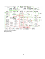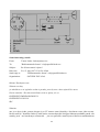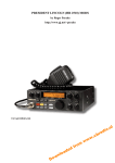
1
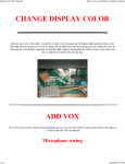
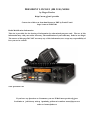
PRESIDENT LINCOLN (HR 2510) MODS
by Roger Perales
http://www.gj.net/~perales
Conversion of this text from html format to PDF by Frank Tomeš
http://come.to/329RC106
Radio Modification Information
This site is provided for the sharing of information for educational purposes only. The use of this
information may void your radios warranty, The modification of your radio may make its use illegal.
The owners of this page DO NOT warranty any of this information, nor accept any responsibility of
how you use its content.
www.president.com
If you have any Questions or Comments, you can E-Mail me at [email protected]
Jestli máte n jaké dotazy nebo p ipomínky, pošlete mi e-mail na [email protected]
nebo na [email protected]
Table of Contents
To convert the HR2510 to 11 Meter operation: ....................................................................................... 4
To convert the Lincoln to 11 Meter operation: ....................................................................................... 5
HR2510 Modification for increased MicGain .......................................................................................... 6
President or Uniden HR-2510 Variable Power Modification ................................................................. 7
Increasing the power output for the HR2510 ........................................................................................... 8
Modification of the HR2510 Mic buttons to operate the VFO ............................................................. 10
MOD # 1 ........................................................................................................................................ 10
MOD # 2 ........................................................................................................................................ 11
Talkback Removal..................................................................................................................................... 13
MOD #1 - The Relay Approach .................................................................................................. 13
MOD #2 - The Solid State Approach I ....................................................................................... 14
MOD #3 - The Solid State Approach II ...................................................................................... 15
HR2510 RIT / Clarifier Mods ................................................................................................................. 16
RIT MOD I ................................................................................................................................... 16
RIT MOD II .................................................................................................................................. 16
RIT MOD III ................................................................................................................................ 16
RIT MOD IV ................................................................................................................................. 17
HR2510 Misc. Enhancements. ................................................................................................................. 18
Increasing the Receive Audio I .................................................................................................... 18
Increasing the Receive Audio II .................................................................................................. 18
Increasing the Receive Audio III ................................................................................................ 18
Mute circuit improvement ........................................................................................................... 18
Roger Beep Mods .......................................................................................................................... 18
Adding an external meter to the HR2510 .................................................................................. 19
If you are really interested, I suggest trying the CHIPSWITCH. ....................................................... 20
24 MHZ Broadband instructions for your HR2510 .............................................................................. 21
MOD #1 ......................................................................................................................................... 21
MOD #2 A simpler method... ....................................................................................................... 22
HR2510 Alignment Instructions - (Taken from the Uniden Service Manual) ................................... 23
Alignment of P.L.L. and Carrier Oscillator Portion ................................................................. 23
Alignment of Transmitter Portion .............................................................................................. 24
Alignment of Receiver Portion .................................................................................................... 26
HR2510 Alignment and Test Point Layout ............................................................................................ 27
Synthesizer / Microprocessor / PLL PCB ................................................................................... 27
Main PCB....................................................................................................................................... 27
HR2510 Circuit Block Diagram............................................................................................................... 29
Microphone wiring.................................................................................................................................... 29
Some interesting e-mails ........................................................................................................................... 31
Subject:
Re: Kterou stanici vybrat ? .................................................................................. 31
Subject:
Re: Lincoln mods homepage ................................................................................ 32
Subject:
Mirror..................................................................................................................... 32
To convert the HR2510 to 11 Meter operation:
Remove the cover on the speaker side of the radio. You will need to loosen the 4 screws (2 on each side)
that secure the SYNTH PCB Frame to the chassi. - You do not need to remove these screws - You need
to remove the 4 screws that secure the SYNTH PCB to the metal frame.
Now flip the SYNTH PCB over, Locate the pins of the Microprocessor. In some versions of the HR2510
there may be Grey Epoxy covering one end of the Microprocessor. You may be able to peel the epoxy
right off to expose the pins of the IC. If it is not soft enough to peel off, you can use a 400W hair dryer
to heat the epoxy enough to remove it.
Cut the ground trace connected to pins 34 & 35, jump pins 34 & 35 to the free end of Resistor pack
RR301 (see diagram) or connect a 4.5K -15K ohm resistor from pins 34 & 35 to pin 3 of IC312 (5V
regulator).
This will give complete coverage from 26.000 MHz to 29.699 MHz (Some radios will go to 29.999
MHz)
4
To convert the Lincoln to 11 Meter operation:
Remove the cover on the speaker side of the radio..
Locate the the Microprocessor on the SYNTH PCB.
Tie a jumper wire from the thru plate via hole at the end of the trace the bare end of the 10K ohm
Resistor. (see diagram) or connect pins 34 & 35 together..
5
HR2510 Modification for increased MicGain
This mod will increase the AM modulation.
The AM modulation adjustment is VR114, which is marked >AMC= on the main circuit board.
To get more, Q114 is the Mic Attenuator, This limits the audio.
Q114 is located near the front of the circuit board in the center to the left of IC 104, above C153.
To modify this, remove Q114 and bend the Emmitter leg up from the circuit board and re install.
Put a 1000 ohm resistor in the vacant hole and solder to the board.
Solder the other end of the resistor to the Emitter leg of Q114.
This will allow more modulation with the >stock= mic, and will allow a Power Mic to truly
perform! The AMC control will still function so using a modulation meter you will be able to set it to
avoid overmodulation.
Another Mod Suggests Clipping D129 to remove the ALC and AM limiting. I have heard from
one user that this mod works exceptionally well.. I have not tried this mod, If anyone else has, please
let me know the results.
Send E-Mail to [email protected]
6
President or Uniden HR-2510 Variable Power Modification
The HR-2510 does not have a varible output power feature as it comes from the manufacturer. The following
modification will allow you to fix that oversight.
7
Increasing the power output for the HR2510
1). Remove the top and bottom covers.
2). Locate and remove Q132 & Q134.
3). Replace Q134 with an ECG 340 or TCG340.
WARNING!!! The leads of the two transistors are exactly opposite of each other.
[ 2SC2086 = BCE ; ECG340 = ECB.]
4). Replace Q132 with an MRF 497. ( Be sure to use heat sink compound.)
5). Remove C132. (no replacement)
6) Remove C112 & C116.
7). Replace C112 with an 82pf capacitor, But put the new Capacitor on the bottom of the PC board.
8). Replace C116 with an 100pf capacitor, But put the new Capacitor on the bottom of the PC board.
Component Layout with Cross reference for the HR2600
9). Connect power to the radio, and following the alignment procedures, adjust the bias of Q132 to
80mA +/- 5mA by adjusting VR112.
[To adjust the bias of Q132: Remove the B002(PB-100) jumper board from the Main PCB.
Connect a DC Ammeter (+) to TP4, (-) to TP3.
8
With the radio on USB, Adjust VR112 for 80mA +/- 5mA on the DC Ammeter.
After the adjustment is complete, Reinstall the B002(PB-100) jumper board. ]
10). inject a two tone signal into the microphone of the radio while transmitting into a dummy load.
Set VR104 (ALC) for maximum output..
Retune VR107 ( AM /FM carrier level) for Maximum.
Retune VR103(CW carrier level) for Maximum
11). Again inject a two tone signal into the microphone of the radio while transmitting into a dummy
load. Spread or contract coils L121 & L123 for the highest power out in the center of the band.
12). Replace the covers and the screws, you should now have between 50 and 100 watts on SSB.
This mod was originally written by M.T. Stacey, KC4HGH in an article published in CQ
magazine of September 1989 on page 48. There was also supposed to be an Update in >73 magazine
of November 1989 on page 76, Although I have never been able to find a copy to verify it.
9
Modification of the HR2510 Mic buttons to operate the VFO
Note:This modification is not needed if you have Chipswitched your radio already. The Chipswitch
does this internally.
What these mods do is to disconnect the 5Khz steps and allow the Mic buttons to do what the Rotary
switch does.
MOD # 1
The rotary switch applies 5 volts to activate the Up or Down control of the VFO.The Mic uses ground
to activate the 5 Khz step control of the Up or Down buttons.The changes to the Mic are required
because of these differences in the control operation.
The 1K resistor and 1N4001 diode combination causes the TX lead to be HI >5 volts= on receive and
it protects the 5volt source on TX when the lead is grounded. (You must use a 1N4001 diode, because
a 1N914 will not handle the current on TX).
Instructions:
1. Open the Mic and remove the ground from the Up and Down Switches and connect the common of
the switches to the TX lead. (see diagram below) Reassemble the Mic.
2. Remove both covers from the radio and look for the Mic jack. You will find 2 resistors, one on pin
#4 and the other on pin #5. Jump out both resistors with wire.
3. Find J308, located on the top left corner of the Microprocessor board. Cut the Yellow wire from the
connector, leaving enough to attach a 1N4001 diode to each end, anode to J308 side cathode to the Mic
jack. (see diagram below).
4. Add a 1K ohm resistor to the cathode of the 1N4001 diode and wire the opposite end to the rotary
switch, connect it to the etch on the back of the switch that does not have a Grey or White wire (Orange
or Brown in the Lincoln) on it. Usually the Violet wire (usually Red in the Lincoln).
5. Cut the Orange and Brown wires from J308 and route them to the rotary switch.
6. Connect a 1N914 diode across across the Grey and White wires (Brown and Orange in the Lincoln)
on the rotary switch. (see diagram below).
7. Connect the Brown wire, cut from J308, to the White wire (Orange in the Lincoln) on the back of
the rotary switch.
8. Connect the Orange wire, cut from J308, to the Grey wire (Brown in the Lincoln) on the back of the
rotary switch.
10
NOTE: If the Up / Down buttons work backwards, exchange the Orange and Brown wires.
MOD # 2
Mod #2 is the same principal as Mod #1, But uses a Solid State approach, and does not require rewiring
of the Microphone.
This Mod also allows for an automatic frequency increase or decrease as long as you hold the button
down.
The rotary switch applies 5 volts to activate the Up or Down control of the VFO.The Mic uses ground
to activate the 5 Khz step control of the Up or Down buttons.
Using a 4001 CMOS quad 2 input NOR gate, you can create a multivibrator to generate a pulsed
output to allow the >automatic= function of the mod. The rest of the 4001s gates are used as gated
inverters.
When the UP button is pressed it grounds pin 13, causing the pulse train on pin 12 to be outputed to
pin 11 through the isolation resistor to the white wire on J307, this will increment the frequency of the
selected digit on the HR2510, about 1 digit per pulse as long as the button is held down.
When the DOWN button is pressed it grounds pin 9, causing the pulse train on pin 8 to be outputed
to pin 10 through the isolation resistor to the grey wire on J307, this will decrement the frequency of
the selected digit on the HR2510, about 1 digit per pulse as long as the button is held down.
Instructions:
Refer to the Diagram below and create the circuit shown. You can use an experimenters perf board
from Radio Shack (P/N 276-158A) and there is ample room in the HR2510 to mount it inside.
Hookup:
1. Connect the brown wire cut from J308 to the input pin 13 on the 4001 CMOS IC.
2. Connect the orange wire cut from J308 to the input pin 9 on the 4001 CMOS IC.
11
3. Connect the output wire from the Isolation resistor on pin 11 of the 4001 CMOS IC to the top trace
on the frequency knob. (the white wire).
4. Connect the output wire from the Isolation resistor on pin 10 of the 4001 CMOS IC to the 2nd trace
from the top trace on the frequency knob. (the grey wire).
5. Connect the power wire to the 5 volt regulator pin 3 (facing the front of the radio, the far right leg
of the L78MO5CV, located in the middle of the microprocessor circuit board). [see diagram]
6. Connect the ground wire to a good circuit ground.(you can use the left rear screw on the
microporcessor board mounting).
After installation all the controls should work normally, and when pressing and holding the mic
buttons the frequency should slide up or down the band at about 2 increments a second.
If you have any questions, you can E-mail me. Although I have not tried this mod (MOD #2) it is fairly
straight forward.
12
Talkback Removal
MOD #1 - The Relay Approach
One method of Talkback removal is to break the speaker line with a relay.
Parts needed :
12Volt SPDT relay
2 - 1N4148 Diodes
1 - 1N 4001 Diode
Several pieces of hookup wire
Jumper the Relay coil - K1 with a 1N4001 Diode - D1. To key the relay you connect one side of the
Relay coil (the side with the Cathode of the diode) to IC107 pin 1.(HA17808W)
Cut the Blue wire that goes to pin 1 of the AUX plug on the rear of the radio. (Make sure you leave
enough wire to reconnect each end to wires for the relay.) Attach the wire from pin 1 of the AUX plug
to the Wiper contact of the Relay- K1. Attach the other half of the Blue wire to the Normally Closed
side of the Relay.
(Make sure you leave enough wire to reconnect each end to wires for the relay.)
Cut the Yellow wire from pin 3 of the Mic plug. Jumper the cut Yellow wire with a 1N4148 Diode - D2
(Cathode to the Mic Plug Pin 3) Connect the last 1N 4148 Diode - D3 to the Relay coil, Anode side to
the Anode of the Diode - D1 on the coil of the relay.Connect the Cathode to Pin 3 of the Mic
plug.(Cathode to Cathode of the two diodes on pin 3 of the Mic plug.)
13
MOD #2 - The Solid State Approach I
All that is needed is to add a 1N914 Diode from pin 6 of IC103 to the collector of Q125.
Connect the cathode of the diode to pin 6 of IC103, and the anode to the collector (the center pin) of
Q125.
14
15
MOD #3 - The Solid State Approach II
All that is needed is to add a 1N914 or a 1N4148 Diode connected to a 10k to 100k resistor from pin 6
of IC103 to the Base of Q127.
Connect the anode of the diode to one side of the resistor. Connect the other side of the resistor to pin
6 of IC103, and the cathode to the Base of Q127.
Note: Use a 10k ohm resistor if you only use the internal speaker. Use a 100k ohm resistor if you use
an external speaker.
These last 2 MODs remedies the Audio Feedback caused by the Audio Amplifier chip, IC103 (TDA
1905) not being switched over completely from RX to TX when you key the mike. These fixes rebias
the switiching transistor to correct this.
16
HR2510 RIT / Clarifier Mods
The RIT (Receiver Incremental Tuning) on the HR2510 is a Clarifier control to help >tune in= usually
SSB signals that may be transmitted off of center. The RIT only works on the receiver. The HR2510
does not allow >slide= on transmit unless its modified. Many people wish to >Open= the RIT (or
Clarifier).
Everyone has a different mod for this one, I will list the ones I know. Basically they are about the same,
You need to disconnect the existing voltage from the clarifier (RIT) circuit and add a constant voltage
to the clarifier (RIT) control circuit.
This voltage needs to be there during transmit.
RIT MOD I
Find D150 on the main circuit board. With the radio right side up, it will be found in the front
right-hand corner of the PCB.
Lift or clip one end of this diode.
Find the orange wire comming from the RIT/RF GAIN PCB (PB-120). From there it goes to the main
PCB to a 4 wire connector (Yellow/Orange/Red/Brown) located on the left side of the main PCB near
the center of the radio. Clip the orange wire from the connector and feed it through to the other side
of the radio. Solder it to pin 3 of IC 311. This will be a three-pin voltage regulator located just to the
right of the large microprocessor (IC315). The pins on IC 311 are numbered from left to right.
To center the RIT:
Locate the 3 tuning coils on the front left corner of the main PCB. The exreme left coil labeled L116,
adjusts USB. The center coil is labeled L118, adjusts LSB. The right coil labeled L117, adjusts CW.
There will be some interaction between the coil adjustments so you may need to repeat retuning a few
times. I suggest you start with the USB coil and end with the CW coil.
The Mod will give you plus or minus 3 Khz slide, the RIT will NOT change the display, but the
transmit and receive frequency will track together now.
RIT MOD II
Cut D150 on the main PCB. Locate the orange wire at the top of the RIT PCB, cut and connect to pin
3 of IC107. This is a 3 pin transistor bolted to the left side of the case next to VR116. Pin 3 is the lead
closest to the back of the radio. You now have +/- 5khz slide.
RIT MOD III
Find the orange wire comming from the RIT/RF GAIN PCB (PB-120). From there it goes to the main
PCB to a 4 wire connector (Yellow/Orange/Red/Brown) located on the left side of the main PCB near
the center of the radio. Clip the orange wire from the connector. Find the red wire (8 Volts) on the
mode switch PCB and solder the orange wire to it.
To Adjust:
Set the RIT to center (12 o=clock) Mode switch to AM Frequency to 28.000 Mhz.
Connect a Frequency counter to TP306. Adjust L315 for 6.200Mhz
17
Connect a Frequency counter to TP304. Adjust L318 for 38.695Mhz
Connect a frequency counter to TP1.
Set the Mode switch to USB, adjust L116 for 10.6975Mhz.
Set the Mode switch to LSB, adjust L118 for 10.6925Mhz
Set the Mode switch to CW, adjust L117 for 10.6950Mhz
Check RIT range. It should be +/- 4Khz
RIT MOD IV
Find the orange wire comming from the RIT/RF GAIN PCB (PB-120). From there it goes to the main
PCB to a 4 wire connector (Yellow/Orange/Red/Brown) located on the left side of the main PCB near
the center of the radio. Clip the orange wire from the connector. Solder the orange wire to Jumper 13
(JP13) +8V constant . Cut D150.
To center the RIT: With the Mode switch to AM, Frequency at 28.000Mhz, RIT at 12 o=clock, connect
a frequency counter to TP304, adjust L318 for 38.695Mhz.
HR2600 NOTE:
D150 is for the HR2510, D43 is for the HR2600, also in the HR2600 the wire may be orange or brown.
The
connector on the main PCB is a 5 wire connector.
18
HR2510 Misc. Enhancements.
Increasing the Receive Audio I
The HR2510 does not have a by-passed emmiter in the audio circuit. To correct this, Add a 4.7uf 16v
Electrolytic capacitor across (in Parallel) with R152 (a 560 ohm resistor). This modification will
increase the receive audio.
Increasing the Receive Audio II
This mod will increase the AM reception: Replace the AM Detector diodes (D111 & D112) with better
Schottky Barrier diodes. You can use ECG 583 or NTE 583 diodes or 1N6263 or equilvalent. (In the
HR2600 the diodes are labelled D11 & D12).
Increasing the Receive Audio III
This mod will increase receive strength and dynamic range, resulting in louder, cleaner signals while
actually reducing noise levels. All you need to do is to replace the existing IF Amp transistor with a new
one which has greater frequency response and lower noise characteristics. Once installed you will need
to adjust your AS@ meter for more realistic readings.
1.) Remove diode D101 and Transistor Q101.
2.) Replace Q101 with a ECG or NTE 23.
NOTE: The new transistor has a different pin out from the original. You will need to reorient the new
transistor to work. With the flat side of the transistor facing you and leads pointing down : Exixsting
leads of Q101 = 1 2 3 , the replacement ECG or NTE, you will need to cross the first lead to the last =
231.
Mute circuit improvement
To Improve the operation of the Mute circuit, remove C139 and R199. These two components are
connected to the base of Q117.
Roger Beep Mods
The Roger Beep in the HR2510 is >Unique= but kind of wimpy..To modify this, locate R96 (a 2.7 Meg.
ohm resistor).
Remove and replace with a 100K ohm 1/8 watt resistor. This will increase the amplitude of the beep.
To change the duration (length) of the beep, replace C110 (10uf 16v ) remove and replace with a
capacitor at least 50v with more or less capacitance to lengthen or shorten the beep to your preference.
These components are located to the left (facing the front of the radio) of IC 104.
Component location diagram
19
Adding an external meter to the HR2510
To add a needle type meter all you need to do is connect it to C302 on the Microprocessor.
20
If you are really interested, I suggest trying the CHIPSWITCH.
It gives you :
1) 30 memory channels, with temporary channel lockout and repeater offsets.
2) Extended frequrncy covreage - 24.800 to 29.999 Mhz.
3) Programmable Scan/Seek functions. Scan-This allows you to set a range of frequencys in any band,
and even set the hold time during scans.
Seek-This causes the radio to seek for active channels. both features are programmable from 5khz or
10 Khz steps.
4) Programmable channel up and down buttons. This is the ability to program the radios channel up
and down button to change channels/freq. in any one of 5 different ways (5Khz, 10Khz, underlined
digit, etc.).
5) Programmable Mic channel up and down buttons. This allows programming the mic up/down
buttons in any of 8 different ways.
6) Split freq operation.
7) programmable Xmit time out.(a built in QSO timer)
8) Programmable transmit freq. range.
9) Span underline cursor- allows 100Khz steps on the channel buttons, And the underlined digit can
be changed with the Mic Buttons.
10) Programmable button repeat.
11) Programmable button beep duration.
12) (in the 2600) RPTR button will toggle the xmit of CTCSS tones from a memory channel.
This is a very versatile update. It does require the ability to remove the Microprocessor and solder in
a new one. But it is fairly easy with a little soldering experience, and the right tools.
It comes with a complete manual and installation instructions. The cost from the manufacturer is now
only $49.95, and its availiable from copper electronics, if you want to go that way (I think Copper
charges $69.99).
Chipswitch can be ordered by Phone directly from the manufacurer, there address is:
CHIPSWITCH
4773 Sonoma Hwy. Suite 132
Santa Rosa, Ca. 95409-4269
Phone: (707) 539-0512 (answering machine for orders and info)
or you can visit their Website at: www.chipswitch.com
You can call them and order an information sheet prior to ordering the Chipswitch.
I reccommend this mod highly! Its easy and it does not require any new switches. It uses all the existing
switches and buttons.
21
24 MHZ Broadband instructions for your HR2510
These instructions are to broadband your radio if you have the 24.000Mhz mod or the ChipSwitch
installed.
MOD #1
1. Take the four screws out of the speaker cover on the radio.
2. With the radio upside down and the PLL board facing you, Remove the four screws in each corner
of the pll board.
3. Loosen the four screws on the sides of the radio that hold the PLL tray in the radio. Loosen them
all the way before they come completely out.
4. Pull the PLL board out towards you so the bottom of the PLL board is upside down.
5. Look at the diagram below and locate C304, C326, & C327. At the point where they connect
together, you will place 1 leg of a 50V 220pf capacitor (Radio Shack P/N 272-124) and the other leg to
Ground of the board.
6. Check your work and make sure you did not short anything out and that you placed the capacitor
in the right place.
7. Reassemble the PLL board and connect power to the radio.
8. Connect a watt meter and a dummy load to the antenna jack.
9. Put the radio on 29.500.Mhz and peak L310 for maximum output power.
10. Now put the radio on 25.500Mhz and peak L319 for maximim output power.
11. Reassemble your radio and your ready to go.
22
MOD #2 A simpler method...
Here is a simpler method of increasing the VCO coverage on the HR2510. If your HR2510 is
Chipswitched, but doesn't lock on 12 Meters, this mod will take care of the problem without having
to access the underside of the synth PCB.
Remove the four screws from the bottom cover and remove the cover.
On the PLL board locate L307 (TP306).
Install a small ceramic capacitor between the long lead of L307 and ground. Any value between 180
and 220 picofarad (pf) will do. There is a convenient ground loacted just behind L307. this locationis
a plate-through hole (it looks like a shiny solder dot showing through the silk screening.)
The set should now lock from 24.800 to 29.900Mhz without further adjustment.
If you have access to a scope, the radio can easily be broadbanded for better performance in this new
frequency range. to broadband, monitor the output at J311 and adjust L310 and L319 for equal output
at the upper and lower limit of your operating range.
23
HR2510 Alignment Instructions - (Taken from the Uniden Service Manual)
Alignment of P.L.L. and Carrier Oscillator Portion
1. Test equipment required:
DC Power supply (13.8V)
DC Voltmeter
Dummy Load (50 Ohm)
Frequency Counter
Oscilloscope
2. Preperation for Alignment:
PA SW : Off
Mode SW : AM
RIT : Middle Position
TX SW : Off
3. Alignment Procedure:
1
Preset to:
Adjust
ment
Remarks
Mode : RX, AM
L315
Connect an oscilloscope to TP306.
SG : 28MHz
2
Ditto
Adjust L315 For 6.200MHz +/- reading on the oscilloscope.
L318
Connect the oscilloscpe to TP304.
Adjust L318 for 38.695MHz +/- 20Hz reading on the
oscilloscope.
3
Mode : RX, AM
SG : 29.6999
MHz
L317
Mode : RX, CW
SG : 28 MHz
L117
5
Mode : RX,
LSB
L118
Adjust L118 for 10.6925MHz (-40Hz to +0Hz) reading on the
oscilloscope).
6
Mode : RX,
USB
L116
Adjust L116 for 10.6975MHz +/- 20 Hz reading on the
oscilloscope.
7
Mode : RX,
USB
VR111
Connect the oscilloscope to TP5.
4
Connect a DC Voltmeter to TP303.
Adjust L317 for 6.5 +/- 0.1V reading on the Dc Voltmeter.
Connect the oscilloscope to TP1.
Adjust L117 for 10.6950MHz +/- 20Hz reading on the
oscilloscope.
Adjust VR111 for 38.6975MHz +/- 20 Hz reading on the
oscilloscope
24
Alignment of Transmitter Portion
1. Test equiptment required:
DC Power supply (13.8V) more than 10A
AF S.S.G. AM FM (1kHz, 500Hz and 2400Hz)
RF VTVM
Oscilloscope
DC Ammeter
RF Power Meter
AF VTVM
Dummy Load (50 Ohm)
FM Linear Detector
2. Preperation for Alignment:
VR112 : Clockwise
PA SW : Off
VR113 : Counter Clockwise
Meter SW : RF
VR103 : Clockwise
MicGain SW : Off
SWR/CAL : Middle Position
TX SW : Off
Freq. : 28.000 MHz
3. Alignment Procedure:
1
Preset to:
Adjustmen
t
Remarks
Mode:USB
VR112
Remove the B002(PB-100) from the Main PCB.
No Mod.
Connect a DC Ammeter (+) to TP4, (-) to TP3.
Adjust VR112 for 50mA reading on the DC Ammeter.
2
Ditto
VR113
Connect a DC Ammeter (+) to TP4, (-) to TP2.
Adjust VR113 for 50 mA reading on DC Ammeter.
3
1mV Mod.
L111
Disconnect DC Ammeter. Reinstall the B002 to the Main PCB.
Connect A RF Power meter to the ANT. jack. Connect a RF
VTVM, an oscilloscope and a FM Linear Detector across a RF
Dummy Load to the RF Power meter.
Adjust L111 for maximum reading on the RF VTVM.
During this step, set the AF oscillator so that the output is less
than 20V.
Repeat this two times.
25
4
30 mV Mod.
VR104
Adjust VR104 for 32.5V reading on the RF VTVM.
5
Ditto
VR106
Adjust VR106 so that the carrier leakage at USB and LSB
becomes minimum and almost equal.
6
Mode: CW
VR103
Connect a SW between Pin 8 and 9 of the ACC connector.
No Mod.
7
Mode: AM
With the SW turned on, adjust VR103 for 21W reading on the
Power meter.
VR107
Adjust VR107 for 10W reading on the RF power meter.
No Mod.
8
Ditto
VR117
Adjust VR117 so that "9" LCD just lights on.
9
1 kHz, 30mV
Modulation
VR114
Adjust VR114 to obtain the 85% negative reading on the
oscilloscope.
10
1kHz, 1mV
Modulation
VR115
Adjust VR115 so that "9" LCD just lights on.
VR105
Adjust VR105 for +/- 3kHz deviation reading on the FM
Linear Detector.
VR116
Connect a AF VTVM across a dummy load (8 Ohm) between
Pin 1 and Pin 2 of the ACC connector. With the SW turned
on, adjust VR116 for 0.4V negative reading on the AF VTVM.
INDIC:
MOD
11
Mode: FM
1kHz, 30mV
Modulation
12
Mode: CW
No Mod.
Vol. : Max
26
Alignment of Receiver Portion
1. Test equiptment required:
AF VTVM
DC Power supply (13.8V)
Oscilloscope
Dummy Load (50 Ohm)
S.S.G. AM FM (28.000MHz, 1KHz, 30% Mod. and 50 Ohm Impedance)
2. Preperation for Alignment:
NB SW : Off
Mode : AM
PA SW : Off
Squelch : Min. (Auto SQ Off)
Beep SW : Off
RF Gain : MAX
VOLUME : MAX
TX SW : Off
RIT : Middle position
3. Alignment Procedure:
Preset to:
1
2
Adjustment
Remarks
L101, L104,
L113,
L115, and
L105
Alignment of sensitivity
VR102
Alignment of Squelch
Adjust coils for maximum reading of the AF VTVM. (During
this step, set the S.S.G.attenuator so that the standard output
is less than 0.5W (2v/8ohm)).
Set th output of the S.S.G. to 66dB +/- 2dB and squelch to
maximum. Adjust VR102 so that squelch just breaks.
3
VR101
Alignment of S-Meter
Set the output of the S.S.G. to 46dB, no modulation.
Adjust VR101 so that "9" LCD just lights on.
4
Mode : FM
S.S.G. : 1mV
L401
Adjust L401 for maximum reading on AF VTVM.
L203
Adjust L203 for minimum reading on the AF VTVM.
(1.5kHz Dev.)
5
Mode : AM
Noise GEN.
to the ANT
Jack.
(Noise GEN. OUTPUT : 50Hz SQ Wave 2Vp-p)
27
HR2510 Alignment and Test Point Layout
Refer to the HR2510 Alignment instructions
(The colors correspond to the adjustment procedure)
Synthesizer / Microprocessor / PLL PCB
28
Main PCB
29
HR2510 Circuit Block Diagram
Microphone wiring
30
Some interesting e-mails
From:
Tomas Laska <[email protected]>
To:
"Radioamaterske forum" <[email protected]>
Subject:
Re: Kterou stanici vybrat ?
Date sent:
Fri, 15 Aug 1997 12:28:54 +0200
Send reply to:
"Radioamaterske forum" <[email protected]>
Organization:
SATURN-TOYA Ltd.
Bohous' Darbujan wrote:
Zdravim vsechny,
jiz nekolikrat se mi vyplatilo nechat si poradit, proto by mne i dnes zajimal Vas nazor:
Kterou stanicku ? Do dnes mam Gianta, neni to spatny, ale co
PREZIDENT EMPEROR SHOGUN
PREZIDENT LINCOLN
IRC.
Zdravim
ono je to skoro jedno, protoze shogun je po VF strance temer identicky s lincolnem vcetne jeho nesvaru.
hlavni rozdil je v komfortu. linkos je stara stanice a tomu odpovida i design a funkcnost predniho panelu. obe
stanicky jsem mel rozebrany a na meracich - jen se to potvrdilo. zameril jsem se hlavne na mezikanalovou
31
selektivitu, citlivost, potlaceni AM a zrcadla. shogun je na tom o neco lepe (provedli nejaka vylepseni). linkos
je trochu sirsi a tudis mene vhodny pro provoz na CB pasmu v FM. tyhle stanice jsou obvodove predurcene
pro SSB. da se znich vyzdimat pres 30W. Bohuzel dost trpi na koncovy stupen - taky dost zere a topi. Pokud
chces excelentni stanici pro provoz na CB a SSB (nedostizna selektivita, dvojciny koncak atd...) kup si
presidenta GEORGE (budes ale muset trochu pritlacit ;) GEORGE ale nechodi do 30MHz a nejmensi krok
je 5kHz. to neni az tak na zavadu, pokud nejses profik, vetsina zajimaveho SSB provozu pro normalni lidi
se odehrava na "D" bandu (tedy dalsich 40K nad CB a take na "B") kdyz nemas licenci, tak se stebou nahore
(od 28MHz vejs) nebude nikdo bavit.
moderator necht odpusti, ze davam reply do konference, ale myslel jsem, ze by to mohlo jeste nekoho zajimat.
btw kdyz je tu pomerne klid ;)
Tomas Stresovice
32
From:
Self <Single-user mode>
To:
[email protected]
Subject:
Re: Lincoln mods homepage
Date sent:
Sat, 11 Apr 1998 11:08:47 +0100
Hi Roger,
you wrote:
> I would not mind if you wish to Mirror my site. If you need any help with the files, let me know.
> Are you going to try to translate it into Czech? That would be interesting!
Yes, I want to translate this pages into Czech. It can very help to our local Lincoln`s users. But, I want to have
your permission that I can do it and publish it on my web pages. I don't want do something without permission
or publication of author`s name. (I saw a lots of sites which contained grabbed or stollen material without
survey`s publication of course).
I am looking forward your reply.
73 Frank
Date sent:
Sat, 11 Apr 1998 16:30:42 -0600
From:
Perales <[email protected]>
To:
[email protected]
Subject:
Mirror...
Frank,
Yes! Feel free to mirror my site. Please include My web address somewhere on your site as well. I can send
the pages to you via E-mail if you wish. That may help in your conversion.
Please send me your web page address when you get it finished, and I'll put it on my site as well.
Roger
From: Self <Single-user mode>
To:
[email protected]
Subject:
lincoln web in Czech
Date sent:
Sun, 12 Apr 1998 20:56:05 +0100
Hi Roger,
thanks a lot for your permission, it is very important for me. Please send me your web pages in html format
(or if you have it in some word processor writed) and the pictures in the gif or jpeg format. All it can be in
a zip or arj archive, I will translate it into Czech language and I will put it on my DX homepage, its url is
http://come.to/329RC106 that it is my personal 11 meters band homepage.
73 Frank (329 RC 106) I hope you are not worried I am not a radio amateur but 11m band pirate :-)
33