1
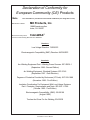
IM774
GMAW
Push-Pull Gun
MK 091-0525
December 2006
Rev. E
OPERATOR'S MANUAL
CobraMAX™
Model numbers K2252-1 & K2252-2
This manual covers equipment which is no
longer in production by The Lincoln Electric Co.
Specifications and availability of optional
features may have changed.
Safety Depends on You
Lincoln arc welding equipment
is designed and built with safety
in mind. However, your overall safety can be increased by
proper installation...and thoughtful
operation on your part. DO NOT
INSTALL, OPERATE OR REPAIR
THIS EQUIPMENT WITHOUT
READING THIS MANUAL AND
THE SAFETY PRECAUTIONS
CONTAINED THROUGHOUT.
And, most importantly, think before
you act and be careful.
OPERATOR’S MANUAL
Copyright © 2006 Lincoln Global Inc.
World's Leader in Welding and Cutting Products
Sales and Service through Subsidiaries and Distibutors Worldwide
Cleveland, Ohio 44117-1199 U.S.A. TEL: 216.481.8100 FAX: 216.486.1751 WEB SITE: www.lincolnelectric.com
Table of Contents
Safety Considerations
Installation................................................................................ Section A
Technical Specifications......................................................................................1
Support Equipment Required..............................................................................1
Coolant Recommendations.................................................................................1
Gun Lead Connections.......................................................................................1
Operation..................................................................................Section B
General...............................................................................................................2
Controls and Settings..........................................................................................2
Drive Roll and Idler Rolls....................................................................................3
Accessories..............................................................................Section C
Optional Kits........................................................................................................4
Conduits..............................................................................................................4
Snake Skins........................................................................................................4
Contact Tips........................................................................................................5
Gas Cups............................................................................................................5
Maintenance.............................................................................Section D
Periodic Maintenance.........................................................................................6
Maintenance Tools..............................................................................................6
Recommended Spare Parts List.........................................................................6
Troubleshooting........................................................................Section E
Troubleshooting Guide........................................................................................8
Testing The Gun..................................................................................................8
Appendices...............................................................................Section F
Diagrams / Parts List...........................................................................................9
Mechanical........................................................................................................10
Electrical...........................................................................................................15
Safety Warnings
Warranty
CobraMAX™ Owner's Manual
Declaration of Conformity for
European Community (CE) Products
Note
This information is provided for units with CE certification (see rating label on unit).
Manufacturer’s Name:
MK Products, Inc.
16882 Armstrong Ave.
Irvine, CA 92606
Declares that the product:
CobraMAX™
conforms to the following Directives and Standards:
Directives
Low Voltage Directive: 73/23/EEC
Electromagnetic Compatibility (EMC) Directive: 89/336/EEC
Standards
Arc Welding Equipment Part I: Welding Power Sources: IEC 60974-1
(September 1998 - Second Edition)
Arc Welding Equipment: Wirefeed Systems: IEC 974-5
(September 1997 - Draft Revision)
Degrees of Protection Provided by Enclosures (IP Code): IEC 529:1989
(November 1989 - First Edition)
Insulation Coordination For Equipment With Low-Voltage Systems:
Part I: Principles, Requirements and Tests: IEC 664-1: 1992
(October 1992 - First Edition)
Electromagnetic Compatibility, (EMC): EN 50199
(August 1995)
Torches And Guns For Arc Welding, EN 50078
CobraMAX™ Owner's Manual
CobraMAX™ Owner's Manual - Page SAFETY
ii
ARC RAYS can burn.
ELECTRIC SHOCK can
kill.
3.a. The electrode and work (or ground) circuits
are electrically “hot” when the welder is on.
Do not touch these “hot” parts with your bare
skin or wet clothing. Wear dry, hole-free
gloves to insulate hands.
3.b. Insulate yourself from work and ground using dry insulation.
Make certain the insulation is large enough to cover your full
area of physical contact with work and ground.
In addition to the normal safety precautions, if welding
must be performed under electrically hazardous
conditions (in damp locations or while wearing wet
clothing; on metal structures such as floors, gratings or
scaffolds; when in cramped positions such as sitting,
kneeling or lying, if there is a high risk of unavoidable or
accidental contact with the workpiece or ground) use
the following equipment:
• Semiautomatic DC Constant Voltage (Wire) Welder.
• DC Manual (Stick) Welder.
• AC Welder with Reduced Voltage Control.
3.c. In semiautomatic or automatic wire welding, the electrode,
electrode reel, welding head, nozzle or semiautomatic
welding gun are also electrically “hot”.
3.d. Always be sure the work cable makes a good electrical
connection with the metal being welded. The connection
should be as close as possible to the area being welded.
3.e. Ground the work or metal to be welded to a good electrical
(earth) ground.
3.f. Maintain the electrode holder, work clamp, welding cable and
welding machine in good, safe operating condition. Replace
damaged insulation.
3.g. Never dip the electrode in water for cooling.
3.h. Never simultaneously touch electrically “hot” parts of
electrode holders connected to two welders because voltage
between the two can be the total of the open circuit voltage
of both welders.
3.i. When working above floor level, use a safety belt to protect
yourself from a fall should you get a shock.
3.j. Also see Items 6.c. and 8.
ii
4.a. Use a shield with the proper filter and cover
plates to protect your eyes from sparks and
the rays of the arc when welding or observing
open arc welding. Headshield and filter lens
should conform to ANSI Z87. I standards.
4.b. Use suitable clothing made from durable flame-resistant
material to protect your skin and that of your helpers from
the arc rays.
4.c. Protect other nearby personnel with suitable, non-flammable
screening and/or warn them not to watch the arc nor expose
themselves to the arc rays or to hot spatter or metal.
FUMES AND GASES
can be dangerous.
5.a. Welding may produce fumes and gases
hazardous to health. Avoid breathing these
fumes and gases. When welding, keep
your head out of the fume. Use enough
ventilation and/or exhaust at the arc to keep
fumes and gases away from the breathing zone. When
welding with electrodes which require special
ventilation such as stainless or hard facing (see
instructions on container or MSDS) or on lead or
cadmium plated steel and other metals or coatings
which produce highly toxic fumes, keep exposure as
low as possible and below Threshold Limit Values (TLV)
using local exhaust or mechanical ventilation. In
confined spaces or in some circumstances, outdoors, a
respirator may be required. Additional precautions are
also required when welding on galvanized steel.
5. b. The operation of welding fume control equipment is affected
by various factors including proper use and positioning of
the equipment, maintenance of the equipment and the specific welding procedure and application involved. Worker
exposure level should be checked upon installation and
periodically thereafter to be certain it is within applicable
OSHA PEL and ACGIH TLV limits.
5.c. Do not weld in locations near chlorinated hydrocarbon vapors
coming from degreasing, cleaning or spraying operations.
The heat and rays of the arc can react with solvent vapors to
form phosgene, a highly toxic gas, and other irritating products.
5.d. Shielding gases used for arc welding can displace air and
cause injury or death. Always use enough ventilation,
especially in confined areas, to insure breathing air is safe.
5.e. Read and understand the manufacturerʼs instructions for this
equipment and the consumables to be used, including the
material safety data sheet (MSDS) and follow your
employerʼs safety practices. MSDS forms are available from
your welding distributor or from the manufacturer.
5.f. Also see item 1.b.
AUG 06
CobraMAX™ Owner's Manual - Page ii
SAFETY
iii
WELDING and CUTTING
SPARKS can
cause fire or explosion.
6.a. Remove fire hazards from the welding area.
If this is not possible, cover them to prevent
the welding sparks from starting a fire.
Remember that welding sparks and hot
materials from welding can easily go through small cracks
and openings to adjacent areas. Avoid welding near
hydraulic lines. Have a fire extinguisher readily available.
6.b. Where compressed gases are to be used at the job site,
special precautions should be used to prevent hazardous
situations. Refer to “Safety in Welding and Cutting” (ANSI
Standard Z49.1) and the operating information for the
equipment being used.
6.c. When not welding, make certain no part of the electrode
circuit is touching the work or ground. Accidental contact
can cause overheating and create a fire hazard.
6.d. Do not heat, cut or weld tanks, drums or containers until the
proper steps have been taken to insure that such procedures
will not cause flammable or toxic vapors from substances
inside. They can cause an explosion even though they have
been “cleaned”. For information, purchase “Recommended
Safe Practices for the Preparation for Welding and Cutting of
Containers and Piping That Have Held Hazardous
Substances”, AWS F4.1 from the American Welding Society
(see address above).
6.e. Vent hollow castings or containers before heating, cutting or
welding. They may explode.
6.f. Sparks and spatter are thrown from the welding arc. Wear oil
free protective garments such as leather gloves, heavy shirt,
cuffless trousers, high shoes and a cap over your hair. Wear
ear plugs when welding out of position or in confined places.
Always wear safety glasses with side shields when in a
welding area.
6.g. Connect the work cable to the work as close to the welding
area as practical. Work cables connected to the building
framework or other locations away from the welding area
increase the possibility of the welding current passing
through lifting chains, crane cables or other alternate circuits. This can create fire hazards or overheat lifting chains
or cables until they fail.
6.h. Also see item 1.c.
6.I. Read and follow NFPA 51B “ Standard for Fire Prevention
During Welding, Cutting and Other Hot Work”, available
from NFPA, 1 Batterymarch Park,PO box 9101, Quincy, Ma
022690-9101.
iii
CYLINDER may explode
if damaged.
7.a. Use only compressed gas cylinders
containing the correct shielding gas for the
process used and properly operating
regulators designed for the gas and
pressure used. All hoses, fittings, etc. should be suitable for
the application and maintained in good condition.
7.b. Always keep cylinders in an upright position securely
chained to an undercarriage or fixed support.
7.c. Cylinders should be located:
• Away from areas where they may be struck or subjected to
physical damage.
• A safe distance from arc welding or cutting operations and
any other source of heat, sparks, or flame.
7.d. Never allow the electrode, electrode holder or any other
electrically “hot” parts to touch a cylinder.
7.e. Keep your head and face away from the cylinder valve outlet
when opening the cylinder valve.
7.f. Valve protection caps should always be in place and hand
tight except when the cylinder is in use or connected for
use.
7.g. Read and follow the instructions on compressed gas
cylinders, associated equipment, and CGA publication P-l,
“Precautions for Safe Handling of Compressed Gases in
Cylinders,” available from the Compressed Gas Association
1235 Jefferson Davis Highway, Arlington, VA 22202.
FOR ELECTRICALLY
powered equipment.
8.a. Turn off input power using the disconnect
switch at the fuse box before working on
the equipment.
8.b. Install equipment in accordance with the U.S. National
Electrical Code, all local codes and the manufacturerʼs
recommendations.
8.c. Ground the equipment in accordance with the U.S. National
Electrical Code and the manufacturerʼs recommendations.
Jan, 07
6.j. Do not use a welding power source for pipe thawing.
CobraMAX™ Owner's Manual - Page iii
CobraMAX™ Owner's Manual - Page iv
CobraMAX™ Owner's Manual - Page Thank You
for selecting a QUALITY product by Lincoln Electric. We want you
to take pride in operating this Lincoln Electric Company product
••• as much pride as we have in bringing this product to you!
CUSTOMER ASSISTANCE POLICY
The business of The Lincoln Electric Company is manufacturing and selling high quality welding equipment, consumables, and cutting equipment. Our challenge is to meet the needs of our customers and to exceed their expectations. On occasion, purchasers may ask Lincoln
Electric for advice or information about their use of our products. We respond to our customers based on the best information in our possession at that time. Lincoln Electric is not in a position to warrant or guarantee such advice, and assumes no liability, with respect to such information or advice. We expressly disclaim any warranty of any kind, including any warranty of fitness for any customerʼs particular purpose,
with respect to such information or advice. As a matter of practical consideration, we also cannot assume any responsibility for updating or
correcting any such information or advice once it has been given, nor does the provision of information or advice create, expand or alter any
warranty with respect to the sale of our products.
Lincoln Electric is a responsive manufacturer, but the selection and use of specific products sold by Lincoln Electric is solely within the control
of, and remains the sole responsibility of the customer. Many variables beyond the control of Lincoln Electric affect the results obtained in
applying these types of fabrication methods and service requirements.
Subject to Change – This information is accurate to the best of our knowledge at the time of printing. Please refer to www.lincolnelectric.com
for any updated information.
Please Examine Carton and Equipment For Damage Immediately
When this equipment is shipped, title passes to the purchaser upon receipt by the carrier. Consequently, Claims
for material damaged in shipment must be made by the purchaser against the transportation company at the
time the shipment is received.
Please record your equipment identification information below for future reference. This information can be
found on your machine nameplate.
Product _________________________________________________________________________________
Model Number ___________________________________________________________________________
Code Number or Date Code_________________________________________________________________
Serial Number____________________________________________________________________________
Date Purchased___________________________________________________________________________
Where Purchased_________________________________________________________________________
Whenever you request replacement parts or information on this equipment, always supply the information you
have recorded above. The code number is especially important when identifying the correct replacement parts.
On-Line Product Registration
- Register your machine with Lincoln Electric either via fax or over the Internet.
• For faxing: Complete the form on the back of the warranty statement included in the literature packet
accompanying this machine and fax the form per the instructions printed on it.
• For On-Line Registration: Go to our WEB SITE at www.lincolnelectric.com. Choose “Quick Links” and then
“Product Registration”. Please complete the form and submit your registration.
Read this Operators Manual completely before attempting to use this equipment. Save this manual and keep it
handy for quick reference. Pay particular attention to the safety instructions we have provided for your protection.
The level of seriousness to be applied to each is explained below:
WARNING
This statement appears where the information must be followed exactly to avoid serious personal injury or loss of life.
CAUTION
This statement appears where the information must be followed to avoid minor personal injury or damage to this equipment.
CobraMAX™ Owner's Manual
Section A Installation
Technical Specifications
Wire Capacity
.030" - .045" (0.6mm - 1.2mm) solid and hard wire
.030" - 1/16" (0.8mm - 1.6mm) aluminum and cored wire
Wire Speed
800 IPM (20.3 mpm) Max at rated feeder input voltage (120VAC / 42VAC)
Duty Cycle
All ratings are using Argon gas
200 Amps/25 Volts
250 Amps/25 Volts
Air cooled - 60%
Water cooled - 60%
Support Equipment Required
• C.V. or C.C. power source of sufficient capacity for your needs.
• Regulated gas supply and hoses.
•
Properly sized power leads from power source to wire feeder and
ground.
• Water source and hose capable of providing a minimum of 1 quart
(.95 liter) / min. at 45 psi when using water cooled guns.
Coolant Recommendations
Use a name-brand additive, which does not contain reactive sulphur or
chlorine and does not react with copper, brass or aluminum or create a
custom mix using this formula:
Use 3 Gallons (11.4 Liters) Distilled water.
Use 1 Gallon (3.8 Liters) ethylene glycol.
Use 1 tsp (5 ml) liquid glycerin
The Coolant rate should be 1 quart (.95 liter) / minute at 35 p.s.i.
Gun Lead Connections
Power Cable - Air Cooled
A #2 AWG power cable is used on the CobraMAX™ air cooled gun. The gun
end is threaded into the gun body with torque requirments of 100+5 in-lb.
The power cable fitting connects to the power block in the Cobramatic® wire
feed cabinet.
Power Cable - Water Cooled
The CobraMAX™ water cooled gun utilizes a power/water cable with a #4
AWG cable inside a 5/8” (16MM) diameter hose. The gun end is threaded
into the gun body with torque requirements of 100+5 in-lb.
IMPORTANT
Water cooled guns MUST be WATER cooled.
Conduit
The CobraMAX™ gun comes standard with a poly-lined conduit, for feeding
aluminum wire. The longer fitting with a shallow groove is used on the gun
end. A set screw located on top of the gun handle secures the conduit in
place.
CobraMAX™ Owner's Manual - Page Gas Hose
The gas hose is secured over the barbed gas fitting with a tie wrap. The
cabinet end of the gas hose uses our standard gas fitting (1/8” - 27 nps).
Water Hose
If so equipped, one end of the water hose is secured over the barbed water
fitting with a tie wrap and the other end is connected to the center fitting on
the power block.
Electric Cable
A seven conductor control cable is used on the CobraMAX™ gun. The gun
end of the control cable is secured to the gun with a boot clamp and soldered
to the pot assembly, tirgger and water leads. Slack is left in the electric cable
as it exits the back of the gun to prevent cable breakage. The cabinet end
has a seven pin “W” clocked amphenol connector.
Section B Operation
General
The CobraMAX™ gun maintains a constant, steady, uniform wire feed speed,
regardless of curved or looped wire conduit. The constant push exerted
by the slave motor in the cabinet, combined with the pull of the gun motor,
causes the wire to literally float friction-free through the wire conduit. The
24VDC gun motor is controlled by a three and three-quarter (3 3/4) turn
potentiometer in the gun handle.
Controls and Settings
Potentiometer
The laterally-positioned potentiometer is located in the lower end of the
handle, providing up to 800 ipm with 3 3/4 turns.
Micro Switch
The micro switch assembly consists of the micro switch and leads.
Trigger Sensitivity
The amount of trigger level travel can
be shortened for a "quicker" or "more
responsive" action.
A more sensitive trigger lever is
produced by reducing the gap between
the trigger lever and the micro switch
lever. By turning-in the trigger sensitivity
adjustment screw, it closed the gap
between the trigger lever and the micro
switch lever.
This will enable the operator to increase
the sensitivity of the trigger lever.
Sensitivity Adjustment
With the wire feeder turned on (with
or without welding wire loaded), turn
the screw in until the micro-switch is
activated. Once activated, the tortch and
wire feeder motors will begin feeding
wire. Retract the screw accordingly until
the system is deactivated and adjusted to
the operators' liking.
CobraMAX™ Owner's Manual - Page Drive Roll and Idler Rolls
General
The CobraMAX™ gun comes standard with a knurled drive roll and a grooved
idler roll, which will handle both steel and aluminum wire with diameters from
.030-1/16 inch. Optional insulated V-groove drive rolls are also available for
aluminum wire if desired (see optional kits).
Drive roll tension is accomplished with a unique spring-loaded pressure
screw. The CobraMAX™ comes from the factory with the pressure
adjustment screw preset. NO ADJUSTMENT is required for
all sizes and types of wires.
Drive Roll Installation/Removal
Note:
Neither of the handles needs to be removed to access the
drive or idler rolls
1. Pull the cam lever away from the idler roll. This will relieve the pressure
against the drive roll (as shown in Figure 1).
2. Align the drive roll removal tool (P/N 931-0100) over the flats of the drive
roll (as shown in Figure 2). Hold the gun with one hand or on a table
top, with the other hand give the removal tool a quick snap-turn in the
CLOCKWISE DIRECTION.
3. Once the drive roll is loose, continue to spin drive roll in the clockwise
direction to remove the drive roll from the gun.
4. Install a new drive roll on the left-hand threaded shaft. The drive roll will
self-tighten when it is feeding wire.
Cam Lever
Figure 2
Figure 1
Idler Roll Installation and Removal
(Reference Figure 3)
1. Using a slot type screwdriver, loosen idler screw, taking care not to lose
lock washer under idler roll.
2. Insert new idler roll and lock washer onto screw, insuring that idler groove
is toward top and lock washer is beneath.
Figure 3
3. Tighten.
NOTE: Lock washer must be under idler roll or it will not turn freely.
CobraMAX™ Owner's Manual - Page Section C Accessories
LE P/N
MK P/N
Optional Kits
Insulated Drive Roll Kits are used to prevent preheating of the wire which
may soften it and clog the liner. This picking up of current at the drive rolls
rather than at the contact tip is usually not a problem unless using too large
of a contact tip or excessively oxidized aluminum wire.
Insulated Groove Drive Roll Kit........................... KP1594-030........ 005-0640
For .030" (0.8mm) dia. aluminum wire. Includes insulated groove drive roll
and insulated idler roll assy.
Insulated Groove Drive Roll Kit........................... KP1594-035........ 005-0716
For .035" (0.9mm) dia. aluminum wire. Includes insulated groove drive roll
and insulated idler roll assy.
Insulated Groove Drive Roll Kit.................................. N/A............... 005-0642
For .040" (1.0mm) dia. aluminum wire. Includes insulated groove drive roll
and insulated idler roll assy.
Insulated Groove Drive Roll Kit.......................... KP1594-3/64....... 005-0718
For 3/64" (1.2mm) dia. aluminum wire. Includes insulated groove drive roll
and insulated idler roll assy.
Insulated Groove Drive Roll Kit.......................... KP1594-1/16....... 005-0644
For .062" (1.6mm) dia. aluminum wire. Includes insulated groove drive roll
and idler insulated roll assy.
Replacement Kits
Handle Kit.........................................................................................005-0700
Includes left and right handles, screws and drive roll door.
Trigger Kit.......................................................................................... 005-0694
Trigger adjustment kit includes a spring and sensitivity adjustment screw
replacement for all Python®/CobraMAX™ guns.
Micro Switch Kit...............................................................................005-0701
Replacement micro switch assembly for all Python®/CobraMAX™ guns.
Potentiometer Kit.............................................................................005-0695
Replacement potentiometer assembly for all Python®/CobraMAX™ guns.
Barrel Insulator Kit........................................................................... 005-0696
Replacement barrel insulator and taper lock nut.
Conduits
lat spiral steel conduit for steel & cored wire
F
615-0208.................................................................................... 15 ft./4.5m
615-0216.................................................................................... 25 ft./7.6m
615-0218.................................................................................. 50 ft./15.2m
Snake Skins
Snake Skin protective covers are now standard on all guns. You may order
spare replacement covers to protect the lead assy of the gun when the
factory one becomes damaged or worn. It can easily be replaced in the field
by means of Velcro©.
Snake Skin Cover 13ft (for 15ft leads).........................................931-0110
Snake Skin Cover 23ft (for 25ft leads)........................................ 931-0122
Snake Skin Cover 48ft (for 50ft leads)........................................ 931-0123
CobraMAX™ Owner's Manual - Page Contact Tips
Heavy Duty Contact Tip - 3/8" Diameter*
Wire Size
Tip ID
Tip Length
Arc
MK Part No LE Part No
.030” (0.8mm) .040” (1.0mm) Spray 1.57” (39.9mm) 621-0390-25
KP2217-1B1
Short 1.82” (46.2mm) 621-0396-25
-.035” (0.9mm) .045” (1.1mm) Spray 1.57” (39.9mm) 621-0391-25
KP2217-2B1
621-0391-250†
621-0391-500††
.035" (0.9mm) .045" (1.1mm) Short 1.82” (46.2mm) 621-0397-25
-.045" (1.1mm) .054" (1.37mm) Short 1.82” (46.2mm) 621-0398-25
-3/64” (1.2mm) .054” (1.37mm) Spray 1.57” (39.9mm) 621-0392-25
KP2217-3B1
(5356 Alloy)
621-0392-250†
621-0392-500††
3/64” (1.2mm) .060” (1.5mm)
Spray 1.57” (39.9mm) 621-0393-25** KP2217-4B1
(4043 Alloy)
621-0393-250†
621-0393-500††
1/16” (1.6mm) .074” (1.9mm) Spray 1.57” (39.9mm) 621-0394-25
KP2217-5B1
.085” (2.16mm) Spray
621-0395-25
*Use of tip removal tool is recommended
†
**This size tip furnished with gun
††
Also sold in quantities of 250
Also sold in quantities of 500
Spring Loaded Tips
The use of the Spring Loaded Tips has shown to improve wire to tip
contact significantly, especially while welding aluminum in DC Pulse Mode.
Incorporating a wrap-around spring material, a ceramic "puck" pushes up
against the wire forcing the wire to make 100% positive contact with the
internal face of the contact tip.
The constant touching of the wire to the tip eliminates "electrical gaps" in the
welding voltage sensing loop, which many welding power sources utilize for
sensing arc voltage values.
Spring Loaded Contact Tip - 3/8" Diameter*
Wire Size
Tip ID
Arc
Tip Length
.030” (0.8mm) .040” (1.0mm) Spray 1.57” (39.9mm)
MK Part No LE Part No
621-0331
KP2662-1
.035” (0.9mm) .045” (1.1mm) Spray 1.57” (39.9mm)
621-0332
KP2662-2
3/64” (1.2mm) .054” (1.37mm) Spray 1.57” (39.9mm)
621-0333
KP2662-3
3/64” (1.2mm) .060” (1.5mm) Spray 1.57” (39.9mm)
621-0334
KP2662-4
1/16” (1.6mm) .074” (1.9mm) Spray 1.57” (39.9mm)
621-0335
KP2262-5
*Use of tip removal tool is recommended
Gas Cups
Gas Cups
Cup Size
No. 6
Cup I.D.
3/8" (9.5mm)
MK P/N
621-0420
LE P/N
KP2249-1
No. 8*
1/2" (15.8mm)
621-0421
KP2250-1
No. 10
5/8" (15.8mm)
621-0422
KP2251-1
*standard - furnished with gun
CobraMAX™ Owner's Manual - Page Gun Barrel Liners
MK P/N
615-0341
621-0423
615-0248
615-0177
931-0137
LE P/N
Description
Spiral Steel, .030 - .045" (0.8mm - 1.1mm)
CobraMAX™ Tip Extender
Spiral Steel Liner for Tip Extender
Bulk Teflon liner material for .030 - .035"
Teflon Liner Package, 5 pieces
-KP2247-1
--KP2226-1
Section D Maintenance
Periodic Maintenance
Your Cobramatic® System is designed to provide years of reliable service.
Maintenance of the gun will normally consist of a general cleaning of the wire
guide system, including barrel, drive rolls, and conduit at regular intervals
Remove spatter build-up from inside of nozzles with a hardwood stick.
The only parts on the Cobramatic® system that are subject to normal wear
are the conduit, contact tips, gas cups, front body liners, wire guides, drive
and idler rolls. A supply of these parts should be maintained on hand.
The number of units in operation and the importance of minimal “down time”
will determine to what extent spare parts should be stocked on hand. See
the “Recommended Spare Parts List” for the most commonly replaced parts.
If repairs do become necessary, qualified shop maintenance personnel can
easily replace any part.
Maintenance Tools
Tool
Drive Roll Removal Tool
Qty.
1
1
1
1
2
2
1
2
10
5
Part Number
931-0100
Recommended Spare Parts List
Part No.
LE KP2072-30
MK 615-0601-15
LE KP2072-28
MK 615-0601-25
LE KP2072-29
MK 615-0601-50
437-0253
005-0694
005-0695
005-0700
005-0701
LE KP2219-1
MK 511-0101
LE KP2220-1
MK 005-0686
Description
Conduit - 15 ft
Conduit - 25 ft
Conduit - 50 ft
Drive roll door
Trigger assy kit
Potentiometer assy kit
Handle kit
Micro switch assy kit
Drive roll
Idler roll kit
Drive Roll Removal Tool
931-0100
Idler Roll Kit
LE P/N KP2220-1
MK P/N 005-0686
CobraMAX™ Owner's Manual - Page Knurled Drive Roll
LE P/N KP2219-1
MK P/N 511-0101
MICRO SWITCH ASSY
005-0701
Section E Troubleshooting
Trouble
Cause
Remedy
115 VAC Control fuse in feeder/
Replace fuse.
Control box blown.
No wire feed at gun,
feeder not operating, i.e., no
slave motor or brake solenoid.
No wire feed at gun, feeder
operating properly
Wire feeds, but welding wire is
not energized.
Wire feeds erratically.
Micro-switch defective/not
being activated.
Replace switch. Check switch
for operation.
Broken electrical cable.
Check micro-switch wires for
continuity.
24 VAC Control fuse in feeder/
Control box blown.
Check motor leads for shorts;
then replace fuse.
Bad Potentiometer.
Check potentiometer with
meter.
Broken Electrical Cable
Check motor and potentiometer
for continuity.
Bad Speed control/PCB.
See specific cabinet/control
box owners manual for speed
control operation.
Loose or no cable connections.
Check all power connections.
Check power supply owners
Contactor control cable loose or
manual for location and type of
in wrong position
contactor signal required.
Welding power source.
Check power source.
Dirty or worn conduit.
Blow out or replace conduit.
Wrong size contact tip.
See contact tip table.
Idler roll stuck.
Check for lock washer under
idler roll, or replace if damaged.
Bad potentiometer.
Check with meter.
Broken electrical cable.
Check potentiometer wires for
continuity or short.
Bad speed control.
See specific cabinet/control
owners manual for speed
control operation.
Idler roll upside-down.
Place groove in idler roll toward
top.
Rear wire guide missing.
Replace wire guide.
Wire feeds one speed only.
Wire walks out of the drive
rolls.
CobraMAX™ Owner's Manual - Page Troubleshooting Guide
Regardless of which gun or feeder used, all MK Products’ push-pull guns
operate on the same principle. The slave motor in the feeder runs at a fast,
constant speed, but has very low torque. It is always trying to feed more wire
than the gun motor wants, and when the motor gets all it wants, it slows the
slave motor, preventing a bird’s nest. Because of the low torque produced by
the slave motor, a brake system is used to prevent wire overrun rather than
tension. The drag adjustment in the feeder is used simply to keep the wire
slightly taut, so it will not pull off the spool while feeding wire.
The high torque 24VDC gun motor is controlled by a solid state speed
control located in the feeder, and a pot located in the gun. The gun motor,
potentiometer, and micro switch are connected to the cabinet/control box via
a control cable and amphenol connector. If this cable becomes damaged, a
variety of symptoms can occur, depending on which wire(s) break. To test,
check each wire for continuity and shorts.
Remember, the micro switch in the gun activates both the slave motor and
gun motor circuits in the cabinet. Therefore, if the slave motor and brake
solenoid operate, but the gun does not, look more toward the gun motor’s
24V circuits, speed control, control cable, or the gun motor. If nothing
operates, look more toward the slave motor’s input, micro switch leads, or
micro switch.
Testing The Gun
Reference the "W" clocked gun wiring diagram on
the CobraMAX™ electrical diagram (in appendix) for information
about pin-outs and locations.
Motor Check
Remove the gun connector from the cabinet.
Using the gun amphenol connector, check the resistance across pins “A”
and “B” (motor leads). The resistance across the motor should be between
5 - 10 ohms as the potentiometer is turned.
If an open circuit or short exist, check the motor leads and motor
independently.
Testing the Potentiometer - “W” Clocked
Using the gun amphenol connector, check the resistance across pin “D”
(wiper) and pin “C”. The resistance should vary from 0 - 5K ohms as the
potentiometer is turned.
Check the resistance across pin “D” (wiper) and pin “G”. The resistance
should vary from 5K - 0 ohms as the potentiometer is turned.
Testing the Micro Switch
Using the gun amphenol connector, check for continuity across pins “E” and
“F” when the trigger is pressed.
CobraMAX™ Owner's Manual - Page Section F
Appendices
Diagrams / Parts List
001-1420 CobraMAX™ Exploded View . . . . . . . . . . . . . . . . . 12
003-2141 Front Body Assembly . . . . . . . . . . . . . . . . . . . . . . . 14
Ultra-Flex Air Cooled Lead Assembly . . . . . . . . . . . . . . . . . . . 15
Water Cooled Lead Assembly . . . . . . . . . . . . . . . . . . . . . . . . . 16
Wiring Diagram . . . . . . . . . . . . . . . . . . . . . . . . . . . . . . . . . . . . 17
CobraMAX™ Owner's Manual - Page Apply item 47 to Threads
Apply item 46 to Threads
Apply item 45 to threads
Apply item 45 to contact surfaces
Apply item 48 before installing
Apply item 49 to contact surfaces
Items 25 and 44 not shown for clarity
torque requires
100+5 in-lb
CobraMAX™ Exploded View
CobraMAX™ Owner's Manual - Page 10
CobraMAX™ Owner's Manual - Page 11
1
16
5
25
411-0045
338-0153
336-0020
333-0006
333-0005
331-0311
328-0025
328-0012
321-1104
321-0424
320-0084
319-0258
319-0254
303-0540
303-0096
003-2153
Tie Wrap
Scr Shc 1-72 x 3/8
Scr Ph Phil 4-40 x 5/16 SST
Wshr Spr Lk #8
Wshr Spr Lk #6
Washer Flat 0.39 ID x 0.63 OD
Scr Shc 8-32 x 1/2 St.
Scr Shc 6-32 x 3/8
Set Screw Mod
Set Screw 4-40 x .12 SST
Screw Button 4-40 x 3/16 ST
Screw FH Phil 82 4-40 x 5/8 SST
Screw FH Phil 82 4-40 x 3/8 SST
O-Ring .426 ID x.07 W
O-Ring .145 ID x .07 W
Gun Boot
Pitman Motor
Assy CobraMAX Front Body
Micro Swx Assy Kit
Pot Knob Assy
Pot Assy Kit*
Assy Brazed Barrel CobraMAX
Brazed Rear Body
Assy Cam Idler Arm
Ultra Flex Liquid Cooled Assembly
Ultra Flex Air Cooled Assembly
Description
* Includes line items 12, 20, 29, and 33 assembled.
1
2
23
4
22
24
1
4
20
21
5
2
15
19
1
14
1
2
9
1
12
13
17
12
11
18
1
1
9
10
211-0077
005-0701
003-2125
003-2141
1
6
005-0695
1
1
5
002-0635
002-0631
8
1
4
1
1
3
002-0629
Ref. 228 Series
Ref. 227 Series
Part No.
7
1
1
1
1
1
2
Qty.
No.
50
49
48
47
46
45
44
43
42
41
40
39
38
37
36
35
34
33
32
31
30
29
28
27
26
No.
CobraMAX™ Parts List
1
A/R
A/R
A/R
A/R
A/R
1
0.30ft
1
1
1
1
1
1
1
1
1
1
1
1
1
1
-
-
Qty.
437-0268
835-0011
835-0006
823-0050
823-0043
823-0029
186-0102
737-0048
621-0421
621-0393
931-0137
005-0700
437-0253
003-0857
435-1585
431-4054
431-3263
431-1637
431-1622
003-2209
431-1549
421-0018
--
--
Part No.
MAX Pot Cover
Compound Grease
Silicon Lubricant
Thread Locking Cmpd Low Str
Thread Locking Cmpd Med Str
Naolox Compound
Terminal block 2.5 nn, 4 pos
Tube Insulation 9AWG Clear
Assy Gas Cup #8 CobraMAX
Tip HD Spray .060
5 Piece Telfon Liner Package
Handle Kit: includes line items 18, 31,34,
and 37
Door Molded Python
Trigger Assy
Strap Motor Python
Front Nut Cobra Gun
Locator Pot
Hex Screw 3/8-20 x 3/8
Shoulder Screw 1/8 x 4-40
Wire Guide (includes item 16)
Nut Drag Pot
Dowel Pin 3/32 x 7/8 SST
--
--
Description
003-2141 Front Body Assembly
Front Body Assembly
003-2141
No. Qty.
1
NOTE: Items #3, 4, and 9
can be ordered together in
Kit LE P/N KP2220-1, MK
P/N 005-0686.
Part No.
-
Description
-
Not Available Separately
Not Available Separately
2
-
-
3
1
325-0206
SCR Ph 10-24-3/8
4
1
333-0082
Washer Lock 10
5
1
419-0092
Spring Comp 0.31 OD x 0.20 ID
6
1
421-0525
Pin Dowel 1/8 x 7/8 Sst
7
1
431-1663
Scr Adjust Idler
8
1
431-1598
Arm Idler
9
1
LE KP2220-1
MK 005-0686
Assy Idler Wire Feed
10
1
LE KP2219-1
MK 511-0101
Drive Roll
CobraMAX™ Owner's Manual - Page 12
Ultra-Flex Air Cooled Lead Assembly*
torque requires
100+5 in-lb
This power cable has a boot
that is common to many
assemblies but must be
removed from this end
when used on the
CobraMAX™.
*Leads shown for reference only
227 Series Ultra-Flex Cable Assemblies
Length
Conduit
Power Cable
Electrical Cable
Gas Hose
Snake Skin®
15"/4/5m
615-0601-15
001-2527
005-0690
001-0537
931-0110
25"/7.6m
615-0601-25
001-2528
005-0691
001-0538
931-0122
50'/15.2
615-0601-50
001-1042
005-0692
001-0665
931-0123
CobraMAX™ Owner's Manual - Page 13
Water Cooled Lead Assembly*
torque requires
100+5 in-lb
This power cable has a boot
that is common to many
assemblies but must be
removed from this end
when used on the
CobraMAX™.
*Leads shown for reference only
228 Series Ultra-Flex Cable Assemblies
Length
Conduit
#4 Power/Water
Cable
Electrical
Cable
Gas Hose
Water Hose
Snake Skin®
15'/4.5m
615-0601-15
001-2521
005-0690
001-0537
001-0529
931-0110
25'/7.6m
615-0601-25
001-2524
005-0691
001-0538
001-0530
931-0122
50'/15.2m 615-0601-50
843-0338
005-0692
001-0665
001-0667
931-0123
CobraMAX™ Owner's Manual - Page 14
A
B
CobraMAX™ Owner's Manual - Page 15
Green
Blue
Brown
Yellow
Blue
Brown
Yellow
Red
Green
Viewed from front of connector
White
"W" Clocked
Amphenol Connector
White
F
Black
E
Black
Torch Lead
G
A
B
G
D
C
E
F
C
Red
D
Cabinet End
Amphenol Connector
1
+
5K
2
3
-
Torch Functions
TORCH
TRIGGER
TORCH
POT
TORCH
MOTOR
CobraMAX™ Electrical
CobraMAX™ Owner's Manual - Page 16
CobraMAX™ Owner's Manual - Page 17
LIMITED WARRANTY
Effective October 1, 2006
This warranty supersedes all previous MK Products warranties and is
exclusive, with no other guarantees or warranties expressed or implied.
LIMITED WARRANTY - MK Products Inc., Irvine, California
warrants that all new and unused equipment furnished by MK
Products is free from defects in workmanship and material as of
the time and place of delivery by MK Products. No warranty is
made by MK Products with respect to trade accessories or other
items manufactured by others. Such trade accessories and other
items are sold subject to the warranties of their respective manufacturers, if any.
MK Products’ warranty does not apply to components having
normal useful life of less than one (1) year, such as relay points,
wire conduit, tungsten, and welding gun parts that come in contact
with the welding wire, including gas cups, gas cup insulators, and
contact tips where failure does not result from defect in workmanship or material.
MK Products shall, exclusively remedy the limited warranty or
any duties with respect to the quality of goods, based upon the
following options:
(1) repair
(2) replacement
(3) where authorized in writing by MK Products, the reasonable
cost of repair or replacement at our Irvine, California plant.
As a matter of general policy only, MK Products may honor an
original user’s warranty claims on warranted equipment in the event
of failure resulting from a defect within the following periods from
the date of delivery of equipment to the original user:
1.Power Supplies and Wire Feed Cabinets........ 3 years
2.Weldheads, Positioners, Prince XL and Prince XL
Spool Guns, Python, CobraMAX, Cobra SX, Cobra MX
......................................................................... 1 year
3. Sidewinder® Spool Gun, Prince SG Spool Guns,
Modules........................................................180 days
4.Repairs/Exchanges/Parts .............................90 days
Classification of any item into the foregoing categories shall be at
the sole discretion of MK Products. Notification of any failure must
be made in writing within 30 days of such failure.
A copy of the invoice showing the date of sale must accompany
products returned for warranty repair or replacement.
All equipment returned to MK Products for service must be properly
packaged to guard against damage from shipping. MK Products
will not be responsible for any damages resulting from shipping.
Normal surface transportation charges (one way) for products
returned for warranty repair or replacement will be borne by MK
Products, except for products sold to foreign markets.
ANY EXPRESS WARRANTY NOT PROVIDED HEREIN AND ANY
IMPLIED WARRANTY, GUARANTY, OR REPRESENTATION AS TO
PERFORMANCE, AND ANY REMEDY FOR BREACH OF CONTRACT
WHICH, BUT FOR THIS PROVISION, MIGHT ARISE BY IMPLICATION, OPERATION OF LAW, CUSTOM OF TRADE, OR COURSE OF
DEALING, INCLUDING ANY IMPLIED WARRANTY OF MERCHANTABILITY OR OF FITNESS FOR PARTICULAR PURPOSE, WITH
RESPECT TO ANY AND ALL EQUIPMENT FURNISHED BY MK PRODUCTS, IS EXCLUDED AND DISCLAIMED BY MK PRODUCTS.
EXCEPT AS EXPRESSLY PROVIDED BY MK PRODUCTS IN WRITING, MK’s PRODUCTS ARE INTENDED FOR ULTIMATE PURCHASE
BY COMMERCIAL/INDUSTRIAL USERS AND FOR OPERATION BY
PERSONS TRAINED AND EXPERIENCED IN THE USE AND MAINTENANCE OF WELDING EQUIPMENT AND NOT FOR CONSUMERS
OR CONSUMER USE. MK PRODUCTS’ WARRANTIES DO NOT
EXTEND TO, AND NO RE-SELLER IS AUTHORIZED TO EXTEND
MK PRODUCTS’ WARRANTIES TO ANY CONSUMER.
U S E O F OT H E R T H A N G E N U I N E M K P R O D U C T S ’
CONSUMABLES, parts, and accessories may invalidate
your product warranty.
MK Products, Inc.
16882 Armstrong Ave.
Irvine, CA 92606
Tel (949)863-1234
Fax (949)474-1428
October 1, 2006
Copyright © 2006 Lincoln Global Inc.
World's Leader in Welding and Cutting Products
Sales and Service through Subsidiaries and Distibutors Worldwide
Cleveland, Ohio 44117-1199 U.S.A. TEL: 216.481.8100 FAX: 216.486.1751 WEB SITE: www.lincolnelectric.com