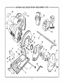
1
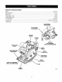
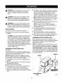
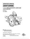
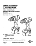
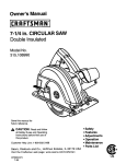
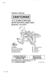
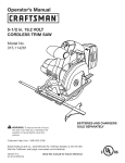
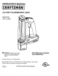
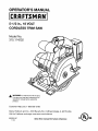
OPERATOR'S
MANUAL
II:RRFTSMRN°I
5-1/2 in., 18 VOLT
CORDLESS TRIM SAW
Model No.
315.114232
_
WARNING: To reduce the risk of injury,
the user must read and understand the
operator's manual before using this
product.
Customer
Help Line: 1-800-932-3188
Sears, Roebuck
and Co., 3333 Beverly
Rd., Hoffman
Estates,
IL 60179
Visit the Craftsman web page: www.sears.com/craftsman
983000-507
11-04
Save this manual
for future
reference
USA
• Warranty ..........................................................................................................................................................................
2
•
Introduction .....................................................................................................................................................................
2
•
General Safety Rules ....................................................................................................................................................
3-4
•
Specific Safety Rules ....................................................................................................................................................
4-5
•
Safety Rules for Charger .................................................................................................................................................
•
Symbols ........................................................................................................................................................................
•
Features ......................................................................................................................................................................
6
7-8
9-10
• Assembly ..................................................................................................................................................................
10-11
•
Operation ..................................................................................................................................................................
12-19
•
Maintenance ..................................................................................................................................................................
20
• Accessories ...................................................................................................................................................................
20
•
Exploded View and Parts List ...................................................................................................................................
•
Par_sOrdering/Service
....................................................................................................................................
FULL ONE YEAR WARRANTY
ON CRAFTSMAN
21-22
Back Page
TOOL
If this CRAFTSMAN tool fails to give complete satisfaction within one year from the date of purchase, RETURN IT TO
THE NEAREST SEARS STORE OR SEARS SERVICE CENTER IN THE UNITED STATES, and Sears will replace it, free
of charge.
If this CRAFTSMAN
of purchase.
tool is used for commercial or rental purposes, this warranty applies for only 90 days from the date
This warranty gives you specific legal rights, and you may also have other rights which vary from state to state.
Sears, Roebuck and Co., Dept. 817WA, Hoffman Estates, IL 60179
This tool has many features for making its use more pleasant and enjoyable. Safety, performance, and dependability
have been given top priority in the design of this product making it easy to maintain and operate.
_L
WARNING! READ AND UNDERSTAND ALL
INSTRUCTIONS. Failureto follow all instructions
listed below, may result in electric shock, fire and/or
serious personal injury.
SAVE THESE
WORK
AREA
Keep your work area clean and well lit. Cluttered
benches and dark areas invite accidents.
•
Do not operate power tools in explosive atmospheres, such as in the presence of flammable
liquids, gases, or dust. Power tools create sparks
which may ignite the dust or fumes.
Keep bystanders,
children, and visitors away while
operating a power tool. Distractions can cause you to
lose control.
ELECTRICALSAFETY
•
A battery operated tool with integral batteries or a
separate battery pack must be recharged only with
the specified charger for the battery. A charger that
may be suitable for one type of battery may create a
risk of fire when used with another battery.
•
Use battery operated tool only with specifically
designated battery pack. Use of any other batteries
may create a risk of fire.
•
Use battery
MODEL
315.114232
•
•
•
•
only with charger
Do not wear loose clothing or jewelry. Contain long
hair. Loose clothes, jewelry, or long hair can be drawn
into air vents.
•
Do not use on a ladder or unstable support. Stable
footing on a solid surface enables better control of the
tool in unexpected situations.
TOOLUSEAND
Use clamps
support the
the work by
may lead to
•
Do not force tool. Use the correct tool for your
application, The correct tool will do the job better and
safer at the rate for which it is designed.
Do not use tool if switch does not turn it on or off. A
tool that cannot be controlled with the switch is
dangerous and must be repaired.
Disconnect battery pack from tool or place the
switch in the locked or off position before making
any adjustments, changing accessories, or storing
the tool. Such preventive safety measures reduce the
risk of starting the tool accidentally.
Store idle tools out of reach of children and other
untrained persons. Tools are dangerous in the hands
of untrained users.
•
•
•
Do not abuse the cord. Never use the cord to carry
the charger. Keep cord away from heat, oil, sharp
edges, or moving parts. Replace damaged cords
immediately.
Damaged cords may create a fire.
•
SAFETY
Stay alert, watch what you are doing and use
common sense when operating a power tool. Do
not use tool while tired or under the influence of
drugs, alcohol, or medication. A moment of inattention while operating power tools may result in serious
personal injury.
Dress properly. Do not wear loose clothing
jewelry. Contain long hair. Keep your hair,
and gloves away from moving parts. Loose
jewelry, or long hair can be caught in moving
or
clothing,
clothes,
parts.
Avoid accidental starting. Be sure switch is in the
locked or off position before inserting battery pack.
Carrying tools with your finger on the switch or inserting the battery pack into a tool with the switch on
invites accidents.
Remove adjusting keys or wrenches before turning
the tool on. A wrench or a key that is left attached to a
rotating part of the tool may result in personal injury.
CARE
•
listed.
BATTERY PACK
Item no. 9 11378
(130139020)
Do not overreach. Keep proper footing and balance
at all times. Proper footing and balance enable better
control of the tool in unexpected situations.
Use safety equipment. Always wear eye protection.
Dust mask, non-skid safety shoes, hard hat, or hearing
protection must be used for appropriate conditions.
•
CHARGER
Item no. 9 11379
(1426101)
PERSONAL
•
•
INSTRUCTIONS
•
•
•
•
or other practical way to secure and
workpiece to a stable platform. Holding
hand or against your body is unstable and
loss of control.
When battery pack is not in use, keep it away from
other metal objects like: paper clips, coins, keys,
nails, screws, or other small metal objects that can
make a connection from one terminal to another.
Shorting the battery terminals together may cause
sparks, burns, or a fire.
Maintain tools with care. Keep cutting tools sharp
and clean. Properly maintained tools with sharp
cutting edges are less likely to bind and are easier to
control.
•
Check for misalignment
or binding of moving parts,
breakage of parts, and any other condition that
may affect the tool's operation. If damaged, have
the tool serviced before using. Many accidents are
caused by poorly maintained tools.
•
Use only accessories that are recommended
by the
manufacturer for your model. Accessories that may
be suitable for one tool may create a risk of injury when
used on another tool.
•
Keep the tool and its handle dry, clean and free
from oil and grease. Always use a clean cloth when
cleaning. Never use brake fluids, gasoline, petroleumbased products, or any strong solvents to clean the
tool. Following this rule will reduce the risk of loss of
control and deterioration
of the enclosure plastic.
SERVICE
• Tool service must be performed only by qualified
repair personnel. Service or maintenance performed
by unqualified personnel may result in a risk of injury.
• When servicing a tool, use only identical replacement parts. Follow instructions in the Maintenance
section of this manual. Use of unauthorizedparts or
failure to follow Maintenance Instructionsmay create a
risk of shock or injury.
•
DANGER! Keep hands away from cuffing area and
blade. Keep your second hand on auxiliary handle
or motor housing. If both hands are holdingthe saw,
they cannot be cut by the blade.
•
When ripping always use a rip fence or an edge
guide. This improves the accuracy of cut and reduces
the chance of blade binding.
•
•
Keep your body positioned to either side of the
saw blade, but not in line with the saw blade. KICKBACK could cause the saw to jump backwards.
Always use blades with correct size and shape
(diamond vs. round) arbor holes. Bladesthat do not
match the mounting hardware of the saw will run eccentrically,causing loss of control.
•
Do not reach underneath the work. The guard cannot protect you from the blade below the work.
•
•
Check the lower guard for proper closing before
each use. Do not operate saw if lower guard does
not move freely and close instantly. Never clamp or
tie the lower guard into the open position. If saw is
accidentally dropped, lower guard may be bent. Raise
the lower guard with the retracting handle and make
sure it moves freely and does not touch the blade or
any other part, in all angles and depths of cut.
Never use damaged or incorrect blade washers
or bolts. The blade washers and bolt were specially
designedfor the saw,for optimum performanceand
safety of operation.
•
Causes and Operator Prevention of Kickback:
•
•
•
Kickbackis a sudden reaction to a pinched, bound, or
misaligned saw blade, causing an uncontrolledsaw to
lift up and out of the workpiece toward the operator.
When the blade is pinched or bound tightly by the kerr
closing down, the blade stalls and the motor reaction
drives the unit rapidly back toward the operator.
Check the operation and condition of the lower
guard spring. If the guard and the spring are not
operating properly, they must be serviced before
use. Lower guard may operate sluggishlydue to damaged parts, gummy deposits, or a buildupof debris.
Lower guard should be retracted manually only
for special cuts such as "Pocket Cuts" and "Compound Cuts". Raise lower guard by Retracting
Handle. As soon as blade enters the material,
lower guard must be released. For all other sawing,
the lower guard should operate automatically.
If the blade becomes twisted or misalignedin the cut,
the teeth at the back edge of the blade can dig intothe
top surface of the wood causing the blade to climb out
of the kerf and jump back toward the operator.
Kickbackis a result of tool misuse and/or incorrectoperating procedures or conditionsand can be avoided
by taking proper precautionsas givenbelow:
Always observe that the lower guard is covering
the blade before placing saw down on bench or
floor. An unprotected, coasting blade will cause the
saw to walk backwards, cutting whatever is in its path.
Be aware of the time it takes for the blade to stop after
switch is released.
•
Maintain a firm grip on the saw and position your
body and arm in a way that allows you to resist
KICKBACK forces. KICKBACK forces can be controlled by the operator, if proper precautionsare taken.
•
When blade is binding, or when interrupting a
cut for any reason, release the trigger and hold
the saw motionless in the material until the blade
comes to a complete stop. Never attempt to remove the saw from the work or pull the saw backward while the blade is in motion or KICKBACK
may occur. Investigateand take correctiveactionsto
eliminate the cause of blade binding.
•
When restarting a saw in the workpiece, center the
saw blade in the kerf and check that teeth are not
engaged into the material. If saw blade is binding, it
may walk up or KICKBACK from the workpiece as the
saw is restarted.
NEVER hold piece being cut in your hands or
across your leg. It is importantto support the work
properly to minimize body exposure, blade binding, or
loss of control.
Hold tool by insulating gripping surfaces when
performing an operation where the cutting tool
may contact hidden wiring. Contact with a "live" wire
will also make exposed metal parts of the tool "live"
and shock the operator.
4
Additional Specific Safety Rules
•
Battery tools do not have to be plugged into an
electrical outlet; therefore, they are always in
operating condition. Be aware of possible hazards
when not using the battery tool or when changing
accessories. Following this rule will reduce the risk of
electric shock, fire, or serious personal injury.
• Do not place battery tools or their batteries near
fire or heat. This will reduce the risk of explosion and
possibly injury.
•
Support large panels to minimize the risk of blade
pinching and KICKBACK. Large panels tend to sag
under their own weight. Supports must be placed
under the panel on both sides, near the line of cut and
near the edge of the panel.
•
Do not use dull or damaged blade. Unsharpened
or improperly set blades produce narrow kerr causing
excessive friction, blade binding, and KICKBACK.
•
Blade depth and bevel adjusting locking levers
must be tight and secure before making cut. If
blade adjustment shifts while cutting, it will cause binding and KICKBACK.
•
•
Use extra caution when making a "Pocket Cut"
into existing walls or other blind areas, The protrudingblade may cut objectsthat can cause KICKBACK.
•
•
Hold tool by insulated gripping surfaces when
performing an operation where the cutting tool may
contact hidden wiring. Contact with a "live" wire will
also make exposed metal parts of the tool "live" and
shock the operator.
•
Know the power tool. Read operator's manual carefully. Learn its applications and limitations, as well
as the specific potential hazards related to this tool.
Following this rule will reduce the risk of electric shock,
fire, or serious injury.
• Always wear safety glasses with side shields.
Everyday glasses have only impact resistant lenses.
They are NOT safety glasses. Following this rule will
reduce the risk of eye injury.
•
Protect your lungs. Wear a face or dust mask if the
operation is dusty. Following this rule will reduce the
risk of serious personal injury.
•
Protect your hearing. Wear hearing protection during extended periods of operation. Following this rule
will reduce the risk of serious personal injury.
Never use a battery that has been dropped or
received a sharp blow. A damaged battery is subject
to explosion. Properly dispose of a dropped or damaged battery immediately.
Batteries vent hydrogen gas and can explode in
the presence of a source of ignition, such as a pilot
light. To reduce the risk of serious personal injury,
never use any cordless product in the presence of
open flame. An exploded battery can propel debris and
chemicals. If exposed, flush with water immediately.
• Do not charge battery tool in a damp or wet
location. Following this rule will reduce the risk of
electric shock.
•
For best results, the battery tool should be charged
in a location where the temperature
is more than
50°F but less than IO0°F. Do not store outside or in
vehicles.
Under extreme usage or temperature conditions, battery leakage may occur. If liquid comes
in contact with your skin, wash immediately with
soap and water, then neutralize with lemon juice
or vinegar. If liquid gets into your eyes, flush them
with clean water for at least 10 minutes, then seek
immediate medical attention. Following this rule will
reduce the risk of serious personal injury.
_k
could result in a risk of fire and electric shock. If
extension cord must be used, make sure:
WARNING! READ AND UNDERSTAND ALL
INSTRUCTIONS. Failureto follow all instructions
listed below, may resultin electric shock, fire
and/or serious personal injury.
a. That pins on plug of extension cord are the
same number, size and shape as those of
plug on charger.
• Before using battery charger, read all instructions
and cautionary markings in this manual, on battery
charger, battery, and product using battery to prevent
misuse of the products and possible injury or damage.
_i,
b. That extension cord is properly wired and in
good electrical condition; and
c. That wire size is large enough for AC ampere
rating of charger as specified below:
CAUTION: To reduce the risk of electric shock or
damage to the charger and battery, charge only
nickel-cadmium rechargeable batteries as specifically designated on the charger. Other types of
batteries may burst, causing personal injuryor
damage.
• Keep cord and charger from heat to prevent
damage to housing or internal parts.
• Do not let gasoline, oils, petroleum-based products,
etc. come in contact with plastic parts. They contain
chemicals that can damage, weaken, or destroy plastic.
• An extension cord should not be used unless
absolutely necessary. Use of improper extension cord
A
25'
50'
100'
Cord Size (AWG)
16
16
16
NOTE: AWG = American Wire Gauge
Do not operate charger with a damaged cord or
plug, which could cause shorting and electric shock. If
damaged, have the charger replaced by an authorized
serviceman.
• Do not use charger outdoors or expose to wet or
damp conditions. Water entering charger will increase
the risk of electric shock.
• Use of an attachment not recommended or sold
by the battery charger manufacturer may result in
a risk of fire, electric shock, or injury to persons,
Following this rule will reduce the risk of electric shock,
fire, or serious personal injury.
• Do not abuse cord or charger. Never use the cord to
carry the charger. Do not pull the charger cord rather
than the plug when disconnecting from receptacle.
Damage to the cord or charger could occur and create
an electric shock hazard. Replace damaged cords immediately.
• Make sure cord is located so that it will not be
stepped on, tripped over, come in contact with
sharp edges or moving parts or otherwise subjected to damage or stress. This will reduce the risk of
accidental falls, which could cause injury, and damage
to the cord, which could result in electric shock.
Cord Length (Feet)
Do not operate charger if it has received a sharp
blow, been dropped, or otherwise damaged in any
way. Take it to an authorized servicemanfor electrical
check to determine if the charger is in good working
order.
Do not disassemble charger. Take it to an authorized
serviceman when service or repair is required. Incorrect reassembly may result in a risk of electric shock or
fire.
•
Unplug charger from outlet before attempting any
maintenance or cleaning to reduce the risk of
electric shock,
•
Disconnect charger from the power supply when
not in use. This will reduce the risk of electric shock
•
or damage to the charger if metal items should fall into
the opening. It also will help prevent damage to the
charger during a power surge.
Risk of electric shock. Do not touch uninsulated
portion of output connector
terminal.
or uninsulated
battery
Save these instructions. Refer to them frequently and
use them to instruct others who may use this tool. If
you loan someone this tool, loan them these instructions also to prevent misuse of the product and
possible injury.
WARNING: Some dust created by power sanding, sawing, grinding, drilling, and other construction activities
contains chemicals known to cause cancer, birth defects or other reproductive harm. Some examples of these
chemicals are:
• lead from lead-based paints,
• crystalline silica from bricks and cement and other masonry products, and
• arsenic and chromium from chemically-treated lumber.
Your risk from these exposures varies, depending on how often you do this type of work. To reduce your exposure
to these chemicals: work in a well ventilated area, and work with approved safety equipment, such as those dust
masks that are specially designed to filter out microscopic particles.
Some of the following symbols may be used on this tool. Please study them and learn their meaning.
interpretation
of these symbols will allow you to operate the tool better and safer.
SYMBOL
NAME
DESIGNATION/EXPLANATION
V
Volts
Voltage
A
Amperes
Current
Hz
Hertz
Frequency
W
Watt
Power
Minutes
Time
min
Alternating
Current
(cycles
per second)
Type of current
Direct Current
Type or a characteristic
no
No Load Speed
Rotational
[]
Class II Construction
Double-insulated
.../min
Per Minute
Revolutions,
@
Wet Conditions
Alert
Read The Operator's
Q
A
Manual
of current
speed, at no load
construction
strokes,
Do not expose
surface
speed, orbits
etc., per minute
to rain or use in damp locations.
To reduce the risk of injury, user must read and understand
operator's manual before using this product.
Eye Protection
Always
shields
Safety
Precautions
Alert
Proper
wear safety goggles or safety glasses with side
and a full face shield when operating this product.
that involve
your safety.
No Hands Symbol
Failure to keep your hands away from the blade will result in
serious personal injury.
No Hands Symbol
Failure to keep your hands away from the blade will result in
serious personal injury.
No Hands Symbol
Failure to keep your hands away from the blade will result in
serious personal injury.
,_
No Hands Symbol
Failure to keep your hands away from the blade will result in
serious personal injury.
(_)
Hot Surface
To reduce the risk of injury or damage,
any hot surface.
_)
7
avoid contact
with
Thefollowing
signalwordsandmeanings
areintended
toexplain
thelevelsofriskassociated
withthisproduct.
SYMBOL
SIGNAL
MEANING
,_
DANGER:
Indicates an imminently hazardous situation, which, if not avoided, will
result in death or serious injury.
_i,
WARNING:
Indicates a potentially hazardous situation, which, if not avoided, could
result in death or serious injury.
,_,
CAUTION:
Indicates a potentially hazardous situation, which, if not avoided, may
result in minor or moderate injury.
CAUTION:
(Without Safety Alert Symbol) Indicates a situation that may result in
property damage.
SERVICE
Servicing requires extreme care and knowledge and
should be performed only by a qualified service technician. For service we suggest you return the product to
your nearest AUTHORIZED SERVICE CENTER for
repair. When servicing, use only identical replacement
parts.
_,
_1, WARNING: To avoid serious personal injury,
do not attempt to use this product until you read
thoroughly and understand completely the
operator's manual. Save this operator's manual
and review frequently for continuing safe operation and instructingothers who may use this
product.
WARNING:
0
The operation of any power tool can result in foreign objects being thrown into your eyes, which
can result in severe eye damage. Before beginning power tool operation, always wear safety
goggles or safety glasses with side shields and a full face shield when needed. We
recommend Wide Vision Safety Mask for use over eyeglasses or standard safety glasses with side
shields. Always use eye protection which is marked to comply with ANSI Z87.1.
SAVE THESE INSTRUCTIONS
8
PRODUCT
SPECIFICATIONS
Motor ......................................................................................................................................................................
Blade Diameter ..........................................................................................................................................................
Blade Arbor....................................................................................................................................................................
18 Volt DC
5-1/2 in,
3/8 in.
Cutting Depth at 900 .................................................................................................................................................
1-9/16 in.
Cutting Depth at 45° ...................................................................................................................................................
1-1/8 in.
No Load Speed ......................................................................................................................................................
4,500/min.
Charger Input .......................................................................................................................................
120 V, 60 Hz, AC only
Charge Rate ............................................................................................................................................................
3-6 Hours
BLADE WRENCH
STORAGEAREA
BLADEWRENCH
(5 mmHEXKEY)
LOCK-OFF
BUTTON
BATTERY
PACK
DEPTH OF
CUTADJUSTMENT
(DEPTH ADJUSTMENTKNOB)
SPINDLE LOCK
BUTTON
SWITCH
TRIGGER
EDGEGUIDESCREW
(WINGSCREW)
UPPER
LOWER BLADE
GUARDHANDLE
LOWER
BLADEGUARD
BEVELCUTADJUSTMENT
(BEVELADJUSTMENT
KNOB)
BASE
ASSEMBLY
BLADE
Fig. 1
KNOW THE TRIM
See Figure 1.
SAW
SPINDLE LOCK BUTI'ON
Depressing the spindle lock button will allow you to install
or replace the saw blade without the spindle turning. Press
the spindle lock button and use the blade wrench to tighten
or loosen the blade screw.
Before attempting to use this product, familiarizeyourself
with all operating features and safety rules.
SWITCH
LOWER BLADE GUARD
The saw is equipped with a lock-off button which reduces
the possibility of accidental starting. The lock-off button
is located on the handle above the switch trigger.You
must depress the lock-off button in order to pull the switch
trigger. The lock resets each time the trigger is released.
The lower blade guard will protect the saw blade when the
saw is not in use. It will rotate out of the way when making
a cut.
LOWER BLADE GUARD HANDLE
NOTE: You can depress the lock-off button from either the
left or right side.
The lower blade guard has a handle attached to it allowing
you to rotate the lower blade guard out of the way to install
or replace the saw blade, it is also used when making a
pocket cut to expose the saw blade.
UNPACKING
_k
This product requires assembly.
• Carefully remove the tool and any accessories from the
box. Make sure that all items listed in the packing list
are included.
d_lL WARNING: Do not attempt to modify this tool
or create accessories not recommended for use
with this tool. Any such alteration or modification is
misuse and could result in a hazardous condition
leading to possible serious personal injury.
• Inspect the tool carefully to make sure no breakage or
damage occurred during shipping.
• Do not discard the packing material until you have
carefully inspected and satisfactorily operated the tool.
• If any parts are damaged or missing, please call
1-800-932-3188 for assistance.
PACKING
WARNING: If any parts are missing do not operate
this tool until the missing parts are replaced. Failure
to do so could result in possible serious personal
injury.
_lb
LIST
Cordless Trim Saw
Battery Pack
Charger
Blade
Blade Wrench
Case
Operator's Manual
10
WARNING: To prevent accidental starting that
could cause serious personal injury, always remove
the battery pack from the tool when assembling
parts.
SPINDLE
LOCKBUTTON
NOTE: The saw is assembled with the battery pack
attached.
LOWERBLADE
GUARDHANDLE
TO REMOVE BATTERY PACK
See Figure 2.
•
Locate latches on side of battery pack and depress to
release battery pack from the saw.
•
Remove battery pack from the saw.
TO ASSEMBLE
OR REMOVE
TO ASSEMBLE
See Figure 3.
BLADE:
_k
BLADE
WARNING: A 5-1/2 in. blade is the maximum blade
capacity of the saw. Never use a blade that is too
thick to allow outer blade washer to engage with
the flats on the spindle. Larger blades will come in
contact with the blade guard, while thicker blades will
prevent blade screw from securing blade on spindle.
Either of these situations could result in a serious
accident,
DEPRESSLATCHESTO
RELEASEBATTERYPACK
TO
INNER
BLADEWASHER
OUTER
BLADE WASHER
BLADESCREW
Fig. 3
•
Fit saw blade inside lower blade guard and onto
spindle.
NOTE: The saw teeth point upward at the front of saw
as shown in figure 3.
TO
INSTALL
•
Depress spindle lock button, then replace blade screw.
Tighten blade screw securely.
• Return blade wrench to storage area.
REMEMBER: Never use a blade that is too thick to allow
the outer blade washer to engage with the flats on the
spindle.
Fig. 2
•
•
Remove battery pack from saw.
Locate latches on side of battery pack and depress to
release battery pack from the saw.
•
Remove blade wrench (5 mm hex key) from storage
area.
•
Depress spindle lock button and remove blade screw
and outer blade washer.
NOTE: Turn blade screw clockwise to remove.
_k
Replace outer blade washer.
NOTE: Turn blade screw counterclockwise to tighten,
LATCHES
BATrERY PACK
•
•
Wipe a drop of oil onto inner blade washer and outer
blade washer where they contact blade.
WARNING: If inner blade washer has been removed, replace it before placing blade on spindle.
Failure to do so could cause an accident since blade
will not tighten properly.
11
_
WARNING: Do not allow familiarity with tools to
make you careless. Remember that a careless
fraction of a second is sufficient to inflict serious
injury.
_
WARNING: Always wear safety goggles or safety
glasses with side shields when operating tools.
Failure to do so could result in objects being thrown
into your eyes, resulting in possible serious injury.
• The charge indicator light (LED), located on the charging stand, will light up red and glow when the charger
is properly connected to power supply. This light
indicates the charger is operating properly. It will
remain on until battery pack is removed from charging
stand or charger is disconnected from power supply.
NOTE: If charger does not charge battery pack, return
battery pack and charging assembly to your nearest
Sears Repair Center for electrical check.
• After normal usage, 3 hours or less of charging time is
required to fully recharge battery pack.
_i
WARNING: Do not use any attachments or accessories not recommended by the manufacturer of
this tool. The use of attachments or accessories not
recommended can result in serious personal injury.
NOTE: If battery pack is completely discharged,
6 hours or longer of charging time is required to fully
recharge battery pack.
• The battery pack will become slightly warm to the
touch while charging. This is normal and does not
indicate a problem.
APPLICATIONS
You may use this tool for the following purposes:
•
• Cutting all types of wood products (lumber, plywood,
paneling)
• When batteries become fully charged, unplug charger
from power supply and remove the battery pack.
CAUTION: To prevent damage to the battery pack,
remove the battery pack from the charger immediately if no LED comes on. Return the battery pack
and charger to your nearest service center for checking or replacing. Also, if you are removing the battery
pack from the charger and no LEDs are on, return
both the battery pack and the charger to your nearest service center. Do not insert another battery pack
into the charger. A damaged charger may
damage a battery pack.
CHARGING
THE BATTERY
Do not place charger in an area of extreme heat or
cold. It will work best at normal room temperature.
CHARGING
A HOT BATTERY
PACK
When using the tool continuously, the batteries in the
battery pack will become hot. You should let a hot battery
pack cool down for approximately 30 minutes before
attempting to recharge.
NOTE: This situation only occurs when continuous use of
the tool causes the batteries to become hot. It does not
occur under normal circumstances. Refer to "CHARGING
THE BATTERY PACK" for normal recharging of batteries.
If the charging assembly does not charge the battery pack
under normal circumstances, return both the battery pack
and charging assembly to your nearest Sears Repair Center for electrical check.
PACK
See Figure 4.
The battery pack for this tool has been shipped in a low
charge condition to prevent possible problems. Therefore,
you should charge overnight prior to use.
ADAPTER
BATTERY
NOTE: Batteries will not reach full charge the first time
they are charged. Allow several cycles (operation followed
by recharging) for them to become fully charged.
\
• Charge battery pack only with the charging assembly
provided.
• Make sure power supply is normal household voltage,
120 volts, 60 Hz, AC only.
• Connect charger to power supply.
• Place battery pack in charging stand. Align raised rib
on battery pack with groove in charging stand.
• Press down on battery pack to be sure contacts on
battery pack engage properly with contacts in charging
stand.
CHARGEINDICATOR
LIGHT
12
Fig. 4
TO INSTALL
BATTERY
PACK
DEPRESSSPINDLE
LOCK BuI"rON
See Figure 5.
NOTE: Battery pack is shipped in a low charge condition.
Therefore, it must be charged prior to use. Refer to page
12, "Charging Battery Pack" for charging instructions.
•
•
Place battery pack in the saw. Align raised rib on
battery pack with groove inside saw, then slide battery
pack in saw as shown in figure 4.
TO
LOOSEN
Make sure the latches on each side of the battery pack
snap into place and battery pack is secured in saw
before beginning operation.
BLADE
SCREW
\
TO
TIGHTEN
Fig. 6
BLADE GUARD SYSTEM
See Figure 7.
The lower blade guard attached to the trim saw is there
for your protection and safety. It should never be altered
for any reason. If it becomes damaged or begins to return
slow or sluggish, do not operate the saw until the damage
has been repaired or replaced. Always leave guard in
operating position when using saw.
LATCHES
BATrERYPACK
Fig. 5
,_
,_
CAUTION: When placing battery pack in the saw,
be sure raised rib on battery pack aligns with groove
inside saw and latches snap into place properly.
Improper assembly can cause damage to saw and
battery pack.
TO REMOVE
See Figure 6.
Remove battery pack from saw.
•
Remove blade wrench from storage area.
•
Position saw as shown in figure 6, depress spindle lock
button, and remove blade screw.
NOTE: Turn blade screw clockwise to remove.
•
Remove outer blade washer.
LOWER BLADEGUARD
IS IN UP POSITION
WHEN MAKINGA CUT
NOTE: Blade can be removed at this point.
,_k
DANGER: When sawing through workpiece, lower
blade guard does not cover blade on the underside
of workpiece. Since blade is exposed on undersideof
workpiece, keep hands and fingers away from cutting
area. Any part of your body coming in contact with
moving blade will result in serious injury.
Never use saw when guard is not operating correctly.
Guard should be checked for correct operation before each
use. if you drop the saw, check the lower blade guard and
bumper for damage at all depth settings before reuse.
NOTE: The guard is operating correctly when it moves
freely and readily returns to the closed position. If for any
reason the lower blade guard does not close freely, take
it to the nearest Sears Service Center for service before
using.
BLADE
•
BLADE
WRENCH
WARNING: Battery tools are always in operating
condition. Therefore, switch should always be locked
when not in use or carrying at your side.
BLADE EXPOSEDON
UNDERSIDE OF WORKPIECE
13
Fig. 7
KICKBACK
TO LESSEN THE CHANCE
See Figure 1I.
See Figures 8 - 11.
OF KICKBACK:
• Always keep the correct blade depth setting - the
correct blade depth setting for all cuts should not
exceed 1/4 in. below the material to be cut. One blade
tooth below the material to be cut works best for most
efficient cutting action.
BLADESETTOODEEP
Fig. 8
The best guard against kickback is to avoid dangerous
practices.
Kickback occurs when the blade stalls rapidly and the saw
is driven back towards you. Blade stalling is caused by any
action which pinches the blade in the wood.
,_
DANGER: Release switch immediately if blade binds
or saw stalls. Kickback could cause you to lose control
of the saw. Loss of control can lead to serious injury.
CORRECTBLADEDEPTHSE'mNG=
BLADEEXPOSEDONEBLADETOOTH
BELOWTHEMATERIALTOBECUT
Fig. 10
KICKBACK
IS CAUSED
BY:
•
Incorrect blade depth setting.
•
Sawing into knots or nails in workpiece.
•
Twisting blade while making a cut.
•
Making a cut with a dull, gummed up, or improperly set
blade.
•
•
•
Inspect the workpiece for knots or nails before
beginning a cut. Never saw into a knot or nail.
•
Make straight cuts. Always use a straight edge guide
when rip cutting. This helps prevent twisting the blade in
the cut.
Always use clean, sharp and properly set blades. Never
make cuts with dull blades.
Incorrectly supporting workpiece.
Forcing a cut.
To avoid pinching the blade, support the workpiece
properly before beginning a cut. The right and wrong
ways to support large pieces of work are shown in
figures 9 and 11.
Fig. 9
•
Cutting warped or wet lumber.
• Tool misuse or incorrect operating procedures.
RIGHT
14
Fig. 11
• Whenmakinga cutusesteady,
evenpressure.
Neverforcecuts.
• Donotcutwarpedorwetlumber.
• Alwaysholdthesawfirmlywithbothhandsandkeep
yourbodyina balanced
position
soastoresistthe
forcesofkickback
shoulditoccur.
STARTING
A CUT
See Figure 13.
Know the right way to use the saw.
Never use the saw as shown in figure 14.
Never place your hand on the workpiece behind the
saw while making a cut.
When using the saw, always stay alert and exercise
control. Do not remove the saw from workpiece while
the blade is moving.
DEPTH
OF CUT ADJUSTMENT
Always keep correct blade depth setting. The correct blade
depth setting for all cuts should not exceed 1/4 inch below
the material to be cut. More blade depth will increase the
chance of kickback and cause the cut to be rough, One
blade tooth below the material to be cut works best for
most efficient cutting action.
TO ADJUST
See Figurel_
BLADE
\
DEPTH
•
•
Remove battery pack from saw,
Loosen depth adjustment knob.
•
Hold base flat against the workpiece and raise or lower
saw until the required depth is reached.
•
Tighten depth adjustment knob securely.
Fig. 13
_
TO RAISE
SAW
WARNING: To make sawing easier and safer,
always maintain proper control of the saw. Loss of
control of the saw could cause an accident resulting
in possible serious injury.
BASE
ASSEMBLY
TO
LOWERSAW
TO
LOOSEN
TIGHTEN
DEPTH
ADJUSTMENT
KNOB
Fig. 12
WRONG
15
Fig. 14
TO HELP MAINTAIN
CONTROL
Depress the lock-off button and squeeze the switch trigger
to start the saw. Always let the blade reach full speed,
then guide the saw into the workpiece.
See Figures 15 - 16.
•
Always support the workpiece near the cut,
•
Support the workpiece so the cut will be on your left.
•
Clamp the workpiece so it will not move during the cut.
Place the workpiece with its good side down.
NOTE: The good side is the side on which appearance is
important.
\
Before beginning a cut, draw a guideline along the desired
line of cut.Then place front edge of base on that part of
the workpiece that is solidly supported.
Never place the saw on that part of the workpiece that
will fall off when the cut is made.
Hold the saw firmly with both hands.
RIGHT
_i
Fig. 16
WARNING: The blade coming in contact with the
workpiece before it reaches full speed could cause
the saw to "kickback" towards you resulting in serious
injury.
When making a cut use steady, even pressure. Forcing
causes rough cuts, could shorten the life of the saw and
could cause "kickback,"
WRONG
REMEMBER: When sawing through work, the lower
blade guard does not cover the blade, exposing it on the
underside of work, Keep the hands and fingers away from
cutting area. Any part of your body coming in contact with
the moving blade will result in serious injury.
After you complete the cut release the trigger and allow
the blade to come to a complete stop. Do not remove the
saw from workpiece while the blade is moving.
Fig. 15
,_i
16
CAUTION: When lifting the saw from the workpiece,
the blade is exposed on the underside of the saw until
the lower blade guard closes. Make sure lower blade
guard is closed before setting the saw down on work
surface.
TO CROSS
CUT OR RIP CUT
A width of cut scale has been provided on the base of the
saw. When making straight cross cuts or rip cuts, the scale
can be used to measure up to four inches to the right side
of the blade. It can be used to measure up to one inch to
the left side of the blade.
See Figure 17.
When making a cross cut or rip cut, align the line of cut
with the outer blade guide notch on the saw base.
TOP VIEW OF SAW
EDGE GUIDE
See Figure 19.
GUIDELINE
BLADE
GUIDE NOTCH
Use the optional edge guide with the saw when making
wide rip cuts. A five inch scale has been provided on the
edge guide. When using the width of cut scale on the base
in combination with the edge guide, cuts can be made up
to 6 in. to the left of the edge guide or 8-7/8 in. to the right
of the edge guide.
The edge guide helps prevent the blade from twisting in a
cut. The blade twisting in a cut can cause kickback.
-.FRO" TT
i
OFSAW
,I
TO ASSEMBLE
'd!
EDGE GUIDE
See Figure 19.
•
Remove battery pack from saw.
ALIGN OUTER BLADE GUIDENOTCHON SAW BASEWITH LINE OF
CUT AS SHOWN WHEN MAKINGCROSS CUTS OR RIP CUTS
Fig. 17
Since blade thicknessesvary, always make a trial cut in
scrap material along a guideline to determine how much,
if any, the guideline must be offset to produce an accurate
cut.
NOTE: The distance from the line of cut to the guideline is
the amount you should offset the guideline.
WIDTH OF CUT SCALE
See Figure 18.
G°'DE
BASE
ASSEMBLY
Fig. 19
•
Place edge guide through holes in saw base.
• Adjust edge guide to the width needed.
• Tighten edge guide screw (wing screw) securely.
WIDTH OF
CUT SCALE
When using an edge guide, position the face of the edge
guide firmly against the edge of workpiece. This makes for
a true cut without pinching the blade. The guiding edge of
workpiece must be straight for the cut to be straight. Use
caution to prevent the blade from binding in the cut.
BLADE
Fig. 18
17
ALTERNATIVE
See Figure20.
RIP METHOD
Align the line of cut with the inner blade guide notch on
the saw base when making 45 ° bevel cuts.
Since blade thicknesses
vary and different angles
require different settings, always make a trial cut in
scrap material along a guideline to determine
how
much you should offset the guideline on the board to
be oat.
Using C-clamps, firmly clamp a straight edge to the
workpeice and guide the saw along the straight edge to
achieve a straight rip cut. Do not bind the blade in the cut.
WORKPIECE
When making a bevel cut hold the saw firmly with both
hands as shown in figure 22.
STRAIGHT
EDGE
\
C-CLAMPBOTHENDSOF
STRAIGHTEDGEBEFORE
MAKINGCUT
Fig. 20
ALTERNATIVE
METHODFORRIP cu'n'ING
LOWER
BLADEGUARD Fig. 22
TO BEVEL CUT
See Figures 21 - 22.
Rest the front edge of the base on the workpiece. Depress
the lock-off button and squeeze the switch trigger to start
the saw. Always let the blade reach full speed, then guide
the saw into the workpiece.
The angle of cut of the saw may be adjusted to any
desired setting between zero and 50 °.
NOTE=When making cuts at 50 °, blade should be set at
full depth of cut.
WARNING: The blade coming in contact with the
workpiece before it reaches full speed could cause
saw to "kickback" toward you resulting in serious
injury.
When making 45 ° bevel cuts, there is a notch in the saw
base to help you line up the blade with the line of cut.
I
BEVEL
ADJUSTMENT
KNOB
After you complete the cut release the trigger and allow
the blade to come to a complete stop, After the blade has
stopped, lift the saw from the workpiece.
II I II.
TO ADJUST BEVEL SETTING
See Figure 21.
BEVEL_/""'"_
J_P"hl_, _'_
///J
,?,d, ,ll'll_//,, _
•
Remove battery pack from saw.
•
Loosen bevel adjustment knob.
•
Raise motor housing end of saw until you reach
desired angle setting on bevel scale.
• Tighten bevel adjustment knob securely.
l; ,rGU'DEL'NE:
?:,F
,_
[ I1_ /V_/ I t7 _',_,'J
/,'; /vvlr/vh
ALIGNINNERBLADEGUIDENOTCHONSAWBASEWITH
LINEOFCUTASSHOWNWHENMAKING45° BEVELCUTS
Fig. 21
18
WARNING:
Attempting bevel cut without knob
securely tightened can result in serious injury.
POSITIVE 0 ° BEVEL STOP
See Figure 23.
ADJUSTMENT
SCREW
TO POCKET CUT
See Figure 24.
,_
BEVEL
ADJUSTMENT
KNOB
WARNING" Always adjust bevel setting to zero
before making a pocket cut. Attempting a pocket cut
at any other setting can result in loss of control of the
saw possibly causing serious injury.
Adjust the bevel setting to zero, set blade to correct blade
depth setting, and swing the lower blade guard up using
the lower blade guard handle.
HEX NUT
Always raise the lower blade guard with the handle to
avoid serious injury.
BLADE
While holding lower blade guard by the handle, firmly rest
the front of the base flat against the workpiece with the
rear of the handle raised so the blade does not touch the
workpiece.
POSITIVE0°
BEVELSTOP
LOWERBLADE
GUARDHANDLE
COMBINATION
SQUARE
Fig. 23
The saw has a positive O° bevel stop that has been
factory adjusted to assure 0° angle of the saw blade when
making 90 ° cuts. However, misalignment can occur during
shipping.
POCKETCUT
TO CHECK
•
Remove battery pack from saw.
•
Place the saw in an upside down position on
workbench.
•
Using a combination square, check squareness of saw
blade to the base of the saw.
Remove battery pack from saw.
•
Loosen bevel adjustment knob.
•
Loosen hex nut securing adjustment screw.
After you complete the cut, release the trigger and allow
the blade to come to a complete stop. After the blade has
stopped, remove it from the workpiece. Corners may then
be cleared out with a hand saw or sabre saw.
• Turn screw and adjust base until square with saw blade.
,_
• Tighten hex nut and bevel adjustment knob securely.
,_,
Fig. 24
Depress the lock-off button and squeeze the switch trigger
to start the saw. Always let the blade reach full speed
then slowly lower blade into the workpiece until base
is flat against workpiece.
TO ADJUST
•
LOWERBLADE
GUARD
WARNING: Attempting to make cuts without bevel
adjustment knob securely tightened can result in
serious injury.
19
WARNING: Never tie the lower blade guard in a
raised position.Leaving the blade exposed could lead
to serious injury.
,_
WARNING: When servicing, use only identical
Craftsman replacement parts. Use of any other part
may create a hazard or cause product damage.
_
WARNING:
Always wear safety goggles or safety
glasses with side shields when using compressed air
to clean tools. If the operation is dusty, also wear a
dust mask.
_IL
_k
WARNING: Do not at any time let brake fluids,
gasoline, petroleum-based products, penetrating
oils, etc. come in contact with plastic parts. Chemicals can damage, weaken or destroy plastic which
may result in serious personal injury.
Only the parts shown on the parts list are intended to be
repaired or replaced by the customer. All other parts
should be replaced at a Sears Service Center.
WARNING: To avoid serious personal injury, always
remove the battery pack from the tool when cleaning
or performing any maintenance.
GENERAL
MAINTENANCE
Avoid using solvents when cleaning plastic parts. Most
plastics are susceptible to damage from various types of
commercial solvents and may be damaged by their use.
Use clean cloths to remove dirt, dust, oil, grease, etc.
BATTERIES
BATTERY
The battery pack for this tool is equipped with nickel-cadmium rechargeable batteries. Length of service from each
charging will depend on the type of work you are doing.
PREPARATION
PACK REMOVAL
To preserve natural resources, please
recycle or dispose of batteries
properly.
The batteries in this tool have been designed to provide
maximum trouble-free life. However, like all batteries, they
will eventually wear out. Do not disassemble battery pack
and attempt to replace the batteries. Handling of these
batteries, especially when wearing rings and jewelry, could
result in a serious burn.
This product contains nickel-cadmium
batteries. Local, state or federal
laws may prohibit disposal of nickelcadmium batteries in ordinary trash.
Consult your local waste authority for information
regarding available recycling and/or disposal options.
To obtain the longest possible battery life, we suggest the
following:
•
Remove the battery pack from the charger once it is
fully charged and ready for use.
For battery pack storage longer than 30 days:
,_k
• Store the battery pack where the temperature is below
80°F.
• Store battery packs in a "discharged" condition.
WARNING: Upon removal, cover the battery pack's
terminals with heavy-duty adhesive tape. Do not
attempt to destroy or disassemble battery pack or
remove any of its components. Nickel-cadmium
batteries must be recycled or disposed of properly.
Also, never touch both terminals with metal objects
and/or body parts as short circuit may result. Keep
away from children. Failure to comply with these
warnings could result in fire and/or serious injury.
The following recommended accessories are currently available at Sears Retail Stores.
• 5-1/2 in.Thin Kerf Blade
•
_k
Edge Guide
WARNING:
AND
FOR RECYCLING
The use of attachments or accessories not listed might be hazardous.
20
CRAFTSMAN
18 VOLT CORDLESS
TRIM
SAW - MODEL
NUMBER
315.114232
29
I
L
28
11
12
15
6
27
16
17
13
14
18
21
19
20
30
22
5
2
23
4
32
3
21
CRAFTSMAN
18 VOLT CORDLESS
TRIM
SAW - MODEL
NUMBER
315.114232
I
The model number will be found on a plate attached to the motor housing. Always mention the model number in all correspondence regarding your
CORDLESS TRIM SAW or when ordering repair parts.
SEE BACK
PAGE FOR PARTS
ORDERING
]
INSTRUCTIONS
PARTS LIST
Key
No.
Pa_
Number
Description
Key
No.
Quan.
Part
Number
Description
Quan.
1
6614301
Carriage Bolt (M6 x 100 mm) ....................... 1
18
6850303
Bearing Retainer .......................................... 1
2
670956015
Base Assembly ............................................ 1
19
6620104
* Screw (M2.6 x 10 mm Pan Hd.)................... 4
3
6614501
* Screw (M6 x 16 mm) .................................... 1
20
6112004
Inner Blade Washer ..................................... 1
4
5224502
Knob ............................................................ 2
21
***
Saw Blade ................................................... 1
5
6800101
Spring .......................................................... 1
22
6112101
Outer Blade Washer .................................... 1
6
520177001
6614401
Blade Screw ................................................ 1
6797401
Wing Screw ................................................. 1
Lock Nut ...................................................... 2
23
7
24
**Item
No.£
8
6802201
Hex Nut ........................................................ 1
25
**Item
No.911378
9
6621204
* Screw (M4 x 16 mm Pan Hd.) ...................... 1
26
6800201
Blade Wrench (5 mm Hex Key).................... 1
10
6614201
* Carriage Bolt (M6 x 13 mm) ......................... 1
27
670957001
Edge Guide (Not Included) .......................... 1
11
640556013
Upper Blade Guard ..................................... 1
28
9427205
Logo Plate ................................................... 1
12
6620803
* Screw (M4 x 22 mm Pan Hd.) ...................... 4
29
940271024
Data Plate .................................................... 1
13
5217802
Bumper ........................................................ 1
30
680027001
Washer ......................................................... 1
14
6619302
Bumper Screw (M5 x 15.5 ram)................... 1
31
9429817
Warning Label .............................................. 1
15
6867201
Torsion Spring .............................................. 1
32
5228001
Washer ......................................................... 2
16
550994007
Lower Blade Guard ...................................... 1
3009102145
Combo Case (Not Shown)
17
6807001
Ball Bearing (NTN #6000ZZ) ........................ 1
983000507
Operator's Manual (Not Shown)
* Standard
Hardware
** Can Be Purchased
*** Complete
Assortment
Item -- May Be Purchased
11379
Charger (1426101) ....................................... 1
Battery Pack (130139020) ........................... 1
Locally
Thru RSOS (Retail Special Order System)
Available At Your Nearest Sears Retail Store
22