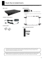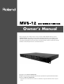
1
Owner’s Manual
Before using this unit, carefully read the sections entitled: “USING THE UNIT SAFELY”(p. 4) and
“IMPORTANT NOTES” (p. 6). These sections provide important information concerning the proper
operation of the unit. Additionally, in order to feel assured that you have gained a good grasp of
every feature provided by your new unit, owner’s manual should be read in its entirety. The manual
should be saved and kept on hand as a convenient reference.
Copyright © 2010 ROLAND CORPORATION
All rights reserved. No part of this publication may be reproduced in any form without the written
permission of ROLAND CORPORATION.
*
All product names mentioned in this document are trademarks or registered trademarks of their respective
owners.
About the lwIP
This product uses the lwIP for TCP/IP stack of LAN. Be aware of the lwIP copyright here below.
Copyright (c) 2001, 2002 Swedish Institute of Computer Science. All rights reserved.
Redistribution and use in source and binary forms, with or without modification, are permitted provided that the following conditions are met:
1. Redistributions of source code must retain the above copyright notice, this list of conditions and the following disclaimer.
2. Redistributions in binary form must reproduce the above copyright notice, this list of conditions and the following disclaimer in the
documentation and/or other materials provided with the distribution.
3. The name of the author may not be used to endorse or promote products derived from this software without specific prior written permission.
THIS SOFTWARE IS PROVIDED BY THE AUTHOR ``AS IS'' AND ANY EXPRESS OR IMPLIED WARRANTIES, INCLUDING, BUT NOT LIMITED TO, THE IMPLIED
WARRANTIES OF MERCHANTABILITY AND FITNESS FOR A PARTICULAR PURPOSE ARE DISCLAIMED. IN NO EVENT SHALL THE AUTHOR BE LIABLE FOR
ANY DIRECT, INDIRECT, INCIDENTAL, SPECIAL, EXEMPLARY, OR CONSEQUENTIAL DAMAGES (INCLUDING, BUT NOT LIMITED TO, PROCUREMENT OF
SUBSTITUTE GOODS OR SERVICES; LOSS OF USE, DATA, OR PROFITS; OR BUSINESS INTERRUPTION) HOWEVER CAUSED AND ON ANY THEORY OF
LIABILITY, WHETHER IN CONTRACT, STRICT LIABILITY, OR TORT (INCLUDING NEGLIGENCE OR OTHERWISE) ARISING IN ANY WAY OUT OF THE USE OF
THIS SOFTWARE, EVEN IF ADVISED OF THE POSSIBILITY OF SUCH DAMAGE.
Check the included items
The following items are included. Please make sure that all items are present. If anything is missing, please contact your dealer.
MVS-12 itself
Rubber Foot (four)
fig.MVS-12-itself.eps
fig.rubber-feet.eps
Attach the included rubber feet as needed. Refer the figure
below to attach.
* The rubber feet are arraged onto one pad. Remove from the pad to
use them.
fig.rubber-foot-location.eps
AC Adaptor and Power Cord
fig.PSB1U.eps
Ferrite Core (two)
fig.ferrite-core.eps
Owner’s Manual (this document)
fig.owners-manual.eps
The explanations in this manual include illustrations that depict what should typically be shown by the display. Note,
however, that your unit may incorporate a newer, enhanced version of the system, so what you actually see in the
display may not always match what appears in the manual.
MMP (Moore Microprocessor Portfolio) refers to a patent portfolio concerned with microprocessor architecture, which
was developed by Technology Properties Limited (TPL). Roland has licensed this technology from the TPL Group.
3
USING THE UNIT SAFELY
The
symbol alerts the user to important instructions
or warnings.The specific meaning of the symbol is
determined by the design contained within the
triangle. In the case of the symbol at left, it is used for
Used for instructions intended to alert
the user to the risk of death or severe
injury should the unit be used
improperly.
Used for instructions intended to alert
the user to the risk of injury or material
damage should the unit be used
improperly.
* Material damage refers
other adverse effects
respect to the home
furnishings, as well
animals or pets.
The
symbol alerts the user to items that must never
be carried out (are forbidden). The specific thing that
must not be done is indicated by the design contained
within the circle. In the case of the symbol at left, it
means that the unit must never be disassembled.
to damage or
caused with
and all its
to domestic
The ● symbol alerts the user to things that must be
carried out. The specific thing that must be done is
indicated by the design contained within the circle. In
the case of the symbol at left, it means that the powercord plug must be unplugged from the outlet.
002c
009
•
•
Do not open (or modify in any way) the unit or its AC
adaptor.
.................................................................................................................................
003
•
Do not attempt to repair the unit, or replace parts within it
(except when this manual provides specific instructions
directing you to do so). Refer all servicing to your retailer,
the nearest Roland Service Center, or an authorized Roland
distributor, as listed on the “Information” sheet.
.................................................................................................................................
011
•
.................................................................................................................................
004
•
Never install the unit in any of the following locations.
• Subject to temperature extremes (e.g., direct sunlight in
an enclosed vehicle, near a heating duct, on top of heatgenerating equipment); or are
• Damp (e.g., baths, washrooms, on wet floors); or are
• Exposed to steam or smoke; or are
• Subject to salt exposure; or are
• Humid; or are
• Exposed to rain; or are
• Dusty or sandy; or are
• Subject to high levels of vibration and shakiness.
.................................................................................................................................
•
.................................................................................................................................
Make sure you always have the unit placed so it is level and
sure to remain stable. Never place it on stands that could
wobble, or on inclined surfaces.
.................................................................................................................................
•
008c
Be sure to use only the AC adaptor supplied with the unit.
Also, make sure the line voltage at the installation matches
the input voltage specified on the AC adaptor’s body. Other
AC adaptors may use a different polarity, or be designed for
a different voltage, so their use could result in damage,
malfunction, or electric shock.
.................................................................................................................................
008e
•
Use only the attached power-supply cord. Also, the supplied
power cord must not be used with any other device
.................................................................................................................................
4
Immediately turn the power off, remove the AC adaptor
from the outlet, and request servicing by your retailer, the
nearest Roland Service Center, or an authorized Roland
distributor, as listed on the “Information” sheet when:
• The AC adaptor, the power-supply cord, or the plug has
been damaged; or
• If smoke or unusual odor occurs
• Objects have fallen into, or liquid has been spilled onto
the unit; or
• The unit has been exposed to rain (or otherwise has
become wet); or
• The unit does not appear to operate normally or exhibits
a marked change in performance.
013
.................................................................................................................................
•
Do not place containers containing liquid (e.g., flower vases)
on this product. Never allow foreign objects (e.g., flammable
objects, coins, wires) or liquids (e.g., water or juice) to enter
into this product. Doing so may cause short circuits, faulty
operation, or other malfunctions.
012b
007
•
Do not excessively twist or bend the power cord, nor place
heavy objects on it. Doing so can damage the cord,
producing severed elements and short circuits. Damaged
cords are fire and shock hazards!
In households with small children, an adult should provide
supervision until the child is capable of following all the
rules essential for the safe operation of the unit.
.................................................................................................................................
014
•
Protect the unit from strong impact.
(Do not drop it!)
.................................................................................................................................
USING THE UNIT SAFELY
015
•
101b
Do not force the unit’s power-supply cord to share an outlet
with an unreasonable number of other devices. Be
especially careful when using extension cords—the total
power used by all devices you have connected to the
extension cord’s outlet must never exceed the power rating
(watts/amperes) for the extension cord. Excessive loads can
cause the insulation on the cord to heat up and eventually
melt through.
.................................................................................................................................
016
•
Before using the unit in a foreign country, consult with your
retailer, the nearest Roland Service Center, or an authorized
Roland distributor, as listed on the “Information” sheet.
•
The unit and the AC adaptor should be located so their
location or position does not interfere with their proper
ventilation.
.................................................................................................................................
102c
•
Always grasp only the plug on the AC adaptor cord when
plugging into, or unplugging from, an outlet or this unit.
.................................................................................................................................
103b
•
.................................................................................................................................
At regular intervals, you should unplug the AC adaptor and
clean it by using a dry cloth to wipe all dust and other
accumulations away from its prongs. Also, disconnect the
power plug from the power outlet whenever the unit is to
remain unused for an extended period of time. Any
accumulation of dust between the power plug and the
power outlet can result in poor insulation and lead to fire.
.................................................................................................................................
104
•
Try to prevent cords and cables from becoming entangled.
Also, all cords and cables should be placed so they are out
of the reach of children.
.................................................................................................................................
106
•
Never climb on top of, nor place heavy objects on the unit.
.................................................................................................................................
107c
•
Never handle the AC adaptor or its plugs with wet hands
when plugging into, or unplugging from, an outlet or this
unit.
.................................................................................................................................
108b
•
Before moving the unit, disconnect the AC adaptor and all
cords coming from external devices.
.................................................................................................................................
109b
•
Before cleaning the unit, turn off the power and unplug the
AC adaptor from the outlet (p. **).
.................................................................................................................................
110b
•
Whenever you suspect the possibility of lightning in your
area, disconnect the AC adaptor from the outlet.
.................................................................................................................................
118c
•
Keep screws of earth terminal or rack mount angles you
may remove and included ferrite cores or rubber feet in a
safe place out of children's reach, so there is no chance of
them being swallowed accidentally.
................................................................................................................................................
5
IMPORTANT NOTES
Power Supply
Additional Precautions
301
• Do not connect this unit to same electrical outlet that is being used by
an electrical appliance that is controlled by an inverter (such as a
refrigerator, washing machine, microwave oven, or air conditioner), or
that contains a motor. Depending on the way in which the electrical
appliance is used, power supply noise may cause this unit to
malfunction or may produce audible noise. If it is not practical to use a
separate electrical outlet, connect a power supply noise filter
between this unit and the electrical outlet.
302
• The AC adaptor will begin to generate heat after long hours of
consecutive use. This is normal, and is not a cause for concern.
307
• Before connecting this unit to other devices, turn off the power to all
units. This will help prevent malfunctions and/or damage to monitors
or other devices.
553
• Use a reasonable amount of care when using the unit’s buttons,
sliders, or other controls; and when using its jacks and connectors.
Rough handling can lead to malfunctions.
556
• When connecting / disconnecting all cables, grasp the connector
itself—never pull on the cable. This way you will avoid causing shorts,
or damage to the cable’s internal elements.
559a
• When you need to transport the unit, package it in the box (including
padding) that it came in, if possible. Otherwise, you will need to use
equivalent packaging materials.
Placement
352a
• This device may interfere with radio and television reception. Do not
use this device in the vicinity of such receivers.
355b
• When moved from one location to another where the temperature
and/or humidity is very different, water droplets (condensation) may
form inside the unit. Damage or malfunction may result if you
attempt to use the unit in this condition. Therefore, before using the
unit, you must allow it to stand for several hours, until the condensation has completely evaporated.
360
• Depending on the material and temperature of the surface on which
you place the unit, its rubber feet may discolor or mar the surface. You
can place a piece of felt or cloth under the rubber feet to prevent this
from happening. If you do so, please make sure that the unit will not
slip or move accidentally.
Maintenance
401a
• For everyday cleaning wipe the unit with a soft, dry cloth or one that
has been slightly dampened with water. To remove stubborn dirt, use
a cloth impregnated with a mild, non-abrasive detergent. Afterwards,
be sure to wipe the unit thoroughly with a soft, dry cloth.
402
• Never use benzine, thinners, alcohol or solvents of any kind, to avoid
the possibility of discoloration and/or deformation.
6
Contents
About Power Supply.......................................................................................8
Connecting the AC adaptor................................................................................................................................................... 8
Turning the Power On/Off...................................................................................................................................................... 9
Names of Things and What They Do .......................................................... 10
Front Panel.................................................................................................................................................................................10
Rear Panel...................................................................................................................................................................................11
Connecting External Equipment ................................................................ 12
Connecting a Video Camera, Player, or Other Sources (Use as a Matrix Switcher)..........................................12
Connecting a Video Mixer (Use as a Multi-Viewer) .....................................................................................................13
Connecting Output Devices ................................................................................................................................................14
Connecting Monitors................................................................................................................................................14
Connecting Projectors or Recorders...................................................................................................................15
Connecting a Mouse ..............................................................................................................................................................15
Use As a Multi-Viewer.................................................................................. 16
Switching the Display Mode................................................................................................................................................16
Switching Using Buttons.........................................................................................................................................17
Switching Using the Mouse ...................................................................................................................................17
Changing the Display Location for Channels ..................................................................................................18
Changing the Aspect Ratios of the Channels ..................................................................................................19
Saving Settings to MEMORY Buttons ...............................................................................................................................20
Synchronizing with Operation of the LVS-800 .............................................................................................................21
Use As a Matrix Switcher ............................................................................. 22
Using Buttons to Select the Output Destination and Source..................................................................................22
Using the Mouse to Select the Output Destination and Source ............................................................................23
Saving Settings to MEMORY Buttons ...............................................................................................................................24
Synchronizing with Operation of the V-1600HD .........................................................................................................25
Menu Operations and Menu List ................................................................ 26
Menu Operations.....................................................................................................................................................................26
Menu List ....................................................................................................................................................................................27
Other Features ............................................................................................. 29
Switching Between NTSC and PAL....................................................................................................................................29
Switching the Output Format.............................................................................................................................................30
Changing the Names of Channels.....................................................................................................................................31
Copying/Resetting Values in Memory .............................................................................................................................33
Limiting the Number of Inputs...........................................................................................................................................35
Locking Panel Operations ....................................................................................................................................................36
Returning to the Factory-default State (Factory Reset).............................................................................................36
Remote Control ........................................................................................................................................................................36
Appendices................................................................................................... 37
Main Specification...................................................................................................................................................................37
About Rack Mounting............................................................................................................................................................37
Dimensions ................................................................................................................................................................................37
Troubleshooting ......................................................................................................................................................................38
7
About Power Supply
Connecting the AC adaptor
Connect the AC adaptor to MVS-12. Place the AC adaptor so the side with the indicator (see illustration) faces upwards and the
side with textual information downwards. The indicator will light when you plug the AC adaptor into an AC outlet.
fig.connect-PSB7U.eps
Indicator
About Cord Hook
To prevent the inadvertent disruption of power to your unit (should the plug be pulled out accidentally), and to avoid applying
undue stress to the AC adaptor jack, anchor the power cord using the cord hook, as shown in the illustration.
* When you anchor the power cord, avoid the cord to be rubbed with rear panel and be dammaged.
fig.cord-hook.eps
Caution regarding the power supply
Depending on the circumstances of a particular setup, you may experience a discomforting sensation, or perceive that the
surface feels gritty to the touch when you touch this device, cameras connected to it, or the metal portions of other objects, such
as VCRs. This is due to an infinitesimal electrical charge, which is absolutely harmless. However, if you are concerned about this,
connect the ground terminal (see figure) with an external ground. When the unit is grounded, a slight noise may occur,
depending on the particulars of your installation. If you are unsure of the connection method, contact the nearest Roland Service
Center, or an authorized Roland distributor, as listed on the “Information” sheet.
fig.earth-terminal.eps
Unsuitable places for connection
• Water pipes (may result in shock or electrocution)
• Gas pipes (may result in fire or explosion)
• Telephone-line ground or lightning rod (may be dangerous in the event of lightning)
8
About Power Supply
Turning the Power On/Off
* Once the connections have been completed (p. 8), turn on power to your various devices in the order specified. By turning on devices in the
wrong order, you risk causing malfunction and/or damage to video monitors and other devices.
* This unit is equipped with a protection circuit. A brief interval (a few seconds) after power up is required before the unit will operate normally.
Turning the Power On
Make sure the power cable is securely inserted, then press the [POWER] button located on the front panel. It takes several seconds
for the system to start. When the power comes on, the indicator lights up green.
fig.power-on.eps
Turning the Power Off
Press the [POWER] button located on the front panel. The color of the indicator changes from green to red.
9
Names of Things and What They Do
Front Panel
fig.front-panel.eps
1
2
3
4
5
6
7
1. MOUSE Connector (p. 15)
This allows connection of a commercially available PS/2 mouse. This enables you to use a mouse to perform operations instead of
using the buttons on the front panel.
2. SETUP Buttons (p. 26)
These are used for displaying various menu items and making system settings.
3. INPUT SELECT Buttons (p. 18, p. 22)
You can use these for the two purposes described below.
• When using the unit as a multi-viewer
This lets you specify the display locations of the respective sources.
• When using the unit as a matrix switcher
Using these in combination with the MATRIX OUT buttons lets you select the output channel for each source.
4. MATRIX OUT Buttons (p. 22)
When you’re using the unit as a matrix switcher, you can use these to choose the destination channels for output.
5. MULTI-OUT Buttons (p. 17)
When you’re using the unit as a multi-viewer, you can use these to switch the display mode.
6. MEMORY Buttons (p. 20, p. 24)
You can use these to save the display mode and the settings for input and output. You can then call up saved settings in a single
step.
7. POWER Button/Indicator (p. 9)
This switches the MVS-12 on and off. The indicator lights up green when the power comes on. When the power is switched off,
the indicator lights up red.
10
Names of Things and What They Do
Rear Panel
fig.rear-panel
1
2
3
4
5
6
7
1. AC Adapter Connector
This is for connecting the included AC adapter.
2. MIDI IN and OUT/THRU Connectors
You can use these when using a MIDI device to operate the unit remotely, or when using the unit to send MIDI data to an external
device.
3. RS-232C Connector
You can use this when using an external RS-232C serial device to operate the unit remotely.
4. LAN Connector
You can use this when using a connected computer to operate the unit remotely, or when setting the multi-viewer screen
functions on a computer screen.
For more information about remote control, download the separately available reference document from the following Roland website.
http://www.rolandsystemsgroup.net/
5. MULTI-OUT (MENU) Connectors
Here you connect monitors for viewing video sources or outputs. The same video is output from the two connectors shown
below. For information on output format, refer to “Main Specifications” (p. 37).
• RGB Connector
This is a D-Sub 15-pin connector. Here you connect a computer monitor or other such display.
• HDMI Connector
Here you connect a TV or computer monitor that is equipped with HDMI or DVI-D input.
* The menu items for the MVS-12 are also displayed on these monitors. Going to SETUP and pressing the [MENU] button displays the menu
items.
6. MATRIX OUT Connectors
When you’re using the unit as a matrix switcher, you can use these to connect projectors, recorders, or other devices for output.
Connectors 1 through 4 correspond to [MATRIX OUT] buttons 1 through 4 on the front panel.
You can also connect a preview video monitor to the PREVIEW connector.
7. VIDEO INPUT Connectors
• When using the unit as a multi-viewer
Connect these to Monitor Output, Input Loop-Thru, or Program/Preview Output on a video mixer.
• When using the unit as a matrix switcher
Connect video cameras, video players, or other sources.
11
Connecting External Equipment
Connecting a Video Camera, Player, or Other Sources (Use as a Matrix Switcher)
Connect source devices such as video cameras, players or the outputs from a video mixer to the VIDEO INPUT connectors on the
MVS-12. When you’re using the unit as a matrix switcher, make the connections as shown here.
* To prevent malfunction or damage to video cameras or other devices, always turn off the power on all devices before making any connections.
fig.connect-sources.eps
12
Connecting External Equipment
Connecting a Video Mixer (Use as a Multi-Viewer)
Connecting the LVS-800
Connect Monitor Outputs or Program/Preview Outputs from the LVS-800 to the VIDEO INPUT connectors on the MVS-12. When
you’re using the unit as a multi-viewer, make the connections as shown here.
* You can connect a V-8 as well.
fig.connect-LVS-800.eps
Connection Examples
LVS-800
MVS-12
MONITOR OUT 1-8
A/B MIX PVW
A/B MIX OUT
PGM PVW
PGM OUT
VIDEO INPUT 1-8
VIDEO INPUT 9
VIDEO INPUT 10
VIDEO INPUT 11
VIDEO INPUT 12
V-8
MVS-12
MONITOR OUT 1-8
PREVIEW OUT
OUTPUT
VIDEO INPUT 1-8
VIDEO INPUT 11
VIDEO INPUT 12
Connecting the V-1600HD
Connect the MVS-12 for use as SD input expansion for the V-1600HD. SD input on the V-1600HD can be expanded from one to
twelve. In this case, connect cameras and other source devices to VIDEO INPUT 1 through 12 on the MVS-12. Connect MATRIX
OUT 1 on the MVS-12 to SD IN (channel 13) on the V-1600HD. You can use the MVS-12 as a matrix switcher in this case.
fig.connect-V1600HD.eps
13
Connecting External Equipment
Connecting Output Devices
* To prevent malfunction or damage to video monitors or other devices, always turn off the power on all devices before making any
connections.
Connecting Monitors
When you’re using the unit as a multi-viewer, connect monitor equipment to the MULTI-OUT (MENU) connectors. The MVS-12 is
equipped with RGB (D-Sub 15-pin) and HDMI output connectors, and both connectors output the same video signal. Select the
connector to match the monitor equipment you’re connecting.
When you’re using the unit as a matrix switcher, the PREVIEW connector in the MATRIX OUT section outputs the four pictures
output from MATRIX OUT 1 through 4 as a four-way split screen. Connecting a monitor device here enables you to preview all
pictures output from MATRIX OUT 1 through 4.
fig.monitor-out.eps
1
2
3
4
1
2
3
4
5
6
7
8
5
6
7
8
9
10
11
12
9
10
11
12
1
2
3
4
* For information on the output resolution of the MULTI-OUT (MENU) connectors, refer to “Main Specifications” (p. 37). Connect monitor
equipment that is compatible with the output from the MVS-12.
* The signal output from the PREVIEW connector in the MATRIX OUT section is NTSC or PAL.
About Ferrite Cores
Two ferrite cores are included with the MVS-12. Attach them to the two ends of the HDMI cable being connected to the MVS-12.
Clamp each ferrite core onto the cable at a location near the plug at the end of the cable, pressing down on the ferrite core until it
clicks closed.
fig.HDMI-ferrite-core.eps
* When attaching ferrite cores, be careful to avoid pinching your fingers.
* When connecting an HDMI device to the MVS-12, use an HDMI cable on which ferrite cores are attached.
14
Connecting External Equipment
Connecting Projectors or Recorders
When you’re using the unit as a matrix switcher, connect projectors, recorders, and other such equipment to the MATRIX OUT
connectors. The output from the MATRIX OUT connectors is NTSC or PAL.
fig.projector-recorder.eps
Connecting a Mouse
Switch off the power to the MVS-12 and connect a commercially available PS/2 mouse to the MOUSE connector on the front
panel. After making the connection, switch on the power to the MVS-12.
When using a mouse, be sure to connect it before you switch on the power to the MVS-12. The mouse might fail to operate
correctly if connected after powerup.
fig.mouse-connection.eps
You can use the mouse to perform following operations instead of using the buttons on the front panel.
• When using the unit as a multi-viewer
You can switch the display mode.
You can move the location where video is displayed by dragging it to the location you want.
• When using the unit as a matrix switcher
While viewing the input video, you can select the source to output to MATRIX OUT by left-clicking it.
15
Use As a Multi-Viewer
Switching the Display Mode
When you’re using the MVS-12 as a multi-viewer, you can use any of the following four patterns to display the video on monitors
connected to the MULTI-OUT (MENU) connectors. For information on the switching procedures, refer to “Switching Using
Buttons” (p. 17) and “Switching Using a Mouse” (p. 17).
* The numbers from 1 to 12 in the figures below are the input-channel numbers. By default, 1 to 12 are displayed as below.
* By default, when one of the patterns from 2 to 4 is selected, not all channels are displayed. You can use the procedure in “Changing the Display
Location for Channels” (p. 18) to switch displayed channels.
fig.16x9-monitor-out.eps
Pattern 1
Pattern 2
1
2
3
4
1
2
3
5
6
7
8
4
5
6
9
10
11
12
7
8
9
Pattern 3
Pattern 4
11
1
5
12
2
6
3
7
1
2
3
4
4
8
If all the MULTI-OUT buttons are dark, image shown on monitor connected to MULTI-OUT (MENU) will not be split like above. If all the buttons are
dark, one image will be shown on full screen without any split. Press the lit button again to make it dark. You can select the channel to show with
MATRIX OUT 1 button. Refer to “Use As a Matrix Switcher“ (p. 22) for use of MATRIX OUT buttons.
16
Use As a Multi-Viewer
Switching Using Buttons
Press a [MULTI-OUT] button located on the front panel to choose the display mode.
fig.switch-pattern-button.eps
Switching Using the Mouse
You can also choose a display mode by using the mouse.
1. Display the menu.
Right-clicking the mouse displays the MAIN MENU shown below.
fig.selector.eps
2. Choose the pattern.
Click a [MULTI-OUT] button to choose the display pattern.
fig.switch-pattern-mouse.eps
3. Quit the menu.
Go to the top right of the screen and click the [OK] button to make the displayed MAIN MENU disappear.
17
Use As a Multi-Viewer
Changing the Display Location for Channels
By default, the channels are displayed in the corresponding boxes in the succession shown on p. 16. You can use the procedure
described below to change the display locations for the channels.
1. Choose the display pattern.
Use a [MULTI-OUT] button or the mouse to pre-select the display pattern.
2. Display the menu.
Press the [MENU] button or right-click with the mouse to display the MAIN MENU.
fig.menu-display.eps
3. Select INPUT ASSIGN.
Use the up and down cursor buttons and the [ENTER] button or click with the mouse to choose [INPUT ASSIGN].
fig.select-input-assign.eps
4. Select a box.
Use the up and down cursor buttons or the mouse to choose a box. The selected box is displayed enclosed in green lines, and the
number of the currently assigned input terminal ([IN 1] through [IN 12]) is displayed as shown below.
fig.select-position.eps
5. Change the displayed channel.
Use the left and right cursor buttons or the mouse to change the number.
* You can also display the same channel in multiple boxes.
* Using the left and right cursor buttons lets you change the channel in numerical order, but you can also use the INPUT SELECT buttons to
specify the channel number directly.
6. Quit the menu.
Press the [MENU] button or click the on-screen [OK] button to return to normal screen.
* You can also return to normal screen by right-clicking with the mouse.
When the MAIN MENU is not displayed, you can rearrange the display locations by dragging with the mouse.
18
Use As a Multi-Viewer
Changing the Aspect Ratios of the Channels
When the input pictures have mixed aspect ratios, you can individually make them letterboxed.
1. Choose the display pattern.
Use a [MULTI-OUT] button or the mouse to pre-select the display pattern.
2. Display the menu.
Press the [MENU] button or right-click with the mouse to display the MAIN MENU.
fig.menu-display.eps
3. Select INPUT ASPECT.
Use the up and down cursor buttons and the [ENTER] button or click with the mouse to choose [INPUT ASPECT].
fig.select-input-aspect.eps
4. Select a box.
Use the up and down cursor buttons or the mouse to choose a box. The selected box is displayed enclosed in green lines, and the
current display mode is displayed as shown below.
fig.select-aspect-mode.eps
5. Change the display mode.
Use the left and right cursor buttons or the mouse to change the display mode.
6. Quit the menu.
Press the [MENU] button or click the on-screen [OK] button to return to normal screen.
* You can also return to normal screen by right-clicking with the mouse.
Changes in the aspect ratio are enabled only for MULTI-OUT. The setting is not applied to MATRIX OUT.
19
Use As a Multi-Viewer
Saving Settings to MEMORY Buttons
You can save the settings for the current display mode and the display locations to a MEMORY button.
1. Make the settings for the display mode and the display locations.
Use the buttons on the front panel or use the mouse to save the current settings of the display mode and display locations for
recall later.
2. Save the display mode and the display locations.
Press and hold for several seconds any of the [MEMORY] buttons from [1] to [4]. When saving to internal memory starts, all
[MEMORY] buttons flash. When the save operation finishes, the flashing stops.
fig.panel-preset.eps
3. Call up the display mode and display locations.
Pressing the [MEMORY] button you pressed in step 2 calls up the saved state.
Displaying the MAIN MENU lets you use the mouse to call up saved values. Click any of the [MEMORY] buttons from [1] to [4] to call up the saved
state.
You can copy or reset values saved to MEMORY buttons. Refer to “Copying/ Resetting Values in Memory” (p. 33).
You can also use the mouse to save settings. At the MAIN MENU, select [UTILITY], then use the [MEMORY WRITE] item to choose the number of
the destination memory for saving. You can save the settings to the selected number by clicking the [WRITE] button.
fig.memory-write.eps
20
Use As a Multi-Viewer
Synchronizing with Operation of the LVS-800
You can synchronize operation of the MVS-12 with the LVS-800 and display the channel-selection status on a monitor.
1. Connect the output of the LVS-800.
Connect the output from the LVS-800 (preview and final output) to the VIDEO INPUT connectors on the MVS-12.
* By default, MIDI OUT on the LVS-800 is set to [THRU]. Change the setting to [OUT].
fig.connect-LVS800.eps
2. Connect the LVS-800 and the MVS-12 using MIDI.
Connect the MIDI output from the LVS-800 to the MIDI IN connector on the MVS-12.
* Set the MIDI channels and device IDs to matching values, and set the MVS-12 to receive MIDI signals from the LVS-800.
fig.MIDI-connect.eps
3. Operate the LVS-800.
Operate the LVS-800 to change the channel selections and switch the video. A box appears around the video displayed on the
monitor connected to the MVS-12.
• Preview
This is the video selected on the mixer’s inactive bus. A green box is displayed around the picture.
• Program
This is the video currently being output. A red box is displayed around the picture.
If the same channel is selected for Preview and Program, the two boxes overlap. The color that is displayed is red.
The red and green boxes are not displayed at multiple locations even when the MVS-12 has been set to display a single channel at multiple
locations. Only a single box of each color is displayed.
When the system version of the LVS-800 is 1.0, only operation in the A/B mode is supported. With system version 1.1 or later, operations in the
PGM-PST mode,the LVS mode and Picture in Pictue are also supported. The system version of your LVS-800 mixer is displayed during startup on a
monitor connected to the LVS-800’s A/B MIX PVW jack.
21
Use As a Matrix Switcher
Using Buttons to Select the Output Destination and Source
You can use the buttons on the front panel to assign source channels to output destinations [1] through [4].
1. Select the output destination.
Use [MATRIX OUT] buttons [1] through [4] to select the channel for the output destination.
* Buttons [1] through [4] correspond to MATRIX OUT connectors 1 through 4.
fig.select-out-channel.eps
2. Select the source.
Use the [INPUT SELECT] buttons to choose the channel of the source you want to assign to the output destination you selected in
step 1.
fig.select-source.eps
3. Verify the assignment.
When you have finished assigning sources, press the same [MATRIX OUT] button. The [INPUT SELECT] button for the assigned
channel lights up.
* When an assignment has been made, the Matrix Out destination(s) appears in the upper right section of the source window. You can assign
the same source to all destinations from [1] to [4].
fig.assign-number.eps
When assigned to 1
22
When assigned to 3
When assigned to 1 through 4
Use As a Matrix Switcher
Using the Mouse to Select the Output Destination and Source
You can use the mouse to assign sources to output destinations.
1. Display the menu.
Right-click with the mouse to display the MAIN MENU.
fig.selector.eps
2. Choose the output destination.
Use [MATRIX OUT] buttons [1] through [4] to select the output destination.
fig.matrix-mode.eps
3. Assign the source.
Use the [INPUT SELECT] buttons to choose the channel of the source.
fig.drag-source.eps
4. Quit the menu.
Go to the top right of the screen and click the [OK] button to make the displayed MAIN MENU disappear.
23
Use As a Matrix Switcher
Saving Settings to MEMORY Buttons
You can save the assignments to [1] through [4].
1. Finish making the assignments.
Finish the operation for assigning sources to MATRIX OUT.
2. Save the assignments.
Press and hold for several seconds any one of the [MEMORY] buttons from [1] to [4]. When saving to internal memory starts, all
[MEMORY] buttons flash. When the save operation finishes, the flashing stops.
fig.panel-preset.eps
3. Call up an assignment.
Pressing the [MEMORY] button you pressed in step 2 calls up the saved state.
Displaying the MAIN MENU lets you use the mouse to call up saved values. Click any of the [MEMORY] buttons from [1] to [4] to call up the saved
state.
You can copy and delete the values saved to [MEMORY] buttons. Refer to “Copying/Resetting Values in Memory” (p. 33).
You can also use the mouse to save settings. At the MAIN MENU, select [UTILITY], then use the [MEMORY WRITE] item to choose the number of
the destination memory for saving. You can save the settings to the selected number by clicking the [WRITE] button.
fig.memory-write.eps
24
Use As a Matrix Switcher
Synchronizing with Operation of the V-1600HD
You can synchronize the operation of the MVS-12 with the V-1600HD and switch the output.
1. Connect the source to the MVS-12.
Connect the source devices to VIDEO INPUT connectors.
2. Connect the output from the MVS-12 to the V-1600HD.
Connect MATRIX OUT 1 on the MVS-12 to SD IN (channel 13) on the V-1600HD.
fig.V1600HD-remote.eps
3. Connect the V-1600HD and the MVS-12 using MIDI.
Connect MIDI output from the V-1600HD to the MIDI IN connector on the MVS-12.
* Set the MIDI channels and device IDs to matching values, and set the MVS-12 to receive MIDI signals from the V-1600HD.
fig.MIDI-connect-V1600.eps
4. Switch on V-LINK on the V-1600HD.
Use the menu on the V-1600HD to switch on V-LINK.
5. Operate the V-1600HD.
Hold down PST/EFFECT [13] and press a PGM button from [1] to [12]. This switches the source for channel 13 on the V-1600HD.
PGM buttons [1] through [12] correspond to VIDEO INPUT 1 through 12 on the MVS-12.
fig.switch-on-V1600HD.eps
25
Menu Operations and Menu List
Menu Operations
Use the [SETUP] buttons or the mouse to make various settings.
1. Display the menu.
Press the [MENU] button or right-click with the mouse to display the MAIN MENU.
fig.push-menu.eps
2. Choose the item whose setting you want to change.
Use the up and down cursor buttons or the mouse to choose the item whose setting you want to change.
fig.cursor.eps
3. Decide on the item whose setting you want to change.
If you’re using the [MENU] button to perform this operation, press the [ENTER] button to enter into a level below. If you’re using
the mouse to perform this operation, you can enter into a level below simply by selecting an item.
fig.push-enter.eps
4. Change the setting value.
Use the left and right cursor buttons or the mouse to change the setting value.
5. Quit the menu.
Press the [OK] button to end the display of the menu.
The values of menu settings are saved in the MVS-12’s internal memory when you close the menu. Switching off the power before you quit the
menu screen causes no setting values to be saved. If you want to save the settings, quit the displayed menu screen before you switch off the
power.
26
Menu Operations and Menu List
Menu List
SYSTEM SETTING Menu
fig.sys-set-menu.eps
NTSC/PAL
This switches between NTSC and PAL.
OUTPUT FORMAT
This sets the resolution of output. The setting is made automatically by [AUTO].
ASPECT RATIO
This sets the aspect ratio of output. The setting is made automatically by [AUTO].
ASPECT ADJUST H *2
This stretches or compresses the image horizontally.
ASPECT ADJUST V *2
This stretches or compresses the image vertically.
OSD TRANSPARENCY
This sets the degree of transparency for the menu display.
CH# OVERLAY
This selects whether the channel number is displayed on the screen.
CH# TEXT COLOR
This sets the text color for the channel-number display.
CH# BACKGROUND
This selects whether color is applied to the background of the channel-number display.
CH# POSITION
This sets the location of the channel-number display.
NO SIGNAL BACK
This selects either blue or black as the display color during no input.
MATRIX OUT SRC
This limits the number of inputs from 12 to 8 during use as a matrix switcher.
NETWORK SETTING *3
This setting is made when operating the unit remotely over a network (via the LAN connector).
RS-232C SETTING *3
This setting is made when operating the unit remotely via RS-232C.
MIDI SETTING *3
This setting is made when operating the unit remotely via MIDI.
*1
*1
The OUTPUT FORMAT setting made automatically by [AUTO] is enabled only for HDMI output. It has no effect on other outputs.
*2
Depending on the monitor device that is connected, the picture may appear stretched vertically or horizontally regardless of the setting for
ASPECT RATIO. In such cases, use [ASPECT ADJUST H] and [ASPECT ADJUST V] to adjust it.
*3
For information about operating the unit remote via MIDI, the RS-232C interface, or over the LAN, download the separately available
reference document from the following Roland website.
http://www.rolandsystemsgroup.net/
INPUT ASSIGN Menu
Selecting this menu item lets you change the display locations of the channels. Refer to “Changing the Display Location for
Channels” (p. 18).
fig.in-assign-menu.eps
27
Menu Operations and Menu List
INPUT ASPECT Menu
Selecting this menu item lets you change the aspect ratios of the channels. Refer to “Changing the Aspect Ratios of the Channels”
(p. 19).
fig.in-aspect-menu.eps
NAME EDIT Menu
Selecting this menu item switches the display to a screen for changing the names of the channels from their default settings ([CH
1] through [CH 12] and [1] through [4]) to names that you choose. Refer to “Changing the Names of Channels” (p. 31).
fig.name-edit-menu.eps
UTILITY Menu
Selecting this menu item lets you display the Utility menu.
* For information on saving settings in memory, refer to “Saving Settings to MEMORY Buttons” (p. 20 and p. 24).
* For information on copying or resetting values saved in memory, refer to “Copying/Resetting Values in Memory” (p. 33).
* For information on carrying out a factory reset, refer to “Returning to the Factory-default State” (p. 36)
fig.util-menu.eps
28
Other Features
Switching Between NTSC and PAL
The MVS-12 can switch to NTSC or PAL at startup.
fig.NTSC-PAL-boot.eps
NTSC
PAL
Switching to NTSC at Startup
At [MATRIX OUT], hold down [1] and turn on the power. This button flashes when the unit is switched to NTSC at startup.
* Once set to NTSC, the setting persists in memory even after power-off.
fig.NTSC-boot.eps
Switching to PAL at Startup
At [MATRIX OUT], hold down [2] and turn on the power. This button flashes when the unit is switched to PAL at startup.
* Once set to PAL, the setting persists in memory even after power-off.
fig.PAL-boot.eps
You can also use the menus to switch between NTSC and PAL. At the [SYSTEM SETTING] menu, for the [NTSC/PAL] item, select either [NTSC] or
[PAL]. After this operation, the setting requires few seconds to take effect.
29
Other Features
Switching the Output Format
Switching from the Menu
At the [SYSTEM SETTING] menu, select the desired output format in the [OUTPUT FORMAT] item. Then, the MVS-12 is then
prepared to change the output format. After clicking the on-screen [OK] button, the message “CHANGING OUTPUT FORMAT. OK?”
appears.
You can use the up, down, left, and right cursor buttons and the [ENTER] button to accomplish the same operations as clicking the screen
buttons.
fig.change-format-dialog.eps
Clicking the on-screen [OK] button switches the output format. Pressing the [MENU] button or clicking the on-screen [CANCEL]
button quits the screen and returns to the original output format. The output format returns to previous automaticcally if you
leave it for 15 seconds or longer.
Switching at Startup
The MVS-12 can switch the output format at startup. Hold down one of the [INPUT SELECT] buttons from [1] to [7] and turn on the
power to switch the output format as indicated below. When the unit starts up with the output format switched, the button you
pressed flashes.
fig.format-change.eps
1280 x 720
1280 x 1024
1440 x 900
1600 x 900
1680 x 1050
1920 x 1080
1024 x 768
30
AUTO
Other Features
Changing the Names of Channels
By default, the respective sources are displayed with numbers from [CH1] through [CH12] or [1] through [4], but you can change these
to desired text strings up to eight characters. Your new channel names are saved in memory 1 through 4. You should select a desired
memory number first, then edit the new channel names for that memory. You can have up to four independent memories with
custom names.
* If any small letters are mixed in the text strings of the MATRIX OUT names changed from [1] through [4], all the letters shown on the image
output from PREVIEW jack are changed to capital letters automatically.
fig.name-change.eps
1. Select the memory number.
Pre-select the memory number for which you want to save a changed name.
You can save a channel name for each individual memory number. You can save different names to memory buttons [1] through [4] and switch
the displayed names for individual events.
2. Display the menu.
Press the [MENU] button or right-click with the mouse to display the MAIN MENU.
fig.push-menu.eps
3. Select [NAME EDIT].
Use the up and down cursor buttons and the [ENTER] button or use the mouse to choose [NAME EDIT]. When this has been
selected, the display changes to the NAME EDIT screen.
fig.select-name-edit.eps
31
Other Features
4. Select the channel whose name you want to change.
Use the up and down cursor buttons and the [ENTER] button or use the mouse to click the [EDIT] button for the channel whose
name you want to change. The display changes to the screen for changing the channel name.
fig.select-channel.eps
5. Change the channel name.
Use the cursor buttons and the [ENTER] button or use the mouse to enter the name. You can use alphanumeric characters for the
name. To switch between capital letters and small letters, use the [CAPS] button.
* Switching [CAPS] on or off also switches between numerals and symbols.
fig.naming-screen.eps
6. Quit the menu.
Press the [OK] button to end the display of the menu. The screen display is updated with the text string you entered. If you want
to quit the menu without updating, click the [CANCEL] button.
You can use the up, down, left, and right cursor buttons and the [ENTER] button to accomplish the same operations as clicking the screen
buttons.
32
Other Features
Copying/Resetting Values in Memory
You can take the values saved to PANEL PRESET buttons 1 through 4 and copy them to other buttons or delete them.
Copying Values in Memory to Another Number
1. Display the menu.
Press the [MENU] button or right-click with the mouse to display the MAIN MENU.
2. Select [UTILITY].
Use the up and down cursor buttons and the [ENTER] button or use the mouse to choose [UTILITY].
3. Select the number of the copy source.
Use the [MEMORY COPY] item to choose the number of the memory to copy from. The number displayed with [-SRC] to its right is
the copy source.
fig.copy-source.eps
4. Select the number of the copy destination.
Choose the number of the memory to copy to. The number displayed with [-DST] to its right is the copy destination.
The values saved at the copy-destination memory number are deleted and overwritten with the values saved at the copy source.
fig.copy-destination.eps
5. Execute the copy operation.
Clicking the [COPY] button displays a confirmation prompt. Use [OK] to execute copying. Use [CANCEL] to go back to the original
screen.
fig.execute-copy.eps
6. Quit the menu.
Press the [OK] button to end the display of the menu.
33
Other Features
Resetting Values in Memory
1. Display the menu.
Press the [MENU] button or right-click with the mouse to display the MAIN MENU.
2. Select [UTILITY].
Use the up and down cursor buttons and the [ENTER] button or use the mouse to choose [UTILITY].
3. Select the number of the memory to reset.
Use the [MEMORY RESET] item to choose the memory number to reset.
fig.reset-screen.eps
4. Execute the reset operation.
Clicking the [RESET] button displays a confirmation prompt. Use [OK] to execute the reset operation. Use [CANCEL] to go back to
the original screen.
fig.execute-reset.eps
5. Quit the menu.
Press the [OK] button to end the display of the menu.
You can use the up, down, left, and right cursor buttons and the [ENTER] button to accomplish the same operations as clicking the screen
buttons.
Resetting memory erases the following settings.
• INPUT ASSIGN setting
• INPUT ASPECT setting
• NAME EDIT setting
• INPUT SELECT button status
• MATRIX OUT button status
• MULTI-OUT button status
34
Other Features
Limiting the Number of Inputs
When you’re using the MVS-12 as a matrix switcher, using all 12 inputs might result in delay of output images from your channel
switching operations. You can prevent delay by limiting the number of inputs to 8. When the number of sources is 8 or fewer, use
the unit with this setting enabled.
When the number of inputs is limited to 8, only the [INPUT SELECT] buttons [1] through [8] can be used to select the sources for the matrix
switcher.
Even when the number of inputs as a matrix switcher is limited to 8, functioning as a multi-viewer remains unrestricted. You can display all source
video on the monitor connected to the MULTI-OUT (MENU) connector.
1. Display the menu.
Press the [MENU] button or right-click with the mouse to display the MAIN MENU.
fig.push-menu.eps
2. Select [SYSTEM SETTING].
Use the up and down cursor buttons and the [ENTER] button or use the mouse to choose [SYSTEM SETTING].
3. Change the number of inputs from 12 to 8.
Use the up and down cursor buttons or the mouse to move to the [MATRIX OUT SRC] item, then use the left and right cursor
buttons or the mouse to change the number of inputs from [12CH] to [8CH].
fig.12in-8in.eps
4. Quit the menu.
Press the [OK] button to end the display of the menu.
35
Other Features
Locking Panel Operations
You can lock panel operations of MVS-12. Press [MENU] button and [ENTER] button for 2 seconds to lock the panel operations.
When panel operation is locked, it is not possible to operate buttons in sections other than SETUP.[MENU] button and [ENTER]
button blink if button in sections other than SETUP is pressed while you are locking. You can also see the message below on MAIN
MENU screen while you are locking panel operations.
fig.panel-lock.eps
Press [MENU] button and [ENTER] button for 2 seconds to unlock.
Returning to the Factory-default State (Factory Reset)
This returns various settings to their factory defaults.
1. Display the menu.
Press the [MENU] button or right-click with the mouse to display the MAIN MENU.
2. Choose [UTILITY].
Use the up and down cursor buttons and the [ENTER] button or use the mouse to choose [UTILITY].
3. Execute the factory reset.
Going to the [FACTORY RESET] item and clicking the [RESET] button displays a confirmation prompt. Selecting [OK] executes the
factory reset. Selecting [CANCEL] returns the system to the original screen.
fig.factory-reset.eps
4. Quit the menu.
Press the [OK] button to end the display of the menu.
You can also execulte factory reset by holding down [3] + [4] of MATRIX OUT buttons and turn the power on.
Remote Control
Remote control enables you to operate the buttons on the front panel from an external device.
Connect the external device used for remote control to the MIDI connector, the RS-232C connector, or the LAN connector.
For information about operating the unit remotely via MIDI, the RS-232C interface, or over the LAN, download the separately
available reference document from the following Roland website.
http://www.rolandsystemsgroup.net/
36
Appendices
Main Specification
fig.specification-E.eps
Video Processing
Format
HDMI and
PC-RGB
Other Connectors
1920 x 1080 (50/60Hz),
1680 x 1050 (60/75Hz),
1600 x 900 (60/75Hz),
1440 x 900 (60/75Hz),
1280 x 720 (50/60Hz),
1024 x 768 (60/75Hz)
Video Sampling
NTSC/PAL (ITU601)
4:2:2 (Y:B-Y:R-Y), 8bit, 13.5MHz
(ITU-R BT.601)
Video
Output
Remote
Control
Ethernet (RJ45 type10/100 Base-TX) x 1
Serial (D-Sub 9 pin type, RS-232C) x 1
MIDI IN (DIN 5-pin type)x 1
MIDI OUT/THRU (DIN 5-pin type x 1)
PC-RGB
0.7Vp-p, 75 ohms (H, V:5V TTL)
Composite
1.0Vp-p, 75 ohms
Others
Power Supply DC 9V (AC adaptor)
Input/Output Connectors
Video Input
PS/2 type x 1
Input/Output Level and Impedance
* Scanning : Progressive
Composite
Mouse
Composite (BNC type) x 12
MULTI-OUT
and MENU
HDMI x 1
PC-RGB (D-Sub 15-pin type) x 1
MATRIX-OUT
Composite (BNC type) x 4
Preview
Composite (BNC type) x 1
Current Draw
1.2A
Dimensions
430(H) x 304.8(D) x 43.6(H) mm
16-15/16(H) x 12-5/8(D) x 1-3/4(H) inches
Weight
3.0 kg / 6 lbs 10 oz (excl. AC adaptor)
Accessories
AC adaptor, Power Cord, Ferrite Core x 2,
Rubber Foot x 4, Owner's Manual
* In the interest of product improvement, the specifications and/or appearance of this unit are subject to change without prior notice.
* No aspect detection for wide screen-television compatibility information (ID-1 signal) is performed. You can use MULTI-OUT to adjust the
overall aspect ratio for the entire screen and individually adjust the aspect ratios for each input. With MATRIX OUT (including Preview), the
aspect ratio is fixed to 4:3. The wide screen-television compatibility information (ID-1 signal) is not output.
About Rack Mounting
You can mount the MVS-12 on a 19-inch rack.
When mounting the unit in a rack, observe the following precautions.
• Before mounting, switch off the power to the MVS-12 and detach the power cord and all other connection cables.
• Use all threaded holes (2 on each side, for a total of 4) to secure the unit to the rack using screws. (Screws for rack-mounting are not included.)
• When mounting the unit in the rack, use due caution to ensure that your fingers do not get caught or pinched between the rack-mount
bracket and the rack.
• Remove rubberf feet from bottom panel when you rack mount this unit.
Dimensions
fig.dimension.eps
UNIT : mm
37
Appendices
Troubleshooting
A mouse is connected but is unusable.
Was the connection made while the power was on?
When connecting a mouse, first turn off the power to the MVS-12, make the connection, then turn on the power.
Nothing is displayed on a monitor connected to MULTI-OUT (MENU).
Is the monitor compatible with the output format of the MVS-12?
Refer to “Main Specifications” (p. 37) and check “Format,” and connect a compatible monitor. For switching of output format, refer
to “Switching the Output Format“ (p. 30).
Settings are not saved.
Was the MEMORY button released before the flashing stopped?
Releasing the button while the flashing is still in progress causes the save operation to fail to finish. When saving settings, hold
down the MEMORY button until the flashing stops.
Menu settings are not loaded at startup.
Was the power turned off before ending the MAIN MENU display?
The values of settings are saved in internal memory in the MVS-12 when you use the [MENU] button or click the on-screen [OK]
button to quit the MAIN MENU. Turning off the power before you quit the MAIN MENU causes the setting values not to be saved.
Channel numbers are not displayed.
At the [SYSTEM SETTING] menu, is [CH# OVERLAY] set to [OFF]?
Set this to [ON] for display or to [OFF] to hide.
The display is not at the correct aspect ratio.
Can the connected monitor display the output from the MVS-12 with no scaling (dot-by-dot)?
Alternatively, is the monitor set to show MVS-12’s output without scaling?
If the monitor cannot be adjusted, use the items [ASPECT ADJUST H] and [ASPECT ADJUST V] in [SYSTEM SETTING] menu to adjust
the aspect ratio.
* Changes in the aspect ratio are enabled only for MULTI-OUT. The setting is not applied to MATRIX OUT.
9 though 12 switches of Matrix Switcher are unusable.
Is the number of inputs limited to 8?
You cannot use inputs 9 through 12 if you are limiting the number of inputs from12 to 8 in order to prevent delay in output
images from your channel switching operations. Refer to “Limiting the Number of Inputs” (p. 35) and execute the steps in
opponent way.
Frame skip/reverse can be found on output images
When the timing of input clock and the MVS-12’s internal clock differs, frame skip or frame reverse may be found on video signal
output from MULTI-OUT (MENU) or MATRIX OUT connectors. This is not a malfunction.
38
For China
*
5
1
0
0
0
1
6
8
5
2
-
0
2
*