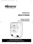
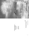
1
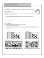
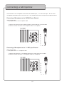
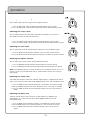
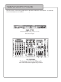
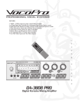
R
TM
THE SINGER'S ULTIMATE CHOICE
PV-1800
World’s First Active 15” Vocal Speaker
With Built in Digital Echo Mixer
owner ʼs manual
Table of Contents
FCC Information
...................................................
Listening for a Lifetime
...................................
3
4
Safety Instructions ............................................. 5
Welcome
...................................................................
Features and Specifications
........................
7
................................................................
8
Features
Specifications
Before Getting Started
Setting Up
Setting up the Speaker Stand
Mounting the Speakers
Voltage Selector
Switching the Voltage
Getting Connected
Connecting
Connecting
Connecting
Connecting
6
......................................
the Power
a Player or Mixer
to the RCA LINE IN Channel
to the XLR LINE IN Channel
9 - 10
Connecting to a Second Speaker .............. 11
Connecting to the XLR LINE OUT Channel
Connecting to the 1/4” LINE OUT Channel
Connecting a Microphone
.............................
12
Connecting a Microphone to the XLR MIC Input Channel
Connecting a Microphone to the RCA MIC Input Channel
Descriptions and Functions
..........................
13
...............................................................
14
Descriptions
Functions
Operations
Adjusting
Adjusting
Adjusting
Adjusting
Adjusting
Adjusting
the
the
the
the
the
the
Microphone Volume
Line In Level
Echo Level
Master Volume
Treble Tone
Bass Tone
Troubleshooting
Index
....................................................
15
............................................................................
16
2
FCC Information (U.S.A.)
1. IMPORTANT NOTICE: DO NOT MODIFY THIS
UNIT!: This product, when installed as indicated in the
instructions contained in this manual, meets FCC
requirements. Modifications not expressly approved by
Vocopro may void your authority, granted by the FCC, to
use this product.
2. IMPORTANT: When connecting this product to
accessories and/or another product use only high
quality shielded cables. Cable(s) supplied with this
product MUST be used. Follow all installation
instructions. Failure to follow instructions could void your
FCC authorization to use this product in the U.S.A.
CAUTION:
READ THIS BEFORE OPERATING YOUR UNIT
1. To ensure the finest performance, please read this
manual carefully. Keep it in a safe place for future reference.
2. Install your unit in a cool, dry, clean place - away from
windows, heat sources, and too much vibration, dust,
moisture or cold. Avoid sources of hum (transformers, v
motors). To prevent fire or electrical shock, do not expose to
rain and water.
3. Do not operate the unit upside-down.
3. NOTE: This product has been tested and found to
comply with the requirements listed in FCC Regulations,
Part 15 for Class "B" digital devices. Compliance with
these requirements provides a reasonable level of
assurances that your use of this product in a residential
environment will not result in harmful interference with
other electronic devices. This equipment
generates/uses radio frequencies and, if not installed
and used according to the instructions found in the
owner's manual, may cause interference harmful to the
operation of other electronic devices. Compliance with
FCC regulations does not guarantee that interference
will not occur in all installations. If this product is found
to be the source of interference, which can be
determined by turning the unit "Off" and "On", please try
to eliminate the problem by using one of the following
measures:
4. Never open the cabinet. If a foreign object drops into the
set, contact your dealer.
Relocate either this product or the device that is being
affected by the interference.
9. This unit consumes a fair amount of power even when the
power switch is turned off. We recommend that you unplug
the power cord from the wall outlet if the unit is not going to
be used for a long time. This will save electricity and help
prevent fire hazards. To disconnect the cord, pull it out by
grasping the plug. Never pull the cord itself.
Use power outlets that are on different branch (circuit
breaker or fuse) circuits or install AC line filter(s).
In the case of radio or TV interference, relocate/reorient
the antenna. If the antenna lead-in is 300-ohm ribbon
lead, change the lead-in to coaxial type cable.
If these corrective measures do not produce satisfactory
results, please contact your local retailer authorized to
distribute Vocopro products. If you can not locate the
appropriate retailer, please contact Vocopro, 1728
Curtiss Court, La Verne, CA 91750.
5. Place the unit in a location with adequate air circulation.
Do not interfere with its proper ventilation; this will cause the
internal temperature to rise and may result in a failure.
6. Do not use force on switches, knobs or cords. When
moving the unit, first turn the unit off. Then gently disconnect
the power plug and the cords connecting to other
equipment. Never pull the cord itself.
7. Do not attempt to clean the unit with chemical solvents:
this might damage the finish. Use a clean, dry cloth.
8. Be sure to read the "Troubleshooting" section on common
operating errors before concluding that your unit is faulty.
10. To prevent lightning damage, pull out the power cord
and remove the antenna cable during an electrical storm.
11. The general digital signals may interfere with other
equipment such as tuners or receivers. Move the system
farther away from such equipment if interference is
observed.
NOTE:
Please check the copyright laws in your country
before recording from records, compact discs,
radio, etc. Recording of copyrighted material may
infringe copyright laws.
CAUTION
The apparatus is not disconnected from the AC power
source so long as it is connected to the wall outlet,
even if the apparatus itself is turned off. To fully insure
that the apparatus is indeed fully void if residual power,
leave unit disconnected from the AC outlet for at least
fifteen seconds.
Voltage Selector (General Model Only)
Be sure to position the voltage selector to match the
voltage of your local power lines before installing the
unit.
220V
110V
3
Listening For A Lifetime
������������������������������������������������������������������������������������������������
����������������������������������������������������������������������������������������������
�������������������������������������������������������������������������������������������
��������������������������������������������������������������������������������������������������
���������������������������������������������������������������������������������������
������������������������������������������������������
��������������������������������������������������������������������������������������������
�����������������������������������������������������������������������������������������������
��������������������������������������������������������������������������
��������������������������
����������������������������������������������
����������������������������������������������������������������������������������������
��������������
����������������������������������������������������
�����������������������������������
���������������������������������������������������������������
������������������������������������������������������������������������������������������������������
�������������������������������������
������������������������������������������������������������������������������������������
�������������������������������������������������������������������������������������������������
���������������������������������������������������������������������������������������
�������������������������������������������������������������������������������������������������
���������������������������
������
��
��
��
��
��
��
�������
����������������������������������
����������������������������������������������������
����������������������������������
�����������������������������������������
��������������������������������������������
�������������������������������������������������������������
��������������������������������������������������������������
������
��
���
���
���
���
�������
����������������������������������������������
�����������������������������������������
��������������������������������������
������������������������
��������������������
���������������������������������������������������������
4
Safety Instructions
8. Ventilation - The appliance should be situated so its
location does not interfere with its proper ventilation. For
example, the appliance should not be situated on a bed,
sofa, rug, or similar surface that may block the
ventilation slots.
CAUTION
RISK OF SHOCK
CAUTION: To reduce the risk of electric shock,
do not remove cover (or back). No
user-serviceable parts inside. Only refer
servicing to qualified service personnel.
9. Heat - The appliance should be situated away from
heat sources such as radiators, heat registers,
stoves, or other appliances (including amplifiers)
that produce heat.
10. Power Sources - The appliance should be
connected to a power supply only of the type described
in the operating instructions or as marked on the
appliance.
Explanation of Graphical Symbols
The lightning flash & arrowhead
symbol, within an equilateral triangle,
is intended to alert you to the
presence of danger.
11. Grounding or Polarization - Precautions should be
taken so that the grounding or polarization means of
an appliance is not defeated.
12. Power-Cord Protection - Power-supply cords
should be routed so that they are not likely to be walked
on or pinched by items placed upon or against them,
paying particular attention to cords at plugs,
convenience receptacles, and the point where they exit
from the appliance.
The exclamation point within an
equilateral triangle is intended to alert
you to the presence of important
operating and servicing instructions.
WARNING
13. Cleaning - Unplug this unit from the wall outlet
before cleaning. Do not use liquid cleaners or
aerosol cleaners. Use a damp cloth for cleaning.
To reduce the risk of fire or electric shock, do
not expose this unit to rain or moisture.
14. Power lines - An outdoor antenna should be
located away from power lines.
1. Read Instructions - All the safety and operating
instructions should be read before the appliance is
operated.
15. Nonuse Periods - The power cord of the appliance
should be unplugged from the outlet when left unused
for a long period of time.
2. Retain Instructions - The safety and operating
instructions should be retained for future reference.
16. Object and Liquid Entry - Care should be taken so
that objects do not fall and liquids are not spilled into the
enclosure through openings.
3. Heed Warnings - All warnings on the appliance and in
the operating instructions should be adhered to.
17. Damage Requiring Service - The appliance should
be serviced by qualified service personnel when:
4. Follow Instructions - All operating and use
instructions should be followed.
A.
B.
C.
D.
The power supply cord or plug has been damaged; or
Objects have fallen into the appliance; or
The appliance has been exposed to rain; or
The appliance does not appear to operate normally
or exhibits a marked change in performance; or
E. The appliance has been dropped, or the enclosure
damaged.
5. Attachments - Do not use attachments not
recommended by the product manufacturer as they may
cause hazards.
6. Water and Moisture - Do not use this unit near water.
For example, near a bathtub or in a wet basement and
the like.
18. Servicing - The user should not attempt to service
the appliance beyond that described in the operating
instructions. All other servicing should be referred to
qualified service personnel.
7. Carts and Stands - The appliance should be used
only with a cart or stand that is recommended by the
manufacturer.
Note:
To CATV system installer's (U.S.A.): This reminder is
provided to call the CATV system installer's attention to
Article 820-40 of the NEC that provides guidelines for
proper grounding and, in particular, specifies that the
cable ground shall be connected as close to the point of
cable entry as practical.
7 A. An appliance and cart combination
should be moved with care. Quick stops,
excessive force, and uneven surfaces may
cause an overturn.
5
Welcome.
And Thank you for purchasing the PV-1800 from VocoPro, your ultimate choice in
Karaoke entertainment! With years of experience in the music entertainment business,
VocoPro is a leading manufacturer of Karaoke equipment, and has been providing
patrons of bars, churches, schools, clubs and individual consumers the opportunity to
sound like a star with full-scale club models, in-home systems and mobile units. All our
products offer solid performance and sound reliability, and to further strengthen our
commitment to customer satisfaction, we have customer service and technical support
professionals ready to assist you with your needs. We have provided some contact
information for you below.
VocoPro
1728 Curtiss Court
La Verne, CA 91750
Toll Free: 800-678-5348
TEL: 909-593-8893
FAX: 909-593-8890
Customer Service & General Information
[email protected]
Tech Support
[email protected]
Remember Our Website
Be sure to visit the VocoPro website www.vocopro.com for the latest information on new
products, packages and promos. And while you’re there don’t forget to check out our
Club VocoPro for Karaoke news and events, chat rooms, club directories and even a
Service directory!
We look forward to hearing you sound like a PRO, with VocoPro, your ultimate choice in
Karaoke entertainment.
FOR YOUR RECORDS
Please record the model number and serial number below, for easy reference, in case of loss or theft.
These numbers are located on the rear panel of the unit. Space is also provided for other relevant information
Model Number .................................................................................................................................
Serial Number ..................................................................................................................................
Date of Purchase .............................................................................................................................
Place of Purchase ...........................................................................................................................
6
Features and Specifications
Features
•
•
•
•
•
•
•
•
•
•
•
•
•
•
•
•
2-way 15” active speaker
Built-in 350W mono power amp with Digital Echo
Powers a second un-powered speaker
Vocal speaker designed for live entertainment
Mic input channel with one ¼” and one XLR jack
RCA L/R Line In channel
Mono XLR Line In channel
Line Out channel with one ¼” and one XLR jack
Master volume control
Mic input level control
Line In level control
Bass and Treble tone controls
Digital Echo level control
Power LED indicates when the power on
Peak LED indicates any signal peaks
110V / 220V voltage selector
Specifications
Power rating ....................................... 400W peak / 200W RMS
Impedance .......................................... 8Ω
Sensitivity ............................................ 100dB
Frequency response ............................. 20Hz -- 20kHz
Shipping dimensions ............................. 19¾” (L) x 19” (W) x 26¼” (H)
Shipping weight .................................... 55 lbs.
The PV-1800 200W Powered Speaker system is self-powered and does not rely on an external amplifier for
power. This means you can connect any mixer, player or other audio device directly to its stereo RCA Line In inputs
for instant sound.
Before Getting Started
Follow this quick setup guide for basic step-by-step instructions on setting up your PV-1800 powered speaker.
Because every system varies, you may be required to purchase additional/longer cables, adaptors, etc. in order
to integrate the PV-1800 into your system.
The following items should be included with your PV-1800:
• 1 PV-1800 Powered Speaker
• 1 Power cord
7
Setting Up
Setting up the Speaker Stand
Setup each SS-88 speaker stand by extending the support lefts to a
position that is stable and tighten the tension mechanism firmly. Each
end of the SS-88 pole has a particular diameter fitted for common
speakers’ mounting cavities. If the SS-88 pole does NOT fit flush into the
mounting adapter on the PV-1800, loosen the SS-88 pole and reverse it
in the stand and then remount the speaker.
Mounting the Speaker(s)
Once the adapter is securely attached to the speaker:
1. Place the PV-1800 on the SS-88 speaker pole
2. Fasten the fastener on the adapter until it is secured tightly
3. Repeat this for the next speaker
Voltage Selector
The PV-1800 has a voltage selector on the rear panel that switches
between two voltage settings:
115V - North America, Canada, some South America
220V - Europe, Asia, some South America
Note: The PV-1800 comes preset to 115V and will only need to be
switched if it is being used in a region that requires 220V.
Switching the Voltage
1. Switch the selector to the proper voltage
CAUTION: Using the speakers while set to the wrong voltage can result in permanent damage and will void the
warranty. Make sure you have set the PV-1800 to the correct voltage before using.
8
Getting Connected
Connecting the Power
Before connecting the power cord make sure that the PV-1800’s power switch is switched off.
What you will need:
• AC Power Cord (included)
• Surge protector/power strip.
Note: VocoPro recommends that you use a surge protector to prevent permanent damage to
your speakers, caused by a power surge.
1. Connect the correct end of the power cord to the AC input on the PV-1800’s rear panel
2. Connect the 3-pronged end to a 3-pronged out let on a surge protector or wall outlet
Connecting a Player or Mixer
Connecting to the RCA LINE IN Channel
What you will need:
• Player or Mixer with RCA Left and Right (red & white) audio outputs
• L/R (red & white) stereo RCA audio cables
1. Connect one end of each RCA cable to the L/R (red & White) RCA outputs on your player or mixer
2. Connect the other ends of the RCA cables to the L/R (red & white) LINE IN RCA inputs on the PV-1800’s
rear panel
�������
�������
�����
������������������
����������������������������������������
9
Getting Connected
ected cont . . .
Connecting to the XLR LINE IN Channel
What you will need:
• Player or Mixer with and XLR audio output
• XLR audio cable
1. Connect one end of the XLR cable to the XLR output on a mixer
2. Connect the other end of the XLR cable to the LINE IN XLR jack on PV-1800’s rear panel
�������
�����
����������������������������������������
10
Connecting to a Second Speaker
eak
eaker
The PV-1800 can be connected to a second powered speaker using its XLR or ¼” LINE OUT channels.
Connecting to the XLR LINE OUT Channel
What you will need:
• An powered speaker with an XLR audio input
• XLR cable
1. Connect one end of the XLR cable to the LINE OUT XLR jack on the PV-1800
2. Connect the other end of the XLR cable to the XLR input on the powered speaker
�������
�������
�����
Connecting to the ¼” LINE OUT Channel
What you will need:
• An powered speaker with a ¼” audio input
• ¼” cable
1. Connect one end of the ¼” cable to the LINE OUT ¼” jack on the PV-1800
2. Connect the other end of the ¼” cable to the ¼” input on the powered speaker
�������
�������
�����
11
Connecting a Microphone
The PV-1800 has one microphone channel with two available inputs, a ¼” and an XLR input. You can have a
microphone connected to each at the same time. Use the MIC LEVEL control to adjust the microphone volume.
Connecting a Microphone to the XLR MIC Input Channel
What you will need:
• A microphone with an XLR microphone cable
1. Connect one end of the XLR microphone cable to the XLR MIC jack on the PV-1800
2. Connect the other end of the XLR microphone cable to a microphone
�������
Connecting a Microphone to the ¼” MIC input Channel
What you will need:
• A microphone with a ¼” microphone cable
1. Connect one end of the ¼” microphone cable to the ¼” MIC jack on the PV-1800
2. Connect the other end of the ¼” microphone cable to a microphone
�������
12
Descriptions and Functions
Descriptions and Functions
1. ¼” MIC input - Connect a microphone
�
�
here using a ¼” microphone cable
2. XLR MIC input - Connect a microphone here using an XLR microphone
cable
�
3. RCA LINE IN channel - Connect a
player or mixer here using L/R (red
& white) RCA cables
�
4. XLR LINE IN channel - Connect a
mixer or receiver here using an XLR
cable
5. ¼” LINE OUT channel - Connect to
�
�
a second powered speaker
with a ¼” input
6. XLR LINE OUT channel - Connect to
�
a second powered speaker
�
with a XLR input
7. MIC LEVEL control - Controls the
volume for the microphone that is
��
connected to the PV-1800’s ¼” or
�
XLR microphone input. Turn the
control towards MIN to lower the
��
microphone level and towards MAX
to raise it.
8. LINE IN LEVEL control - Controls the
volume for the player or mixer that is
��
connected to the PV-1800’s ¼” or
XLR LINE IN jack. Turn the control
��
towards MIN to lower the level and
��
towards MAX to raise it.
9. ECHO control - Controls how much
��
echo effect is present in the micro��
phone signal. T
Turn the control towards 0 to decrease the echo effect
��
and towards 10 to increase it.
10. MASTER volume control - Controls
the master output volume. Turn the
control towards MIN to lower the
master output volume and towards
MAX to raise it.
11. TREBLE control - Controls the amount of treble applied to the master output (microphone and music). Turn
towards -12 to cut the treble and towards +12 to add treble. Set at the middle position for no treble.
12. BASS control - Controls the amount of bass applied to the master output (microphone and music). Turn to
wards -12 to cut the bass and towards +12 to add bass. Set at the middle position for no bass.
13. Clip LED - Indicates if any clipping is occurring
14. Power LED - Indicates when the power is on
15. POWER switch - Turns the PV-1800 on and off
16. AC Input - Connect the included power cable here
17. Voltage selector - Allows you to switch the voltage level to match the region you are in. Select 115V for North
America, Canada, some South America. Select 220V for Europe, Asia, some South America.
13
Operat
Operations
Adjusting the Microphone V
Volume
Use the MIC LEVEL control to adjust the microphone volume
1. Turn the MIC LEVEL control clockwise towards MAX to raise the level
2. Turn the MIC LEVEL control counter-clockwise towards MIN to lower the level
Adjusting the Line In Level
Use the LINE IN LEVEL control to adjust the level for the player or mixer that is
connected to the RCA or XLR LINE IN channel.
1. Turn the LINE IN LEVEL control clockwise towards MAX to raise the level
2. Turn the LINE IN LEVEL control counter-clockwise towards MIN to lower the level
Adjusting the Echo Level
You can adjust how much of the echo effect is present in the microphone signal
1. Turn the ECHO control clockwise towards 10 to raise the amount of echo
2. Turn the ECHO control counter-clockwise towards 0 to lower the amount of echo
Adjusting the Master Volume
You can adjust the master volume using the MASTER control
1. Turn the MASTER control clockwise towards MAX to raise the volume
2. Turn the MASTER control counter-clockwise towards MIN to lower the volume
NOTE: If the MASTER volume is turned up high but no microphone and/or music can
be heard, make sure the MIC LEVEL and/or LINE IN LEVEL controls are turned up
high enough.
Adjusting the Treble Tone
The treble control adjusts how much treble or high-frequency is applied to the overall
output. This means that the treble will be applied to both music and microphone vocals.
1. Turn the TREBLE control clockwise towards +12 to boost the amount of treble
2. Set the TREBLE control to the center position or 0 for a flat tone or no treble
3. Turn the TREBLE control counter-clockwise towards -12 to cut the amount of
treble
Adjusting the Bass Tone
The bass control adjusts how much bass or high-frequency is applied to the
overall output. This means that the bass will be applied to both music and
microphone vocals.
1. Turn the BASS control clockwise towards +12 to boost the amount of bass
2. Set the BASS control to the center position or 0 for a flat tone or no bass
3. Turn the BASS control counter-clockwise towards -12 to cut the amount
of bass
14
Troubleshooting
The power is not turning on
• Make sure the power cable is connected fimly to the PV-1800 and the power outlet
• If you are using a surge protector / power strip, make sure it is plugged in and turned on
• Try a different power outlet
There is no sound coming out of either of the speakers
•
•
•
•
•
•
•
Make
Make
Make
Make
Make
Make
Make
sure
sure
sure
sure
sure
sure
sure
the power is on
the Master volume is turned up
the Line In Level control is turned up loud enough
the Mic Level control is turned up loud enough if you are using a microphone
all cables are securely connected to the proper jacks
there are no damaged or bad cables
all other devices, i.e. players, mixers, etc., are turned on and their volume is turned up
There is no sound coming out of the second speaker
• Make sure the speaker cable is firmly attached to both speakers
• Try a different speaker cable
There is a lot of feedback or a high-pitched squealing
• Lower the treble on the speaker, mixer, etc.
• Try repositioning the microphone if you are using a microphone
• Lower the microphone volume, mixer volume, player volume, etc.
The audio sounds muffled and unclear
• Lower the bass on the speaker, mixer, etc.
• Make sure the microphone(s), mixer, player, etc. are working properly and are set to the correct settings
There is a loud popping sound coming out of the speakers
• There may be a bad cable somewhere in the system
• Make sure there are no damaged microphones
15
Index
Symbols
¼” LINE OUT 13
¼” MIC input 13
D
P
A
Descriptions and Functions 13
E
Power LED 13
Power rating 7
POWER switch 13
ECHO control 14
R
F
RCA LINE IN 13
Features 7
Frequency response 7
S
AC Input
Adjusting
Adjusting
Adjusting
Adjusting
Adjusting
Adjusting
13
the
the
the
the
the
the
Bass Tone 14
Echo Level 14
Line In Level 14
Master Volume 14
Microphone Volume 14
Treble Tone 14
B
BASS control 13
C
Clip LED 13
Connecting a Microphone 12
Connecting a Microphone to the ¼” MIC
input Channel 12
Connecting a Microphone to the XLR
MIC Input Channel 12
Connecting a Player or Mixer 9
Connecting the Power 9
Connecting to a Second Speaker 11
Connecting to the ¼” LINE OUT
Channel 11
Connecting to the RCA LINE IN
Channel 9
Connecting to the XLR LINE IN
Channel 9
Connecting to the XLR LINE OUT
Channel 11
G
Getting Connected 9
I
Sensitivity 7
Setting Up 8
Setting up the Speaker Stand 8
Specifications 7
Switching the Voltage 8
T
Impedance 7
L
TREBLE control 13
Troubleshooting 15
LINE IN LEVEL 13
V
M
MASTER volume control 13
MIC LEVEL 14
Mounting the Speaker(s) 8
Voltage Selector 8
Voltage selector 13
X
XLR LINE IN 13
XLR LINE OUT 13
XLR MIC input 13
O
Operations 14
16
Featured VocoPro P
Products
Here are some of the other great VocoPro products featured in this manual. You can find
more information at our website: www.vocopro.com.
DVG-777K
Multi-Format USB/DVD/CD+G
Karoake Player
KJ-7808RV
Professional KJ/DJ/VJ Mixer with
DSP Mic Effect and Digital Key Control
N
Notes
Notes
R
TM
THE SINGER'S ULTIMATE CHOICE
C
������������
�����
���������������