1
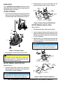
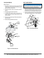
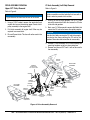
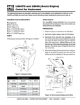
HHN Ride-On Trowel Clutch Retrofit Kit Installation Instructions The following instructions are intended to assist the user in the installation of a Hilliard CVT clutch system. The Hilliard clutch system replaces the Comet CVT system. Please read all assembly instructions before installing the kit. REQUIRED TOOLS 1 Hammer Torque Wrench 3/8 Ratchet 3/8, 7/16, 1/2, 3/4, 9/16, 5/8, 15/16, 13mm Sockets 3/16 and 1/4 Allen sockets Open/box-end wrenches Misc. Pry-Bars CV Joint Grease Grease Gun w/Multi-purpose grease 2x4 wood block Forklift/Hoist Clutch Puller Heavy Duty Jack Stands Scotch-brite Pad Brake Cleaner 5 BLUE LOCTITE 6 3 31 9 18 PARTS 2 Verify that all parts are accounted for. See Figure 1, Figure 2 and Table 1. 28 22 29 1 21 19 16 23 15 25 26 20 11 10 14 27 7 8 4 32 34 RED LOCTITE 13 RETAINING COMPOUND 12 17 PRIMER Figure 1. Clutch Retrofit Kit 33 24 30 3 Table2. 1. Clutch HHN CVTRetrofit Kit Parts Kit Figure Item Qty. Part No. Description Remarks 1 1 22581 Kit, HHN CVT Replacement Includes items 2 thru 34 2 4 0131 A Screw, HHC 1/4-20 X 3/4 3 14 0948 Washer, Flat SAE 1/4 4 1 30107 Screw, FHCS, 3/8-16 X 1.25 LH Thread 5 1 1477 Loctite™ #242 6 6 1579 Screw, HHC 1/4-20 X .5 7 1 30110 Spacer, CSK Ø1.375 Ø.391x.281 8 3 9165 Screw, HHFS 1/4-28 X 3/4 9 4 10024 Nut, Nyloc 1/4-20 10 4 10133 Nut, Nyloc 3/8-16 11 4 13351 Washer, Flat 3/8" 12 5 11534 Nut, U-Type 1/4-20 Screw, HHWS 1/4-20 X 3/4 13 5 11819 14 1 20116 O-Ring 15 1 20363 Key, Cross Shaft 16 5 22021 Screw, Hex Flange M8 17 1 22579 Shroud, Clutch 18 2 22588 Mount, Fuel Tank 19 1 23363-1 Clutch, Upper 20 1 23363-2 Pulley, Lower Belt, CVT Clutch Blue Hilliard 21 1 23365 22 1 23368 Stub Shaft 23 1 23369 Washer, Step 7/16 Hilliard 24 1 23678 Puller Hilliard 25 1 23377 Screw, HHC 7/16-20 X 6.5 26 1 30103 Cross Shaft Assy, LH Shaft 27 1 23433 Coupler CV-Joint 28 1 23436 Alignment Gauge Sleeve, Alignment Gauge 29 1 23415 30 10 11773 Shims 31 2 22068 Fuel Hose Clamps 32 1 19379-014 Loctite™ 271 33 1 32441 Primer, Loctite™ 7649 34 1 32434 Retaining Compound, Loctite™ 609 .031 Thickness HHN — CLUTCH RETROFIT KIT INSTALLATION INSTRUCTIONS P/N 23444 — REV. #7 (04/25/14)— PAGE 1 OF 12 Red WORK SAFELY! Only a qualified service technician with proper training should perform this installation. Follow all shop safety rules when performing this installation. 2. Remove battery tray from frame. Set battery tray and mounting hardware aside in a clean, safe place. REMOVE SPLASH PAN LOWER DRIVE PULLEY GUARD REMOVE BATTERY TRAY LIFTING THE TROWEL 1. Attach one end of a lifting strap or chain around the lift loops on each side of the trowel. Attach the other end of the lifting strap or chain to the lifting device (Figure 3). REMOVE BATTERY PUSH CABLE BACK THRU BATTERY TRAY REMOVE REMOVE BATTERY TRAY BATTERY TRAY MOUNTING HARDWARE LIFT LIFT Figure 4. Battery Removal (HHN 34TVD) BATTERY REMOVAL (HHN-31V ONLY) Refer to Figure 5. 1. Disconnect both battery cables from the battery. LIFTING HOOK 2. Locate fuel pump attached to the backside of the battery box. Disconnect the fuel line from the fuel tank. Remove fuel pump from battery box. Set pump aside in a clean, safe place. LIFTING STRAP S E R IE S LIFT LOOP 3. Remove battery tray and splash pan from frame. Set battery tray, splash pan, and mounting hardware aside in a clean safe place. NOTICE If trowel blades have not been removed, they must be pitched flat in order to allow removal of splash pan. JACK STANDS REMOVE SPLASH PAN Figure 3. Lifting the Trowel 2. Next, place the trowel on heavy duty jack stands. CAUTION REMOVE BATTERY Trowel blades are sharp. Keep clear of blades while performing procedure. It is recommended that trowel blades are removed to prevent injury. PUSH CABLE BACK THRU BATTERY TRAY BATTERY REMOVAL (HHN-34TVD ONLY) Reference Figure 4. 1. Disconnect both battery cables from the battery. Remove splash pan from battery tray and trowel frame. Set pan aside in a clean, safe place. NOTICE If trowel blades have not been removed, they must be pitched flat in order to allow removal of splash pan. REMOVE REMOVE BATTERY TRAY BATTERY TRAY MOUNTING HARDWARE IN-LINE FUEL FILTER REMOVE FUEL PUMP REMOVE CLAMP/HOSE FROM FUEL TANK TO FUEL CARBURETOR REMOVE BOLTS REMOVE BATTERY TRAY Figure 5. Battery Removal (HHN 31V) HHN — CLUTCH RETROFIT KIT INSTALLATION INSTRUCTIONS P/N 23444 — REV. #7 (04/25/14) — PAGE 2 OF 12 FUEL TANK REMOVAL BELT GUARD REMOVAL NOTICE Refer to Figure 6. 1. Remove the 2 bolts that secure the spare CVT belt holder (Figure 6) to the fuel tank. Remove and discard spare belt holder and spare belt. 2. Place fuel shut-off valve on fuel tank to the OFF position. 3. Disconnect fuel lines from the fuel tank. 4. On HHN-34TVD models, either plug return port (to prevent leaking) on fuel tank or pour fuel into a fuel safety container. 5. Remove fuel tank from frame. Set fuel tank aside in a clean safe place. 6. Retain mounting hardware for later use. The front panel of the trowel can be removed to allow easier access for the removal of the belt guard. 1. Remove the retaining hardware that secures the left belt guard panel. Remove panel and discard. This item will not be used in the reassembly. Reference Figure 7 2. Remove rear belt guard panel. Set rear belt guard panel and mounting hardware aside in a clean safe place. MUFFLER BELT GUARD COVER REMOVE SCREWS (3 PLACES) RETAIN LE FT TOP REMOVE SCREWS (4 PLACES) REMOVE AND DISCARD REMOVE SPARE BELT HOLDER REMOVE SPARE BELT HOLDER MOUNTING HARDWARE R REA LOWER PULLEY E NG INE F UE L ON DISCARD SPARE BELT LY REMOVE FUEL TANK MOUNTING HARDWARE FUEL SHUT-OFF VALVE EN G IN Figure 7. Belt Guard Removal REMOVE CLAMP/HOSE E F U TO FUEL FILTER EL ON LY PLUG FITTING WHEN REMOVING FUEL LINE RETURN LINE HHN-34TVD/DIESEL ONLY EN GIN E FU EL O N LY FUEL Figure 6. Fuel Tank Removal HHN — CLUTCH RETROFIT KIT INSTALLATION INSTRUCTIONS P/N 23444 — REV. #7 (04/25/14)— PAGE 3 OF 12 DRIVE ASSEMBLY REMOVAL Upper CVT Pulley Removal CV Axle Assembly (Left-Side) Removal Refer to Figure 8. Refer to Figure 8. NOTICE NOTICE Figure 8 shows the view from the rear of the trowel. 1. Using a 15/16" socket, remove the center bolt and washer that secure the existing upper Comet clutch/ pulley assembly to the engine shaft 2. Pull clutch assembly off engine shaft. Puller may be required to remove clutch. 3. Discard Comet clutch. This item will not be used in the reassembly. Spider assemblies must be locked to the frame with a chain in order to prevent clutch rotation. 1. Starting at the left-side gearbox, use a 1/4" Allen wrench to remove the 3 bolts that secure the CV axle to the left-side gearbox. 2. Next, use a 1/4" Allen wrench to remove the 3 bolts that secure the CV axle to the lower drive pulley coupler. NOTICE Note that the 3 bolts securing the CV axle to the coupler are shorter than those securing the CV axle to the gearbox. Remember bolt orientation for reassembly. 3. Remove CV axle assembly. Set CV axle assembly and mounting hardware aside in a clean safe place. 4. Remove and discard CVT belt. It will not be used in the reassembly. ENGINE CRADLE ENGINE FLYWHEEL RIGHT-SIDE GEARBOX REMOVE UPPER DRIVE PULLEY/CLUTCH REMOVE (3 PLACES) (OPTIONAL) REMOVE REMOVE CVT BELT LEFT-SIDE GEARBOX REMOVE CV-AXLE (OPTIONAL) REMOVE (3 PLACES) COUPLER REMOVE CROSS SHAFT REMOVE CV-AXLE REMOVE REMOVE (3 PLACES) LOWER DRIVE PULLEY REMOVE (3 PLACES) REMOVE (4 PLACES) GEARBOX COUPLER Figure 8. Drive Assembly Removal HHN — CLUTCH RETROFIT KIT INSTALLATION INSTRUCTIONS P/N 23444 — REV. #7 (04/25/14) — PAGE 4 OF 12 Disconnect/Remove CV Axle Assembly (Right-Side) NOTICE Disconnecting the Right-Side CV Axle Assembly from the gearbox is optional. Inspect rubber boots for damage or dirt. If CV Axle is in good condition, it is not necessary to remove it from the gearbox. Removal of the bolts securing CV Axle to the cross shaft coupler is mandatory. STUB SHAFT INSTALLATION 1. Remove paint from flywheel mounting surface using Scotch-brite pad (no sanding). See Figure 10. STUB SHAFT PILOT RING FLYWHEEL MOUNTING SURFACE NO DINGS ON EDGE Refer to Figure 8. 1. Remove the 3 bolts that secure the CV axle to the right-side gearbox (optional). OUTER RING NO DINGS ON EDGE 2. Remove the 3 bolts that secure the CV axle to the cross shaft coupler. 3. Remove CV axle assembly (optional). Set CV axle assembly and mounting hardware aside in a clean safe place. Cross Shaft/Lower Pulley Removal 1. Using a 3/8" ratchet with a 9/16" socket, remove the 4 nuts and washers that secure the cross shaft bearing blocks to the engine cradle. 2. Remove and discard cross shaft and lower pulley assemblies. These items will not be used in the reassembly. Stub Shaft Removal Reference Figure 9. 1. Using a 13mm socket, remove the 5 bolts and washers that secure the stub shaft to the engine coupler. NOTICE Wedge a 2x4 block of wood between flywheel and trowel frame to prevent flywheel rotation. REMOVE PAINT NO SANDING USE SCOTCH BRITE PAD Figure 10. Flywheel Mounting Surface 2. Ensure that there are no dings on the edges of the stub shaft pilot ring and the outer ring (See Figure 10). Use a flat abrasive stone to remove burrs from around any dings. 3. Using a 13mm socket, install new stub shaft, P/N 23368, with M8-1.25 x 20 mm hex flange screws (5), P/N 22021, onto engine coupler. DO NOT apply antiseize compound to stub shaft. See Figure 11. NOTICE Blue Loctite™ or Loctite™ patch is required. Reapply Loctite™ if reinstalling screws. NOTICE Wedge a 2x4 block of wood between flywheel and trowel frame to prevent flywheel rotation so screws can be fully tightened. 4. Torque stub shaft mounting screws to 34 ft-lbs (46 N·m) in a star pattern. See Figure 11. 2. Remove and discard stub shaft and mounting hardware. These items will not be used in the reassembly. ENGINE FLYWHEEL DO NOT APPLY ANTI-SEIZE COMPOUND REMOVE STUB SHAFT FLYWHEEL 1 4 2 ENGINE COUPLER REMOVE (5 PLACES) Figure 9. Stub Shaft Removal 3 5 STAR PATTERN SEQUENCE TORQUE TO 34 FT-LBS (46 N·m) IN A STAR PATTERN STUB SHAFT (P/N 23368) ENGINE COUPLER M8-1.25 X 20 MM GRD 10.9 HEX FLANGE SCREW (5) (P/N 22021) Figure 11. Stub Shaft Installation HHN — CLUTCH RETROFIT KIT INSTALLATION INSTRUCTIONS P/N 23444 — REV. #7 (04/25/14)— PAGE 5 OF 12 CROSS SHAFT INSTALLATION 1. Remove dust cap located on top of bearing (Figure 12). 2. Using a grease gun, grease both bearings. Use multipurpose grade grease. 3. Reinstall dust cap to prevent contamination of the bearing. GREASE GUN STUB SHAFT GAUGE BODY BEARING ZERK FITTING DUST CAP ALIGNMENT BOLT TORQUE TO 20 FT-LBS (27.1 N·m) GAUGE ARM GAUGE PIN Figure 12. Bearing Lubrication 4. Using a 3/8" ratchet with a 9/16" socket, install new cross shaft assembly (Figure 13), P/N 30103, with 3/816 nyloc nuts (4), P/N 10133, and 3/8 flat washers (4), P/N 13351, onto engine cradle. 5. Torque cross shaft mounting screws to 30 ft-lbs (40 N·m). GAUGE SLEEVE CROSS SHAFT Figure 14. Cross Shaft Alignment 4. Rotate gauge arm and remove gauge sleeve. Install shims as required. 5. Reinstall gauge sleeve onto cross shaft. Insert .032" feeler gauge (Figure 15) between gauge pin and gauge sleeve. NOTICE The gauge sleeve must be held and pressed firmly against the cross shaft bearing when using a feeler gauge to provide the most accurate measurement. ENGINE CRADLE 6. If .032" feeler gauge fits between gauge pin and gauge sleeve, re-shim until feeler gauge will not pass between gauge pin and gauge sleeve. CROSS SHAFT ASSY. (P/N 30103) TORQUE TO 30 FT-LBS (40 N·m) 3/8-16” (4) NYLOC NUT (P/N 10133) 3/8” (4) FLAT WASHER (P/N 13351) Figure 13. Cross Shaft Installation CROSS SHAFT ALIGNMENT See Figure 14. 1. Install gauge sleeve onto cross shaft. 2. Install gauge body onto stub shaft. Torque alignment bolt to 20 ft-lbs (27.1 N·m). 3. Measure the distance between the gauge pin and gauge sleeve with feeler gauge. This distance is an indication of the number of shims that will be required. 03 2 FEELER GAUGE (.032”) ADD SHIMS AS REQUIRED Figure 15. Shimming HHN — CLUTCH RETROFIT KIT INSTALLATION INSTRUCTIONS P/N 23444 — REV. #7 (04/25/14) — PAGE 6 OF 12 LOWER PULLEY (CVT) INSTALLATION 8. Torque 1/4-28 x 3/4" screws (3) to 10 ft-lbs (13.6 N·m). Reference Figure 16. 9. Torque 3/8-16 x 1.25" LH thread retaining screw to 31ft-lbs (42.03 N·m). 1. Apply primer (Loctite 7649, P/N 32441) to the cross shaft and key way in the shaded area shown in Figure 16. 1. Using retaining compound ( P/N 32434), apply to cross shaft and key way until coverage is complete with a minimum coating thickness of 1/16 of an inch. 2. Mount lower pulley (P/N 23363-2) and key (20363) onto cross shaft. KEY (P/N 20363) SPACER (P/N 30110) ENGINE CRADLE 10. Place the new CVT belt (P/N 23365) over the lower pulley. Do not attempt to squeeze the belt into the pulley groove yet. 11. Reconnect left-side CV Axle Assembly. See “CV Axle Reinstallation/Reconnection” section. CV Axle Reinstallation/Reconnection Before installing the CV axle assembly, ensure rubber boots are not cracked or worn (Figure 17). If boots are damaged, replace immediately. CV BOOT O-RING (P/N 20116) 1/4-28X3/4” SCREW HHFS (3) (P/N 9165) RED LOCTITE 3/8-16X1.25” TORQUE TO TORQUE TO SCREW, FHCS 10 FT-LBS 31 FT-LBS LH THREAD (13.6 N·m) (42.03 N·m) (P/N 30107) TORN OR CRACKED CROSS APPLY PRIMER (P/N 32441) THEN SHAFT RETAINING COMPOUND (P/N 32434) TO SHADED AREA (LOCTITE 271 P/N 19379-014) COUPLER (P/N 23433) LOWER PULLEY (P/N 23363-2) Figure 16. Lower Pulley Installation 3. Next, mount coupler (23433) onto lower pulley with O-ring (P/N 20116) placed between lower pulley and coupler. 4. Secure coupler with 1/4-28 x 3/4" screws (P/N 9165). 5. Clean the threads of 3/8-16 x1.25 LH thread retaining screw (P/N 30107) with brake cleaner. Apply red loctite (P/N 19379-014) to the threads. 6. Insert 3/8-16 x 1.25" LH thread retaining screw (P/N 30107) and spacer (P/N 30110) into cross shaft. 7. Once lower pulley has been mounted to shaft, wipeaway any and all retaining compound. NOTICE It is extremely important that this unit must not be run for a period of at least 24 hours. The retaining compound needs to cross link and become completely cured during this time period. NOTICE Before mounting screws can be torqued, the RightSide CV Axle Assembly must be reinstalled (if applicable)/reconnected. See “CV Axle Reinstallation/ Reconnection” section. Figure 17. CV Boot Inspection 12. If CV axle assembly is dirty or covered with debris, clean with a mild soap or solvent. 13. If necessary, grease CV axle as required. 14. Apply a thin coat of RTV silicone (Figure 18) to mating surfaces of CV axle assembly. RTV SILICONE APPLY SILICONE TO CV-JOINT MATING SURFACES RTV SILICONE Figure 18. Applying RTV Silicone 15. Connect right-side CV axle assembly to right-side gearbox coupler (if applicable) and cross shaft coupler. Connect left-side CV axle assembly to lower pulley coupler and left-side gearbox coupler Reference Figure 22. 16. Torque all coupler mounting hardware to 12 ft-lbs. PARTIAL REASSEMBLY / LOWERING TROWEL The trowel must be lowered back to the ground prior to fully installing the belt and upper pulley assembly. 1. Before lowering trowel back onto the ground, reinstall splash pan, battery tray, and battery. For HHN-31V models, be sure to install fuel pump. Reference Figure 4 and Figure 5. HHN — CLUTCH RETROFIT KIT INSTALLATION INSTRUCTIONS P/N 23444 — REV. #7 (04/25/14)— PAGE 7 OF 12 2. Lower trowel onto the ground. Follow all heavy lifting safety precautions. LOWER PULLEY BELT INSTALLATION 1. With the CVT belt placed over the lower pulley, squeeze the belt (Figure 19) and pull the belt upwards and towards the rear of the trowel. This will spread open the faces of the lower drive pulley. 2. Once CVT belt has been placed into upper pulley grooves, mount Hilliard clutch assembly onto stub shaft using 7/16-20 x 6.5" clutch retaining screw (P/N 23377) and 7/16" step washer. See Figure 21. STUB SHAFT APPLY BLUE LOCTITE™ #242 (P/N 1477) TORQUE TO 45 FT-LBS (61 N·m) CVT BELT (P/N 23365) 7/16-20 X 6.5” SCREW, HHC (P/N 23377) BLUE LOCTITE STEP WASHER (P/N 23369) CVT BELT PULL UPWARDS AND TOWARDS REAR OF TROWEL FIXED FACE MOVEABLE FACE LOWER PULLEY Figure 19. Holding Lower Pulley Open UPPER PULLEY BELT INSTALLATION 1. While holding the new Hilliard clutch (P/N 23363-1), place free end of CVT belt into upper pulley groves. Figure 21. Installing Clutch Assembly NOTICE Wedge a 2x4 block of wood between flywheel and trowel frame to prevent flywheel rotation so clutch retaining screw can be fully tightened. 3. Apply Blue Loctite™ #242 (P/N 1477) to clutch retaining screw and torque to 45 ft-lbs (61 N·m). PRE-TEST ASSEMBLY NOTICE CLUTCH (P/N 23363-1) DO NOT fully reassemble trowel until testing is complete. 1. Temporarily reinstall fuel tank onto trowel frame using existing mounting hardware. UPPER PULLEY 2. Reconnect fuel lines as referenced in Figure 6. Turn fuel shut-off valve to the ON position. 3. Reinstall front panel of trowel if previously removed. LOWER PULLEY Figure 20. Upper Pulley Belt Installation 4. Unlock spider assemblies. 5. Reconnect both battery cables to the battery. RED to the positive terminal, BLACK to the negative terminal. HHN — CLUTCH RETROFIT KIT INSTALLATION INSTRUCTIONS P/N 23444 — REV. #7 (04/25/14) — PAGE 8 OF 12 Figure 22 illustrates the new, fully-installed drive assembly. ENGINE CRADLE UPPER DRIVE PULLEY/CLUTCH STUB SHAFT RIGHT-SIDE GEARBOX ENGINE FLYWHEEL KEY CVT BELT LEFT-SIDE GEARBOX CV AXLE GEARBOX COUPLER CROSS SHAFT SHORTER SCREWS (3) SHIMS COUPLER CV AXLE LOWER DRIVE PULLEY GEARBOX COUPLER Figure 22. New Drive Assembly STARTING THE TROWEL/TESTING 1. While sitting in the operator’s position, start the trowel as referenced in the Operator’s Manual. Be sure to check the engine oil level prior to starting the engine. 4. Repeat procedure and check for axial sheave movement away from the engine. CAUTION The engine’s exhaust contains harmful emissions. ALWAYS have adequate ventilation when operating. Direct exhaust away from nearby personnel. AXIAL SHEAVE WARNING DO NOT stand in rotation plane of clutch system. Possibility exists of flying objects which could strike personnel and cause injury. 2. Run machine, bringing throttle up so clutch engages. Cycle the engine from idle to 3/4 throttle twice. Reduce throttle slowly and shut off engine. Remove key. 3. Check for axial sheave movement (see Figure 23) in the drive clutch in one direction by pushing the upper sheave face toward the engine. You should notice slight movement of the sheave in the direction you are pushing. ADD/REMOVE SHIM AS REQUIRED Figure 23. Axial Sheave Movement HHN — CLUTCH RETROFIT KIT INSTALLATION INSTRUCTIONS P/N 23444 — REV. #7 (04/25/14)— PAGE 9 OF 12 5. If axial movement is in one direction only, remove clutch using the clutch puller tool, P/N 23678. See Figure 24. PULLER (P/N 23678) Figure 24. Puller Fuel Tank Reassembly 1. Reinstall fuel tank onto trowel frame using new fuel tank mounting brackets (P/N 22588), 1/4-20 x 1/2 screws (P/N 1579), 1/4-20 x 3/4 screws (P/N 0131 A), 1/4" flat washers (P/N 0948) and 1/4-20 nuts (P/N 10024). See Figure 26. 6. If axial sheave will not move toward the engine, remove a shim from next to the cross shaft bearing. If axial sheave will not move away from the engine, add a shim next to the cross shaft bearing. See Figure 23. Re-shim as required until axial movement is present in both directions. Refer to Figure 14 and Figure 15. 7. Retest for correct axial sheave movement in both directions. ENGINE TROWEL REASSEMBLY New Belt Guard Installation 1. Install new left-side belt guard panel, P/N 22579, to upper belt guard panel, using 1/4-20 x 3/4" screws, P/N 11819, and U-Type nut, P/N 11534. 2. Reinstall existing rear belt guard panel to upper and left guard panels using existing hardware. Tighten all screws securely. 1/4-20 X 3/4 SCREW (5) (P/N 11819) EXISTING UPPER PANEL EXISTING HARDWARE LY 1/4-20 X1/2” SCREW (4) (P/N 1579) 1/4-20 NUT, NYLOC (4) (P/N 10024) 8. Disconnect the BLACK (negative) battery cable. 9. Remove and discard fuel tank mounting hardware. Move fuel tank out of the way in order to make room for new belt guard installation. FU EL ON MOUNT FUEL TANK (P/N 22588) 1/4-20 X 3/4” SCREW (4) (P/N 0131 A) 1/4” WASHER (8) (P/N 0948) Figure 26. Fuel Tank Mounting Bracket 2. Reconnect fuel lines as referenced in Figure 6. Use new fuel hose clamps (P/N 22068). 3. Reconnect negative battery cable. BREAK IN PROCEDURE NOTICE A proper break-in period is required to obtain consistent performance. The clutches will eventually break-in on their own, but a noticeable decrease in performance is likely to occur. Therefore, an accelerated break-in period is recommended. Accelerated Break-in 1. After proper installation and alignment has been completed, the new CVT system is ready for an accelerated break-in. U-TYPE NUT (5) NEW LEFT BELT GUARD PANEL (P/N 11534) (P/N 22579) EXISTING REAR BELT GUARD PANEL Figure 25. Installing New Belt Guard Cover 2. Repeated shift-out cycles from idle to full operating speed under load for a minimum of 30 minutes is required. 3. As soon as the trowel reaches full speed, the cycle can start over again in order to run as many cycles as possible in a 30 minute period. HHN — CLUTCH RETROFIT KIT INSTALLATION INSTRUCTIONS P/N 23444 — REV. #7 (04/25/14) — PAGE 10 OF 12 BELT MEASUREMENT Long life can be expected with this new drive assembly as long as the belt is kept properly aligned. The clutch will not shift correctly if the belt width is below 1.14". Measure the CVT belt every 100 hours of use to make sure it is within the specified tolerance. See Figure 27. CVT BELT CALIPERS Figure 27. Belt Measurement ENGINE SPEED NOTICE Multiquip recommends that the trowel’s engine speed be reduced from 3950 to 3600 RPM. Diesel units only: contact your local Briggs & Stratton 3/LC engine dealer to correctly make adjustments. HHN — CLUTCH RETROFIT KIT INSTALLATION INSTRUCTIONS P/N 23444 — REV. #7 (04/25/14)— PAGE 11 OF 12 HHN CLUTCH RETROFIT KIT INSTALLATION INSTRUCTIONS HERE’S HOW TO GET HELP PLEASE HAVE THE MODEL AND SERIAL NUMBER ON-HAND WHEN CALLING UNITED STATES Multiquip Corporate Office 18910 Wilmington Ave. Carson, CA 90746 Contact: [email protected] MQ Parts Department Tel. (800) 421-1244 Fax (310) 537-3927 Service Department 800-421-1244 310-537-3700 800-427-1244 310-537-3700 Fax: 800-672-7877 Fax: 310-637-3284 Warranty Department Fax: 310-537-4259 800-421-1244 310-537-3700 Fax: 310-943-2249 Technical Assistance 800-478-1244 Fax: 310-943-2238 CANADA UNITED KINGDOM Multiquip Multiquip (UK) Limited Head Office 4110 Industriel Boul. Laval, Quebec, Canada H7L 6V3 Contact: [email protected] Tel: (450) 625-2244 Tel: (877) 963-4411 Fax: (450) 625-8664 Unit 2, Northpoint Industrial Estate, Globe Lane, Dukinfield, Cheshire SK16 4UJ Contact: [email protected] Tel: 0161 339 2223 Fax: 0161 339 3226 © COPYRIGHT 2014, MULTIQUIP INC. Multiquip Inc, the MQ logo are registered trademarks of Multiquip Inc. and may not be used, reproduced, or altered without written permission. All other trademarks are the property of their respective owners and used with permission. This manual MUST accompany the equipment at all times. This manual is considered a permanent part of the equipment and should remain with the unit if resold. The information and specifications included in this publication were in effect at the time of approval for printing. Illustrations, descriptions, references and technical data contained in this manual are for guidance only and may not be considered as binding. Multiquip Inc. reserves the right to discontinue or change specifications, design or the information published in this publication at any time without notice and without incurring any obligations. Your Local Dealer is: