1
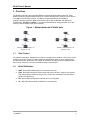
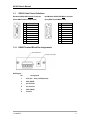
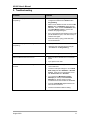
NL900
Industrial 900MHz
RS232 Radio Modem
User’s Manual
Version B0
2461 Impala Drive
Carlsbad, CA 92010
(760) 444-5995
www.rfneulink.com
www.raveon.com
[email protected]
Document Information
Copyright
Information
Copyright © 2013 RAVEON TECHNOLOGIES All rights reserved.
The information contained in this manual and the accompanying
software programs are copyrighted and all rights are reserved by
RAVEON TECHNOLOGIES. RAVEON TECHNOLOGIES reserves the right to make
periodic modifications of this product without obligation to notify
any person or entity of such revision. Copying, duplicating, selling, or otherwise
distributing any part of this product without the prior consent of an authorized
representative of RAVEON TECHNOLOGIES is prohibited.
All brands and product names in this publication are registered
trademarks or trademarks of their respective holders.
11/16/2004
2
This material is preliminary
Information furnished by RAVEON TECHNOLOGIES in this specification is believed to be
accurate. Devices sold by RAVEON TECHNOLOGIES are covered by the warranty and patent
indemnification provisions appearing in its Terms of Sale only. RAVEON TECHNOLOGIES
makes no warranty, express, statutory, and implied or by description, regarding the information
set forth herein. RAVEON TECHNOLOGIES reserves the right to change specifications at any
time and without notice.
RAVEON TECHNOLOGIES’s products are intended for use in normal commercial
applications. Applications requiring extended temperature range or unusual environmental
requirements such as military, medical life-support or life-sustaining equipment are specifically
not recommended without additional testing for such application.
CC Information
FCC Notice
WARNING: This device complies with Part 15 of the FCC Rules. Operation is subject to
the following two conditions: (1) This device may not cause harmful
interference and (2) This device must accept any interference received,
including interference that may cause undesired operation.
RF Exposure/Installation Instructions
WARNING: To satisfy FCC RF exposure requirements for mobile transmitting devices,
this equipment must be professionally installed such that the end user is
prevented from replacing the antenna with a non-approved antenna. The
end user should also be prevented from being within 20cm of the antenna
during normal use with the exception of hands, feet, wrists and ankles.
The preceding statement must be included as a CAUTION statement in
manuals for OEM products to alert users on FCC RF Exposure compliance.
Caution: Any change or modification not expressly approved by
RAVEON TECHNOLOGIES could void the user’s authority to operate
the equipment.
11/16/2004
3
Table of Contents
USER’S MANUAL ........................................................................................... 1
FIGURES.............................................................................................................................. 4
1.
OVERVIEW .............................................................................................................. 5
1.1
FLOW CONTROL................................................................................................... 5
1.2
NL900 DEFINITIONS ............................................................................................ 5
1.3
RS232 CABLE P INOUT DEFINITIONS .................................................................... 6
1.3.1
RS485 Terminal Block Pin Assignments..................................................... 6
1.4
NL900 CONFIGURATION UTILITY SOFTWARE ..................................................... 7
1.4.1
Installation .................................................................................................. 7
1.4.2
Software Definitions.................................................................................... 8
1.4.3
Programming ............................................................................................ 10
2.
TROUBLESHOOTING ......................................................................................... 11
Figures
Figure 1 - Multiple Networks Of NL900 Units .............................................................. 5
11/16/2004
4
NL900 User’s Manual
1. Overview
The NL900 product provides a wireless RS232 connection between different devices. Each
NL900 unit can be programmed as a Server or a Client, allowing for the creation of a two device
or multiple device wireless network. In addition, multiple networks can be created by
programming each network of NL900 units with a unique Channel Number and System ID
combinations. See Figure 1 below. To create a wireless network, simply program one of the
units as a Server and the other units as Clients.
Figure 1 - Multiple Networks Of NL900 Units
Example: Channel Number = 13
System ID = 123
1.1
Example: Channel Number = 25
System ID = 256
Flow Control
For optimal performance, Hardware Flow Control is strongly recommended. If the Clear To Send
(CTS) line is not used, there is a chance that the transmit buffer will fill up to its maximum limit
and data will be lost. Whenever CTS is High, the NL900 is not ready to receive additional data
from its host. When CTS is Low, the NL900 is ready to receive data.
1.2
NL900 Definitions
1. PWR: Green LED indicates power is connected to the unit.
2. LINK: Red LED indicates the Client unit(s) and Server unit are in range of one another.
Link LED remains activated on Server units. Client units activate the Link LED when in
range of the Server unit
3. RX: Green LED indicates when a NL900 unit is receiving data.
4. TX: Red LED indicates when a NL900 unit is sending data.
11/16/2004
5
NL900 User’s Manual
1.3
RS232 Cable Pinout Definitions
Standard RS232 DB9 Female Connector
Null Modem RS232 DB9 Male Connector
(Black DB9 Female/Female Cable)
(Gray DB9 Female/Male Cable)
Pin
1
2
3
4
5
6
7
8
9
Description
DCD
RxD
TxD
DTR
GND
DSR
RTS
CTS
RI
Pin
NC
2
3
4
5
6
7
8
NC
Description
DCD
TxD
RxD
DSR
GND
DTR
CTS
RTS
RI
1.3.1 RS485 Terminal Block Pin Assignments
Half Duplex:
Pin
11/16/2004
Assignment
1
VCC (6V – 18V) (1.3A Required)
2
485- (485B)
3
No Connect
4
No Connect
5
485+ (485A)
6
Ground
6
NL900 User’s Manual
1.4
NL900 Configuration Utility Software
The software CD included with your NL900 units provides a utility for changing the settings on
each unit. The software is compatible with Microsoft® Windows 95, 98, 2000, Me, NT and XP.
1.4.1 Installation
Follow the procedure below to install the NL900 Configuration Utility software.
1. Insert the CD into the desired CD-ROM drive on your computer.
2. The software should launch automatically. If not, use Windows Explorer and Double click
on the appropriate CD drive.
3. Click on Enter.
4. Select Software.
5. Click on version 1.0 for CL4490 NL900 .
6. When prompted, accept the default directory or change to the desired directory where the
program files will be installed.
7. When finished, a window will be displayed indicating a successful installation. Select OK.
11/16/2004
7
NL900 User’s Manual
1.4.2 Software Definitions
1.
Client/Server: Designates NL900 type. In each network, there must be only one Server.
All other NL900 units must be programmed as Clients. The number of Clients in the
network is not limited; however, if performance diminishes, consider additional RF
Networks.
2. Interface Baud Rate: This defines the serial baud rate between the NL900 unit and the
host device, such as a PC. The RF transmission rate is fixed. Default baud rate setting
is 57600 unless the units have been pre-configured by Raveon Technologies. The
Baud Rate setting of the NL900 must match the Baud Rate setting of its host
device.
3. Interface Timeout: This parameter specifies the amount of time between bytes that a
NL900 will wait before transmitting the data packet. This setting is automatically
calculated by the configuration software based on the Baud Rate setting, but can be
modified by the user for optimization purposes.
IMPORTANT NOTE: W hen configuring units with baud rates lower than 9600kbps it is
important that the Interface Timeout is not set to a value lower than 3. It is strongly
recommended that the default Interface Timeout be used. The default values are
automatically calculated based on the unit’s Baud Rate setting.
4. Channel Number: A number that designates an independent network of NL900 units.
Up to 32 independent networks can created. The valid range of values for this field is 16
to 47.
5. Maximum Transmit Attempts: This value represents the maximum number of times a
particular data packet can be sent by a NL900 unit. The default value is 16 attempts. If
communication is lost and the Client’s Link LED is on, try increasing this value in small
increments until communication is reestablished. This value is always associated to
Client radios and Server radios in Point to Point Mode. The valid range of values for this
field is 2 to 255.
11/16/2004
8
NL900 User’s Manual
6. Broadcast Attempts: For Point-to-Multipoint networks only. This value represents the
number of times a data packet will be sent by the Server NL900 unit. The default value is
4 attempts. If communication is lost and the Clients’ Link LED is on, try increasing this
value in small increments until communication is reestablished. The valid range of values
for this field is 2 to 255.
7. System Identification: A number from 0 to 256 that provides added security to each
independent network of NL900 units. The System ID is used in conjunction with the
Channel Number and serves as an RF password to maintain secure transfers of data.
The combination of the Channel Number and System ID must be unique to each network
of NL900 to establish communication. Multiple Servers in the same coverage area must
be programmed with different Channel Numbers to prevent inoperability of the networks.
The System ID will not prevent inoperability that occurs from locating multiple Servers
with the same Channel Number in the same coverage area.
8.
Important Note: Separate Collocated NL900 networks must operate on
different Channel Numbers. All units in a given NL900 network must have
identical Channel Numbers and System IDs.
9. Data Encryption Key: Encryption is the process of encoding an information bit stream
to secure the data content. The DES algorithm is a common, simple and well-established
encryption routine. An encryption key of 56 bits is used to encrypt the packet. The
receiver must use the exact same key to decrypt the packet; otherwise garbled data will
be produced.
10. Destination Address: The MAC Address of the opposite NL900 in a point to point
application. Used to optimize point to point communications by utilizing RF
Acknowledgement.
11. Data Encryption: Enables the Data Encryption Key. All NL900s in the same network
must have the same encryption setting.
12. RTS Enable: Enables the Request to Send control line. W hen enabled, RTS Low
equals data flow. RTS High equals hold off data.
13. Parity: Considered 9-Bit mode. Needs to be enabled if host requires even or odd parity
and 8 data bits.
14. Full Duplex: This mode restricts Client radios to transmitting on odd numbered
frequency hop bins and the Server to even numbered frequency hop bins. Though the
RF hardware is still technically half duplex, it makes the transceiver seem full duplex.
This can cause overall throughputs to be cut in half. Note: All transceivers on the
same network must have the same setting for Full Duplex.
15. Modem Mode: Enables DCD, DTR, DSR and Ring Indicator control lines.
16. Firmware Version: Displays the NL900’s firmware version.
17. MAC Address: A unique 6 Byte, IEEE 802.3 Ethernet address assigned by Raveon
Technologies to each NL900.
18. Port: Serial communications port connected to the NL900 unit.
19. Baud Rate: Must equal the Baud Rate setting of the NL900 unit that is about to be
programmed.
20. System Config: Type of NL900 network to be configured. Valid choices are Point-toPoint (one Server and one Client) or Point-to-Multipoint (one Server and multiple
Clients).
11/16/2004
9
NL900 User’s Manual
1.4.3 Programming
Programming is accomplished with the following procedure:
1. Connect a NL900 unit to a serial communications port on your computer.
2. Connect the power supply to the NL900 unit. Make sure the Pwr LED is on.
3. Start the NL900 Configuration Utility.
4. Select the COM Port that is connected to the NL900 unit.
5. Select the Baud Rate of the NL900 unit. All NL900 units are shipped with a default rate
of 57600 (unless units have been preconfigured to match specific serial settings). If the
Baud Rate of the NL900 unit is changed as described below in Section 1.4.5 Changing
NL900 Settings, then this setting must be set to the same Baud Rate to allow proper
programming of the units.
6. Select the System Configuration for the NL900 network, Point-to-Point (one Server and
one Client) or Point-to-Multipoint (one Server and multiple Clients).
7. Select Read Radio to display the current settings of the NL900 unit.
8. Change desired settings.
9. After all changes have been made, select Write Radio to save the changes.
10.
Cycle Power to the unit after all changes have been saved. This will set the
NL900 unit to its normal mode of operation.
August 2013
10
NL900 User’s Manual
2. Troubleshooting
Problem
Solution
Read Radio displays error message: “Radio not
responding.”
1.
Make sure the proper settings are set in the
Configuration Software. See Section 1.4.3
Programming.
2.
Make sure the NL900 unit does not have a Null
Modem cable. Null Modem cables will have
DB9 Male. If the unit has a Null Modem cable,
use a Null Modem adapter to connect the
NL900 to the programming PC.
3.
If any other programs that utilize the same COM
port as NL900s are open, close them and try to
read the radio again.
4.
Reset the radio by cycling power after each
unsuccessful Read.
Write Radio displays error message: “Radio not
responding.”
1.
Cycle power to the radio.
2.
Read the radio and make desired changes.
See Section 1.4.3 Programming.
Garbled Data received.
1.
Check Data Encryption Standard settings.
Client’s Link LED does not come on.
2.
Make sure Server NL900 unit is connected to
power.
3.
Cycle power to the radio.
1.
Make sure the NL900 unit(s) is connected to the
correct COM Port.
2.
Check the COM port settings for correct Baud
Rate, Parity and either Hardware or No Flow
Control. Units can have transmission errors
with Flow Control set to Xon/Xoff.
3.
Try increasing the Maximum Transmit
Attempts (for Clients) and/or Broadcast
Attempts (for Servers) values in small
increments until communication is established.
4.
Connect a Null Modem adapter between the
Client and its host device.
5.
Check the Destination Address setting.
Link LED is on, but data does not get transmitted or
received.
August 2013
11
NL900 User’s Manual
Limited One Year Warranty
If within one years from date of purchase, this product fails due to a defect in material or workmanship,
Raveon Technologies, Incorporated will repair or replace it, at Raveon’s sole discretion. This warranty
is extended to the original consumer purchaser only and is not transferable.
This warranty does not apply to:
(a) product damage caused by accident, dropping or abuse in handling, acts of God or any
negligent use;
(b) units which have been subject to unauthorized repair, opened, taken apart or otherwise
modified; (c) units not used in accordance with instructions;
(d) damages exceeding the cost of the product;
(e) batteries;
(f) the finish on any portion of the product, such as surface and/or weathering, as this is considered
normal wear and tear;
(g) transit damage, initial installation costs, removal costs, or reinstallation costs;
(h) damage due to lighting, floods, water intrusion, condensing humidity, fire, or earthquakes.
RAVEON TECHNOLOGIES INCORPORATED WILL NOT BE LIABLE FOR INCIDENTAL OR
CONSEQUENTIAL DAMAGES. SOME STATES DO NOT ALLOW THE EXCLUSION OR
LIMITATION OF INCIDENTAL OR CONSEQUENTIAL DAMAGES, SO THE ABOVE LIMITATION OR
EXCLUSION MAY NOT APPLY TO YOU. THIS WARRANTY IS IN LIEU OF ALL OTHER EXPRESS
OR IMPLIED WARRANTIES. ALL IMPLIED WARRANTIES, INCLUDING THE WARRANTY OF
MERCHANTABILITY AND THE WARRANTY OF FITNESS FOR A PARTICULAR PURPOSE, ARE
HEREBY MODIFIED TO EXIST ONLY AS CONTAINED IN THIS
LIMITED WARRANTY, AND SHALL BE OF THE SAME DURATION AS THE WARRANTY PERIOD
STATED ABOVE. SOME STATES DO NOT ALLOW LIMITATIONS ON THE DURATION OF AN
IMPLIED WARRANTY, SO THE ABOVE LIMITATION MAY NOT APPLY TO YOU.
This warranty gives you specific legal rights and you may also have other rights which vary from state
to state.
Warranty service is available by mailing postage prepaid to:
Raveon Technologies Corporation
2461 Impala Drive
Carlsbad, CA 92010 - USA
To obtain warranty service, include a copy of the original sales receipt or invoice showing the date, location, and
price of purchase include a written description of the problem with the product, a phone number and name of
person who may be contacted regarding the problem, and the address to where the product should be returned.
Products repaired under warranty will typically have their program memories erased and reset to factory default
settings.
August 2013
12