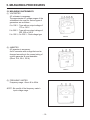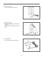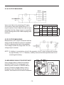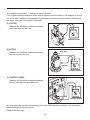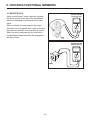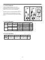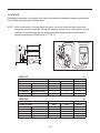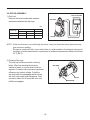
1
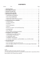
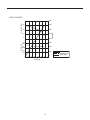
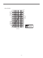
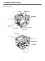
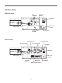
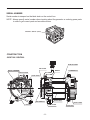
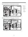
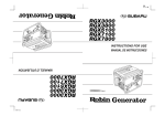
SERVICE
MANUAL
Models
RGX7100, 7800
GENERATORS
PUB-GS6828
Rev. 07/09
Robin America, Inc.
905 Telser Road • Lake Zurich, IL 60047 • Phone: 847-540-7300• Fax: 847-438-5012
e-mail: [email protected] • www.subarupower.com
© Copyright 2009 Robin America, Inc.
CONTENTS
Section
Title
Page
1. SPECIFICATIONS. . . . . . . . . . . . . . . . . . . . . . . . . . . . . . . . . . . . . . . . . . . . . . . . . . . . . . . . . . . 1
2. PERFORMANCE CURVES . . . . . . . . . . . . . . . . . . . . . . . . . . . . . . . . . . . . . . . . . . . . . . . . . . . . 2
3. GENERAL DESCRIPTION. . . . . . . . . . . . . . . . . . . . . . . . . . . . . . . . . . . . . . . . . . . . . . . . . . . . . 6
4. RANGE OF APPLICATIONS. . . . . . . . . . . . . . . . . . . . . . . . . . . . . . . . . . . . . . . . . . . . . . . . . . . 9
5. MEASURING PROCEDURES. . . . . . . . . . . . . . . . . . . . . . . . . . . . . . . . . . . . . . . . . . . . . . . . . 12
5-1 MEASURING INSTRUMENTS. . . . . . . . . . . . . . . . . . . . . . . . . . . . . . . . . . . . . . . . . . . . . . 12
5-2 AC OUTPUT MEASURING. . . . . . . . . . . . . . . . . . . . . . . . . . . . . . . . . . . . . . . . . . . . . . . . . 14
5-3 DC OUTPUT MEASURING . . . . . . . . . . . . . . . . . . . . . . . . . . . . . . . . . . . . . . . . . . . . . . . . 14
5-4 MEASURING INSULATION RESISTANCE. . . . . . . . . . . . . . . . . . . . . . . . . . . . . . . . . . . . 14
6. CHECKING FUNCTIONAL MEMBERS. . . . . . . . . . . . . . . . . . . . . . . . . . . . . . . . . . . . . . . . . . 16
6-1 RECEPTACLES. . . . . . . . . . . . . . . . . . . . . . . . . . . . . . . . . . . . . . . . . . . . . . . . . . . . . . . . . 16
6-2 CIRCUIT BREAKER. . . . . . . . . . . . . . . . . . . . . . . . . . . . . . . . . . . . . . . . . . . . . . . . . . . . . . 17
6-3 STATOR. . . . . . . . . . . . . . . . . . . . . . . . . . . . . . . . . . . . . . . . . . . . . . . . . . . . . . . . . . . . . . . 18
6-4 ROTOR ASSEMBLY. . . . . . . . . . . . . . . . . . . . . . . . . . . . . . . . . . . . . . . . . . . . . . . . . . . . . . 19
6-5 BRUSH. . . . . . . . . . . . . . . . . . . . . . . . . . . . . . . . . . . . . . . . . . . . . . . . . . . . . . . . . . . . . . . . 20
6-6 A.V.R. (AUTOMATIC VOLTAGE REGULATOR). . . . . . . . . . . . . . . . . . . . . . . . . . . . . . . . 20
6-7 DIODE STACK. . . . . . . . . . . . . . . . . . . . . . . . . . . . . . . . . . . . . . . . . . . . . . . . . . . . . . . . . . 22
6-8 OIL SENSOR . . . . . . . . . . . . . . . . . . . . . . . . . . . . . . . . . . . . . . . . . . . . . . . . . . . . . . . . . . . 23
6-9 IDLE CONTROL (OPTIONAL EQUIPMENT). . . . . . . . . . . . . . . . . . . . . . . . . . . . . . . . . . . . . . . 24
7. DISASSEMBLY AND ASSEMBLY . . . . . . . . . . . . . . . . . . . . . . . . . . . . . . . . . . . . . . . . . . . . . 27
7-1 PREPARATION and PRECAUTIONS . . . . . . . . . . . . . . . . . . . . . . . . . . . . . . . . . . . . . . . . 27
7-2 DISASSEMBLY PROCEDURES . . . . . . . . . . . . . . . . . . . . . . . . . . . . . . . . . . . . . . . . . . . . 27
7-3 COMPONENT PARTS. . . . . . . . . . . . . . . . . . . . . . . . . . . . . . . . . . . . . . . . . . . . . . . . . . . . 33
7-4 ASSEMBLY PROCEDURES . . . . . . . . . . . . . . . . . . . . . . . . . . . . . . . . . . . . . . . . . . . . . . . 37
7-5 CHECKING, DISASSEMBLY and REASSEMBLY of the CONTROL PANEL . . . . . . . . . . 48
8. TROUBLESHOOTING. . . . . . . . . . . . . . . . . . . . . . . . . . . . . . . . . . . . . . . . . . . . . . . . . . . . . . . 49
8-1 NO AC OUTPUT. . . . . . . . . . . . . . . . . . . . . . . . . . . . . . . . . . . . . . . . . . . . . . . . . . . . . . . . . 49
8-2 AC VOLTAGE IS TOO HIGH OR TOO LOW. . . . . . . . . . . . . . . . . . . . . . . . . . . . . . . . . . . 50
8-3 AC VOLTAGE IS NORMAL AT NO-LOAD, BUT THE LOAD CANNOT BE APPLIED. . . . 51
8-4 NO DC OUTPUT. . . . . . . . . . . . . . . . . . . . . . . . . . . . . . . . . . . . . . . . . . . . . . . . . . . . . . . . . 52
9. WIRING DIAGRAM . . . . . . . . . . . . . . . . . . . . . . . . . . . . . . . . . . . . . . . . . . . . . . . . . . . . . . . . . 53
NOTE
This Service Manual excludes information for engine.
As for the total servicing information as a generator set, please refer in conjunction with the
Robin EX35/40 OHC Engine Service Manual.
1. SPECIFICATIONS
MODEL
RGX7100
Type
RGX7800
Brush, self-exciting, 2-poles, single phase
Voltage regulating system
AVR type
AC Output
Rated voltage
Generator
Rated current
Rated output
V
A
VA (W)
50Hz
220, 240
60Hz
120 / 240
50Hz
20.9, 19.2
25, 22.9
60Hz
41.7 / 20.8
50 / 25
50Hz
4600
5500
60Hz
5000
6000
Rated power factor
1.0
Safety device type
Fuse-less circuit breaker
DC Output
Rated voltage
V
12
Rated current
A
8.3
Safety device type
Fuse-less circuit breaker
Model
EX35D
Type
Engine
Displacement
ROBIN, Air-cooled, 4-stroke, OHC, Gasoline Engine
mL
404
Fuel
Automotive Unleaded Gasoline
Fuel tank capacity
L
Engine oil capacity
L
22.0
(27.5)*1
1.2
Spark plug
BR-6HS (NGK)
Starting system
Electric starter / Recoil
Direction of rotation
Dimension
EX40D
Counter - clockwise
Length
mm
725 (975)*2
Width
mm
530
Height
mm
580
Dry weight
kg
86(96)*3
Specifications are subject to change without notice.
*1: ( ) shows the filled amount up to the "LEVEL" position.
*2: ( ) shows dimensions with Battery frame.
*3: ( ) shows dry weight with Electric starter.
-1-
88(98 )*3
2. PERFORMANCE CURVES
•RGX7100
50Hz-220V
N/A
50Hz-240V
N/A
-2-
60Hz-120/240V
Voltage (V)
62.5
7000
60
6000
57.5
5000
55
4000
250
[125]
3000
240
[120]
2000
230
[115]
1000
0
10
20
30
40
50
60
Current (A)
-3-
70
0
Output (VA)
Frequency (Hz)
8000
Voltage (V)
Frequency (Hz)
Output (VA)
•RGX7800
50Hz-220V
N/A
50Hz-240V
N/A
-4-
60Hz-120/240V
Voltage (V)
65
8000
62.5
7000
60
6000
57.5
5000
55
4000
250
[125]
3000
240
[120]
2000
230
[115]
1000
0
10
20
30
40
50
60
Current (A)
-5-
70
0
Output (VA)
Frequency (Hz)
9000
Voltage (V)
Frequency (Hz)
Output (VA)
3. GENERAL DESCRIPTION
RGX7100, RGX7800
Tank cap
Engine switch
Control panel
Fuel strainer
(Fuel valve)
Recoil starter
handle
Oil gauge (oil filler)
Recoil starter
Oil drain plug
Fuel gauge
Fuel tank
Choke lever
Spark plug cap
Air cleaner
Muffler
Muffler cover
-6-
CONTROL PANEL
(50Hz-220V, 240V)
AC
receptacle
AC circuit
breaker
Voltmeter
[Electric starter model]
V
Key switch
DC circuit
breaker
Engine switch
Earth (ground)
terminal
DC receptacle
(60Hz-120/240V)
AC receptacle 30A
AC receptacle 30A
Idle Control Switch
AC receptacle 20A
Pilot lamp
[Electric starter model]
AC circuit
breaker
Key switch
DC circuit
breaker
Engine switch
Full power
switch
Hour meter
Earth (ground) terminal
-7-
DC receptacle
SERIAL NUMBER
Serial number is stamped on the label stuck on the control box.
NOTE : Always specify serial number when inquiring about the generator or ordering spare parts
in order to get correct parts and accurate service.
PROD No. / SER No. (Label)
CONSTRUCTION
•RGX7100 / RGX7800
STATOR CORE
END COVER
EARTH TERMINAL
BRUTH
BRUSH HOLDER
FLANGE BOLT
DIODE STACK
ROTOR BOLT
AVR UNIT
STATOR BOLT
FRONT COVER
REAR COVER
-8-
N-BRACKET
4. RANGE OF APPLICATIONS
Generally, the power rating of an electrical appliance indicates the amount of work that can be
done by it. The electric power required for operating an electrical appliance is not always equal to
the output wattage of the appliance. The electrical appliances generally have a label showing their
rated voltage, frequency, and power consumption (input wattage). The power consumption of an
electrical appliance is the power necessary for using it. When using a generator for operating an
electrical appliance, the power factor and starting wattage must be taken into consideration.
In order to determine the right size generator, it is necessary to add the total wattage of all
appliances to be connected to the unit.
Refer to the followings to calculate the power consumption of each appliance or equipment by its
type.
(1) Incandescent lamp, heater, etc. with a power factor of 1.0
Total power consumption must be equal to or less than the rated output of the generator.
Example : A rated 3000W generator can turn thirty 100W incandescent lamps on.
(2) Fluorescent lamps, motor driven tools, light electrical appliances, etc. .
with a smaller power factor
Select a generator with a rated output equivalent to 1.2 to 2 times of the power consumption of
the load. Generally the starting wattage of motor driven tools and light electrical appliances are
1.2 to 3 times lager than their running wattage.
Example: A rated 250 W electric drill requires a 400 W generator to start it.
NOTE 1: If a power factor correction capacitor is not applied to the fluorescent lamp, the more
power shall be required to drive the lamps.
NOTE 2: Nominal wattage of the fluorscent lamp generally indicates the output wattage of the lamp.
Therefore, if the fluorescent lamp has no special indication as to the power consumption,
efficiency should be taken into account as explained in ltem (5) on the following page.
(3) Mercury lamps with a smaller power factor
Loads for mercury lamps require 2 to 3 times the indicated wattage during start-up.
Example : A 400 W mercury lamp requires 800 W to 1200 W power source to be turned on. A
rated 3000 W generator can power two or three 400 W mercury lamps.
(4) Initially loaded motor driven appliances such as water pumps, compressors, etc.
These appliances require large starting wattage which is 3 to 5 times of running wattage.
Example : A rated 900 W compressor requires a 4500 W generator to drive it.
NOTE 1: Motor-driven appliances require the aforementioned generator output only at the
starting. Once their motors are started, the appliances consume about 1.2 to 2 times
their rated power consumption so that the excess power generated by the generator
can be used for other electrical appliances.
NOTE 2 : Motor-driven appliances mentioned in items (3) and (4) vary in their required motor
starting power depending on the kind of motor and start-up load. If it is difficult to
determine the optimum generator capacity, select a generator with a larger capacity.
-9-
(5) Appliances without any indication as to power consumption
Some appliances have no indication as to power consumption; but instead the work load
(output) is indicated. In such a case, power consumption is to be worked out according to the
numerical formula mentioned below.
(Output of electrical appliance)
= (Power consumption)
(Efficiency)
Efficiencies of some electrical appliances are as follows :
Single-phase motor . . . 0.6 to 0.75
Fluorescent lamp . . . . . 0.7 to 0.8
(
The smaller the motor, the
lower the efficiency.
)
Example 1 : A 40W fluorescent lamp means that its luminous output is 40W. Its efficiency is 0.7
and accordingly, power consumption will be 40÷0.7= 57W. As explained in Item (2),
multiply this power consumption value of 57 W by 1.2 to 2 and you will get the figure
of the necessary capacity of a generator. In other words, a generator with a rated
output of 1000W capacity can light nine to fourteen 40 W fluorescent lamps.
Example 2 : Generally speaking, a 400 W motor means that its work load is 400 W. Efficiency of
this motor is 0.7 and power consumption will be 400÷0.7= 570 W. When this motor is
used for a motor-driven tool, the capacity of the generator should be multiple of 570
W by 1.2 to 3 as explained in the ltem (3). 570 (W) × 1.2 to 3 = 684 (W) to 1710 (W)
Applicable Wattage(approx. W)
Applications
50Hz
60Hz
RGX7100
RGX7800
RGX7100
RGX7800
Incandescent lamp, Heater
4600
5500
5000
6000
Fluorescent lamp, Electric tool
2550
3000
2750
3300
Mercury lamp
1850
2200
2000
2400
Pump, Compressor
1150
1350
1250
1500
Table. 4-1
- 10 -
NOTES : Wiring between generator and electrical appliances
1. Allowable current of cable
Use a cable with an allowable current that is higher than the rated input current of the load
(electrical appliance). If the input current is higher than the allowable current of the cable
used, the cable will become excessively heated and deteriorate the insulation, possibly
burning it out. Table 4-2 shows cables and their allowable currents for your reference.
2.Cable length
If a long cable is used, a voltage drop occurs due to the increased resistance in the
conductors decreasing the input voltage to the load (electrical product). As a result, the load
can be damaged. Table 4-2 shows voltage drops per 100 meters of cable.
Allowable No.of strands.
Resistance
current / strands dia.
Current Amp.
mm2
No.
A
No./mm
Ω/100m
1A
0.75
18
7
30/0.18
2.477
2.5V
7.5V 12.5V
1.25
16
12
50/0.16
1.486
1.5V
4.5V
2.0
14
17
37/0.26
0.952
1V
3.5
12 to 10
23
45/0.32
0.517
5.5
10 to 8
35
70/0.32
0.332
3A
5A
8A
10A
12A
15A
-
-
-
-
7.5V
12V
15V
18V
-
3V
5V
8V
10V
12V
15V
-
1.5V
2.5V
4V
5V
6.5V
7.5V
-
1V
2V
2.5V
3.5V
4V
5V
Table. 4-2
Voltage drop indicates as V= 1 × R × I × L
100
Rmeans resistance (Ω/100 m) on the above table.
I means electric current through the wire (A).
L means the length of the wire (m).
The length of wire indicates round length, it means twice the length from generator to
electrical tools.
- 11 -
Voltage drop
Nominal .
cross . A.W.G.
section
5. MEASURING PROCEDURES
5-1 MEASURING INSTRUMENTS
(1) VOLTMETER
AC voltmeter is necessary.
The approximate AC voltage ranges of the
voltmeters to be used for various types of
generators are as follows :
0 to 150 V : Type with an output voltage of
110 or 120 V
0 to 300 V : Type with an output voltage of
220, 230 or 240 V
0 to 150 V, 0 to 330 V : Dual voltage type
FOR AC
(2) A
MMETER
AC ammeter is necessary.
An AC ammeter with a range that can be
changed according to the current rating of
a given generator is most desirable.
(About 10 A, 20 A, 100 A)
FOR AC
(3) F
REQUENCY METER
Frequency range : About 45 to 65Hz
NOTE : Be careful of the frequency meter's
input voltage range.
- 12 -
(4) C
IRCUIT TESTER
Used for measuring resistance, etc.
(5) M
EGGER TESTER
Used for measuring generator insulation
resistance.
Select one with testing voltage range of
500V.
(6) T
ACHOMETER
Use the contactless type tacho meter.
- 13 -
5-2 AC OUTPUT MEASURING
SWITCH
LOAD
A
~
F
V
~
Use a circuit above for measuring AC output.
A hot plate or lamp with a power factor of 1.0
may be used as a load. Adjust the load and rpm.
and check that the voltage range is as specified
in the following table at the rated amperage and
rated rpm.
Model
RGX7100
RGX7800
Hz
Rated voltage
120V
220V
240V
50
-
219 - 228
239 - 248
60
118 - 127
219 - 228
239 - 248
50
-
219 - 228
239 - 248
60
118 - 127
219 - 228
239 - 248
Voltage range
TO AC RECEPTACLE
5-3 DC OUTPUT MEASURING
Measurement of DC output is executed with the
switch turned ON while the current is regulated
at 8.3A by adjusting the load to the generator.
If the voltage is within the range from 10V, the
voltage output is normal.
NOTE : If a battery is connected as a load to the generator, the DC output voltage will increase
by approximately 1 to 2 V. Therefore, carefully observe the electrolyte level and do not
overcharge the battery.
5-4 MEASURING INSULATION RESISTANCE
Use a megger tester to check the insulation
resistance. Remove the control panel, and
disconnect the connector of GREEN lead for
ground. Connect a megger tester to one of
receptacle output terminals and the ground
terminal, then measure the insulation resistance.
MEGGER TESTER
- 14 -
An insulation resistance of 1 megohm or more is normal.
(The original insulation resistance at the time of shipment from the factory is 10 megohm or more.)
If it is less than 1 megohm, disassemble the generator and measure the insulation resistance of
the stator, rotor and control panel individually.
(1) STATOR
Measure the insulation resistance between
each lead wire and the core.
MEGGER TESTER
(2) ROTOR
Measure the insulation resistance between
the slip ring and the core.
SLIP RING
ROTOR
MEGGER TESTER
(3) CONTROL PANEL
Measure the insulation resistance between
the live parts and the grounded parts.
MEGGER TESTER
Any part where the insulation resistance is less than 1MΩ has faulty insulation, and may cause
electric leakage and electric shock.
Replace the faulty part.
- 15 -
6. CHECKING FUNCTIONAL MEMBERS
6-1 RECEPTACLES
Using a circuit tester, check continuity between
the two terminals at the rear of the receptacles
while the receptacle is mounted on the control
panel.
When continuity is found between the output
terminals of the receptacle with a wire connected
across these terminals, the receptacle is normal.
When the wire is removed and no continuity is
found between these terminals, the receptacles
are also normal.
CIRCUIT TESTER
(Continuity test)
CIRCUIT TESTER
(Continuity test)
WIRE
- 16 -
6-2 CIRCUIT BREAKER
Check continuity between each of two
terminals at the rear of the circuit breaker
while it is mounted on the control panel.
PUSH type
REVER type
A
A
Normally, there is continuity between each of
the two when the circuit breaker is on while
there is no continuity when the circuit breaker
is off.
Type 1
Type 3
B
B
•AC CIRCUIT BREAKER
Model
RGX7100
RGX7800
Frequency
Rated output
50Hz
4600VA
60Hz
5000VA
50Hz
5500VA
60Hz
6000VA
Rated voltage
Rated fault current
220V
20
1
240V
N/A
1
120/240V
23
3
220V
N/A
1
240V
N/A
1
120/240V
28
3
•DC CIRCUIT BREAKER
Model
RGX7100
RGX7800
Type
Rated current
Rated voltage
Rated fault current
Type
8.3A
12V
10A
1
- 17 -
CIRCUIT TESTER
(Continuity test)
6-3 STATOR
Disengage connectors on the wires from stator and check the resistance between wires with a
circuit tester referring to the following table.
NOTE : If the circuit tester is not sufficiently accurate, it may not show the values given and
may give erroneous readings. Erroneous readings will also occur when there is a wide
variation of resistance among coil windings or when measurement is performed at
ambient temperatures different from 20 °C (68 °F).
AC
winding 1
Grn
W
Sub coil
Blu
Grn W Blu
Gry
Org
AC
winding 2
R
Blu
Grn
Blu
Blu
AVR unit
DC winding
W
CIRCUIT TESTER
(Resistance)
R
Brn
Bridge
diode
Brn
W
Blk
•RGX7100
(Ω)
FREQUENCY
50Hz
RATED VOLTAGE
60Hz
220V
240V
120/240V
AC WINDING 1
RED - GRAY
0.56
0.69
0.60
AC WINDING 2
ORANGE - BLUE
0.56
0.69
0.60
SUB COIL
BLUE - BLUE
1.64
1.74
1.53
DC WINDING
BROWN - BROWN
0.12
0.13
0.10
AC WINDING 1
GREEN - WHITE
0.10
0.12
0.10
•RGX7800
(Ω)
FREQUENCY
50Hz
RATED VOLTAGE
60Hz
220V
240V
120/240V
AC WINDING 1
RED - GRAY
0.59
0.64
0.41
AC WINDING 2
ORANGE - BLUE
0.59
0.64
0.41
SUB COIL
BLUE - BLUE
1.80
1.76
1.35
DC WINDING
BROWN - BROWN
0.13
0.10
0.09
AC WINDING 1
GREEN - WHITE
0.10
0.11
0.07
- 18 -
6-4 ROTOR ASSEMBLY
1) Field coil
Remove the brush holder and measure
resistance between the slip rings.
CIRCUIT TESTER
(Resistance)
SLIP RING
(Ω)
50Hz
Rotor.
(Slip ring)
220V
240V
60Hz
120/240V
RGX7100
49.0
49.0
49.0
RGX7800
55.0
55.0
55.0
ROTOR
NOTE : If the circuit tester is not sufficiently accurate, it may not show the values given and may
give erroneous readings.
Erroneous reading will also occur when there is a wide variation of resistance among coil
windings or when measurement is performed at ambient temperatures different from from
20°C (68°F).
2) Cleaning Slip rings
The slip ring surfaces must be uniformly
bright. Slip rings showing black spots,
excessive wear, or uneven wear must be
repaired. A stained slip ring lowers generator
efficiency and output voltage. Polish the
slip rings with fine sandpaper while turning
the rotor until rough spots disappear. Care
should be taken not to touch the rotor coils
with the sandpaper.
- 19 -
SLIP RING
ROTOR
SANDPAPER
6-5 BRUSH
The brushes must be smooth where they
contact the slip rings. If not, polish smooth the
brushes with sandpaper. A brush that is not
smooth produces arcs between the brush and
slip ring leading to possible damage. Usable
brush lengths are from 5 mm to 11 mm (0.20 "
to 0.43").
A brush shorter than 5 mm must be replaced
because decreased contact pressure between
the brush and slip ring lowers generator
efficiency and output voltage.
BRUSH
HOLDER
BRUSH
6-6 A.V.R. .
(AUTOMATIC VOLTAGE REGULATOR)
1) Features
This A.V.R. operates to control the field
current in order to maintain the output
voltage for the AC current, which generated
by the magnetic flux by the field coil.
5 mm
CIRCUIT TESTER
(Resistance)
2) A
.V.R. trouble may be identified by simply
looking at the A.V.R., or by the inter-lead
resistance with a tester, or actually mounting
it in the generator and operating it.
(a) A
.V.R. TROUBLE IDENTIFICATION by APPEARANCE
If an A.V.R. electronic part is burnt dark, or the surface epoxy resin melted, it often indicates
A.V.R. trouble.
(b) IDENTIFYING A.V.R. TROUBLE by CHECKING INTER-LEAD RESISTANCE
Check the inter-lead resistance of the A.V.R. with a tester, referring to the following table.
If the tester readings very greatly from the values specified in the table on next page, the
A.V.R. is faulty.
NOTE : Take tester inaccuracy into account in reading the tester.
- 20 -
(c) IDENTIFYING A.V.R. TROUBLE by
MOUNTING and OPERATING in THE
GENERATOR
ⓐⓑ
SCR or transistor damage cannot be
detected by simply looking at the A.V.R. or
checking the lead resistance.
Check it by mounting the suspectedly faulty
A.V.R. in a normal generator, or mount a
mormal A.V.R. in a generator which fails to
generate voltage.
①
② ③
④
ⓐ White
ⓑ Red
① Green
AVR unit
② White
③ Blue
④ Blue
* Checking table for analogue circuit tester.
RGX7100 / RGX7800
(Ω) (R±20%)
Apply black ⊖ needle of the circuit tester
White ⓐ
Red ⓑ
Green ①
White ②
Blue ③
Blue ④
-
2.1M
5.0M
5.1M
4.6M
4.2M
Red ⓑ
1.8M
-
2.1M
2.1M
1.9M
1.6M
Green ①
4.4M
2.0M
-
4.9M
4.4M
4.1M
White ②
4.6M
2.1M
5.1M
-
4.6M
4.2M
Blue ③
4.0M
1.7M
4.5M
4.5M
-
3.8M
Blue ④
4.2M
1.8M
4.7M
4.7M
4.2M
-
White ⓐ
Apply red ⊕ needle
of the circuit tester
- 21 -
6-7 DIODE STACK
CIRCUIT TESTER
(Continuity test)
Brown
Black
White
White
Brown
DIODE STACK
Black
Brown
Brown
Fig.6-8a
Fig.6-8b
Circuit inside of the diode stack is as shown in Fig.6-8a.
Check continuity between each terminal by using a circuit tester as shown in Fig.6-8b.
The diode stack is normal when continuity is as follows:
* Checking table for analogue circuit tester.
Analogue circuit tester
Apply red ⊕ needle
of the circuit tester
Apply black ⊖ needle of the circuit tester
Brown
Brown
White
Black
Brown
-
No continuity
Continuity
No continuity
Brown
No continuity
-
Continuity
No continuity
White
No continuity
No continuity
-
No continuity
Black
Continuity
Continuity
Continuity
-
* Checking table for digital circuit tester.
Apply red ⊕ needle of the circuit tester
Digital circuit tester
Apply black ⊖ needle
of the circuit tester
Brown
Brown
White
Black
Brown
-
No continuity
Continuity
No continuity
Brown
No continuity
-
Continuity
No continuity
White
No continuity
No continuity
-
No continuity
Black
Continuity
Continuity
Continuity
-
NOTE 1 : In checking the diode , direction of connection is contrary to the ordinary case because
of characteristics of the diode and battery incorporated in the tester.
NOTE 2 : "Continuity" means forward direction characteristics of the diode, and different from
short circuit condition (In which a pointer of the tester goes out of its normal scale),
shows resistance to some extent. When results of the checking indicates failure even in
one section, replace with a new one.
- 22 -
6-8 OIL SENSOR
(1) D
isconnect wires comming from the sensor at the connection.
(2) L
oosen the sensor to remove it from the engine.
(3) P
lug the opening of oil filler hole (created after sensor is removed) with suitable means such
as oil gauge.
(4) C
onnect the removed wires again with the oil sensor.
(5) S
tart the engine with the oil sensor removed and confirm if ;
a. Engine stops after 5 seconds which is normal, or
b. Engine does not stop after more than 10 seconds which is unusual.
NOTE : The sensor will not operate properly when wire is broken or poorly connected. Check the wires for correct connection. If it fails to stop within 5 seconds after the wirings
have checked, the sensor is wrong. Replace the sensor with new one.
6-8-1 SPECIFICATIONS
Type
Float type
(with lead switch incorporated)
Resistance .
(at FULL oil level)
100 M ohms or over
Operating Temperature
-30 to +180 degree Celsius
OIL SENSOR
6-8-2 CONSTRUCTION AND OPERATION
Disconnect wires comming from the sensor The
oil sensor is composed of the float, permanent
magnet incorporated into the float and the oil
sensor.
In accordance with the oil level, the float moves
up and down.
When the oil level is upper level, the float
moves up.
FLOAT
PERMANENT MAGNET
LEAD SWITCH
When the oil level is lower level, the float
moves down.
The permanent magnet is close to the lead
switch, and the lead switch is activated by the
magnetic force.
NOTE : With regards to the wiring diagram,
please refer to the section 9 (page46).
- 23 -
MAGNETIC FORCE
6-9 IDLE CONTROL (OPTIONAL EQUIPMENT)
(1) ENGINE SPEED IS NOT INCREASED
WHEN A LOAD IS APPLIED
1) Check the wattage of load applied to the
generator. If the generator is loaded over
the rated wattage, the engine speed can
not be increased. Most induction loads such
as electric motor or electric tools or welding
machine require three to five times large
wattage of their ratings at starting. This
starting wattage must not exceed the rated
output of the generator.
2) Check the slow set r.p.m.
The normal idling speed by the IDLE
CONTROL is as follows :
RGX7100/7800 (USA model) . . . 2100 to 2500 r.p.m.
The above speed setting is for cold
engine condition. If the engine speed is
out of adjusting range, move the solenoid
backward.
- 24 -
3) C
heck the wiring through ZCT on the IDLE
CONTROL UNIT.
IDEL CONTROL UNIT
Make sure that an output wire from main
coil is passing through the ZCT on the IDLE
CONTROL UNIT.
OUTPUT WIRE
ZCT
4) C
hecking the IDLE CONTROL UNIT Check
the resistance between five leads of IDLE
CONTROL UNIT with circuit tester.
5
1
CIRCUIT TESTER
(Resistance)
4
2
3
Terminal number of
the IDEL CONTROL UNIT
Apply black ⊖ needle of the circuit tester
Circuit tester .
(with battery power source 1.5 V)
Apply red ⊕ needle
of the circuit tester
①
②
③
④
⑤
①
-
∞
250kΩ
250kΩ
75kΩ
②
∞
-
∞
∞
∞
③
250kΩ
∞
-
250kΩ
75kΩ
④
250kΩ
∞
250kΩ
-
75kΩ
⑤
8.5kΩ
∞
7.8kΩ
7.8kΩ
-
NOTE : The resistance readings vary depending on the types of circuit testers. The above
table shows an example of the resistance readings measured by an ordina,y analogue
circuit tester with I . 5 volt battery power source. It is advisable for you to check the
resistance readings using your standard circuit tester and revise the checking table.
- 25 -
(2) ENGINE SPEED IS NOT REDUCED .
WHEN LOAD IS OFF
1) Check the wiring of SOLENOID.
Check two leads from SOLENOID are
securely connected.
2) Check the wiring of IDLE CONTROL UNIT.
Check all leads from IDLE CONTROL UNIT
are securely and correctly connected.
3) C
hecking the SOLENOID.
Measure the resistance between two leads
from SOLENOID.
Normal Resistance (Ω)
SOLENOID
25 - 31
If the resistance is larger or smaller than this
range, SOLENOID is defective,
Replace with a new one.
- 26 -
7. DISASSEMBLY AND ASSEMBLY
7-1 PREPARATION and PRECAUTIONS
(1) B
e sure to memorize the location of individual parts when disassembling the generator so that
the generator can be reassembled correctly. Tag the disassembled part with the necessary
information to facilitate easier and smoother reassembly.
(2) F
or more convenience, divide the parts into several groups and store them in boxes.
(3) T
o prevent bolts and nuts from being misplaced or installed incorrectly, replace them
temporarily to their original position.
(4) H
andle disassembled parts with care; clean them before reassembly using a neutral cleaning fluid.
(5) R
emove the battery before disassembling the generator. (Electric start models)
(6) Use all disassembly/assembly tools properly, and use the proper tool for each specific job.
(7) B
e sure to attach the foam rubber linings inside the covers on their original position when
reassembling the generator. When deformation or damage or falling-off of foam rubber lining
is found, replace it with new part. Failure to do so will result in poor performance and durability
of the generator.
(8) B
ind the wires and fuel pipes using wire bands as they have been done in original configuration.
NOTE : As to detailed information for servicing procedures on engine portion, please refer to
Robin engine service manual for "EX35/40".
7-2 DISASSEMBLY PROCEDURES
7-2-1 FUEL TANK
(1) S
hut the fuel strainer and discharge fuel
from caburetor.
FUEL TANK
FLANGE
BOLT
RUBBER
(TANK)
(2) Disconnect rubber pipe from the strainer.
(3) R
emove the fuel tank.
M6 flange bolt . . . 4 pcs.
Rubber(tank) . . . 4 pcs.
- 27 -
7-2-2 CONTROL PANEL and CONTROL BOX
(1) R
emove the control panel.
M6 flange bolt . . . 4 pcs.
M4 flange bolt . . . 4 pcs.
CONTROL BOX
(2) D
isconnect the connectors on the wiring
from the control panel to the alternator.
(3) R
emove the control box.
CONTROL PANEL
CONTROL PANEL
M4
M6
7-2-3 MUFFLER
(1) R
emove the Muffler Cover (R).
M6 flange bolt . . . 11 pcs.
MUFFLER COVER (R)
(2) L
oose the bolt for Muffler Cover (F).
M6 flange bolt . . . 2 pcs.
NOTE : Do not remove the flange bolt at this
process.
MUFFLER
COVER (F)
- 28 -
(3) R
emove the Muffler Bracket 2 from Muffler
Bracket 1.
M8 flange bolt . . . 2 pcs.
(4) L
oosen Nut and Washer for Exhaust Pipe.
Remove the Muffler from Cylinder Head.
MUFFLER
M8 nut and washer . . . 2
pcs. (Exhaust Pipe)
(5) R
emove the Muffler Cover (F).
M6 flange bolt . . . 2 pcs.
MUFFLER
COVER (F)
(6) R
emove the Muffler Bracket 1 from Rear
Cover.
M8 flange bolt . . . 1 pc. (Bracket)
M10 flange nut . . . 1 pc. (with Rear Cover)
MUFFLER
BRACKET 1
(7) R
emove the Guide plate and the Bracket
(Tank A) from frame.
BRACKET
(TANK A)
M6 flange bolt . . . 4 pcs. (Guide plate)
M6 flange bolt . . . 4 pcs. (Bracket / Tank A)
GUIDE PLATE
- 29 -
7-2-4 ALTERNATOR
(1) R
emove the end cover.
M6 flange bolt . . . 2 pcs.
Disconnect the
connectors
END COVER
FLANGE
BOLT
(2) D
isconnect the connectors on the wiring
from the alternator.
EARTH (GROUND) WIRE
DIODE
STACK
(3) R
emove the AVR unit, brush holder and
diode stack.
BRUSH
HOLDER
EARTH (GROUND) WIRE
(4) S
et the generator set with the rear cover
upwards.
REAR
COVER
AVR UNIT
MOUNT
RUBBER
NOTE : Before starting this work, make sure
engine oil has been discharged.
(5) R
emove the flange nut fixing rear cover
onto the mount base with mount rubber.
M10 flange nut . . . 1 pc.
FLANGE NUT
*Opposite side flange nut has been removed
at muffler disassembly process.
- 30 -
(6) R
emove the rear cover.
RGX7100 M6 × 180mm . . . 4 pcs.
RGX7800 M6 × 195mm . . . 4 pcs.
(7) T
ake out stator cover with crows (2 pcs)
raised up by using screw driver.
(8) Remove the stator.
NOTE : The stator is heavy. Be careful do not
hit the coil of the stator to the rotor.
STATOR COVER
(9) Take off the through bolt of the rotor.
(10) Use a bolt and oil as a tool for pulling out
rotor in the following procedures :
1. Pour engine oil into the center hole of
rotor shaft. Fill with oil to the shaft end.
2. Prepare a bolt with the following thread
size : M12 × 1.75 (RGX7100 / RGX7800)
- 31 -
3. Apply a few turns of seal tape around the
tip of the bolt.
SEAL TAPE
SEAL TAPE
4. Screw the bolt into the thread of the rotor
shaft.
5. Torque the bolt using a socket wrench
until the rotor comes off loose.
* The hydraulic pressure inside the rotor
shaft takes apart the rotor from the engine
shaft.
(11) Remove the front cover.
M8 × 20 bolt(countersunk head) . . . 4 pcs.
- 32 -
FRONT COVER
7-3 COMPONENT PARTS
(1)Generator assembly
RGX7100 / RGX7800
24.0-26.0 N-m
240-260 kgf-cm
17.7-19.2 ft-lbs
16.5-20.5 N-m
165-205 kgf-cm
12.2-15.2 ft-lbs
43.0-47.0 N-m
430-470 kgf-cm
31.7-34.7 ft-lbs
THROUGH BOLT
BOLT
BOLT
ROTOR
FRONT COVER
STATOR COVER
N-BRACKET
FAN
BEARING
STATOR
REAR COVER
DIODE STACK
BRUSH
HOLDER
FLANGE NUT
SPONGE (FILTER)
24.0-30.0 N-m
240-300 kgf-cm
17.8-22.2 ft-lbs
COVER
BOLT
END COVER
6.5-8.5 N-m
65-85 kgf-cm
4.8-6.3 ft-lbs
MOUNT RUBBER
AVR UNIT
- 33 -
(2) Control Box Assy
CONTROL BOX
CONTROL PANEL
ENGINE SWITCH
AC RECEPTACLE
KEY SWITCH
AC CIRCUIT
BREAKER
FULL POWER
SWITCH
EARTH (GROUND)
TERMINAL
HOUR METER
DC CIRCUIT
BREAKER
DC RECEPTACLE
- 34 -
IDEL CONTROL UNIT
(3) Fuel Tank
FUEL TANK CAP
FUEL GAUGE
FUEL FILTER
FUEL
STRAINER
FUEL TANK
FILTER
PACKING
CUP
BRACKET(TANK-A)
RUBBER PIPE
M6 × 16 BOLT
- 35 -
(4) Muffler
M6 × 12 flange bolt
M8 flange bolt
MUFFLER
BRACKET
12.0-15.0 N-m
120-150 kgf-cm
8.9-11.1 ft-lbs
M8 flange nuts
DUCT (CASE)
M8 flange bolt
A
18.0-22.0 N-m
180-220 kgf-cm
13.3-16.2 ft-lbs
23.0-30.0 N-m
230-300 kgf-cm
17.0-22.2 ft-lbs
M8 flange nuts
12.0-15.0 N-m
120-150 kgf-cm
8.9-11.1 ft-lbs
6.5-8.5 N-m
65-85 kgf-cm
4.8-6.3 ft-lbs
M8 flange nuts
EX. PIPE
18.0-22.0 N-m
180-220 kgf-cm
13.3-16.2 ft-lbs
EX. PIPE
12.0-15.0 N-m
120-150 kgf-cm
8.9-11.1 ft-lbs
M8 flange nuts
MUFFLER
BRACKET 1
A
18.0-22.0 N-m
180-220 kgf-cm
13.3-16.2 ft-lbs
M8 flange bolt
MUFFLER
5-6.5 N-m
50-65 kgf-cm
3.7-4.8 ft-lbs
GUIDE PLATE
6.5-8.5 N-m
65-85 kgf-cm
4.8-6.3 ft-lbs
MUFFLER
COVER (R)
MUFFLER
COVER (F)
MUFFLER COVER (R)
- 36 -
7-4 ASSEMBLY PROCEDURES
7-4-1 ENGINE and FRAME
(1) A
ttach the mount rubbers to the frame.
Insert the setting tongue of mount rubber
into the hole on the frame and tighten the
nut from the bottom of the frame.
FRAME UPPER
M8 flange nut . . . 4 pcs.
Tightening torque : 20.0-24.0 N•m.
200-240 kgf•cm.
(14.8-17.8ft•lbs)
NOTE : There are two type of mount rubber.
Before attaching the mount rubbers,
make sure the position.
①
③
Alternator side
Mount rubber (M10 × 40 bolt) : place ①,②
Mount rubber (M10 × 20 bolt) : place ③,④
FRAME
Engine side
②
(2) T
emporally attach the Mount Base to the
engine by inserting flange bolt into middle
hole on mount base and engine base.
Temporally fix the bolt by nut.
④
MOUNT BASE
NOTE : Meet other side hole on the mount
base with hole of engine base. (Refer
to right side picture)
ENGINE
M10 flange nut &
M10 × 40 flange bolt . . . 1 pc.
- 37 -
(3) Install the engine into the frame from the
side of it. Insert the bolt of mount rubbers
into the hole on the mount base. Tighten the
nuts over the mount rubber bolts to fix.
M10 flange nut . . . 2 pcs.
ENGINE
Tightening torque : 24.0-30.0 N•m.
240-300 kgf•cm.
(17.8-22.2ft•lbs)
Tighten the temporally fixed bolt and nut for mount base.
M10 flange nut & M10 × 40 flange bolt . . . 1 pc.
Tightening torque : 24.0-30.0 N•m.
240-300 kgf•cm.
(17.8-22.2ft•lbs)
NOTE : When tightening the nuts, slightly lift the engine so that the weight is not applied to the
mount rubbers.
7-4-2 FRONT COVER
(1) A
ttach the N-bracket onto the front cover.
BOLT
NOTE : Match the rib direction on the N-bracket
with the top mark on the front cover
surface.
M8 × 20 flange bolt . . . 4 pcs.
BOLT
N-BRACKET
FRONT
COVER
A
Tightening torque : 16.5-20.5 N•m.
165-205 kgf•cm.
(12.2-15.2ft•lbs)
TOP mark
RIB
View A
- 38 -
(2) A
ttach the front cover to the engine main
bearing cover.
TOP mark
NOTE : Match the top mark on the front cover
surface with upside direction.
M8 × 20 bolt(countersunk head) . . . 4 pcs.
Tightening torque : 24.0-26.0 N•m.
240-260 kgf•cm.
(17.8-19.2ft•lbs)
7-4-3 ROTOR
(1) Wipe off oil, grease and dust from the
tapered portion of engine shaft and
matching tapered hole of rotor shaft.
FAN
ROTOR
(2) Mount the rotor to the engine shaft.
Tighten the through bolt.
THROUGH BOLT
M10 × 285 flange bolt . . . 1 pc.(RGX7100)
M10 × 300 flange bolt . . . 1 pc.(RGX7800)
BEARING
Tightening torque : 43.0-47.0 N•m.
430-470 kgf•cm.
(31.8-34.8ft•lbs)
7-4-4 STATOR
(1) Put the stator in the front cover.
STATOR
FRONT
COVER
- 39 -
7-4-5 REAR COVER
(1)Put the rear cover over the rotor.
Pull out the stator wirings through the
opening of the rear cover.
REAR COVER
NOTE : Be careful not to give cuts to wires
when pulling them out from the rear
cover.
PLASTIC
HAMMER
(2)Tap on the rear cover evenly with a plastic
hammer to press the rotor bearing into the
rear cover.
(3) Fix the rear cover with bolts.
NOTE : Tighten the bolts evenly and in turns.
M6 × 180 flange bolt . . . 4 pcs.
Tightening torque : 6.5-8.5
65-85
(4.8-6.3
N•m.
kgf•cm.
ft•lbs)
REAR COVER
(4) T
emporally attached the Muffler Bracket 1
to the Rear Cover.
M8 × 16 flange bolt . . . 1 pc.
MUFFLER
BRACKET 1
(5) T
emporally assemble the Mount Base to
the Rear Cover by inserting flange bolt into
middle hole on Mount Base, Rear Cover
hole and Muffler Bracket 1 hole.
Temporally fix the bolt by nut.
MOUNT BASE
NOTE : Meet other side hole on the Mount
Base with hole of Rear Cover. (Refer to right side picture)
M10 flange nut &
M10 × 40 flange bolt . . . 1 pc.
- 40 -
(6) S
et the Mount Rubber bolts into the Mount
Base holes.
Don’t tighten the nut at this moment.
REAR COVER
MOUNT RUBBER
FLANGE NUT
(7) Install the brush holder, AVR unit and diode
stack in the rear cover.
M5 × 16 bolt . . . 2 pcs. (AVR unit)
Tightening torque : 4.0-4.5
40-45
(3.0-3.3
N•m.
kgf•cm.
ft•lbs)
BRUSH
HOLDER
AVR UNIT
DIODE
STACK
M5 × 16 bolt . . . 2 pcs. (brush holder)
M4 × 18 bolt . . . 1 pc. (diode stack)
Tightening torque : 1.5-2.0
15-20
(1.1-1.5
N•m.
kgf•cm.
ft•lbs)
Wiring color
NOTE : If the brush is installed oblique to the
slip ring, there is possibility that the
brush holder can break when the screw
is tightened : or the brush may break
when generator of started. Make this
process carefully.
(8) Attach the connectors to the brush holder,
AVR unit and diode stack.
Plus ⊕
Minus ⊖
A.V.R. type (A)
Blue
Yellow
A.V.R. type (B)
Red
White
EARTH
(GROUND)
WIRE
Brown
White
Black
Brown
SCREW
EARTH
(GROUND)
WIRE
DIODE
STACK
(9) Connect the earth (ground) wire (green/
yellow) with the rear cover with screw.
BRUSH
HOLDER
(10) Connect earth (ground) wire between
frame and rear cover.
On frame side: M6 × 12 bolt . . . 1 pc.
On rear cover side: 8mm nut
(commonly tighten the mount rubber bolt)
EARTH (GROUND) WIRE
- 41 -
AVR UNIT
(11) Tighten the nuts over the mount rubber
bolts to fix.
NOTE : When tightening the nuts, slightly lift
the alternator assembly so that the
weight is not applied to the mount
rubbers.
MOUNT
BASE
M10 flange nut . . . 2 pcs.
Tightening torque : 24.0-30.0 N•m.
240-300 kgf•cm.
(17.8-22.2ft•lbs)
NOTE : Do not tighten the nut and the bolt for
Muffler Bracket 1. After attaching Muffler to the Engine,
the nut and the bolt are fixed.
(12) Set stator cover with the claw inserted into
slit and bent (2 pcs).
- 42 -
(13) Set the Sponge(Filter) to inside of End
Cover.
END COVER
NOTE : Hold the Sponge by tab of End Cover.
SPONGE
(FILTER)
(14) Attach the end cover to the rear cover.
M5 × 16 bolt . . . 2 pcs.
Tightening torque : 4.0-4.5
40-45
(3.0-3.3
N•m.
kgf•cm.
ft•lbs)
END COVER
7-4-6 MUFFLER and MUFFLER COVER
(1) A
ttach the Exhaust Pipe (with gasket), Muffler
Bracket 2 and Spark Arrester to the Muffler.
M8 nut and Washer . . . 2
pcs.(exhaust pipe
(with gasket))
SPARK ARRESTER
EXHAUST
PIPE
Tightening torque : 12.0-15.0 N•m.
120-150 kgf•cm.
(8.9-11.1 ft•lbs)
TO ENGINE
MUFFLER BRACKET 2
M8 nut . . . 4pcs.(muffler bracket 2)
Tightening torque : 12.0-15.0 N•m.
120-150 kgf•cm.
(8.9-11.1 ft•lbs)
- 43 -
(2) T
emporally attach the Muffler Cover (F) to the
flame.
M6 × 10 flange bolt . . . 4 pcs.
MUFFLER
COVER (F)
(3) T
emporally attach the muffler and gasket
to the cylinder head. Temporally attach the
muffler bracket 2 to Muffler bracket 1.
After that, tighten the nuts and flange bolts.
M8 nut . . . 2 pcs. (cylinder head)
Tightening torque : 18.0-22.0 N•m.
180-220 kgf•cm.
(13.2-16.2 ft•lbs)
MUFFLER
M8 × 16 flange bolt . . . 2
pcs.
(Muffler Bracket 1)
Tightening torque : 12.0-15.0 N•m.
120-150 kgf•cm.
(8.9-11.1 ft•lbs)
GASKET
(Attention to the wrong side and right side)
EXHAUST PIPE SIDE
(RIGHT SIDE)
CYLINDER SIDE
(WRONG SIDE)
Take utmost care not to cut your
hand with the muffler gasket
- 44 -
(4) T
ightening the Muffler Cover (F).
M6 × 40 flange bolt . . . 2 pcs.
Tightening torque : 6.5-8.5
65-85
(4.8-6.3
N•m.
kgf•cm.
ft•lbs)
MUFFLER
COVER (F)
(5) T
ightening the Muffler Bracket 1.
MUFFLER
BRACKET1
M10 nut and
M10 × 40 flange bolt . . . 1
pc.
(with rear cover)
Tightening torque : 24.0-30.0 N•m.
240-300 kgf•cm.
(17.8-22.2 ft•lbs)
M8 × 16 flange bolt . . . 1 pc.
Tightening torque : 16.5-20.5 N•m.
165-205 kgf•cm.
(12.2-15.2 ft•lbs)
(6) A
ttach the muffler cover to the flame.
M6 × 10 flange bolt . . . 1
1 pcs.
Tightening torque : 6.5-8.5
65-85
(4.8-6.3
N•m.
kgf•cm.
ft•lbs)
MUFFLER COVER (R)
- 45 -
7-4-7 FUEL TANK
(1) H
and tighten the strainer screw as far as
it will go, loosen it again by one or two
rotations (fuel outlet faces down), then
tighten the lock nut.
FUEL TANK CAP
FUEL GAUGE
FUEL FILTER
(2) M
ount the fuel tank on the frame with rubber
washers between the tank flange and the
frame.
M6 x 20 mm bolt (black) . . . 4 pcs.
Rubber washer . . . 4 pcs.
FUEL
STRAINER
FILTER
NOTE : For easy tank assembly, glue the
rubber washers over the mounting
holes of the frame.
FUEL TANK
PACKING
CUP
(3) C
onnect the rubber pipe.
First, fit the hose clamps on the rubber
pipe and connect it to the strainer and the
carburetor. Then fasten it with the hose
clamps.
RUBBER PIPE
BRACKET
(TANK-A)
M6 × 16 BOLT
NOTE : Apply a drop of oil to the rubber pipe
for easier connection.
- 46 -
7-4-8 CONTROL BOX ASSY
Refer to Section 7-5 for disassembly, checking and reassembly procedures of the control panel.
(1) P
ut the cover onto the frame temporary.
CONTROL BOX
NOTE : Don't set bolt for the control box.
(2) P
ass wires drawn out generator and engine
to the control box.
(3) C
onnect the wires coming from the control
panel with wires coming from generator and
engine.
NOTE : Connect the wires of the same color.
CONTROL PANEL
(4) Install the control panel onto the control box.
M4 × 12 mm Screw . . . 4 pcs.
Tightening torque : 5.0-6.0
50-60
(3.7-4.8
N•m.
kgf•cm.
ft•lbs)
(5) M
ount the control panel together with the
control box (Control box Assembly) onto the
frame.
M6 × 12 mm Screw . . . 4 pcs.
Tightening torque : 5.0-6.0
50-60
(3.7-4.8
N•m.
kgf•cm.
ft•lbs)
- 47 -
M4
M6
7-5 CHECKING, DISASSEMBLY and REASSEMBLY of the CONTROL PANEL
7-5-1 CHECKING OF THE CONTROL PANEL
Dismount the control box assy from frame. Remove the control box from control panel and check
each components and wiring. Refer to Section 6 for the detail of checking procedure for the
components in the front panel.
7-5-2 DISASSEMBLY
(1) Remove the control panel from the control box.
(2) Disconnect the connectors on the wires to detach the control panel.
(3) After disconnecting individual wires, remove the control panel components.
7-5-3 REASSEMBLY
(1) Install the receptacles, circuit breakers, terminals, switches, etc. on the control panel and wire
them.
NOTE : Circuit diagrams are shown in Section 9. Colored wires are used for easy identification,
and are of the correct capacity and size. Use heat-resistant type wires (permissible
temperature range 75°C or over) in the specified gauge shown in the circuit diagrams.
(2) Connect the wires of control panel components.
(3) Attach the control panel and control box to the Frame.
(Refer to 7-4-8 for details.)
- 48 -
8. TROUBLESHOOTING
8-1 NO AC OUTPUT
8-1-1 CHECKING STATOR
(1) R
emove control panel and disconnect stator wires at the connectors.
(2) M
easure the resistance between terminals
on stator leads.
Refer to Table of Section 6-3 STATOR for
normal resistance.
If stator is faulty, replace it with a new one.
CIRCUIT TESTER
(Resistance)
(3) C
heck the insulation resistance between
stator core and each stator lead using a
megger tester.
If insulation is bad, replace stator with a
new one.
MEGGER TESTER
8-1-2 CHECKING ROTOR
1) Field coil
Remove the brush holder and measure
resistance between the slip rings. Refer to
Section 6-4 ROTOR ASSEMBLY for normal
resistance.
NOTE : If the circuit tester is not sufficiently
accurate, it may not show the values
given and may give erroneous readings.
Erroneous reading will also occur when
there is a wide variation of resistance
among coil windings or when
measurement is performed at ambient
temperatures different from from 20°C
(68°F).
- 49 -
CIRCUIT TESTER
(Resistance)
SLIP RING
ROTOR
2) Cleaning Slip rings
The slip ring surfaces must be uniformly
bright. Slip rings showing black spots,
excessive wear, or uneven wear must be
repaired. A stained slip ring lowers generator
efficiency and output voltage. Polish the
slip rings with fine sandpaper while turning
the rotor until rough spots disappear. Care
should be taken not to touch the rotor coils
with the sandpaper.
SLIP RING
ROTOR
SANDPAPER
8-2 AC VOLTAGE IS TOO HIGH OR TOO LOW
8-2-1 CHECKING ENGINE SPEED
If the engine speed is too high or too low,
adjust it to the rated r.p.m.
[How to adjust engine r.p.m.]
* Loosen the lock nut on the adjusting screw.
* Turn the adjusting screw clockwise to
decrease engine speed or counterclockwise
to increase engine speed.
Normal engine speed at no load :
3050 to 3250 rpm for 50Hz type
3650 to 3850 rpm for 60Hz type
LOW SPEED
8-2-2 CHECKING STATOR
Check stator referring to Step 8-1-1.
HIGH SPEED
ADJUST SCREW
8-2-3 CHECKING ROTOR
Check rotor referring to Step 8-1-2.
- 50 -
8-3 AC VOLTAGE IS NORMAL AT NO-LOAD, BUT THE LOAD CANNOT BE APPLIED.
8-3-1 CHECK THE ENGINE SPEED.
If the engine speed is low, adjust it to the rated r.p.m.
*Refer to Step 8-2-1 for engine speed adjustment.
8-3-2 CHECK THE TOTAL WATTAGE OF APPLIANCES CONNECTED TO THE GENERATOR.
Refer to Section 4 “RANGE OF APPLICATIONS” for the wattage of the appliances.
If the generator is overloaded, reduce the load to the rated output of the generator.
8-3-3 CHECK THE APPLIANCE FOR TROUBLE.
If the appliance is faulty, repair it.
8-3-4 CHECK IF THE ENGINE IS OVERHEATED.
If the cooling air inlet and/or cooling air outlet is
clogged with dirt, grass, chaff or other debris,
remove it.
AIR OUTLET
(ENGINE)
AIR INLET
(ALTERNATOR)
AIR INLET
(ENGINE)
AIR OUTLET
(ALTERNATOR)
8-3-5 CHECK THE INSULATION OF THE GENERATOR.
(1) S
top the engine. Remove the control panel,
and disconnect the connector of GREEN
lead for ground.
(2) M
easure the insulation resistance between
the live terminal of the receptacle and the
ground terminal.
If the insulation resistance is less than
1MΩ, disassemble the generator and
check the insulation resistance of the stator,
rotor and the live parts in the control box.
(Refer to Section 5-4.)
Any part where the insulation resistance is
less than 1MΩ, the insulation is faulty and
may cause electric leakage.
Replace the faulty part.
- 51 -
MEGGER TESTER
8-4 NO DC OUTPUT
8-4-1 CHECK THE AC OUTPUT.
Check the generator by following Step 8-1-1 through Step 8-1-2.
8-4-2 CHECK THE DC BREAKER.
If the DC breaker turned off while charging a
battery, check the cables for short-circuit or
connection in reverse polarity before resetting
it on.
NOTE : If the DC output is used to charge
a large capacity battery or an overdischarged battery, an excessive
current may flow causing.
8-4-3 CHECK THE WIRING.
Check all the wires to be connected correctly.
CIRCUIT TESTER
(Continuity test)
Brown
8-4-4 CHECK THE DIODE STACK.
Remove the end cover
and check the diode
Black
White
stack with a circuit tester. White
Brown
Refer to Section 6-7 “DIODE STACK” for the
Black
Brown
checking Brown
procedure.
DIODE STACK
8-4-5 CHECK THE DC COIL
Check the resistance between two Brown leads from stator with a circuit tester.
If the resistance reading is much larger or smaller than the specified value, the DC coil of the
stator is faulty. Replace stator with a new one.
(Ω)
FREQUENCY
50Hz
60Hz
RATED VOLTAGE
220V
240V
120/240V
RGX7100
49.0
49.0
49.0
RGX7800
55.0
55.0
55.0
- 52 -
9. WIRING DIAGRAM
RGX7100 / RGX7800 (50Hz-220V,240V) [Recoil Starter Model]
ENGINE
CONTROL BOX
Blk
Org
Blk
Y
Y/R
GENERATOR
ROTOR
STATOR
R
AC
winding 1
Slip ring
R
Grn
W
Sub coil
Blu
Blu
AVR unit
Gry
Org
Org
Blu
Grn W Blu
R
Gry
AC
winding 2
DC winding
W
Wiring color code
Grn
Blk
:
Blk/W :
Blu
:
LBlu :
Brn
:
Brn/W :
Grn :
Grn/W :
Org :
Gry :
R
:
W
:
Y
:
W/Blk :
Grn/Y :
Pur
:
Engine switch
Oil sensor unit
Spark plug
Ignition coil
Oil sensor switch
Blk
Brn
Bridge
diode
Blu
Blu
Grn
Grn
W
W
AC
circuit breaker
R
V
AC Output
receptacle
AC Output
receptacle
Voltmeter
DC
circuit breaker
DC Output
receptacle
W
Earth
(Ground)
terminal
DC12V
Blk
Brn
Blk
Grn/Y
RGX7100 / RGX7800 (50Hz-220V,240V) [Electric Starter Model]
ENGINE
CONTROL BOX
Y
Y/R
Blu
Charge coil
Org
Magnetic switch
Spark plug
Battery
Blk
Electric starter
Blk
Blk
Oil sensor unit
R
Ignition coil
Oil sensor switch
Blk
STATOR
R
AC
winding 1
Slip ring
W R
W
Sub coil
Blu
Grn W Blu
AVR unit
Blu
Blu
DC winding
Grn
AC
winding 2
Brn
Bridge
diode
Brn
Gry
Grn
Grn
Gry
Grn
Blu
GENERATOR
ROTOR
Org
R
Blk
AC
circuit breaker
R
R
Fuse
MIG
Org
ST
M+
B
Key switch
AC Output
receptacle
Gry
Gry
Org
Org
Blu
Blu
Grn
Grn
W
W
AC Output
receptacle
Voltmeter
DC
circuit breaker
W
DC Output
receptacle
DC12V
Blk
Blk
Grn/Y
- 53 -
Earth
(Ground)
terminal
Black
Black/White
Blue
Light blue
Brown
Brown/White
Green
Green/White
Orange
Gray
Red
White
Yellow
White/Black
Green/Yellow
Purple
RGX7100 / RGX7800 (60Hz-120/240V) [Recoil Starter Model]
ENGINE
CONTROL BOX
Blk
Slip ring
R
Grn
AC
winding 2
W
Sub coil
Blu
Blu
Grn W Blu
Blu
AVR unit
DC winding
W
Brn
Bridge
diode
Brn
R
Gry
Gry
Org
Org
Blu
Blu
Grn
Grn
W
W
R
Full Power
Switch
R
AC
winding 1
AC circuit
breaker
R
Hour
Meter
STATOR
Idle Control Unit
W
Blu
120/240V
Pilot L
amp
Y
Y/R
GENERATOR
ROTOR
Blk
:
Blk/W :
Blu
:
LBlu :
Brn
:
Brn/W :
Grn :
Grn/W :
Org :
Gry :
R
:
W
:
Y
:
W/Blk :
Grn/Y :
Pur
:
W W
Slowdown
Solenoid
Org
Blk
Wiring color code
Grn
Engine switch
W
W
Idle Control Switch
Oil sensor unit
Spark plug
Ignition coil
Oil sensor switch
Blk
120V
Gry
Gry
Blu
Blu
Blu
Grn
Org
DC circuit
Blk breaker
W
W
DC Output
receptacle
Earth
(Ground)
terminal
DC12V
Blk
Blk
Grn/Y
RGX7100 / RGX7800 (60Hz-120/240V) [Electric Starter Model]
ENGINE
W
Blk
STATOR
Slip ring
R
Grn
W
Sub coil
Blu
Grn W Blu
AVR unit
AC
winding 2
Blu
Blu
DC winding
W
R
AC
winding 1
Brn
Bridge
diode
Brn
R
Gry
Gry
Org
Org
Blu
Blu
Grn
Grn
W
W
AC circuit
breaker
R
Hour
Meter
ROTOR
Fuse
Org
Gry
Grn
Full Power
Switch
GENERATOR
Idle Control Unit
Y/R
Blu
Org
Grn
Grn
Key switch
R
Blu
120/240V
Pilot L
amp
Y
R
Blk
Gry
Blu
W W
Charge Coil
Org
Slowdown
Solenoid
Blk
Magnetic switch
Spark plug
Ignition coil
Oil sensor switch
Battery
W
Idle Control Switch
W
Electric Starter
Blk
Oil sensor unit
Blk
CONTROL BOX
R
120V
Gry
Blu
Blu
Grn
Org
W
DC circuit
Blk breaker
W
DC Output
receptacle
DC12V
Blk
Gry
Blu
Blk
Grn/Y
- 54 -
Earth
(Ground)
terminal
Black
Black/White
Blue
Light blue
Brown
Brown/White
Green
Green/White
Orange
Gray
Red
White
Yellow
White/Black
Green/Yellow
Purple
PRINTED IN THE USA