1
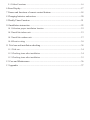
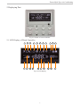
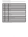
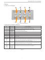
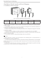
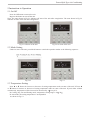
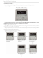
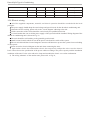
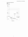
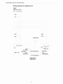
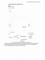
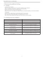
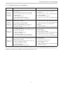
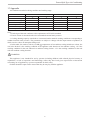
Installation and Operation Manual
Operation Manual of The Ducted Split Type
Air-Conditioning Units
Applicable Models :
FG(R)20/BNa-M FG(R)25/BNa-M
FG(R)30/BNa-M FG(R)40/BNa-M
MUCH-20-H4
MUCH-25-H4
MUCH-30-H4
MUCH-40-H4
Please read this manual carefully before using this product and keep it properly for future reference.
User Notice
MUNDOCLIMA series ducted air-conditioning units are elaborately designed and produced with high
quality, reliability and adaptability.
Please read this instruction thoroughly before operation and maintenance.
The installation should be carried out by the qualified service technicians.
MUNDOCLIMA will not be responsible for the personal injury or property damage resulting from improper
installation and adjustment, unnecessary maintenance and those do not follow the instructions in this manual.
The scope of guarantee must accord with the following items:
The first start-up should be carried out by qualified service technicians appointed by the service center of
MUNDOCLIMA.
The components of air-conditioning units should only be provided by MUNDOCLIMA Company.
The specified time and frequency of the operation and maintenance items in this manual should be strictly
executed.
Any violation of the precedent items will lead to the invalidation of guarantee.
All of the figures and messages are for reference only. Since The MUNDOCLIMA has a policy of
continuous product improvement, he reserves the right to change design and specifications of the
products at any time without notice.
R410A(R32/125: 50/50)
GWP:1900
Contents
1 Safety precautions������������������������������������������������������������������������������������������������ 1
1.1 Safety notice ��������������������������������������������������������������������������������������������������������� 1
1.2 Power supply demand �������������������������������������������������������������������������������������������� 1
2 Displaying Part����������������������������������������������������������������������������������������������������� 2
2.1 LCD Display of Wired Controller�������������������������������������������������������������������������� 2
2.2 Instruction to LCD Display������������������������������������������������������������������������������������ 3
3 Buttons����������������������������������������������������������������������������������������������������������������� 4
3.1 Silk Screen of Buttons�������������������������������������������������������������������������������������������� 4
3.2 Instruction to Function of Buttons�������������������������������������������������������������������������� 4
4 Installation of Wired Controller and Project Debugging������������������������������������� 5
4.1 Installation of Wired Controller������������������������������������������������������������������������������ 5
5 Instruction to Operation��������������������������������������������������������������������������������������� 6
5.1 On/Off��������������������������������������������������������������������������������������������������������������������� 6
5.2 Mode Setting����������������������������������������������������������������������������������������������������������� 6
5.3 Temperature Setting������������������������������������������������������������������������������������������������ 6
5.4 Fan Speed Setting *������������������������������������������������������������������������������������������������ 7
5.5 Swing Control Function *��������������������������������������������������������������������������������������� 7
5.6 Timer Setting���������������������������������������������������������������������������������������������������������� 8
5.7 Air Exchange Setting* ������������������������������������������������������������������������������������������� 9
5.8 Sleep Setting��������������������������������������������������������������������������������������������������������� 10
5.9 Turbo Function Setting������������������������������������������������������������������������������������������11
5.10 Save Function Setting ���������������������������������������������������������������������������������������� 12
5.11 E-heater setting *������������������������������������������������������������������������������������������������ 13
5.12 Blow Function Setting ��������������������������������������������������������������������������������������� 14
5.13 Quiet Function Setting���������������������������������������������������������������������������������������� 15
5.14 Debugging Functions������������������������������������������������������������������������������������������ 16
5.15 Other Functions������������������������������������������������������������������������������������������������������� 16
6 Error Display�����������������������������������������������������������������������������������������������������������17
7 Names and functions of remote control buttons�����������������������������������������������������18
8 Changing batteries and notices�������������������������������������������������������������������������������20
9 Weekly Timer Function�������������������������������������������������������������������������������������������21
10 Installation instruction������������������������������������������������������������������������������������������22
10.1 Selection proper installation location ��������������������������������������������������������������������� 22
10.2 Install the indoor unit ���������������������������������������������������������������������������������������������� 23
10.3 Install the outdoor unit �������������������������������������������������������������������������������������������� 27
10.4 Electric wiring �������������������������������������������������������������������������������������������������������� 30
11 Trial run and installation checking������������������������������������������������������������������������34
11.1 Trial run ������������������������������������������������������������������������������������������������������������������� 34
11.2 Checking items after installation����������������������������������������������������������������������������� 34
11.3 Checking items after installation����������������������������������������������������������������������������� 35
12 Care and Maintenance�������������������������������������������������������������������������������������������36
13 Appendix ��������������������������������������������������������������������������������������������������������������37
Ducted Split Type Air-Conditioning
1 Safety precautions
1.1 Safety notice
Before using the appliance, read this manual thoroughly and operate under its direction.
“WARNING” and “ATTENTION” have the following meanings in these instructions:
WARNING This mark indicates procedures, which if improperly performed, might lead to the death or
serious injury of the users.
ATTENTION This mark indicates procedures, which if improperly performed, might possibly result in
personal injury to the user, or damage to property.
WARNING
Do not use or place combustible and explosive gas or liquid near the air conditioner.
To optimize the life of the appliance, do not install the air-conditioning unit by yourself.
Do stop operation and turn off the power supply immediately in the event of a malfunction (burning smell,
etc.).
Don’t remove the fan guard and not insert fingers or objects into the outlet ports of the indoor and outdoor
unit.
Do not check or fix the air-conditioning unit while it is running.
Do not pour water into the air-conditioning unit and not operate it with a wet hand.
The air-conditioning unit is not equipped with a device to suck fresh air from the outdoors, so when you
are using gas or petrol in the same room, or you feel the room air is dirty, please open the door or window to
exchange the air, but this can affect the adjustment of air conditioning.
ATTENTION
Ensure the power supply correspond to the nameplate and check the security of the power source before
installation.
Make sure that the wires, pipes and drain hose are properly connected before operation to avoid a fire or
electric shock.
Don’t let children operate the ducted air-conditioning unit.
Turn off the power supply whenever cleaning the air-conditioning unit or changing the air filter.
Switch off power source when the units will not be operated for a long period.
Do not step or place objects on the air-conditioning unit.
The appliance shall not be installed in the laundry
1.2 Power supply demand
1)  Provided sufficient capacity of power supply and the cross area of electrical wires.
2)  Confirm the reliable earth connection, and the earth wire should be connected to special device of the
building. Never connect the earth wire to the gas pipe, water pipe, the earth wires of telephone and lighting rod.
3)  Make sure that the wiring is done by the qualified technicians according to the relevant regulations.
4)  In fixed circuit, there must be electricity leakage protection switch of enough power capacity and air
switch with enough space.
5)  An all-pole disconnection device which has at least 3mm separation distance in all pole and a residual
current device(RCD)with the rating of above 10mA shall be incorporated in the fixed wiring according to the
national rule
6)  The appliance shall be installed in accordance with national wiring regulations
7)  The temperature of refrigerant circuit will be high, please keep the interconnection cable away from the
copper tube.
1
Ducted Split Type Air-Conditioning
2 Displaying Part
Fig.2.1 Outline of wired controller
2.1 LCD Display of Wired Controller
1
2
12 13
3
14 15
4
5
6
16 17
7
8
18
Fig.2.2 LCD display
2
9 10 11
19 20
21
Ducted Split Type Air-Conditioning
2.2 Instruction to LCD Display
No.
Description
Instruction to Displaying Contents
1
Swing
2
Air
3
Sleep
4
Running mode
5
Cooling
6
Dry
Dry mode
7
Fan
Fan
8
Heating
Heating mode
9
Defrost
Defrosting state
10
Gate-control
card *
11
Lock
Lock state
12
Shield
Shielding state (buttons, temperature, on/off, mode or save is shielded by long-distance
monitoring
13
Turbo
Turbo function state
14
Memory
Memory state (Indoor unit resumes original setting state after power failure and then
power recovery)
15
Twinkle
Flicking when unit is on without operation of buttons
16
Save
17
Temperature
18
E-Heater*
19
Blow
Blow mark
20
Timer
Timer-displayed location
21
Quiet
Quiet state(two types: quiet and auto quiet)
Swing function
Air exchange function
Sleeping states
Each kind of running mode of indoor unit (auto mode)
Cooling mode
Gate control
Energy-saving state
Ambient/setting temperature value
Mark that E-heater is allowed to turned on
There is not Master and CO2 functions for E series ducted type unit and A2 ducted type and cassette type units
Table 2.1
“*” There is no this function for these units
3
Ducted Split Type Air-Conditioning
3 Buttons
3.1 Silk Screen of Buttons
1
2
3
4
5
6
7
8
Fig. 3.1 Silk screen of buttons
3.2 Instruction to Function of Buttons
No.
Description
Function of Button
1
Enter/cancel
2
▲
6
▼
(1) Running temperature setting of indoor unit, range :16~30
(2) Timer setting, range:0.5-24hr
(3) Switchover between quiet/auto quiet
3
Fan
Setting of high/middle/low/auto fan speed
4
Mode
5
Function
7
Timer
Timer setting
8
On/off
Turn on/off indoor unit
4 Mode
and
2▲
Memory
function
2▲
and
6▼
Lock
4 Mode
and
5 Function
Enquiry
and setting
of address
of wired
controller
(1) Function selection and canceling;
(2) Press it for 5s to enquiry the outdoor ambient temperature.
Setting of cooling/heating/fan/dry mode of indoor unit
Switchover among the functions of air,/sleep/turbo/save/e-heater/blow /quiet
Press them for 5s under off state of the unit to enter/cancel memory function (If
memory is set, indoor unit after power failure and then power recovery will resume
original setting state .If not, indoor unit is defaulted to be off after power recovery.
Memory function is defaulted to be off before outgoing.)
Upon startup of the unit without malfunction or under off state of the unit, press
them at the same time for 5s in to lock state. In this case, any other buttons won’t
respond the press. Repress them for 5s to quit lock state.
Press them for 5s under unit off at the same time to set address.
Table 3.1
4
Ducted Split Type Air-Conditioning
4 Installation of Wired Controller and Project Debugging
4.1 Installation of Wired Controller
1
2
3
4
5
Fig.4.1: Sketch for Installation of Wired Controller
No.
1
2
3
4
5
Description
Socket’s base box
installed in the
wall
Soleplate of
controller
Screw M4X25
Front panel of
controller
Screw ST2.2X6.5
Fig.4.1: Sketch for Installation of Wired Controller. Pay attention to the following items during installation
of wired controller:
1)  Cut off power supply of heavy-current wire embedded in mounting hole in the wall before installation. It
is prohibited to perform the whole procedure with electricity.
2)  Pull out 4-core twisted pair line in mounting hole and then make it through the rectangle hole at the back
of controller’s soleplate.
3)  Joint the controller’s soleplate on wall face and then fix it in mounting hole with screws M4X25.
4)  Insert the 4-core twisted pair through rectangle hole into controller’s slot and buckle the front panel and
soleplate of controller together.
5)  At last, fix the controller’s front panel and soleplate with screws ST2.2X6.5.
Caution:
During connection of wirings, pay special attention to the following items to avoid interference of
electromagnetism to unit and even failure of it.
1)  To ensure normal communication of the unit, signal line and wiring (communication) of wired controller
should separate from power cord and indoor/outdoor connection lines. The distance between them should be
kept 20cm in min.
2)  If the unit is installed at the place where there is interference of electromagnetism, signal line and wiring
(communication) of wired controller must be shielding twisted pair lines.
5
Ducted Split Type Air-Conditioning
5 Instruction to Operation
5.1 On/Off
Press On/Off button to turn on the unit.
Repress this button to turn off the unit.
Note: The state shown in Fig.5.1 indicates off state of the unit after energization. The state shown in Fig.5.2
indicates on state of the unit after energization.
Fig.5.1 Off state of the unit
Fig.5.2 On state of the unit
5.2 Mode Setting
Under on state of the unit, press Mode button to switch the operation modes as the following sequence:
Fig.5.2.1
Fig 5.3
5.3 Temperature Setting
Press ▲ or ▼ button for increase or decrease of setting temperature under on state of the unit. If Press ▲
or ▼ button for increase or decrease of setting temperature under on state of the unit. If press either of them
continuously, temperature will be increased or decreased by 1 every 0.5s.
In Cooling, Dry, Fan and Heating mode, temperature setting range is 16 ~30 .
In Auto mode, the setting temperature is un-adjustable.
As shown in Fig.5.3
6
Ducted Split Type Air-Conditioning
5.4 Fan Speed Setting *
Under on/off state of the unit, press Fan button, fan speed of indoor unit will change as below:
As shown in Fig.5.4
Fig.5.4
(Indoor unit about FG(R)20/BNa-M,FG(R)25/BNa-M,FG(R)30/BNa-M and FG(R)40/BNa-M can only run
at high fan speed mode and fan speed can’t be modified by wired controller.)
5.5 Swing Control Function *
Under on state of unit, press Function button till the unit enters swing control function and then press “Enter/
cancel “ button to turn on turbo control function.
During swing function, press Function button till the unit enters swing control function and then press Enter/
cancel button to cancel swing control function.
Swing control function setting is shown in Fig 5.5
There is no this function for this unit.
Fig 5.5
7
Ducted Split Type Air-Conditioning
5.6 Timer Setting
Under on state of the unit, press Timer button to set timer off of the unit. Under off state of the unit, press
Timer button to set timer on of the unit in the same way.
Timer on setting: Under off state of the unit without timer setting, if Timer button is pressed, LCD will
display xx. Hour, ON blinking. In this case, press▲ or ▼ button to adjust timer on and then press Timer to
confirm. If Mode button is pressed before pressing Timer button to confirm, timer mode will be switched to
timer off setting mode. In this case, LCD displays xx. Hour, OFF blinking. In this case, press▲ or ▼ button to
adjust timer off and then press Timer to confirm. When LCD displays xx. Hour On Off, xx. Hour means time of
timer on, but time of timer off won’t be displayed.
Timer off setting: Under on state of the unit without timer setting, if Timer button is pressed, LCD will
display xx. Hour, OFF blinking. In this case, press▲ or ▼ button to adjust timer on and then press Timer to
confirm. If Mode button is pressed before pressing Timer button to confirm, timer mode will be switched to
timer on setting mode. In this case, LCD displays xx. Hour, ON blinking. In this case, press▲ or ▼ button to
adjust timer on and then press Timer button to confirm. When LCD displays xx. Hour On Off, xx. Hour means
time of timer off, but time of timer on won’t be displayed.
Cancel timer: After setting of timer, if Timer button is pressed, LCD won’t display xx. Hour so that timer
setting is canceled.
Timer off setting under on state of the unit is shown as Fig.5.6
Fig.5.6 Timer setting under on state of the unit
Timer range: 0.5-24hr. Every press of▲ or ▼ button will make setting time increased or decreased by 0.5hr.
If press either of them continuously, setting time will automatically increase/ decrease by 0.5hr every 0.5s.
Note:
1)  If both timer on and timer off are set in unit on interface, the wired controller only display time of time
off after confirmation of timer. If both of them are set in unit off interface, only time of timer on is displayed.
2)  Timer on in unit on interface is timed from the time of unit off and timer off in unit off interface is timed
from the time of unit on.
8
Ducted Split Type Air-Conditioning
5.7 Air Exchange Setting*
Turn on air function: Under on state of the unit, press Function button into this function setting (Air mark
blinks).AIR 1 displayed at the ambient temperature-displayed location (888) is defaulted (the last type of AIR
will be displayed after adjustment).Press ▲ or ▼ button to adjust air type. Press Enter/Cancel button to turn on/
off air function. After turning on this function, the air mark shows.
There are 10 types of AIR, but only 1-2 types are for remote control. Refer to the following details:
1――The unit continuously runs for 60min, and fresh air valve runs for 6 min.
2――The unit continuously runs for 60min, and fresh air valve runs for 12 min.
3――The unit continuously runs for 60min, and fresh air valve runs for 18 min.
4――The unit continuously runs for 60min, and fresh air valve runs for 2 4 min.
5――The unit continuously runs for 60min, and fresh air valve runs for 30 min.
6――The unit continuously runs for 60min, and fresh air valve runs for 36 min.
7――The unit continuously runs for 60min, and fresh air valve runs for 42 min.
8――The unit continuously runs for 60min, and fresh air valve runs for 48 min.
9――The unit continuously runs for 60min, and fresh air valve runs for 54 min.
10――Both of them run.
Turn off air function: During Air function, press Function button into Air function. In this case, air mark is
blinking, and then press Enter/cancel button to turn off this function. Air mark will subsequently disappear.
Air setting is shown as in fig.5.7:
Fig.5.7 Air exchange device
Note:
In air exchange mode, press Function button or there is not any operation within 5s after the last button
operation, the system will quit from air exchange setting and current energy-saving date won’t be memorized.
9
Ducted Split Type Air-Conditioning
5.8 Sleep Setting
Sleep on: Press Function button under on state of the unit into sleep function and then press Enter/cancel
button to turn on sleeping function.
Sleep off: During sleep on state, press Function button into sleep function and then press Enter/cancel button
to turn off this function.
Sleep setting is shown as Fig.5.8:
Fig.5.8 Sleep setting
Sleep off is default after power failure and then power recovery. There is not sleep function in fan and auto
mode.
Note:
In cooling and dry mode, if the unit with sleep function has run for 1 hour, the preset temperature will be
increased by 1 and 1 in another 1 hour. After that, the unit will run at this temperature. In heating mode, if
the unit with sleep function has run for 1 hour, the preset temperature will be decreased by 1 and 1 in another
1 hour. After that, the unit will run at this temperature.
10
Ducted Split Type Air-Conditioning
5.9 Turbo Function Setting
Turbo function: The unit at high fun speed can realize quick cooling or heating so that room temperature can
quickly approach setting temperature.
In cooling or heating mode, press Function button till the unit enters turbo function and then press Enter/
cancel button to turn on turbo function.
During turbo function, press Function button till the unit enters turbo function and then press Enter/cancel
button to cancel turbo function.
Turbo function setting is shown in Fig5.9:
Fig.5.9 Turbo Function Setting
Note:
1)  Turbo function will be turned off after power failure and then recovery. In dry, fan and auto mode, turbo
function can not be set and turbo mark won’t be displayed.
2)  Turbo function will be automatically canceled after setting of quiet function.
11
Ducted Split Type Air-Conditioning
5.10 Save Function Setting
Energy Saving Function: Energy saving result that the air conditioner runs in smaller temperature range is
realized by setting lower limited value of setting temperature in cooing or dry mode and upper limited value in
heating mode.
Energy Saving Setting for Cooling
Under on state and in cooling or dry mode of the unit, press Function button into energy saving function ,
SAVE blinking .Press ▲ or ▼ button to adjust lower limited value of setting temperature in cooing mode. After
that press Enter/Cancel button to turn on energy saving function for cooling.
Energy Saving Setting for Heating
Under on state and in heating mode of the unit, press Function button into energy saving function, SAVE
blinking. Press Mode button into energy saving function for heating and then press▲ or ▼ button to adjust
upper limited value of setting temperature in heating mode. After that, press Enter/Cancel button to turn on
energy saving function for heating.
After energy saving function is turned on, press Function button into energy saving function and press Enter/
cancel to cancel this function.
The energy saving setting is shown in the fig.5.10.
Fig.5.10 Energy Saving Setting
Note:
1)  In Auto running mode with save function on, the unit will be forcibly changed to corresponding mode.
After setting of save, sleep function will be canceled.
2)  In save mode, if Function button is pressed or there is not any operation within 5s after the last button
operation, the system will quit from save function setting and current data won’t be memorized.
3)  After power failure and then recovery, save function setting will be memorized.
4)  The lower limited value in cooling mode is 16 and the upper limited value in heating mode is 30 .
5)  After save setting, if the setting temperature is out of the range in the mode, the limited value will prevail.
12
Ducted Split Type Air-Conditioning
5.11 E-heater setting *
There is no this function for this unit
E-heater: In heating mode, E-heater is allowed to be turned on for improvement of efficiency.
If heating mode is turned on by button operation, auxiliary electric heating function will be automatically
turned on.
Press Function button in heating mode into auxiliary electric heating function, E-HEATER blinking, and
press Enter/cancel button to turn on this function. In this case, E-HEATER will be displayed, which means
E-heater is allowed to be turned on.
If auxiliary electric heating function is on, press Function button to confirm or press Enter/cancel button to
cancel. In this case, E-HEATER won’t be displayed, which means E-heater is prohibited to be turned on.
The setting of this function is shown as Fig.5.11 below:
Fig. 5.11 Auxiliary Electric Heating Function Setting
Note:
1)  E-heater can not be set in cooling, dry and fan mode, E-heater mark won’t be displayed. The setting is
shown in Fig.5.11.
2)  There is not E-heater for A2 and cassette unit.
13
Ducted Split Type Air-Conditioning
5.12 Blow Function Setting
Blow function: After the unit is turned off, water in evaporator of indoor unit will be automatically
evaporated to avoid mildew.
In cooling and dry mode, press Function button till the unit enters dry function, BLOW blinking, and then
press Enter/cancel button to turn on this function.
In blow mode, press Function button till the unit enters blow function and then press Enter/cancel button to
cancel this function.
Dry function setting is shown in Fig.5.12
Fig.5.12 Blow function setting
Note:
1)  After setting dry function, turn off the unit by pressing On/Off button or remote controller, indoor fan
will run at low fan speed for 10 min. (BLOW shows).Meanwhile, if dry function is canceled indoor fan will be
turned off directly.
2)  There is not BLOW function in fan or heating mode.
14
Ducted Split Type Air-Conditioning
5.13 Quiet Function Setting
Quiet function consists of two kinds: quiet and auto quiet.
Press Function button till the unit enters quiet function setting state, Quiet or Auto Quiet mark blinks. In this
case, press▲ or ▼ button to switch between Quiet and Auto Quiet and then press Enter/cancel button to turn on
this function.
In quiet mode, press Function button till the unit enters quiet function. In this case, Quiet or Auto Quiet icon
blinks and then press Enter/cancel button to cancel this function.
Quiet function setting is shown in Fig.5.13
Fig.5.13 Quiet function setting
Note:
1)  During quiet function, fan speed is un-adjustable.
2)  When turning on auto quiet function, the unit will enter quiet running state according to temperature
difference between room temperature and setting temperature. In this case, fan speed is adjustable. If
temperature difference between room temperature and setting temperature 4 , fan will keep its current speed;
if 2
temperature difference 3 ; fan speed will be reduce one grade ,but if it is at min. grade, it is unadjustable.; if temperature difference 1 , fan speed will be at min. grade
3)  In auto quiet mode, fan speed can not be raised but reduced. If high fan speed is manually adjusted, auto
quiet mode will quit.
4)  There is not auto quiet function in fan or dry mode. Quiet off is default after power failure and then
power recovery.
5)  If quite function is set, turbo function will be canceled.
15
Ducted Split Type Air-Conditioning
5.14 Debugging Functions
Under off state of the unit, press Function and Timer buttons continuously for 5s into debugging menu. Press
Mode button to adjust the setting items and ▲ or ▼ button to set the actual value.
5.14.1 Ambient Temperature Sensor Setting
In debugging mode, press Mode button to adjust the temperature displayed location displaying 00, and press
▲ or ▼ button to adjust setting state at timer displayed location. There are 3 types for selection:
(1)  Indoor ambient temperature is that at return air inlet (01 is displayed at timer displayed location)
(2)  Indoor ambient temperature is that at the place of displayer (02 is displayed at timer displayed location)
(3)  Return air inlet temperature sensor shall be selected for cooling, dry and fan modes and wired
controller temperature sensor (03 is displayed at timer displayed location) shall be selected for heating
and auto modes.
5.14.2 Three Grades of Speed for Indoor Fan
In debugging mode, press Mode button to adjust the temperature displayed location displaying 01 and press
▲ or ▼ button to adjust setting state at timer displayed location. There are 2 types for selection:
(1)  3 low grades ( LCD displays 01)
(2)  3 high grades ( LCD displays 02)
Three low grades indicate high, medium and low grades and 3 high grades indicate super-high, high and
medium grades.
Press Enter/Cancel button to save the setting and quit after setting. If there is not any operation within 20s
after the system responds the latest button operation in this interface, the system will quit this menu and display
normal off state; meanwhile, current setting won’t be saved.
5.15 Other Functions
5.15.1 Lock Function
Upon startup of the unit without malfunction or under off state of the unit, press ▲ and ▼buttons at
the same time for 5s till the wired controller enters lock state. In this case, LCD displays
repress these two buttons at the same time for 5s to quit lock state.
. After that,
Under lock state, any other buttons won’t give any response to the press.
5.15.2 Memory Function
Memory switchover: Under off state of the unit, press Mode and ▲ buttons at the same time for 5s to switch
memory modes. During setting memory mode, Memory will be displayed. If this function is not set, the unit
will be under off state after power failure and then power recovery.
Memory recovery: If memory mode has been set for wired controller, the wired controller after power failure
will resume its original running state upon power recovery.
Note:
It will take about 5s to save all the information. Please don’t cut down the power after content changed in 5
second, or It may be fail to save the content.
5.15.3 Gate-control Display Function*
If there is gate control system, the unit can run after plugging in card and stop after pulling out the card.
If memory function is on, the unit after plugging out of card and then plugging in will run according to the
memory. If the card is not plugged in (or poor plugging), the mark
will show and the unit will be turned off.
If memory function is off, the unit after plugging out the out will be turned off and the mark
will show.
If re-plugging in the card, the mark will disappear and the unit enter will enter off state.
Note:
1)  During long-distance monitoring, the unit on /off can not be controlled by the card, but the mark
will
also show after plugging in the card.
2)  The unit can not be controlled by button operation after plugging out the card.
16
Ducted Split Type Air-Conditioning
5.15.4 Enquiry of Outdoor Ambient Temperature
Under on or off state of the unit, press Enter/Cancel button for 5s, outdoor ambient temperature will be
displayed at temperature displaying area after a sound of click .Pressing any button, this enquiry state will quit.
If there is not any operation for 20s, it will automatically quit.
Note:
1)  This function will be shielded after energization of 12hr for some models of the units without outdoor
ambient sensors. Please refer to Instruction for details.
2)  If malfunction of outdoor ambient sensor occurs, this function will be shielded in 12hr.
5.15.5 Selection of Centigrade and Fahrenheit
Under off state of the unit, press Mode and ▼ at the same time for 5s, the displayer panel will switch
between Centigrade and Fahrenheit.
6 Error Display
If there is malfunction during running of the system, LCD will
display error code at temperature–displayed location. Once many
malfunctions, error codes will be displayed circularly. If there
are multiple systems, the system number of failed system will
be displayed before the colon (not for single system).
If malfunction occurs, please turn off the unit and ask professionals
for help.
As shown in Fig.6.1, it means high pressure protection of system
2 under unit on.
Note:
Only Big Wind Pipe series have multiple units.
Multi-system is only for air cooled packaged unit
Fig.6.1
Error code meaning:
Error code
E0
E1
E2
E3
E4
E5
E6
E9
F0
F1
F2
F3
F4
F5
EH*
C5*
C1*
C2*
Malfunction
Water pump malfunction
High pressure protection of compressor
Indoor anti-freezing protection
Low pressure protection of compressor
High discharge temperature protection of compressor
Compressor overload protection
Communication malfunction
Water overflow protection (Note: it is indoor fan motor protection
instead for the 30KW unit.)
Indoor unit ambient sensor malfunction at air return opening
Evaporator sensor malfunction
Condenser sensor malfunction
Outdoor unit ambient temperature sensor mal.
Discharge temperature sensor malfunction
Ambient sensor malfunction on Displayer(or LED board)
Auxiliary electric heating malfunction
Wire jumper cap malfunction
Arc protection
Creepage protection
“*” There is no this function for these units.
17
Ducted Split Type Air-Conditioning
7 Names and functions of remote control buttons
Notes: This remote control is universal .It could be used for many units. Some buttons which are not available
in this unit will not be described below.
1. “ON/OFF” button
After powering the unit, when the unit is off state, press the “ON/OFF” button to start the unit. AND when
the unit is on state, press the button ,it will be off.
2. “Mode” button
Press this button , the unit will be run in the mode which you want. Press this button once, the mode will be
changed in a regular as AUTO –COOL –DRY –FAN – HEAT.
AUTO;
COOL;
DRY;
FAN;
HEAT
3.“+” ,“–” button
Press the “+” or “–” button to set your desired temperature. The temperature range is from 16 to 30 .It
is not necessary at AUTO mode. AND when you are setting the timing hours, press the “+” or “–” button once,
the timing hours will increase or decrease 0.5 hour.
4.“FAN” button*
Press the “FAN” button to set fan speed. The AUTO FAN,LOW,MID,HIGH could be selected.
(Indoor unit about can only run
at high fan speed mode and fan speed can’t be modified by wired controller.)
There is no this function for this unit
5.
button *
There is no this function for this unit. If press this key, the main unit will click, but it also runs under
original status.
18
Ducted Split Type Air-Conditioning
6.
button*
There is no this function for this unit. If press this key, the main unit will click, but it also runs under original
status.
7.“SLEEP” button
Press this button to set the sleep mode. Once the sleep mode is set , the temperature will increase 1 after 1
hour, and still increase another 1 after 2 hours in the COOL mode. While in HEAT mode , the temperature will
decrease 1 after 1 hour, and still decrease another 1 after 2 hours .
8.“TIMER” button
Press the button to set the timing function. When the timing function is on, press this button to cancel the
function. When the timing function is off, press this button once, words Hour on(off) will appear and flicker.
In this case, press +/- button to adjust time (press +/- button continuously to change timing value quickly),the
setting time range is from 0.5 to 24 hr; press this key once again to fix the time, then remote controller will send
out the signal immediately and hour on/off will stop flickering. If the time of that no press timer button under
filcking status is above 5s, the timer setting will quit. If the timer has been set, press this button once again to
quit it.
9.“TURBO” button
Set turbo on or off(the characters of turbo will appear of disappear) by pressing this key under cooling or
heating mode. Once energized, the unit will be defalted to be turbo off. This function can not be set under auto,
dehumidify or fan mode, and characters of turbo won’t appear.
10.“BLOW” button
Set Blow on or off (the characters of Blow will appear of disappear) by pressing this key under cooling
or dehumidify mode. Once energized, the unit will be defaulted to be Blow off. Set E-Heater on or off (the
characters of E-Heater will appear of disappear) by pressing this key under heat mode. Once energized, the
unit will be defalted to be E-Heater off. Blow and E-Heater function can not be set under auto or fan mode, and
characters of Blow won’t appear.
11.“Light” button*
There is no this function for this unit. If press this key, the main unit will click, but it also runs under original
status.
12.“Temp” button*
There is no this function for this unit. If press this key, the main unit will click, but it also runs under original
status.
13.“HEALTH |SAVE” button*
There is no this function for this unit. If press this key, the main unit will click, but it also runs under
original status.
About AUTO RUN
When AUTO RUN mode is selected, the setting temperature will not be displayed on the LCD .The unit
will be accordance with the room temp, automatically to select the suitable running mode and to make ambient
comfortable.
About turbo function
If start this function, the unit will run at super-high speed to cool or heat quickly so that the ambient temp
approachs the preset temp as soon as possible.
About LOCK
Press “+” and “–” simultaneously to lock or unlock the keyboard. If the remote control is locked, the icon
will be displayed on the LCD, in which case, press any button , the mark will flicker for three times. If the
keyboard is unlocked, the mark will disappear.
About switch between Fahrenheit and Centigrade
Under status of unit off, press MODE and – buttons simultaneously to switch and .
19
Ducted Split Type Air-Conditioning
8 Changing batteries and notices
1) Slightly to press the place with
controller.(As show in Fig 8.1.)
2) Take out the old batteries ,insert two AAA alkaline cells(As show in Fig 8.2.)
3)
OPEN
Fig 8.1
Fig 8.2
NOTE:
When changing the batteries, do not use the old or different batteries, otherwise, it can cause the
malfunction of the wireless remote control.
If the wireless remote control will not be used for a long time, please take them out . and do not let the
leakage liquid damage the wireless remote control .
It should be placed where is 1m away from the TV set or stereo sound sets.
If the remote control cannot operate normally, please take the batteries out, and then reinsert it 30s later; if
it is also abnormal, please replace the batteries.
When the remote controller sends out single, a make
“*” There is no this function for these units.
20
Ducted Split Type Air-Conditioning
9 Weekly Timer Function
7DP - Seven days programmer (Accessory not supplied)
Centralized Control and Week Timer Functions: The centralized controller and the weekly timer are
integrated in the same wire controller. The system has both the centralized control and the week timing
functions. Up to 16 sets of units can be controlled simultaneously by the centralized controller (weekly timer).
The weekly timer has the function of invalidating the lower unit. The weekly timing function is able to realized
four timing ON/OFF periods for any unit everyday, so as to achieve fully automatic operation.
This WEEKLY TIMER adopts 485 modes to communicate with manual control of every duct type unit,
and it can control up to 16 units. Adopting2-core twisted-pair wire, the longest communication distance of this
TIMER is 1200m. After connected to power, the WEEKLY TIMER can display all connected units (sequence of
unit is determined by code switch of manual control of every duct type unit). On and off of every duct type unit
can be done through the Timer On / Off of this WEEKLY TIMER, and the button shield operation of manual
control can be done through shield setting on WEEKLY TIMER. Mode selection and temperature adjustment
and other operations are done through the manual control at every unit.
1
2
3
4
5
6
7
8
9
Composition of programmer wall week
Unit dispaly
10
Single/group display
11
Timer week display
12
Timer display
13
Timer state display
14
Timer time period display
15
Timer ON/OFF time display
16
Unit on display
17
Unit off display
Clock display
Confirm button
Increase button
Cacel/delete button
Single/group button
Timer/time button
ON/OFF button
Note:   Please let us know your requirement before your placing the order, for this WEEKLY TIMER will only
be prepared when customer orders(communication joint with WEEKLY TIMER on manual control had been
prepared).
21
Ducted Split Type Air-Conditioning
1. Press ▲ or ▼ to select the unit that needed to be control. It is available to control several units by
Group Control (1~16), or control single unit by Single Control.
2. When selected a certain or several units by Single Control or Group Control, Timer setting and On/off
setting can be set. Timer setting can set 4 on/off times in a day in one week; and on/off setting can be done by
pressing on/off button.
3. Connection between WEEKLY TIMER and manual control is shown as following:
4. please check the manual to read how to set the address of manual.
10 Installation instruction
The installation must accord with local regulation, and must be carried out by the professionals. Never
carry out the work by yourself without the help of professionals. And don’t supply power, until all the
work is finished according to the user’s manual.
10.1 Selection proper installation location
1) Selection the proper location for indoor unit
Avoid the direct sunshine.
Make sure the suspension bracket is strong enough to withstand the unit’s weight.
Select a place for easily connection of the drain hose.
The inlet and outlet ports should not be obstructed so that the indoor air circulates well.
Make sure the convenient connect of the connection pipes.
Selection a location that is far away from the combustible or explosive material and gas.
Selection a location that is far away from the cankerous material, frog, dusk or moist.
2) Selection the proper location for outdoor unit
Outdoor unit should be installed in a steady and stable place.
To reduce the length of the refrigerant pipe and bend number, make sure the indoor unit and outdoor unit
be close to each other.
Ensure the operation noise do not disturb neighbors and passerby.
22
Ducted Split Type Air-Conditioning
Do not install the unit where it will be exposed to direct sunlight or other radiation heat source, or the
awning or a rainproof cloth should be utilized.
The inlet and outlet port should not be blocked.
Make sure the well air circulation.
Selection a location that is far away from combustible or explosive material, dust, fog or moist.
Don’t connect any air leading duct to the outdoor unit, at neither the air inlet nor the air outlet. The
outdoor unit will drop condensate while running at heat mode. If the temp is minus, it will form ice.
Don’t let the rain proof interfere the ventilation of outdoor unit.
10.2 Install the indoor unit
1) The dimensions of installation hole and the intake/outlet port are shown in Fig. 19 and Table 1.
c
f
e
Air Outlet
b
b
Air Return
e
Air Outlet
f
d
a
c
a
a. 20KW,25KW ,30KW
b. 40kW
Fig. 19 Indoor unit installation position and dimension
Table 1 Outlines and dimension of the unit
Model
MUCH-20-H4
MUCH-25-H4
MUCH-30-H4
MUCH-40-H4
a
1353
1560
1560
1780
Unit: mm
b
632
910
910
1040
c
992
331
1194
868
d
1150
1194
1194
1450
e
192
292
292
347
f
343
342
342
555
2) Main body of the indoor unit The indoor unit should be installed horizontally and the demand of
installation space is shown in Fig. 20. To install an indoor unit needs 4 hanging rods, and each hanging rod
should at least withstand four times of the unit’s weight.
23
Ducted Split Type Air-Conditioning
Suspender
>560
>1000
Hook
Flat
washer
Air supply
Spring
washer
Nut
>1000
Installation of suspender
Air return
Fig.20 Schematic for the indoor unit
B
A
3) Drain hose
For easy drainage of the condensation water, the should be installed with a downward gradient. To avoid
the condensation, the connection pipe joint should be insulated with thermal insulation material. A water seal
should be employed as shown in Fig. 19 and the height of the water seal could be determined by the pressure of
the drain hose.
Drain hose is in negative pressure state: A = B P/10+20 (mm)
Drain hose is in positive pressure state: A 30mm,B P/10+20 (mm)
Note: P is the absolute pressure of the drain hose position, Pa
Drain hose
Water seal
4) Refrigerant pipe insulation layer
To avoid condensation of drew and water leakage, gas pipe and liquid pipe of refrigerant should be insulated
with thermal insulation material and adhesive tape.
24
Ducted Split Type Air-Conditioning
5) Install the Electrical Box. (Be Suit For 25KW~40KW)
In order to ease the maintaining work, we recommend to get of the electrical box part of the indoor unit to
refix it at the air outlet part. Please see following Fig 21.
Fig. 21 Schematic for the Electrical Box part
6) Install the wired remote controller
A pit or a hole in the suitable position of the wall should be reserved for the connection signal cables.
The connection wire between indoor unit and controller can be laid in the pit with 1# PVC pipe for direct
installation (Figure 22). For concealed installation, 1# PVC can also be utilized (Figure 23).
Both Cable of direct installation and the concealed one, please drill two horizontal hole on the wall and
insert two wooden plug. Then fix the soleplate on the wall and insert the signal wire pin into the plug as showed
in Figure 24, finally fix the controller to the wall..
Installation of the Wired Controller
25
Installation of the Wired Controller
Ducted Split Type Air-Conditioning
Dismantlement of the Wired Controller
7) Connection of the signal wire
Open the electrical box;
Plug the wire through the PVC pipe;
Plug the wire onto the four-nail sea;
Tighten the wire;
The max length between controller and the PCB board is 20m.
8) Setting of Double Indoor Room Sensors
This series of ducted air-conditioning unit has two indoor room sensors. One is located at the air intake of
the indoor unit and the other one is located inside the wire controller.
User can select one from the two indoor room sensors on the basis of the engineering requirement.
(Refer to the section of wire controller instructions for detailed operation.)
Indoor Room Sensor A
Indoor Room Sensor B
9) Checking of Outdoor Ambient Temperature
The outdoor ambient temperature can be checked on the wire controller for the convenience of users before
going out. (Refer to the section of wire controller instructions for detailed operation.)
,QGRRU6LGH
2XWGRRU6LGH
2XWGRRU
5RRP6HQVRU
26
Ducted Split Type Air-Conditioning
10) Information for fuse
MUCH-20-H4
MUCH-25-H4
MUCH-30-H4
MUCH-40-H4
Fuse
Model
code
Indoor
T5AL 250V
46010013
Outdoor
T3.15AL 250V
46010014
Indoor
T3.15AL 250V
46010014
Outdoor
T3.15AL 250V
46010014
11) Adjust the tightness of the belt of the fan unit (Be Suit For 25KW~40KW)
The rotation of the fan is achieved by the transmission of the belt. The velocity and stability of the fan is
associated with the tightness of the belt and the tightness should be adjusted after a period of time. For a new
belt, the tightness should be adjusted for at least twice within 24 hours.
After one week running, the tightness of the belt should be adjusted again, we should routinely check it
every 1-2 months; also ensure the test results complying with Table 2.
The adjustment of the tightness of the belt is shown in Fig. 25. Loosen screws fixing motor on the base,
move motor along the direction of arrow as shown in the picture, then fix the screw again.
The tightness level of belt is tested by tensiometer as shown in Fig. 26, when reaches the deviation
length(Deviation=The total length beit/64) ,read the value on the meter, the value should be in the category
specified in Table 2.
Table.2 Tension range of the belt
Belt Section
Diameter of the small wheel (mm)
SPA
80~132
56~95
100~140
SPZ
Tension (N)
Min
25
13
20
Max
35
20
25
0RXQWLQJSODWH
IRUPRWRU
%HOWWHQVLRPHWHU
1XW
1XW
6HWWLQJOHYHU
Fig. 25 Adjust the tightness of the belt
Fig. 26 Utilization of the belt tensiometer
27
Ducted Split Type Air-Conditioning
10.3 Install the outdoor unit
1) Outline and dimension of the outdoor unit
360
C
A
193
488
B
287
Fig 27 Schematic of the Outdoor unit
Model
MUCH-20-H4
MUCH-25-H4
A(mm)
1150
1150
B(mm)
422
422
C(mm)
1350
1600
1772
840
880
A
B±2
844±2
C±2
Fig 28 Schematic of the Outdoor unit
Model
MUCH-30-H4
MUCH-40-H4
A(mm)
990
1290
2) Installation position
28
B(mm)
787
1160
C(mm)
337
850
>3000
>1000
Ducted Split Type Air-Conditioning
>200
>1200
Front
Back
>1000
Side with
Electrical
>1000
>1000
Fig 29 Schematic for the installation of the outdoor unit
>300
>2000
>500
>2000
>500
>500
Fig 30 Schematic for the installation of the outdoor unit
Fig 31 Crane way schematic
When removing the outdoor unit, two ropes are needed to hang the unit along the four ways. In order to
avoid the excursion, the angle between the ropes should be less than 40 degree.
Please use M12 to tight the support fundus.
3) Refrigerant pipe connection
Note:Do not loosen the cap of the pipes when connecting the pipes between the indoor unit and the
outdoor unit. Connecting the pipes as soon as possible after loosening the cap of the pipes to avoid the
29
Ducted Split Type Air-Conditioning
entering of water and dusk. A metal pipe should be utilized if a pipe should be installed through a wall.
The connection of the pipes should confirm to the following principles:
Make sure to lessen the length of connecting pipe, the height difference between the indoor and outdoor
unit, and the number of bends, and enlarge the diameter of bends.
The permitted maximum value of each case:
Height difference between the indoor and outdoor unit
90 Number of bends
30m
12
Length of connecting pipes
50m
O
The pipe meld type could be employed for the connection of the pipes between the indoor and outdoor
units.
The pipe joint should be tightly connected when a pipe joint is employed between two pipes. It is better to
use only one connecting pipe if the distance is not far.
The pipes should not be shriveled when the pipes are connecting. The bend diameter should be longer
than 200 millimeter. The connecting pipes should not be extended or curved frequently and the curving process
should not be larger than 3 times in the same bending position.
4) Vacuum evacuating, leakage testing and refrigerant charging
The system is charged with nitrogen gas from the low-pressure valve until the pipe pressure increasing to
1Mpa, and the leakage is examined at the connecting or welding position with soap water. The air is evacuated
in the pipe from the check valve with a vacuum pump if no leakage exists, then loosens the cores of the liquid
valve and gas valve and clears the soap water with dry cloth.
If the vacuum pumps and high-pressure nitrogen are not available, we can operate as following:
Remove the cores of the liquid valve and gas valve and loosen the cores of check valve on the gas valve
and the gas will exhaust. Keep exhausting for 15 seconds, tightening the check valve as refrigerant gas coming
out.
Loosen the liquid valve and gas valve.
Tighten the bonnet of the valve, and examine the air leakage at the connecting position with soap water
or gas leakage detector, then clear the soap water with dry cloth.
Wrap the flare nut with insulation material to avoid the condensation dropping after finishing the
preceding procedure.
The refrigerant in the conditioner unit is enough for the connecting pipes of 7.5 meters, if the pipe is longer
than 7.5 meters, additional supplement refrigerant should be supplied. The maximum pipe length is 50 meters.
When the height difference between the indoor unit and outdoor unit is larger than 10 meters, an oil bend should
be employed for every 6 meters.
Outdoor
6m
Oil bend
Indoor
Oil bend
Additional supplement refrigerant as per the extended connection pipe:
Item
Model
Size of Fitting Pipe (mm)
Gas Pipe
Max. Pipe
Length (m)
Liquid Pipe
30
Max. Height
Difference
between Indoor
Unit and Outdoor
Unit(m)
Amount of Additional
Refrigerant to be
Filled (For Extra
Length of Pipe)
(Standard Pipe Length
7.5m)
Ducted Split Type Air-Conditioning
MUCH-20-H4
3/4
3/8
50
30
54 g/m
MUCH-25-H4
1
3/8
50
30
54 g/m
MUCH-30-H4
9/8
1/2
50
30
110g/m
MUCH-40-H4
9/8
5/8
50
30
170g/m
10.4 Electric wiring
All of the supplied components, material, and electric operation should be accorded with the local
principles.
The power supply should adopt the rated voltage and special circuit for the ducted air-conditioning unit.
About the electric working, please refer to the “circuit diagram” adhering to the unit.
All the connection of the circuit should be carried out by the qualified electrician.
A circuit breaker that can cut all the power supply of the system should be installed. Wiring diagram of the
ducted air-conditioning unit is shown in Fig. 32.
The units should be well earthing to the ground by professionals.
Install a central switch which can cut all the power switch and air switch of the system.
The air switch should have hot and magnetic auto-turn-off function to protect the system from overloading
or short power.
Please accord to electrical diagram on the unit when connecting the wires.
1)  Open indoor electric box and outdoor electric box respectively and put the wires cross the electric
boxes. Please choose the specification of the power cables according to the power capacity and the installation
conditions of the unit. Fix the wires with wire clamp and assemble the electric cover after confirmation.
2)  The wiring schematic of the outdoor unit, please refer to Fig 32,
31
Ducted Split Type Air-Conditioning
11 Trial run and installation checking
11.1 Trial run
1) Preparation for trial run
The power supply should be turned on only after finishing all the installation.
All the control wires and cables are connected correctly and safely.
Open the cut-off valves in the gas and liquid pipes.
All the objects like screws and wires etc that remained in the machine should be cleared after installation.
2) Trial run
Switch on power supply and press the ON/OFF button to start operation.
Select FAN mode to check if the phases of the indoor motor are correct.
Select COOL, HEAT and FAN mode and check if the machine operates normally.
11.2 Checking items after installation
Item Possible defects Checking
Has it been fixed firmly?
How is the installation?
The unit may drop, shake or emit noise.
Have you done the refrigerant leakage test?
It may cause insufficient refrigerating capacity.
Is heat insulation sufficient?
It may cause condensation and dripping.
Does the unit drain well?
It may cause condensation and dripping.
Is the voltage in accordance with the rated voltage marked
on the nameplate?
It may cause electric malfunction or damage the part.
Is the electric wiring and piping connection installed
correctly and securely?
It may cause electric malfunction or damage the part.
Has the unit been connected to a secure earth connection?
It may cause electrical leakage.
Is the power cord specified?
It may cause electric malfunction or damage the part.
Has the inlet and outlet been covered?
Insufficient refrigerating capacity.
Has the length of connection pipes and refrigerant capacity
been recorded?
The refrigerant capacity is not accurate.
35
Ducted Split Type Air-Conditioning
11.3 Checking items after installation
Malfunction
Possible cause
Solution
Ducted air
conditioning
unit can not
start-up
1. The power supply does not connect or improper
phase sequence.
2.The electricity leakage switch is switching
off for the leakage of electricity from the air
conditioner units
3. The voltage is too low
4. The operating button is closed
5.The control system is in malfunction
1. Connect the power supply or change two
random phase
2. Contact the service center of MUNDOCLIMA
3. Contact the dealer
4. Press ON/OFF button again
5. Contact the service center of MUNDOCLIMA
Ducted air
conditioning
unit stops
shortly after
start-up
Air outlet port or intake port of indoor unit or
outdoor unit is blocked
The abnormity of control system
The operation of pressure switch
Indoor room temperature is lower than 18
Tube sensor does not connect properly
Tube sensor is broken
1. Move the obstacles
2. Contact the service center of MUNDOCLIMA
3. Contact the service center of MUNDOCLIMA
4. Check if it’s necessary to operate the air
conditioner
5. Connect it properly
6. Contact the service center of MUNDOCLIMA
Heating is not
sufficient
1. Air filter is blocked
2. Air outlet port or intake port of indoor unit or
outdoor unit is blocked
3. Doors or windows are open
4. Refrigerant leakage
5. The outdoor temperature is lower than –5
6. Abnormal operation of the control system
1. Clean air filter
2. Move the obstacles
3. Close windows and doors
4. Contact the service center of MUNDOCLIMA
5.The performance of the unit is affected
6. Contact the service center of MUNDOCLIMA
Cooling is not
sufficient
1. Air filter is dirty
2. Air outlet port or intake port of indoor unit or
outdoor unit is blocked
3. Too many persons or a heat source in the room
4. Doors or windows are open
5. Too high temperature setting
6. Refrigerant leakage
7. Poor performance of room sensor
1. Clean air filter
2. Move the obstacles
3. If possible, clear heat sources
4. Close windows and doors
5. Lower set temp.
6. Contact the service center of MUNDOCLIMA
7. Change room sensor
Note: Check the previous items, please contact the nearest service center of MUNDOCLIMA and depict the air
conditioner model and its symptom if the problem cannot be solved.
36
Ducted Split Type Air-Conditioning
12 Care and Maintenance
To ptimize the life of the air-conditioning unit, check and maintain the unit regularly with specialized person.
1)  Air filter Air filter is made by washable nylon, if you want to clean it, you can put it on a harder plate,
then tap it gently to move bigger particles. If necessary, you can wash it in water with mild detergent, then dry it
naturally.
2)  Outdoor heat exchanger Outdoor heat exchanger must be cleaned regularly, at least once every two
months. You can clean the surface with vacuum cleaner or nylon brush, please do not wash it with water.
3)  Belt The indoor units are driven by belt, you should check the tightness of the belt after operating for a
period of time.
4)  Drainage pipe Check the drainage pipe regularly so as to confirm the fluency flow of condensate.
5)  Running cautions of machine as operating season coming
Check if air intake and outlet port is blocked.
Check if the earth connection of the machine is reliable.
Check if the air filter is installed properly.
After a long period of stop, we should switch on the power supply for 8 hours to preheat the crankcase of
compressor before operating the machine.
6)  Maintenance at the end of operating seasons
Clean the air filter, indoor unit body and outdoor unit body.
Cut off power supply.
Clean the dust on outdoor unit.
7)  Components replacement The components are available at local service center of MUNDOCLIMA or
MUNDOCLIMA dealer.
Attention: When you perform leakage test, please do not charge oxygen or acetylene into the system, use
nitrogen gas or the refrigerant instead. Service If there is any problem with MUNDOCLIMA ducted
air-conditioning units, please contact the local service center or MUNDOCLIMA.
37
Ducted Split Type Air-Conditioning
13 Appendix
Air conditioner nominal working condition and working range:
Test condition
Nominal cooling
Nominal heating
Rated cooling
Min. temp. for cooling
Rated heating
Min. temp. for heating
Indoor side
DB( )
27
20
32
21
27
20
Outdoor side
WB( )
19
-23
15
---
DB( )
35
7
43
18(-15)
24
-7
WB( )
24
6
26
-18
-8
Note:
1. The design of this unit conforms to the requirements of EN14511 standard.
2. The air volume is measured at the relevant standard external static pressure.
3. Cooling (heating) capacity stated above is measured under nominal working conditions corresponding to
standard external static pressure. The parameters are subject to change with the improvement of products, in
which case the values on nameplate shall prevail.
4. In this table, the outdoor side 18(-15) DB ( ) temperature of low-ambient cooling include two values, the
one in the bracket is the working condition of the appliance with function of low-ambient cooling . 18 is the
working condition for the unit without low ambient cooling fuction. -15 is the working condition for the unit
with low ambient cooling function.
WARNING!
This appliance is not intended for use by persons (including children) with reduced physical sensory or
capabilities, or leak of experience and knowledge, unless they have been given supervision on instruction
concerning use of appliance by a person responsible for their safety.
Children should be supervised to ensure that they do not play with the appliance.
38
Provença, 392 pl. 2 - 08025 Barcelona
Tel. 93 446 27 80 - Fax 93 456 90 32