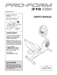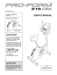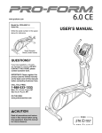
1
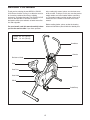
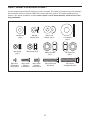
www.weslo.com
Model No. WLEX61211.0
Serial No.
Write the serial number in the
space above for reference.
Serial
Number
Decal
QUESTIONS?
If you have questions, or if parts are
damaged or missing, DO NOT
CONTACT THE STORE; please
contact Customer Care.
IMPORTANT: Please register this
product (see the limited warranty
on the back cover of this manual)
before contacting Customer Care.
1-866-699-3756
CALL TOLL-FREE:
Mon.–Fri., 6 a.m.–6 p.m. MT
Sat. 8 a.m.–4 p.m. MT
ON THE WEB:
www.wesloservice.com
CAUTION
Read all precautions and instructions in this manual before using
this equipment. Keep this manual
for future reference.
USERʼS MANUAL
TABLE OF CONTENTS
WARNING DECAL PLACEMENT . . . . . . . . . . . . . . . . . . . . . . . . . . . . . . . . . . . . . . . . . . . . . . . . . . . . . . . . . . . . . .2
IMPORTANT PRECAUTIONS . . . . . . . . . . . . . . . . . . . . . . . . . . . . . . . . . . . . . . . . . . . . . . . . . . . . . . . . . . . . . . . .3
BEFORE YOU BEGIN . . . . . . . . . . . . . . . . . . . . . . . . . . . . . . . . . . . . . . . . . . . . . . . . . . . . . . . . . . . . . . . . . . . . . .4
PART IDENTIFICATION CHART . . . . . . . . . . . . . . . . . . . . . . . . . . . . . . . . . . . . . . . . . . . . . . . . . . . . . . . . . . . . . .5
ASSEMBLY . . . . . . . . . . . . . . . . . . . . . . . . . . . . . . . . . . . . . . . . . . . . . . . . . . . . . . . . . . . . . . . . . . . . . . . . . . . . . . .6
HOW TO USE THE EXERCISE BIKE . . . . . . . . . . . . . . . . . . . . . . . . . . . . . . . . . . . . . . . . . . . . . . . . . . . . . . . . .11
FCC INFORMATION . . . . . . . . . . . . . . . . . . . . . . . . . . . . . . . . . . . . . . . . . . . . . . . . . . . . . . . . . . . . . . . . . . . . . . .13
MAINTENANCE AND TROUBLESHOOTING . . . . . . . . . . . . . . . . . . . . . . . . . . . . . . . . . . . . . . . . . . . . . . . . . . .14
EXERCISE GUIDELINES . . . . . . . . . . . . . . . . . . . . . . . . . . . . . . . . . . . . . . . . . . . . . . . . . . . . . . . . . . . . . . . . . . .15
PART LIST . . . . . . . . . . . . . . . . . . . . . . . . . . . . . . . . . . . . . . . . . . . . . . . . . . . . . . . . . . . . . . . . . . . . . . . . . . . . . .18
EXPLODED DRAWING . . . . . . . . . . . . . . . . . . . . . . . . . . . . . . . . . . . . . . . . . . . . . . . . . . . . . . . . . . . . . . . . . . . .19
ORDERING REPLACEMENT PARTS . . . . . . . . . . . . . . . . . . . . . . . . . . . . . . . . . . . . . . . . . . . . . . . . . .Back Cover
LIMITED WARRANTY . . . . . . . . . . . . . . . . . . . . . . . . . . . . . . . . . . . . . . . . . . . . . . . . . . . . . . . . . . . . . .Back Cover
WARNING DECAL PLACEMENT
This drawing shows the location(s) of the
warning decal(s). If a decal is missing or
illegible, see the front cover of this
manual and request a free replacement
decal. Apply the decal in the location
shown. Note: The decal(s) may not be
shown at actual size.
WESLO is a registered trademark of ICON IP, Inc.
2
IMPORTANT PRECAUTIONS
WARNING:
To reduce the risk of serious injury, read all important precautions and
instructions in this manual and all warnings on your exercise bike before using your exercise bike.
ICON assumes no responsibility for personal injury or property damage sustained by or through the
use of this product.
9. Wear appropriate clothes while exercising;
do not wear loose clothes that could become
caught on the exercise bike. Always wear
athletic shoes for foot protection.
1. Before beginning any exercise program,
consult your physician. This is especially
important for persons over age 35 or persons with pre-existing health problems.
10. The exercise bike should not be used by
persons weighing more than 250 lbs.
(113 kg).
2. Use the exercise bike only as described in
this manual.
3. It is the responsibility of the owner to ensure
that all users of the exercise bike are adequately informed of all precautions.
11. The heart rate monitor is not a medical
device. Various factors, including the user's
movement, may affect the accuracy of heart
rate readings. The heart rate monitor is
intended only as an exercise aid in determining heart rate trends in general.
4. The exercise bike is intended for home use
only. Do not use the exercise bike in a commercial, rental, or institutional setting.
12. When adjusting the seat, insert the seat
knob into one of the holes in the seat post.
Do not insert the seat knob under the seat
post.
5. Keep the exercise bike indoors, away from
moisture and dust. Do not put the exercise
bike in a garage or covered patio, or near
water.
13. The exercise bike does not have a free
wheel; the pedals will continue to move until
the flywheel stops. Reduce your pedaling
speed in a controlled way.
6. Place the exercise bike on a level surface
with at least 2 ft. (0.6 m) of clearance around
the exercise bike. To protect the floor or
carpet from damage, place a mat under the
exercise bike.
14. Always keep your back straight while using
the exercise bike; do not arch your back.
7. Inspect and properly tighten all parts regularly. Replace any worn parts immediately.
15. Over exercising may result in serious injury
or death. If you feel faint or if you experience
pain while exercising, stop immediately and
cool down.
8. Keep children under age 12 and pets away
from the exercise bike at all times.
3
BEFORE YOU BEGIN
Thank you for selecting the new WESLO® CROSS
CYCLE exercise bike. Cycling is an effective exercise
for increasing cardiovascular fitness, building
endurance, and toning the body. The CROSS CYCLE
exercise bike provides a selection of features
designed to make your workouts at home more effective and enjoyable.
after reading this manual, please see the front cover
of this manual. To help us assist you, note the product
model number and serial number before contacting
us. The model number and the location of the serial
number decal are shown on the front cover of this
manual.
Before reading further, please review the drawing
below and familiarize yourself with the labeled parts.
For your benefit, read this manual carefully before
you use the exercise bike. If you have questions
Length: 3 ft. 3 in. (99 cm)
Width: 1 ft. 9 in. (53 cm)
Handlebar
Console
Resistance Knob
Seat
Flywheel
Seat Post
Seat Knob
Shield
Pedal/Strap
4
PART IDENTIFICATION CHART
Use the drawings below to identify small parts used in assembly. The number in parentheses by each drawing is
the key number of the part, from the PART LIST near the end of this manual. The number following the key
number is the quantity needed for assembly. Note: If a part is not in the hardware kit, check to see if it has
been preattached.
M8 Washer
(38)–2
M6 Locknut
(56)–4
M5 x 6mm
Self-tapping
Screw (15)–7
M8 Split
Washer (8)–4
M8 Locknut (9)–8
M5 x 15mm
Machine
Screw (58)–1
M6 x 10mm
Machine
Screw (25)–4
M8 Curved
Washer (14)–2
Right Pedal Nut
(47)–1
M6 x 33mm Hex
Bolt (32)–4
5
1/2" Washer
(44)–2
Left Pedal Nut
(48)–1
M8 x 40mm
Carriage Bolt (18)–2
ASSEMBLY
• To hire an authorized service technician
to assemble the exercise bike, call
1-800-445-2480.
• In addition to the included tool(s), assembly
requires the following tools:
one Phillips screwdriver
• Assembly requires two persons.
one adjustable wrench
• Place all parts in a cleared area and remove the
packing materials. Do not dispose of the packing
materials until you complete all assembly steps.
Assembly will be more convenient if you have a
socket set, a set of open-end or closed-end
wrenches, or a set of ratchet wrenches. To avoid
damaging parts, do not use power tools for
assembly.
• To identify small parts, see page 5.
1. Turn the Rear Stabilizer (2) so that the slot
faces downward, and insert the Rear Stabilizer
into the Frame (1).
1
Attach the Rear Stabilizer (2) with four M6 x
10mm Machine Screws (25).
25
1
2
Slot
6
2. Turn the Front Stabilizer (5) so that the square
holes are facing away from the saddle bracket
on the Frame (1).
2
Attach the Front Stabilizer (5) with two M8 x
40mm Carriage Bolts (18), two M8 Curved
Washers (14), and two M8 Locknuts (9).
9
Square
Holes
3. Identify the Left Upper Handlebar (40) and the
left Lower Handlebar (57), which are marked
with “Left” stickers, and orient them as shown.
Make sure that the hexagonal holes are in
the indicated position.
14
1
5
18
3
Insert the Left Upper Handlebar (40) into the left
Lower Handlebar (57).
40
Attach the Left Upper Handlebar (40) with two
M6 x 33mm Hex Bolts (32) and two M6
Locknuts (56). Make sure that the Locknuts
are inside the hexagonal holes.
41
Repeat this step for the Right Upper
Handlebar (41) and the right Lower
Handlebar (57).
32
56
Hexagonal
Holes
57
7
32
57
4. Remove all parts from the Pivot Axle (3).
4
Using a small plastic bag to keep your fingers
clean, apply some of the included grease to the
Pivot Axle (3) and to the indicated locations.
40
Insert the Pivot Axle (3) into the Frame (1), and
align the hole in the center of the Pivot Axle with
the hole in the center of the Frame. Then,
tighten an M5 x 16mm Machine Screw (58) into
the Frame and the Pivot Axle.
50
Slide the Left and Right Upper Handlebars (40,
41) onto the ends of the Pivot Axle (3).
9
38
3
Grease
Next, slide an M8 Washer (38) onto each end of
the Pivot Axle (3), and tighten an M8 Locknut
(9) onto each end of the Pivot Axle at the same
time. Make sure that at least two threads on
each end of the Pivot Axle extend past each
Locknut. In addition, make sure that the
Upper Handlebars (40, 41) move freely.
41
1 58 Grease
38
9
50
Grease
Next, press a Pivot Cap (50) onto each end of
the Pivot Axle (3).
5. The Console (7) can use four AA batteries (not
included); alkaline batteries are recommended.
Do not use old and new batteries together or
alkaline, standard, and rechargeable batteries
together. IMPORTANT: If the Console has
been exposed to cold temperatures, allow it
to warm to room temperature before inserting batteries. Otherwise, you may damage
the console displays or other electronic
components. Remove the battery cover from
the back of the console, and insert batteries into
the battery compartment. Make sure to orient
the batteries as shown by the diagram inside
the battery compartment. Then, reattach the
battery cover.
5
7
Battery
Compartment
8
6. See the inset drawing. Orient the Console (7)
and the Console Bracket (52) as shown, and
insert the wire on the Console through the
Console Bracket. Attach the Console Bracket to
the Console with four M5 x 6mm Self-tapping
Screws (15).
6
7
7
While a second person holds the Console (7)
near the Frame (1), connect the wire on the
Console to the Reed Switch Wire (28).
28
Insert the excess wire into the Console (7).
1
Wire
52
15
7. Tip: Avoid pinching the wires. Press the
Console Bracket (52) onto the center of the
Frame (1). Attach the Console Bracket with
three M5 x 6mm Self-tapping Screws (15).
7
Avoid pinching
the wires
15
52
15
9
1
8. Attach the Seat (11) to the Seat Post (10) with
four M8 Locknuts (9) and four M8 Split Washers
(8). Note: The Locknuts and Split Washers may
be preattached to the Seat.
8
11
Next, insert the Seat Post (10) into the Frame
(1).
Align one of the adjustment holes in the Seat
Post (10) with the hole in the Frame (1).
10
8
Insert the Seat Knob (31) into the Frame (1)
and the Seat Post (10). Make sure that the
Seat Knob is inserted into one of the adjustment holes in the Seat Post; do not insert
the Seat Knob under the Seat Post. Then,
tighten the Seat Knob into the Frame.
8
9
9
Adjustment
Holes
Hole
1
31
9. Identify the Right Pedal (22), which is marked
with an “R.” Remove only the Right Pedal Nut
(47) and the Pedal Bushing (46) from the Right
Pedal.
9
Next, slide a 1/2" Washer (44) onto the shaft of
the Right Pedal (22), and insert the shaft into
the right Pedal Arm (49). Then, orient the Pedal
Bushing (46) as shown, slide it onto the shaft of
the Right Pedal, and insert it into the Pedal Arm.
21
Tighten the shaft of the Right Pedal (22) clockwise into the right arm of the Crank (20) as
firmly as possible. Then, tighten the Right Pedal
Nut (47) clockwise onto the shaft. Tighten the
Right Pedal and the Right Pedal Nut as
firmly as possible.
47
Repeat this step to attach the Left Pedal (21),
turning the Left Pedal and the Left Pedal Nut
(not shown) counterclockwise.
20
46
49
44
22
10. Make sure that all parts are properly tightened before you use the exercise bike. Note: Some hardware may be left over after assembly is completed. Place a mat under the exercise bike to protect the
floor or carpet from damage.
10
HOW TO USE THE EXERCISE BIKE
HOW TO ADJUST THE HEIGHT OF THE SEAT
FEATURES OF THE CONSOLE
For effective exercise, the seat should be at the
proper height. As you pedal, there should be a slight
bend in your knees when the pedals are in the lowest
position.
The console offers a selection of features designed to
make your workouts more effective. As you pedal, the
console will provide continuous exercise feedback.
To adjust the seat,
first loosen the seat
knob a few turns.
Seat
Next, pull the knob
outward, slide the
seat post upward or
Seat
downward to the
Post
desired position,
and then release
Seat Knob
the knob into one of
the adjustment
holes in the seat
post. Move the
seat post upward
or downward slightly to make sure that the knob is
engaged in one of the adjustment holes in the seat
post. Then, tighten the knob.
HOW TO ADJUST THE PEDALING RESISTANCE
To vary the intensity
of your exercise,
the pedaling resistance can be
adjusted. To
increase the resistance, turn the
resistance knob
clockwise; to
decrease the
resistance, turn the
knob counterclockwise.
Resistance
Knob
Before using the console, make sure that batteries are
installed (see assembly step 5 on page 8). If there is a
sheet of plastic on the display, remove the plastic.
HOW TO USE THE PEDALS
To use the pedals (see the drawing on page 4), insert
your shoes under the straps. Adjust the straps on the
pedals to the desired position, and press the ends of
the straps onto the tabs on the pedals.
11
HOW TO USE THE CONSOLE
To select the
speed, time,
distance, or
calories mode
for continuous
display, press
the Display
Mode button
repeatedly. An
indicator will show which mode is selected. Make
sure that there is not an indicator below the word
Scan.
1. Turn on the console.
To turn on the console, press the Display Mode button or begin pedaling. The display will turn on for a
moment; the console will then be ready for use.
2. Follow your progress with the display.
The display can show the following workout
information:
RPM—The RPM meter on the left side of the display indicates your approximate pedaling pace
(revolutions per minute).
The console can show speed and distance in either
miles or kilometers. The letters “mph” or “km/h” will
appear in the display to show which unit of measurement is selected.
Speed—This mode shows your pedaling speed, in
miles per hour (mph) or kilometers per hour (km/h).
To change the unit of measurement, first hold down
the Display Mode button for a few seconds. The
newly selected unit of measurement will appear in
the display. Repeat this action to change the unit of
measurement again.
Time—This mode shows the elapsed time.
Distance—This mode shows the distance you have
pedaled, in miles or kilometers.
Note: When the batteries are replaced, it may be
necessary to reselect the desired unit of
measurement.
Calories—This mode shows the approximate number of calories you have burned.
Scan—This mode shows the speed, time, distance,
and calories modes, for a few seconds each, in a
repeating cycle.
To pause the console, stop pedaling. If the time is
displayed, it will flash. To continue your workout,
simply resume pedaling.
3. When you are finished exercising, the console
will turn off automatically.
When you turn
on the power,
Indicators
the scan mode
will be selected
automatically.
One indicator
will appear
below the word
Scan to show
that the scan
mode is
selected, and a second indicator will show which
information is currently displayed. Note: If you have
selected a different mode, press the Display Mode
button repeatedly to reselect the Scan mode.
If the pedals do not move for a few seconds, the
console will pause. If the pedals do not move for a
few minutes, the console will turn off and the display will be reset.
12
FCC INFORMATION
This equipment has been tested and found to comply with the limits for a Class B digital device, pursuant to Part
15 of the FCC Rules. These limits are designed to provide reasonable protection against harmful interference in
a residential installation. This equipment generates, uses, and can radiate radio frequency energy and, if not
installed and used in accordance with the instructions, may cause harmful interference to radio communications.
However, there is no guarantee that interference will not occur in a particular installation. If this equipment does
cause harmful interference to radio or television reception, which can be determined by turning the equipment
off and on, try to correct the interference by one of the following measures:
•
•
•
•
Reorient or relocate the receiving antenna.
Increase the separation between the equipment and the receiver.
Connect the equipment to an outlet on a circuit different from the circuit to which the receiver is connected.
Consult the dealer or an experienced radio/TV technician for help.
FCC CAUTION: To assure continued compliance, use only shielded interface cables when connecting to
computer or peripheral devices. Changes or modifications not expressly approved by the party responsible for compliance could void the user's authority to operate this equipment.
13
MAINTENANCE AND TROUBLESHOOTING
HOW TO ADJUST THE RESISTANCE STRAP
Inspect and properly tighten all parts of the exercise
bike regularly. Replace any worn parts immediately.
If there is not enough pedaling resistance when the
resistance knob is turned to the highest setting, the
resistance strap may need to be adjusted.
To clean the exercise bike, use a damp cloth and a
small amount of mild soap. IMPORTANT: To avoid
damage to the console, keep liquids away from
the console and keep the console out of direct
sunlight.
To adjust the
resistance
strap, first turn
Slotted
the resistance
Tab
knob counterResistance
clockwise to
Strap
the lowest setting. Next,
locate the slotted tab on the
front of the
exercise bike. Grip the longest part of the resistance
strap underneath the slotted tab and pull it towards the
slot. When a little slack is created, pull the end of the
resistance strap tight. Turn the crank for a moment to
make sure that there is not too much resistance.
BATTERY REPLACEMENT
Most console problems are the result of low batteries.
To replace the batteries, see assembly step 5 on
page 8.
HOW TO TIGHTEN THE CRANK
If the arms of
the crank
become loose,
they should be
tightened in
Slotted
order to preCrank
Crank
vent excessive
Nut
Nut
wear. Loosen
the crank nut
on the left arm
Crank
of the crank.
Arm
Place the end
of a standard
screwdriver in one of the slots in the slotted crank nut.
Lightly tap the screwdriver with a hammer to turn the
slotted crank nut counterclockwise until the arms are
no longer loose. Do not overtighten the slotted
crank nut. When the slotted crank nut is properly
tightened, retighten the crank nut.
HOW TO ADJUST THE CHAIN
The exercise bike features a chain that must be kept
properly adjusted. If the chain causes excessive noise
or slips as you pedal, the chain should be adjusted.
To tighten the
chain, loosen,
but do not
remove, the
axle nuts on
both sides of
the flywheel.
Pull the flywheel forward
slightly. Make
sure that the
flywheel is
straight and
retighten the axle nuts.
14
Axle
Nut
EXERCISE GUIDELINES
WARNING:
Aerobic Exercise—If your goal is to strengthen your
cardiovascular system, you must perform aerobic
exercise, which is activity that requires large amounts
of oxygen for prolonged periods of time. For aerobic
exercise, adjust the intensity of your exercise until
your heart rate is near the highest number in your
training zone.
Before beginning this
or any exercise program, consult your physician. This is especially important for persons
over age 35 or persons with pre-existing
health problems.
HOW TO MEASURE YOUR HEART RATE
These guidelines will help you to plan your exercise
program. For detailed exercise information, obtain a
reputable book or consult your physician. Remember,
proper nutrition and adequate rest are essential for
successful results.
To measure your heart
rate, exercise for at
least four minutes.
Then, stop exercising
and place two fingers on
your wrist as shown.
Take a six-second heartbeat count, and multiply
the result by 10 to find your heart rate. For example, if
your six-second heartbeat count is 14, your heart rate
is 140 beats per minute.
EXERCISE INTENSITY
Whether your goal is to burn fat or to strengthen your
cardiovascular system, exercising at the proper intensity is the key to achieving results. You can use your
heart rate as a guide to find the proper intensity level.
The chart below shows recommended heart rates for
fat burning and aerobic exercise.
WORKOUT GUIDELINES
Warming Up—Start with 5 to 10 minutes of stretching
and light exercise. A warm-up increases your body
temperature, heart rate, and circulation in preparation
for exercise.
Training Zone Exercise—Exercise for 20 to 30 minutes with your heart rate in your training zone. (During
the first few weeks of your exercise program, do not
keep your heart rate in your training zone for longer
than 20 minutes.) Breathe regularly and deeply as you
exercise—never hold your breath.
To find the proper intensity level, find your age at the
bottom of the chart (ages are rounded off to the nearest ten years). The three numbers listed above your
age define your “training zone.” The lowest number is
the heart rate for fat burning, the middle number is the
heart rate for maximum fat burning, and the highest
number is the heart rate for aerobic exercise.
Cooling Down—Finish with 5 to 10 minutes of
stretching. Stretching increases the flexibility of your
muscles and helps to prevent post-exercise problems.
EXERCISE FREQUENCY
Burning Fat—To burn fat effectively, you must exercise at a low intensity level for a sustained period of
time. During the first few minutes of exercise, your
body uses carbohydrate calories for energy. Only after
the first few minutes of exercise does your body begin
to use stored fat calories for energy. If your goal is to
burn fat, adjust the intensity of your exercise until your
heart rate is near the lowest number in your training
zone. For maximum fat burning, exercise with your
heart rate near the middle number in your training
zone.
To maintain or improve your condition, complete three
workouts each week, with at least one day of rest
between workouts. After a few months of regular exercise, you may complete up to five workouts each
week, if desired. Remember, the key to success is to
make exercise a regular and enjoyable part of your
everyday life.
15
SUGGESTED STRETCHES
The correct form for several basic stretches is shown at the right. Move slowly as you stretch—never bounce.
1. Toe Touch Stretch
1
Stand with your knees bent slightly and slowly bend forward from
your hips. Allow your back and shoulders to relax as you reach
down toward your toes as far as possible. Hold for 15 counts, then
relax. Repeat 3 times. Stretches: Hamstrings, back of knees and
back.
2. Hamstring Stretch
2
Sit with one leg extended. Bring the sole of the opposite foot
toward you and rest it against the inner thigh of your extended leg.
Reach toward your toes as far as possible. Hold for 15 counts,
then relax. Repeat 3 times for each leg. Stretches: Hamstrings,
lower back and groin.
3. Calf/Achilles Stretch
With one leg in front of the other, reach forward and place your
hands against a wall. Keep your back leg straight and your back
foot flat on the floor. Bend your front leg, lean forward and move
your hips toward the wall. Hold for 15 counts, then relax. Repeat 3
times for each leg. To cause further stretching of the achilles tendons, bend your back leg as well. Stretches: Calves, achilles
tendons and ankles.
3
4
4. Quadriceps Stretch
With one hand against a wall for balance, reach back and grasp
one foot with your other hand. Bring your heel as close to your
buttocks as possible. Hold for 15 counts, then relax. Repeat 3
times for each leg. Stretches: Quadriceps and hip muscles.
5. Inner Thigh Stretch
Sit with the soles of your feet together and your knees outward.
Pull your feet toward your groin area as far as possible. Hold for
15 counts, then relax. Repeat 3 times. Stretches: Quadriceps and
hip muscles.
16
5
NOTES
17
PART LIST
Key No. Qty.
1
2
3
4
5
6
7
8
9
10
11
12
13
14
15
16
17
18
19
20
21
22
23
24
25
26
27
28
29
30
31
1
1
1
1
1
2
1
4
10
1
1
1
2
2
14
1
1
2
1
1
1
1
1
1
4
1
1
1
2
1
1
Description
Key No. Qty.
Frame
Rear Stabilizer
Pivot Axle
Frame Bushing
Front Stabilizer
Leveling Cap
Console
M8 Split Washer
M8 Locknut
Seat Post
Seat
Right Shield
Bronze Bushing
M8 Curved Washer
M5 x 6mm Self-tapping Screw
Flywheel
Resistance Strap
M8 x 40mm Carriage Bolt
Crank Bearing Assembly
Crank
Left Pedal/Strap
Right Pedal/Strap
Chain
Resistance Cable/Knob
M6 x 10mm Machine Screw
Flywheel Axle
3/8" Nut
Reed Switch/Wire
3/8" Flange Nut
M5 x 20mm Screw
Seat Knob
32
33
34
35
36
37
38
39
40
41
42
43
44
45
46
47
48
49
50
51
52
53
54
55
56
57
58
*
*
*
4
4
1
1
2
2
2
2
1
1
2
6
2
1
2
1
1
2
2
1
1
1
1
2
4
2
1
–
–
–
Model No. WLEX61211.0 R0112A
Description
M6 x 33mm Hex Bolt
M10 Washer
Resistance Spring
Sprocket
M8 x 43mm Hex Bolt
Pedal Arm Bushing
M8 Washer
Round Cap
Left Upper Handlebar
Right Upper Handlebar
Foam Grip
Pivot Bushing
1/2" Washer
Left Shield
Pedal Bushing
Right Pedal Nut
Left Pedal Nut
Pedal Arm
Pivot Cap
Clamp
Console Bracket
Resistance Control Housing
3/8" Jam Nut
Handlebar Cap
M6 Locknut
Lower Handlebar
M5 x 16mm Machine Screw
Userʼs Manual
Assembly Tool
Grease Packet
Note: Specifications are subject to change without notice. For information about ordering replacement parts, see
the back cover of this manual. *These parts are not illustrated.
18
EXPLODED DRAWING
Model No. WLEX61211.0 R0112A
29
15
45
15
26
54
16
42
40
12
13
55
7
27
11
13
9
50
10
8
9
38
15
8
9
36
49
57
41
43
3
43
53
33
33
37
43
9
1
15
46
34
15
28
4
44
42
58
43
56
30 24
32
55
52
32
8
9
21
43
8
9
15
43
51
6
14
15
19
38
9
56
14
31
32
5
25
17
19
48
15
39
2
29
18
20
9
23
57
6
37
33
49
35
33
47
39
46
19
44
22
36
9
50
ORDERING REPLACEMENT PARTS
To order replacement parts, please see the front cover of this manual. To help us assist you, be prepared to
provide the following information when contacting us:
• the model number and serial number of the product (see the front cover of this manual)
• the name of the product (see the front cover of this manual)
• the key number and description of the replacement part(s) (see the PART LIST and the EXPLODED
DRAWING near the end of this manual)
LIMITED WARRANTY
IMPORTANT: You must register this product within 30 days of the purchase date to avoid added
fees for service needed under warranty. Go to www.wesloservice.com/registration.
ICON Health & Fitness, Inc. (ICON) warrants this product to be free from defects in workmanship and
material, under normal use and service conditions. Parts and labor are warranted for ninety (90) days from
the date of purchase.
This warranty extends only to the original purchaser (customer). ICONʼs obligation under this warranty is
limited to repairing or replacing, at ICONʼs option, the product through one of its authorized service centers. All repairs for which warranty claims are made must be preauthorized by ICON. If the product is
shipped to a service center, freight charges to and from the service center will be the customerʼs responsibility. If replacement parts are shipped while the product is under warranty, the customer will be
responsible for a minimal handling charge. For in-home service, the customer will be responsible for a
minimal trip charge. This warranty does not extend to freight damage to the product. This warranty will
automatically be voided if the product is used as a store display model, if the product is purchased or
transported outside the USA, if all instructions in this manual are not followed, if the product is abused or
improperly or abnormally used, or if the product is used for commercial or rental purposes. No other warranty beyond that specifically set forth above is authorized by ICON.
ICON is not responsible or liable for indirect, special, or consequential damages arising out of or in connection with the use or performance of the product; damages with respect to any economic loss, loss of
property, loss of revenues or profits, loss of enjoyment or use, or costs of removal or installation; or other
consequential damages of any kind. Some states do not allow the exclusion or limitation of incidental or
consequential damages. Accordingly, the above limitation may not apply to the customer.
The warranty extended hereunder is in lieu of any and all other warranties, and any implied warranties of
merchantability or fitness for a particular purpose are limited in their scope and duration to the terms set
forth herein. Some states do not allow limitations on how long an implied warranty lasts. Accordingly, the
above limitation may not apply to the customer.
This warranty provides specific legal rights; the customer may have other rights that vary from state to state.
ICON Health & Fitness, Inc., 1500 S. 1000 W., Logan, UT 84321-9813
Part No. 316113 R0112A
Printed in China © 2011 ICON IP, Inc.