1
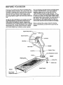
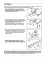
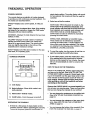
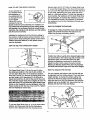
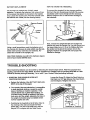
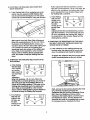
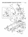
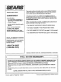
VVE._L(_)®
"rM
cardioVVALK
SW/AR6
USER'S MANUAL
Model No. 831.150191
Serial No.
The serial number can be foundin the
locationshownbelow. Writethe serial
numberin the space above.
Serial Number Decal
/
EQUIPMENT
[o|
Ii
:ll_9
Ill
NoB
_ |1
HELPLINE!
e#__,_,_
(..7, L/ tJ-
-,o#.
/ _. v
5870.
.
US PATENT 5,102,380
US PATENT 5,282,776
SEARS, ROEBUCK AND CO., HOFFMAN ESTATES, IL 60179
TABLE
OF CONTENTS
IMPOR_TANT PRECAUTIONS
.............................................................
BEFOI_E YOU BEGIN ...................................................................
ASSEMBLY ...........................................................................
TREADMILL OPERATION ................................................................
TROUBLE-SHOOTING
..................................................................
CONDITIONING GUIDELINES .............................................................
PART LIST ...........................................................................
EXPLODED DRAWING .................................................................
ORDERING REPLACEMENT PARTS ................................................
FULL 90 DAY WARRANTY
.......................................................
2
2
3
4
5
7
9
10
11
Back Cover
Back Cover
BEFORE YOU BEGIN
Thank you for selecting the WESLO" CARDIO WALK
Dual Motion Manual Treadmill. The natural, motion and
versatility of treadmills have made them the most popular way to get an effective cardiovascular workout.
With the dual motion design of the CARDIO WALK,
you can get both an upper- and lower-body workout as
well.
To help you stay motivated as you exercise, the CARDIO WALK features an electronic console that provides continuous feedback of speed, elapsed time,
total distance, and the approximate number of Calodes
you have burned. And the adjustability of the CARDIO
WALK allows you to work at your own level, whether
you are just beginning or already exercise regularly.
For your benefit, read this manual carefully before
using the CARDIO WALK. If you have additional
questions, please call our toll-free HELPLINE at
1-800-736-6879, Monday through Saturday, 7 a.m.
until 7 p.m. Central Time (excluding holidays). To help
us assist you, please note the product model number
and serial number before calling. The model number is
831.150191. The serial number can be found on a
decal attached to the CARDIO WALK (see the front
cover of this manual to find the location of the decal).
Before reading further, please review the drawing
below and familiarize yourself with the parts that are
labeled.
Hil:
Cotter
Lock Pin
; Control
FRONT
Walking
Pin
Leg
RIGHT SIDE
BACK
Rear Roller
Adjustment
ASSEMBLY
Set the CARDIO WALK in a cleared area and remove all packing materials. Do not dispose of the packing materials until assembly is completed. Assembly requires
the Included
1. Raise the Upright (10) to the vertical position. Slide the
Smell Upright Washer (79) and the Large Upright Washer
(25) onto the Upright Bolt (24). "13ghtenthe Upright Bolt into
the Upright with the Allen Wrench (53).
allen wrench
_
1
°o
2. Insert an Incline Leg (9) into one of the adjustment posts on
the Frame (37). Align one of the holes in the Incline Leg with
the hole in the adjustment post. Insert an Incline Pin (26)
through the adjustment post and the Incline Leg.
Assemble the other Incline Leg (9) in the same manner,
Make sure that both Incline Legs are at the same height.
9
Adjustment
Post
26
3. Attach the Hip Pad Bracket (72) to the Upright (10) with the
Pad Knob (52) and Knob Washer (36). (The three holes in
the Upright are for height adjustment. Select the height that
is the most comfortable.) Be sure that the Hip Pad (33) is
• oriented as shown.
3
33
72
36
4. Remove the paper backing from the Wrench Clip (50).
Attach the Wrench Clip to the underside of the Frame (37)
as shown, Slide the Allen Wrench (53) into the Wrench Clip,
37
5O
Because there are moving parts on the underside of the treadmill, it Is recommended that you cover the
floor beneath the treadmill. Your treadmill features a walking belt coated with PERFORMANT LUBE TM, a highperformance lubricant. IMPORTANT: Never apply silicone spray or other substances to the walking belt or
the walking platform. They will deteriorate the walking belt and cause excessive wear.
4
TREADMILL
OPERATION
CONSOLE MODES
The console features a selection of modes designed
to provide you with continuous exercise feedback. The
five modes are described below:
SPEED--Displays
hour.
simply begin walking. The entire display will appear
for two seconds; the console will then be ready for
operation.
2. Select one of the fwe modes:
your current speed, in miles per
SCAN mode--When the power is tumed on, the
SCAN mode will be selected automatically. One
mode indicator will show that the SCAN mode has
been selected, and a second mode indicator will
show which mode is currently displayed. The
SCAN mode can also be selected by repeatedly
pressing the mode button.
TIME--Displays the elapsed time. Note: If the walking
bolt stops for ten seconds or longer, the TIME mode
will pause until you resume walking.
DISTANCE---Displays the total distance that you have
walked, in miles.
:
SPEED, TIME, DISTANCE or CALORIE mode--
CALORIE---DISplays the total number of nutritional
calories you have burned. Note: The number displayed is an approximate figure. The actual number
may vary slightly depending on the incline of the
treadmill and the resistance settings.
SCAN--Displays all of the above modes, for five seconds each, in a repeating cycle.
These modes can be selected by repeatedly
pressing the mode button. A mode indicator will
show which mode has been selected. The modes
are selected in the following order: SPEED, TIME,
DISTANCE, CALORIE, and SCAN.
3. To reset the modes, turn the power off and then on
again by pressing the on/off button twice.
CONSOLE DIAGRAM
A
.
B
To rum off the power, press the on/off button. Note:
If the walking belt is not moved and the console
buttons are not pressed for four minutes, the power
will turn off automatically in order to conserve the
batteries.
HOW TO WALK ON THE TREADMILL
DIS'g_ICE CALORIES SCAN
Stand on the walking belt, hold the upper body arms,
and lean on the hip pad. (See HOW TO USE THE
UPPER BODY ARMS on page 6). Slowly begin walking on the treadmill. Use the upper body arms for balance and lean on the hip pad to =push off' when you
begin walking. Always hold the upper body arms
when getting on and off the treadmill, and when
exercising on the treadmill.
A. LCD display.
B. Mode indicators---Show which mode is currently selected.
Because the CARDIO WALK is a manual treadmill, you
can set your own exercise pace. There are three ways
that you can change the intensity of your workout:
C. Mode button--Selects modes.
•
You can change the resistance on the walking belt.
(See HOW TO USE THE SPEED CONTROL on
page 6.)
•
You can increase the resistance of the upper body
arms. (See HOW TO USE THE UPPER BODY
ARMS on page 6.)
•
You can increase the incline of the treadmill. (See
HOW TO CHANGE THE INCLINE on page 6.)
D. On/off button--Turns the power on and off.
OPERATING THE CONSOLE
1. If there is a thin piece of clear plastic on the
console, remove it before operating the console.
To turn on the power, press the on/off button or
HOWTOUSETHESPEED
CONTROL
As you exercise on
the CARDiO WALK,
the resistance on
the walking belt can
be changed by turning the Speed
Control (57) on the
Console (7). As the
Speed Control is turned clockwise, the resistance on
the walking belt will increase and your walking speed
will decrease. As the Speed Control is turned counterclockwise, the resistance wilt decrease and the walking
belt will move more freely.
Remove the Lock Pin (11) from the Upper Body Arms
(1,2) and the Upright (10). In the dual motion position,
you can move the Upper E_bdyArms forward and back
as you walk, exercising your arms, back and shoulders for a total body workout. To tailor the intensity of
your exercise, the resistance of the Upper Body Arms
can be changed. To increase the resistance, tum the
Arm Resistance Control (15) clockwise; to decrease
the resistance, turn the Arm Resistance Control counterclockwise.
HOW TO CHANGE THE INCLINE
To change the i,'w.line,first lift the front of the treadmill
slightly and remove the Incline Pin (26) from one
Incline Leg (9) (see the drawing below).
Adjusting the resistance from the minimum setting to
tl_ maximum setting requires several rotations of the
speed control. Stop turning the speed control when
rotatlon becomes difficult, or the speed control
may be damaged.
HOW TO USE THE UPPER BODY ARMS
Position the Incline Leg (9) at the desired height, align
one of the holes in the Incline Leg with the hole in the
adjustment pest, and insert the Incline Pin (26)
through the adjustment post and the Incline Leg.
Adjust the other Incline Leg in the same manner.
Make sure that the Incline Pins are fully inserted
and that both Incline Legs ere at the same height.
The Upper Body Arms (1, 2) can be used in either
the stationary position or the dual motion position. To
use the Upper Body Arms in the stationary position,
insert the Lock Pin (11) through the Upper Body Arms
an.dthe Updght (10). Important: If It is difficult to
insert the Lock Pin, do not hit the end of the Lock
Pin; twist the Upper Body Arms slightly in order to
align the holes. Do not twist the Upper Body Arms
too far or the treadmill may be damaged. Insert the
Hairpin Cotter (3) into the end of the Lock Pin. "13ghten
the Arm Resistance Control (15).
HOW TO ADJUST THE HIP PAD
For your comfort, the height of the Hip Pad (33) can
be adjusted (see the drawing below). There are three
height settings. To change the height setting, first
remove the Pad Knob (62) and Knob Washer (36).
Align the hole in the Hip Pad Extension (72) with the
desired hole in the Upright (10). Secure the Hip Pad
Bracket with the Pad Knob and Washer.
33
ent
To use the Upper Body Arms (1, 2) in the dual motion
position, first make sure that the Arm Resistance
Control (16) is tightened (see the drawing above).
6
BA'FrERYREPLACEMENT
HOW TO STORE THE TREADMILL
TheConsole(7) requirestwo "LR44"
To convert the treadmill to the storage position,
first turn the Arm Resistance.Control (15) counterclockwise until it tums freely (see the drawing
below). Failure to do so will result in damage to
the treadmill.
watch
batteries. To replace the batteries, first remove three
of the sorews that attach the Console to the Upright
(10). Loosen the fourth screw. Pivot the Console until
the batteries are visible (see the drawing below).
7_
2
Remove Screws
24
25
Loosen
45
Next, remove the Upright Bolt (24) and Upright Flat
Washer (25) from the Upright (10). Lay the Upright and
the Upper Body Arms (1, 2) on the Walking Belt (45).
Be careful not to pinch the sensor wire in the
tJprlghL Replace the Upright Bolt and Upright Flat
WasheHor storage.
Using a small screwdriver, push the batteries out of
the Console (7). Be sure to note which way the batterles were turned. Inse_t two new batteries. Reattach the Console to the Upright (10).
Note: Watch batteries are sold in the hardware depadment of your nearest SEARS store.
TROUBLE-SHOOTING
Most treadmill problems can be solved by following the simple steps below. Find the symptom that
applies, and follow the steps listed. If further assistance is needed, call our toll-free HOTUNE at 1-800736-6879, Monday through Saturday, 7 a.m. until 7 p.m. Central Time (excluding holidays).
1. SYMPTOM: THE CONSOLE DOES NOT
FUNCTiON PROPERLY
Loosen the Screw (5). Adjust the Reed Switch so
that there is a 1/8" gap between the Reed Switch
and the Magnet. Retighten the Screw.
a. Replace the batteries. (See BA'I-FERY REPLACEMENT at the top of this page.)
b. The console, like most electronics, is susceptible
to static electricity build-up, caused, by certain
types of clothing or machine operation. If the
console blanks out or gives false readings, an
anti-static spray should be applied to the upper
body arms and the upright, especially the base of
the upright. Anti-static spray is available where
laundry supplies are sold.
5
c. Carefully tip the treadmill on its left side. Refer to
the drawing at the right and locate the Reed
Switch (29). Turn the Front Roller (27) until the
Magnet (51) is aligned with the Reed Switch.
Underside of Treadmill
7
2.SYMPTOM:
THEWALKINGBELTDOESNOT
MOVESMOOTHLY
a.
Roller Adjustment Bolt (42) clockwise, and the
right Bolt counterclockwise, 1/4 of a turn each. Be
careful not to overtighten the Walking Belt. Walk
on the treadmill for a few minutes. Repeat until
the Walking Belt is centered.
If the Walking Belt (45) is ov'ert.ightened,performance may be reduced and- .t_ Walking Belt
may be permanently damaged. Turn the speed
control fully counterclockwise. Using the included
c. If the Walking
Belt (45) has
shifted to the
right side, use
the allen
wrench to turn
the left Rear
Roller
Adjustment Bolt (42) countemlockwise, and the
right Bolt clockwise, 1/4 of a turn each. Be careful not to overtighten the Walking Belt. Walk on
the treadmill for a few minutes. Repeat untilthe
Walking Belt is centered.
42
allen wrench, turn both Rear Roller Adjustment
Bolts (42) counterclockwise 1/4 of a turn. When
the tension of the Walking Belt is correct, you
should be able to lift each side of the walking belt
2 to 3 inches; the center of the Walking Belt
should just touch the surface of the walking platform. Walk on the treadmill for a few minutes.
4_ SYMPTOM: THE RESISTANCE ON THE WALKING BELT DOES NOT INCREASE WHEN THE
SPEED KNOB IS TURNED
a. If the resistance on the walking belt does not
increase when the speed knob is turned clockwise, the resistance belt should be tightened.
Repeat until the Walking Belt is propedy tightened. Be careful to keep the Walking Belt cantered.
3. SYMPTOM: THE WALKING
OFF-CENTER
To tighten the resistance belt, first tum the speed
control counterclockwise as far as it will tum.
BELT SLIPS OR IS
a. If the Walking
Belt (45) slips
when walked
on, use the
allen wrench to
turn both Rear
Roller
Adjustment
Belts (42) clockwise, 1/4 of a turn. When the
Walking Belt is correctly tightened, you should be
able to lift each side of the Walking Belt 2 to 3
inches off the walking platform. The center of the
Walking Belt should just touch the walking platform. Walk on the treadmill for a few minutes.
Repeat until the Walking Belt is properly tightened.
Be careful to keep the Walking Belt centered.
Next, remove the four screws attaching the Hood
(14). Remove the Hood and locate the
Resistance Belt (67) and the Resistance Clamp
(60). Open the Resistance Clamp, pull the
Resistance Belt slightlytighter, and firmly close
the Resistance Clamp. Turn the speed knob
clockwise and walk on the walking belt to check
for increased tension. Reattach the Hood.
b. If the Walking
Belt (45) has
shifted to the
left side, use
the allen
wrench to turn
the left Rear
8
CONDITIONING
GUIDELINES
The following guidelines will help you to plan your
exercise program. Remember that proper nutrition and
adequate rest are essential for successful results.
During the first few months of your exercise program,
keep your heart rate near the low end of your training
zone as you exercise. After a few months of regular
exercise, your heart rate can be increased gradually
until it is near the middle of your training zone as you
exercise. To measure
your heart rate, stop
exemising and place
two fingers on your
wdst. Take a six second
heartbeat count.
WHY EXERCISE?
Exemise has proven essential for good health and
general well-being. Regular participation in a wellrounded exercise program also results in a strcnger
and more efficient heart, improved respiratory function,
increased stamina and endurance, better weight management and body fat control, increased ability to deal
with stress, and greater self-esteem and confidence.
Multiply the result by
ten to find your heart
rate. (A six second
count is used because
your heart rate drops
quickly when you stop
exercising.) If your heart rate is too high, decrease the
intensity of your exemise. If your heart rate is too low,
increase the intensity of your exemise.
EXERCISE INTENSITY
To maximize the benefits of exemising, it is important
to exemise with the proper intensity. The proper intensity level can be found by using your heart rate as a
guide. For effective aerobic exercise, your heart rate
should be maintained at a level between 70% and
85% of your maximum heart rate as you exemise.
This is known as your training zone. You can find
your training zone in the table below. Training zones
are listed for both unconditioned and conditioned per.sons according to age.
TRAINING
ZONE (BEATS/MIN.)
AGE
UNCONDITIONED
CONDITIONED
20
138-167
133-162
25
136-166
132-160
30
138-164
130-158
35
134-162
129-156
40
132-161
127-155
45
131-159
126.153
50
129-156
124-150
55
127-155
122-149
60
126-153
121-147
65
125-151
119-145
70
123-150
118-144
75
122-147
117-142
80
120-146
115-140
85
118-144
114-139
WORKOUT GUIDELINES
A well-reunded workout includes the following three
phases:
A warm-up phase, lasting 5 to 10 minutes. Begin with
slow, controlled stretches, and progress to more rhythmic stretches to increase body temperature, heart rate,
and circulation in preparation for strenuous exercise.
A cardiovascular phase, including 20 to 30 minutes
of exercising with your heart rate in your training zone.
A cool-down phase, consisting of 5 to 10 minutes of
stretching. Thorough stretching offsets muscle contractions and other problems caused when you stop
exercising suddenly. Stretching for increased flexibility
is often most effective dudng this phase. This phase
should leave you relaxed and comfortably tired.
To maintain or imprOve your condition, complete three
workouts each week, with at least one day of rest
between workouts. After a few months of regular exercise, you may complete up to five workouts each
week, if desired. Whatever time you choose, be consistent and stick with it. Remember, the key to success is to make exercise a regular and enjoyable part.
of your everyday life.
PART LISTmModel
Key
No.
Part
No.
Qty.
1
2
3
4
5
6
7
8
9
10
11
126487
126548
015044
126034
013576
125328
127631
126547
127358
126549
121544
12
13
14
15
16
17
18
19
20
21
22
23
24
25
26
27
28
29
30
31
32
33
34
35
36
37
38
39
40
41
÷
No. 831.150191
Ros96A
Description
Key
No.
Part
No.
1
1
1
8
4
10
1
1
2
1
1
Left Upper Body Arm w/Foam
Right Upper Body Arm w/Foam
Hairpin Cotter
Platform Screw
Screw
#8 Finish Washer
Console
Walking Platform
Incline Leg
Upright
Lock Pin
42
43
44
45
46
47
48
49
50
51
52
013206
124993
125721
126551
121269
124987
014156
109265
016028
127188
017068
2
2
2
1
1
1
1
2
1
1
1
Rear Roller Adjustment Bolt
Adjustment Plate
Foam Gdp
Walking Belt
Friction Cover
Pivot Bolt
Control Washer
Belt Guide
Wrench Clip
Magnet
Pad Knob
129023
127669
126550
116693
110193
014087
126397
116673
125486
125705
125213
125214
013563
104188
122946
126388
126389
126937
045016
014088
125708
125467
128108
125191
105496
NSP
i:
2
1
1
2
2
2
2
2
10
2
4
1
1
2
1
1
1
2
1
1
1
1
1
1
1
Flywheel Shaft w/Hardware
Tension Spring
Hood
Arm Resistance Control
Friction Bracket
Washer
Upper Body Arm Housing
Friction Plate
Side Trim
#8 Flat Head Screw
Rear Foot
Rear Foot Screw
Upright Bolt
Large Upright Washer
Incline Pin
Front Roller
Rear Roller
Reed Switch/Sensor Wire
Small E-Ring
Star Washer
Cage Nut
Hip Pad
Flywheel w/Hardware
Flywheel Belt
Knob Washer
Frame
53
54
55
56
57
58
59
60
61
62
63
64
65
66
67
68
69
70
71
72
73
74
75
76
77
78
126040
016057
112013
125679
125355
016017
013162
050001
013326
012009
013009
014003
012003
105434
127633
012149
013399
052012
125468
125462
013505
014126
108080
120630
125823
130965
1
1
2
1
1
1
1
1
1
2
1
4
1
1
1
2
2
2
1
1
2
2
1
4
1
1
Allen Wrench
Cable Tie
Arm Cap
E-Ring
Speed Control
Cable Tie Clip
Resistance Clamp Screw
Resistance Clamp
Cable Adjustment Screw
Cable Adjustment Nut
Cable clamp Bolt
Cable Clamp Washer
Cable Clamp Nut
Resistance Spring
Resistance Belt
Incline Wheel Nut
Incline Wheel Bolt
Incline Wheel
Belt Resistance Cable
Hip Pad Extension
Hip Pad Boll
Hip Pad Washer
Reed Switch Screw
Belt Guide Screw
Roller Pushnut
Axle Washer
118332
108874
124964
124955
1
2
1
1
Reed Switch Extension
Frame Cap
LeftEndcap
Right Endcap
79
#
#
105495
118332
128076
1
1
1
Small Upright Washer
Reed Switch Extension Wire
User's Manual
Qty. Description
Note: "#" Indicates a non-illustrated part. Specifications are subject to change without notice. See the hack
cover of this manual for information about ordering replacement parts.
10
EXPLODED
DRAWINGmModel
No. 831.150191
RO596A
44
11
74
44
33
2
_7
17
31
46
79
7
16
.55
21
26
"_
32i
21
48
_
39
l
37
8
45
\
20
28
21
53
21
70
78
40
34
30
43
41
12
11
...J
69
26
The model number and serial number of your WESLO = CARDIO
WALK are listed on a decal attached to the frame. See the front
cover of this manual to find the lobation of the decal.
ModelNo.831.150191
QUESTIONS?
If you find that:
• you need help aseembllng or
operating the CARDIO WALK
All replacement parts are available for immediate purchase or
special order when you visit your nearest SEARS Service Center.
To request service or to order parts by telephone, call the toll-free
numbers listed at the left.
When requesting help or service, or ordering parts, please be prepared to provide the following information:
• a part is missing
• or you need to schedule repair
service
call our toll-free HELPLINE
• The NAME OF THE PRODUCT (WESLO e CARDIO WALK)
• The MODEL NUMBER OF THE PRODUCT (831.150191).
1-800-736-6879
Monday-Saturday, 7 am-7 pm
Central Time (excluding holidays)
• The PART NUMBER OFTHE
PART (see page 10 of this manual).
• The DESCRIPTION OF THE PART (see page 10 of this manual).
REPLACEMENT
PARTS
If parts become worn and need to
be replaced, call the following
toll-free number
1-800-FON-PART
(1-800-366-7278)
SEARS, ROEBUCK AND CO., HOFFMAN ESTATES, IL 60179 USA
•FULL 90 DAY •WARRANTY
]
For 90 days from the date of purchase, if failure occurs due to defect in material or workmanship in this
SEARS TREADMILL EXERCISER, contact the nearest SEARS Service Center throughout the United
States and SEARS will repair or replace the TREADMILL EXERCISER, free of charge.
This warranty does not apply when the TREADMILL EXERCISER is used commercially or for rental parposes.
This warranty gives you specific legal rights, and you may also have other rights which vary from state
to state.
SEARS, ROEBUCK AND CO., DEPT. 817WA, HOFFMAN ESTATES, IL 60179
Part No. 128076 F00627BC
R0596A
Printed in USA © 1996 Sears, Roebuck and Co.