1
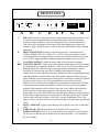
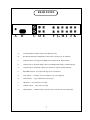
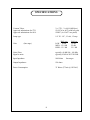
MANLEY
LABORATORIES, INC.
OWNER'S MANUAL
THE PURIST
PREAMPLIFIER
MANLEY LABORATORIES, INC.
13880 MAGNOLIA AVE.
CHINO, CA. 91710
TEL: (909) 627-4256
FAX: (909) 628-2482
email: [email protected]
http://www.manleylabs.com
CONTENTS
SECTION
PAGE
INTRODUCTION
3
MAINS CONNECTIONS
4
CONNECTING YOUR PREAMPLIFIER
5
FIGURE 1
FRONTPANEL
6
FIGURE 2
REAR PANEL
7
OPERATIONAL NOTES
8
SPECIFICATIONS
9
WARRANTY
10
WARRANTY REGISTRATION
11
INTRODUCTION
THANK YOU!...
for choosing the Manley Laboratories "The Purist Preamplifier". Designed by David Manley, the Purist
Preamplifier uses the best available parts with the shortest, cleanest, signal path possible. This Preamp
has all the vital signal conducting electronics located near the input / output jacks with the controls
connected with long shafts. The high-current line circuit employed here is one we have develop and
refined over the years in our MANLEY Professional series. Minimalist signal path is accomplished with
a few short, wide PC traces and very little wire. The signal wire is six nines pure copper, teflon insulated
and well shielded. The signal is direct coupled through the tube stages and is only passed through one
capacitor per side -and these are premium MIT foil/film caps . The gain controls are precise conductive
plastic pots with thw main volume being a custom unit specially imported that has superior electrical and
mechanical characteristics. These controls are a large part of why this preamp has such a musical appel
similar to precision passive preamps. While passive preamps are notoriously sensitive to interconnect
cables, this preamp will be easier and probably less costly to interface due to its constant low impedance
output and high impedance inputs. Finally (but really initially) the power supply is a simple, highly
filtered, well engineed design without the reliability problems common in other high voltages
supplies.
The elegant front panel finish is a high purity plated gold that complements the electronics both visually
and in its long lasting outstanding quality. We hope you agree with us and hundreds of satisfied users
and studios around the world that this preamp really delivers. Please take a few moments to read
through this manual, there may be features and information about this preamplifier which you should
familiarise yourself with.
Thank you again, and please enjoy!
GENERAL NOTES
LOCATION & VENTILATION
The Purist Preamplifier must be installed in a stable location with ample ventilation. It is recommended,
if this unit is rack mounted, that you allow enough clearance on the top and bottom of the preamp such
that a constant flow of air can flow through the ventilation slots. We also recommend that the
preamplifier be placed at least 10 inches away from its amplifier.
WATER & MOISTURE
As with any electrical equipment, this preamplifier should not be used near water or moisture.
SERVICING
The user should not attempt to service the preamplifier beyond that described in the owner's manual.
Refer all servicing other than tube replacement to Manley Laboratories.
SPECIAL NOTES
Tubes may become loose during transit. Straighten and press down each tube before plugging the
preamplifier into the mains socket. Furthermore, do not touch the tubes after the preamplifier has been
switched on, as the tubes do become very hot during operation and should only be handled after the
power has been turned off and the tubes have cooled.
3
MAINS CONNECTIONS
Your preamplifier has been factory set to the correct mains voltage for your country. The
voltage setting is marked on the serial badge, located on the rear panel. Check that this complies with your local supply.
Export units for certain markets have a moulded mains plug fitted to comply with local requirements. If your unit does not have a plug fitted the coloured wires should be connected to the
appropriate plug terminals in accordance with the following code.
GREEN/YELLOW
BLUE
BROWN
EARTH
NEUTRAL
LIVE
terminal
terminal
terminal
As the colours of the wires in the mains lead may not correspond with the coloured marking
identifying the terminals in your plug proceed as follows;
The wire which is coloured GREEN/YELLOW must be connected to the terminal in the plug
which is marked by the letter E or by the safety earth symbol or coloured GREEN or GREEN
and YELLOW.
The wire which is coloured BLUE must be connected to the terminal in the plug which is
marked by the letter N or coloured BLACK.
The wire which is coloured BROWN must be connected to the terminal in the plug which is
marked by the letter L or coloured RED.
DO NOT CONNECT/SWITCH ON THE MAINS SUPPLY UNTIL ALL OTHER CONNECTIONS HAVE BEEN MADE.
4
CONNECTING YOUR PREAMPLIFIER
Setting up your preamplifier is rather easy.
1. Please refer to page 7 diagram 2 for an illustration of the back of the preamplifier.
2. There are three sets of main outputs, two identical sets of UNBALANCED RCA
and the other BALANCED XLR. The BALANCED XLR's can be used with unbalanced
inputs and either "leg" can be shorted to ground with no ill effects. This output is 6 dB
louder than the unbalanced outputs because both "legs" contribute to the measured
output. The pin out for the XLR is as follows:
PIN1 - ground
PIN2 - POSITIVE going phase (+)
PIN3 - NEGATIVE going phase (-).
Connect either (or both for bi-amping) the XLR or RCA output to the input of your amplifier as required.
3. UNBALANCED inputs are found on RCA jack inputs and can be connected to any line
level sources such as CD players, tuners or tape decks.
4. All RCA jacks are clearly labelled as to a typical function. Each input is for all intents
other than the labels functionally and electronically the same.
5. The record output is not buffered and it is recommended that one have the tape feed
plugged into the REC OUT only when actually recording. Care should be used when
using a 3-head tape/monitor switch as this record out is not a tape loop.
6. On the left end of the back panel is a standard IEC mains connector. This should be
connected to a standard mains outlet with the supplied cable. This unit has been hardwired for the mains voltage in your country
7. Power up the preamplifier FIRST and allow it to settle for a minimum of 30 seconds
before powering up your amplifiers. Turn off your preamplifier and source components
LAST when powering down a system. This prevents amplification of turn-on transients
and other noises when powering up or turning a system off and ultimately protects the
speakers.
5
FRONT PANEL
SELECT
SET GAIN
BALANCE TRIM
VOLUME
L
R
AUX
TAPE
CD
TUNER
VIDEO
HIGH
MED
LOW
OPERATE
MANLEY
1
0
MUTE
VARIABLE FEEDBACK
A
B
C
D
A
E F
G
H
SET GAIN Switch to select general gain of the preamp to personal preferences. Due
to a lack of current standards of power amp and preamp sensitivity this feature
provides a simple method to scale the overall gain of the system or allow one to
reduce the power amp gain to reduce noise. Note that changing this switch can
introduce "pops" into the system - so MUTE the audio momentarily while changing
this control.
B
SELECTOR SWITCH Switch to select between inputs. Counterclockwise:
VIDEO, TUNER, DIG ,CD, TAPE, AUX,. NOTE: always turn volume control
(level) down before switching selector switch to avoid surprise differences in source
levels. NOTE: inputs which have nothing plugged in to them can pick up noise.
C
VOLUME CONTROL Adjust the stereo input level of the selected signal.
D&E BALANCE ADJUSTS These very useful controls modify the gain of each channel
by changing the line amplifier's feedback. When set to 12 o'clock (straight up) both
channels will produce the same gain at optimum setting. Rotating the controls
clockwise will increase the gain (lower feedback) and rotating the controls
counterclockwise will reduce the gain (more feedback) of the corresponding channels
with approximately 10 dB of total swing. Thus neither control will fully mute the
signal. Different sound characteristics can be achieved with these controls to optimise
the gain, speed, and slew rate of this preamplifier to your system, but small
differences of level between two channels can be equalled or trimmed out with these
controls when used as dual-mono balance controls. In some systems the optimum
setting of both controls is fully clockwise, thus, the least feedback. Musically this
tends to produce a subtly more aggressive, fast, punchy and more forward
presentation. In systems that already have this quality the optimum setting will likely
be from fully counterclockwise to a mid position. Some describe the more feedback
sound as more laid back, mellow or "tube-like" warmth. Experiment! There is no
right or wrong. Your taste will set these controls (maybe even differently for different
CD's!)
F
MUTE / OPERATE Toggle switch that provides a simple cut or mute to the audio
signal.
G
NAME PLATE Illuminated from the back when the unit is powered on.
F
POWER SWITCH Switch up (1) to turn on the power, down (0) to turn the power
off. Do not ever flip the power on and off and on and off rapidly-- you can damage
the power supply.
6
REAR PANEL
A
B
C D E
F G H I J K
A
FUSE HOLDER Replace with 1A SLO-BLO fuse only.
B
IEC MAINS SOCKET Standard IEC mains socket (120/240 VAC as indicated)
C
OUTPUT (XLR) Left (upper) and Right (lower) output XLR's. BALANCED
D
OUTPUT (RCA) Separate output to the Left and Right XLR outputs. UNBALANCED
E
OUTPUT (RCA) Paralelled output to the other RCA outputs. UNBALANCED
F
RECORD OUTPUT Set at input line stage level. Not buffered.
G
AUX INPUT - Auxillary Line level input for your extra equipment
H
TAPE INPUT - Tape, unbalanced line level input
I
CD INPUT - CD, audio line level input
J
TUNER INPUT - Tuner, line level input
K
VIDEO INPUT - AUDIO actually, typically from a VHS deck or Laser Disk Player
7
OPERATIONAL NOTES
SWITCHING ON
The power switch is located on the right hand corner of the front panel. Flip the switch up to
turn on the preamplifier and down to turn off the preamplifier.
RUNNING
It is not recommended that you leave your preamplifier permanently switched on. This only
wastes electricity and tube life. Your preamplifier has solid state rectification and reaches peak
operating condition in approximately 30 minutes.
TUBE LIFE
As with all tubes, their quality degrades with age. This is due to cathode emission, a natural
process found in all tubes. We recommend that you have your preamplifier checked every 4-5
years, depending on usage. An excessive increase in noise level can indicate the need to replace
a tube.
REPLACING A TUBE OR LAMP. You will need a small Phillips screwdriver and a
replacement tube or lamp. First be sure the unit is off and remove the IEC mains cable. Let it sit
for 15 minutes to be sure all power supply capacitors are discharged otherwise one could still
get a shock even though the unit is unplugged. If you are changing a tube or lamp, be sure that it
the same number or is on the list of possible substutions. Remove the bottom cover. Two screws
near the back hold it in place - when these are removed, the cover slides out towards the back.
Gently wiggle the tube around while pulling it out of the socket. Avoid bending the printed
circuit board. Before putting a new tube in, look at it. Check to see that the pins are straight and
that they line up to the socket. You should be able to gently push the tube into the socket
without excessive force. If it is the indicator lamp that needs replacing you will see what looks
like a fuse directly behind the black name panel. Gently pry it out and replace it with another
lamp and not a fuse. Replace the cover before powering up the unit.
HUM This unit is meant to use the third pin of the mains as the ground reference. Many power
amps also use the third pin mains ground. Here we have a potential source of hum and what we
call ground loops. The solution is to use one of those grounds and only ONE. Use an 3 pin to 2
pin adapter for other equipment rather than breaking off a pin. Typically one power amp will be
grounded and all other 3 pin mains gear will have adapters. Sometimes the better option is to
ground the preamp and "float" the amps.
Another source of hum can be equipment stacked on top of one another. This is not a
good plan from the ventilation standpoint generally and it is likely to introduce hum, buzz or
noise into the system. Certain gear radiates magnetic fields or high frequency noise around its
chassis and other gear may be prone to receiving these fields. Distance helps greatly.
8
SPECIFICATIONS
Vacuum Tubes:
Approved substitutions for 5751
Approved substitutions for 6414
2 x 5751, 2 x 6414 (Mil Spec)
12AX7A( or 6072 with less gain)
12BH7 ( or 12AT7 in a pinch)
Lamp type
1/4" X 1 1/4", 12 volt, .15 amp
Gain
BAL ccw
LOW - 10 dB
MED - 12.5 dB
HIGH - 15.5 dB
(line stage)
BAL cw
19 dB
22 dB
25.5 dB
Noise Floor
Signal to noise
typically -60 dB 1Hz - 100 kHz
typically 95 dB A WGT 20-20K
Input Inpedance
100 Kohm
Output Impedance
120 ohms
Power Consumption
33 Watts (275mA @ 120VAC)
9
line stages
WARRANTY
All Manley Laboratories equipment is covered by a limited warranty against defects in materials
and workmanship for a period of 90 days from date of purchase to the original purchaser only. A
further optional limited 5 year warranty is available to the original purchaser upon proper
registration of ownership within 30 days of date of first purchase.
Proper registration is made by filling out and returning to the factory the warranty card attached to
this general warranty statement, along with a copy of the original sales receipt as proof of the
original date of purchase. Only 1 card is issued with each unit, and the serial number is already
recorded on it.
If the warranty registration card has already been removed then this is not a new unit, and is
therefore not warranted by the factory. If you believe this to be a new unit then please contact the
factory with the details of purchase.
This warranty is provided by the dealer where the unit was purchased, and by Manley Laboratories,
Inc. Under the terms of the warranty defective parts will be repaired or replaced without charge,
excepting the cost of tubes. No warranty is offered on tubes, unless:
1. a Manley Laboratories preamplifier is used with a Manley Laboratories amplifier, and
2. the warranty registration card is filled out.
In such a case a 6 month warranty on tubes is available with the correct recording of the serial
number of the preamplifier on your warranty registration card.
If a Manley Laboratories product fails to meet the above warranty, then the purchaser's sole
remedy shall be to return the product to Manley Laboratories, where the defect will be repaired
without charge for parts and labour. The product will then be returned via prepaid, insured freight,
method and carrier to be determined solely by Manley Laboratories. All returns to the factory must
be in the original packing, (new packing will be supplied for no charge if needed), accompanied by
a written description of the defect, and must be shipped to Manley Laboratories via insured freight
at the customer's own expense. Charges for unauthorized service and transportation costs are not
reimbursable under this warranty, and all warrantees, express or implied, become null and void
where the product has been damaged by misuse, accident, neglect, modification, tampering or
unauthorized alteration by anyone other than Manley Laboratories.
The warrantor assumes no liability for property damage or any other incidental or consequental
damage whatsoever which may result from failure of this product. Any and all warrantees of
merchantability and fitness implied by law are limited to the duration of the expressed warranty.
All warrantees apply only to Manley Laboratories products purchased and used in the USA.
Some states do not allow limitations on how long an implied warranty lasts, so the above
limitations may not apply to you. Some states do not allow the exclusion or limitation of incidental
or consequential damges, so the above exclusion may not apply to you.
This warranty gives you specific legal rights and you may also have other rights which vary from
state to state.
10
WARRANTY REGISTRATION
We ask that you please fill out this registration form and send the bottom half to:
MANLEY LABORATORIES
REGISTRATION DEPARTMENT
13880 MAGNOLIA AVE.
CHINO CA, 91710
Or you may FAX this form in to: 909-628-2482
Registration entitles you to product support, full warranty benefits, and notice of product
enhancements and upgrades. You MUST complete and return the following to validate your
warranty and registration. Thank you again for choosing Manley Laboratories.
MODEL PURIST PREAMP SERIAL No.__________________
PURCHASE DATE ______________ SUPPLIER ______________________
-------------------------------------------------------------------------------------------------------PLEASE DETACH THIS PORTION AND SEND IT TO MANLEY LABORATORIES
MODEL PURIST PREAMP SERIAL No.___________________
PURCHASE DATE ______________ SUPPLIER _______________________
NAME OF OWNER _______________________________________________
ADDRESS ______________________________________________________
CITY, STATE, ZIP ________________________________________________
TELEPHONE NUMBER ___________________________________________
COMMENTS OR SUGGESTIONS?__________________________________
________________________________________________________________
11