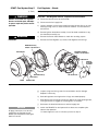
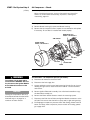
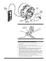
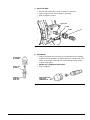
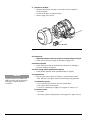
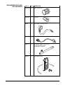
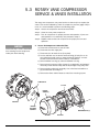
1
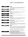
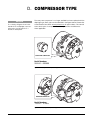
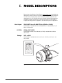
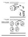
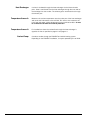
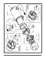
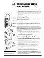
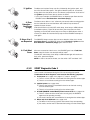
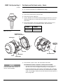
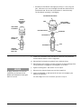
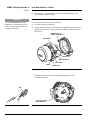
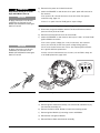
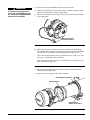
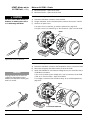
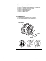
G-I PCM SERVICE MANUAL
M50/M80
SERIAL NUMBERS
VANE COMPRESSOR: 500000 - 699999
DIAPHRAGM COMPRESSOR: 700000 - 704999
Rev. H
CONTENTS
A.
SAFETY ...................................................................................... A-1
SAFETY CONSIDERATIONS ..............................................................A-2
B.
INTRODUCTION ......................................................................... B-1
C.
MODEL DESCRIPTIONS ............................................................ C-1
D.
COMPRESSOR TYPE ................................................................ D-1
1.0 TECHNICAL SPECIFICATIONS .................................................. 1-1
1.1 PHYSICAL .............................................................................. 1-2
1.2 ELECTRICAL........................................................................... 1-4
1.3 TORQUE SPECIFICATIONS ....................................................... 1-5
2.0 PRINCIPLES OF OPERATION ................................................... 2-1
2.1 COMPONENT DESCRIPTION .................................................... 2-1
2.2 MODES OF OPERATION .......................................................... 2-4
2.2.1 Standard Mode............................................................2-4
2.2.2 Preheat Mode............................................................. 2-5
2.2.3 Supplemental Mode.................................................... 2-6
3.0 MAINTENANCE TOOLS ............................................................. 3-1
4.0 TROUBLESHOOTING AND REPAIR ........................................... 4-1
4.1 SYSTEM AND COMPONENT DIAGNOSTICS................................ 4-2
4.1.1 EXAMPLE PROHEAT BEHAVIOR ERROR – Code 1 ........... 4-2
4.1.2 START Diagnostic Code............................................... 4-3
4.1.3 FLAME OUT Diagnostic Code ..................................... 4-26
4.1.4 COOLANT FLOW Diagnostic Code ............................... 4-27
4.1.5 OVERHEAT Diagnostic Code....................................... 4-29
4.1.6 VOLTAGE Diagnostic Code......................................... 4-29
4.1.7 FLAME FAULT Diagnostic Code .................................. 4-31
4.1.8 TEMPERATURE SENSOR T1 Diagnostic Code .............. 4-31
4.1.9 FUEL SHUT-OFF VALVE Diagnostic Code...................... 4-34
4.1.10 TEMPERATURE SENSOR T2 Diagnostic Code .............. 4-35
4.1.11 IGNITION MODULE Diagnostic Code ........................... 4-35
4.1.12 COOLANT PUMP Diagnostic Code............................... 4-36
4.1.13 MOTOR Diagnostic Code ........................................... 4-37
4.1.14 AUXILIARY OUTPUT Diagnostic Code .......................... 4-38
4.1.15 SWITCH/TIMER POWER Diagnostic Code .................... 4-38
4.2 COMPONENT MECHANICAL OR ELECTRICAL PROBLEMS.......... 4-39
4.2.1 Fuel Nozzle .............................................................. 4-39
4.2.2 Fuel Shut-off Valve .................................................... 4-39
4.2.3 Fuel Regulator .......................................................... 4-39
4.2.4 Air Compressor......................................................... 4-39
4.2.5 Fuel Supply Pump ..................................................... 4-39
4.2.6 Ignition Electrodes .................................................... 4-39
4.2.7 G-I PCM Fuse ........................................................... 4-39
4.3 OPERATIONAL PROBLEMS..................................................... 4-42
PROHEAT G-I PCM SERVICE MANUAL
i
5.0 MAINTENANCE .......................................................................... 5-1
5.1 WEEKLY MAINTENANCE .......................................................... 5-1
5.2 ANNUAL MAINTENANCE .......................................................... 5-2
5.3 ROTARY VANE COMPRESSOR SERVICE & VANES INSTALLATION .... 5-6
6.0 PROHEAT WARRANTY .............................................................. 6-1
ii
PROHEAT G-I PCM SERVICE MANUAL
A. SAFETY
Throughout this manual, you will see notes labeled DANGER, WARNING,
CAUTION, and NOTICE to alert you to special instructions or precautions
concerning a particular procedure that would be hazardous if performed
incorrectly or carelessly.
Observe them carefully!
These safety alerts alone cannot eliminate all hazards. Strict compliance
with these special instructions and common sense are major accident
prevention measures.
DANGER
Immediate hazards that will result
in severe injury or death.
WARNING
Hazards or unsafe practices that
could result in severe personal
injury or death.
CAUTION
Hazards or unsafe practices that
could result in minor injury or
product or property damage.
NOTICE
Information that is important to
proper installation or maintenance,
but is not hazard-related.
PROHEAT G-I PCM SERVICE MANUAL
A-1
SAFETY CONSIDERATIONS
WARNING
Exhaust
Inhalation of exhaust gas (containing carbon monoxide) may cause severe personal
injury and/or death. Anyone suspected of suffering from CO inhalation should be
removed from the hazardous area and given medical assistance immediately.
WARNING
Explosion Hazard
Do not operate heater where combustible fumes or airborne particles, such as sawdust, are present.
WARNING
Fuel
Exercise extreme caution when working near fuel or fuel-filled equipment. Do not
operate heater during fueling operations. In addition, do not smoke or handle open
flame equipment, such as a blowtorch, around fuel.
WARNING
Fire Hazard
Do not place any flammable items around the heater and exhaust pipe.
WARNING
Batteries
Wear hand and eye protection when working near batteries. Do not smoke or use open
flames near batteries.
WARNING
Electrical
Electric shock can cause severe personal injury, burns, and death. Before working on
any unit, disconnect the batteries. Use only approved materials and methods when
working on the electrical system and follow local electrical codes. Never work with
electricity in wet conditions or when you are feeling fatigued.
WARNING
Poisons/Toxins
Fuel and coolant are toxic and in some cases, carcinogenic. Wear eye and hand
protection at all times. Remove contaminated clothing immediately and wash
contaminated skin. Do not breathe in vapors.
WARNING
Moving/Hot Parts
Moving parts can cause severe injury and or death. Before working on any unit, shut it
off. Do not operate any unit until protective covers have been replaced. Always ensure
bolts and clamps are correctly torqued and secured. Inspect mechanical components
periodically for damage and corrosion.
WARNING
Coolant
Never remove the filler cap when the engine is hot – escaping steam or scalding water
could cause serious personal injury. The coolant level in the expansion tank should be
checked at least weekly (more frequently in high mileage or arduous conditions). Always
check the level when the system is cold. Unscrew the filler cap slowly, allowing the
pressure to escape before removing completely. Never run the engine without coolant.
Prevent anti-freeze coming in contact with the skin or eyes. If this occurs, rinse
immediately with plenty of water. Anti-freeze will damage painted surfaces.
Never top-up with salt water. Even when travelling in territories where the water supply
contains salt, always ensure you carry a supply of fresh (rain or distilled) water.
DANGER
California Proposition 65 Warning
Do not operate heater in garages or in other closed or unventilated areas.
Diesel exhaust and some of its constituents are known to the State of California to
cause cancer, birth defects, and other reproductive harm.
Electrical components in this product may contain lead, a chemical known to the
State of California to cause cancer and birth defects and other reproductive harm.
A-2
PROHEAT G-I PCM SERVICE MANUAL
B. INTRODUCTION
MODEL: M50/M80 G-I PCM
Figure B-1.
This manual is provided to assist in troubleshooting and maintaining the
PROHEAT M-Series heater. They are designed for use on any diesel-equipped
vehicle including trucks, buses (school, transit and coach), construction
equipment, off road equipment, military equipment and cargo.
PROHEAT heaters are used for the following applications:
(1) Engine Block Heat – The PROHEAT will preheat an engine block to ensure
reliable starting in cold weather. Its’ use throughout the year will reduce
engine wear caused by cold starts.
(2) Supplemental Heat (engine running) – The PROHEAT can be used while
the vehicle is operating to provide supplemental heat for the engine
and/or passenger compartment.
(3) Cargo Heat – The PROHEAT can supply heat to individual compartments
as a stand-alone heating system, or it can provide supplemental heat to
an existing heating system.
(4) Marine – Marine applications typically involve the engineering and
installation of a complete hot-water heating system of which PROHEAT
is only one component. SeaStar Solutions recommends that only an
expert in marine hot-water heating systems install a PROHEAT for
marine applications. NOTE: It is the installer’s responsibility to ensure
that an installation complies with all applicable codes and regulations.
PROHEAT G-I PCM SERVICE MANUAL
B-1
B-2
PROHEAT G-I PCM SERVICE MANUAL
C. PROHEAT CONTROL
MODULE (PCM) TYPE
The G-I Proheat Control Module (G-I PCM) is no longer available has been replaced
with the G-II PCM. The new G-II PCM incorporates a new dual mode analog/digital
temperature sensor and advanced Data Link software. Both styles can be
identified in the figures below. Please refer to the M-Series Parts Book at
www.proheat.com for part numbers.
THIS MANUAL COVERS ONLY THE G-I PCM.
Please see SL9157 for Service information on the G-II PCM.
METRI-PACK
12052641 AUX
CONNECTOR
KEYING
METRI-PACK
12052644 AUX
CONNECTOR
KEYING
2 X TWO PIN
ANALOG
TEMPERATURE
SENSOR
CONNECTORS
FOUR PIN
DUAL MODE
TEMPERATURE
SENSOR
CONNECTOR
STATUS
INDICATOR
LIGHT
6 PIN
DATA LINK
CONNECTOR
7 PIN
DATA LINK
CONNECTOR
G-II PCM
AIR FILTER
RETENTION
TANGS
NO AIR FILTER
RETENTION
TANGS
G-I PCM
Figure C-1. G-I PCM and G-II PCM.
PROHEAT G-I PCM SERVICE MANUAL
C-1
C-2
PROHEAT G-I PCM SERVICE MANUAL
D. COMPRESSOR TYPE
NOTICE
For continuity, all figures shown in this
manual will use a diaphragm compressor
unless where special instructions or
illustrations are required.
The rotary vane compressor is no longer available has been replaced with the
diaphragm type. Both styles can be identified in the Figures below. Please refer
to the M-Series Parts Book at www.proheat.com for part numbers. This manual
covers both styles of compressors and clearly identifies the differences
where applicable.
ROTARY VANE COMPRESSOR
Serial Numbers:
500000 – 699999
Figure D-1. Rotary Vane Compressor Type.
DIAPHRAGM COMPRESSOR
Serial Numbers:
700000 – To Date
Figure D-2. Diaphragm Compressor Type.
PROHEAT G-I PCM SERVICE MANUAL
D-1
D-2
PROHEAT G-I PCM SERVICE MANUAL
E. MODEL DESCRIPTIONS
Please refer to the M-Series Parts Book at www.proheat.com for detailed part
descriptions and part numbers. Included in the parts book are optional features
such as a timer, coolant pump and associated installation equipment and
maintenance tools. The following information describes the general characteristics
of M-Series models covered in this manual: Heat Output, G-I PCM CANbus,
Voltage, Fuel Fitting optional configurations, and Air Intake optional configurations.
Heat Output:
50,000 BTU/hr or 80,000 BTU/hr (15 kW or 23 kW).
The M-Series is available in either a 50,000 BTU/hr or 80,000 BTU/hr (15
kW or 23 kW) model.
G-I PCM:
CANbus SAE J1939.
The M-Series Proheat Control Module (G-I PCM) is available with CANbus
SAE J1939.
Voltage:
12 V or 24 V.
The M-Series is available in either a 12 V (10 – 15 VDC) or 24 V (20 – 30
VDC) model.
MODEL: M80-24V
XXXXXX
S/N:
POWER: 95 WATTS
FUEL TYPE: DIESEL
MAX PRESS: 2 BAR
OPER. VOLT: 20-30 VDC
HEAT OUTPUT: 24.0 KW
INSTALLATION DATE:
07
08
09
10
11
12
Made bt Teleflex Canada
Richmond BC Canada
PID 200101
Figure E-1.
PROHEAT G-I PCM SERVICE MANUAL
E-1
Fuel Fitting – Optional
Configurations
-4 JIC, NPT 1/8” and -4 Hose Barb.
There are fuel fitting options including JIC, NPT, hose barb and tight access.
Refer to parts book at www.proheat.com.
Figure E-2.
Air Intake – Optional
Configurations
Splash Guard, Straight and Right Angle Snorkel Attachments.
The M-Series can be equipped with a splash guard, straight and right angle
intake snorkels. Refer to parts book at www.proheat.com
NOTICE
For continuity, all figures shown in this
manual will use a splash guard intake.
SPLASH GUARD
STRAIGHT 3" OD
STRAIGHT SNORKEL
2.25" (55 mm) OD
SNORKEL ELBOW
26° SNORKEL ELBOW
Figure E-3. Air Intake Options.
E-2
PROHEAT G-I PCM SERVICE MANUAL
1.0 TECHNICAL
SPECIFICATIONS
RATING BTU/hr (kW)
M50 12V
M50 24V
M80 12V
M80 24V
50,000 (15)
50,000 (15)
80,000 (23)
80,000 (23)
SYSTEM VOLTAGE
Nominal DC Voltage (Range)
12 (10 – 15)
24 (20 – 30)
12 (10 – 15)
24 (20 – 30)
CURRENT DRAW (MAX) Amps
9.5
5.2
8.5
5.2
FUEL CONSUMPTION US gal/hr (L/hr)
0.48 (1.8)
0.48 (1.8)
0.78 (2.95)
0.78 (2.95)
IGNITION TYPE
Electronic Spark Ignition
COOLANT OUTPUT TEMPERATURE MAX.
185°F (85°C)
AMBIENT OPERATING TEMPERATURE
-40°F to +122°F (-40°C to +50°C)
WEIGHT lbs (kg)
53 (24)
HEAT EXCHANGER CAPACITY US gal (l)
0.5 (2)
COOLANT SYSTEM
Minimum Capacity US gal (l)
Recommended Flow Rate Through
Heater US gpm (lpm)
2.64 (10)
2.64 (10)
2.64 (10)
2.64 (10)
5 (19)
5 (19)
7 (26.5)
7 (26.5)
DANGER
Do not use gasoline.
FUEL TYPES
COMPATIBLE
Diesel (ULSD, #1, #2, Arctic), JP8, Jet A1
Bio Fuels - Contact Proheat www.proheat.com
SYSTEM OUTPUTS
AUXILIARY OUTPUT
Same as System Voltage
Maximum 1 Amp draw (over-load shut-off protection)
High-side switched
SWITCH/TIMER
POWER
Same as System Voltage
Maximum 1 Amp draw (over-load shut-off protection)
High-side switched
COOLANT PUMP
Same as System Voltage
Maximum 10 Amp draw (over-load shut-off protection)
High-side switched
INDICATOR LIGHT
Same as System Voltage
Maximum 1 Amp draw (over-load shut-off protection)
High-side switched
SYSTEM INPUTS
PROHEAT G-I PCM SERVICE MANUAL
SWITCH
10 – 30V
Standard Run Mode
Preheat Run Mode
Supplemental Run Mode
COOLANT PUMP
AUXILIARY
10 – 30V
Allows independent operation of Coolant Pump through
the Proheat Control Module
POWER
12 Volt or 24 Volt
1-1
1.1 PHYSICAL
INLET SEE NOTE 8
T2 SECONDARY TEMPERATURE
SENSOR LOCATION (SENSOR
NOT SHOWN) SEE NOTE 8
9.55 (243)
1.97 (50)
OUTLET SEE NOTE 8
T1 PRIMARY TEMPERATURE
SENSOR SEE NOTE 8
2 x 1.50 (38)
TOP VIEW
SERVICE SPACE REQUIREMENT
(MAY VARY SEE NOTE 3 & PAGE 1-3)
10.13 (257)
23.24 (590)
5.77
(147)
-4 JIC MALE FUEL INLET (INTERNAL
FUEL FILTER) (SEE NOTE 5)
G-I PCM
9.00 (229)
8.58
(218)
4.45
(113)
FRONT VIEW
AIR INTAKE
ALTERNATE
SNORKELS
AVAILABLE
(SEE PAGE 1-3 )
5.39
(137)
2.03 (52)
EXHAUST
(SEE NOTE 2 AND 4)
3.98
(101)
8.14 (207)
7.63
(194)
HEAT EXCHANGER
(SEE NOTE 6)
.75 (19)
REAR VIEW
SIDE VIEW
3.23
12.60 (320)
(82)
2.75 (70)
4 x M8 x 1.25 MOUNTING PEM NUTS
4.33 5.90
(110) (150)
6 x .41 (10)
BOTTOM VIEW
NOTES:
1-2
1. DIMENSIONS ARE IN INCHES (MILLIMETERS IN BRACKETS).
2. TYPICAL EXHAUST CUTOUT 3.25" CENTERED ON EXHAUST.
3. SERVICE SPACE REQUIRED TO REMOVE BURNER HEAD AND
COMBUSTION TUBE FOR PERIODIC INSPECTION AND CLEANING.
4. THE EXHAUST PIPE SHOULD HAVE A MINIMUM DIAMETER OF
2.75", A MAXIMUM LENGTH OF 5' AND HAVE NO MORE THAN
180° OF BENDS.
5. ALTERNATE FUEL INLET CONFIGURATIONS AVAILABLE, SEE
PARTS BOOK FOR FURTHER INFORMATION.
6. ALTERNATE HEAT EXCHANGERS AVAILABLE, SEE PARTS BOOK
FOR FURTHER INFORMATION.
7. SNORKEL HOSE REQUIRED FOR THIS AIR INTAKE OPTION.
CONTACT TECH SUPPORT AT WWW.PROHEAT.COM FOR
LENGTH AND BEND RESTRICTIONS
8. THE INLET AND OUTLET CAN BE REVERSED WITH THE ADDITION
OF A T2 SECONDARY TEMPERATURE SENSOR.
PROHEAT G-I PCM SERVICE MANUAL
5.77
(147)
24.31 (617)
AIR INTAKE OPTION:
3" OD SNORKEL SEE NOTE 7
29.09 (637)
AIR INTAKE OPTION:
2.25" OD ELBOW WITH
27° ADAPTER PLATE SEE NOTE 7
24.00 (610)
AIR INTAKE OPTION:
2.25" OD SNORKEL SEE NOTE 7
24.80 (630)
AIR INTAKE OPTION: 2.25" OD ELBOW SEE NOTE 7
CAN BE INSTALLED AT 0°, 90°, 180°, 270°
SERVICE
SPACE
REQUIREMENT
(SEE NOTE 3)
9.21 (234)
5.77
(147)
SERVICE
SPACE
REQUIREMENT
(SEE NOTE 3)
9.99 (254)
5.77
(147)
SERVICE
SPACE
REQUIREMENT
(SEE NOTE 3)
8.90 (226)
5.77
(147)
SERVICE
SPACE
REQUIREMENT
(SEE NOTE 3)
90°
0°
180°
9.70 (246)
NOTES:
1. DIMENSIONS ARE IN INCHES (MILLIMETERS IN BRACKETS).
2. TYPICAL EXHAUST CUTOUT 3.25" CENTERED ON EXHAUST.
3. SERVICE SPACE REQUIRED TO REMOVE BURNER HEAD AND
COMBUSTION TUBE FOR PERIODIC INSPECTION AND CLEANING.
4. THE EXHAUST PIPE SHOULD HAVE A MINIMUM DIAMETER OF
2.75", A MAXIMUM LENGTH OF 5' AND HAVE NO MORE THAN
180° OF BENDS.
5. ALTERNATE FUEL INLET CONFIGURATIONS AVAILABLE, SEE
PARTS BOOK FOR FURTHER INFORMATION.
PROHEAT G-I PCM SERVICE MANUAL
270°
6. ALTERNATE HEAT EXCHANGERS AVAILABLE, SEE PARTS BOOK
FOR FURTHER INFORMATION.
7. SNORKEL HOSE REQUIRED FOR THIS AIR INTAKE OPTION.
CONTACT TECH SUPPORT AT WWW.PROHEAT.COM FOR
LENGTH AND BEND RESTRICTIONS
8. THE INLET AND OUTLET CAN BE REVERSED WITH THE ADDITION
OF A T2 SECONDARY TEMPERATURE SENSOR.
1-3
1-4
A
B
C
D
E
F
G
H
A
B
C
A
B
C
D
E
F
A
B
C
D
E
F
G
H
A
B
C
A
B
C
D
E
F
P2
CONTROL
P6
CAN BUS
A
B
A
B
P4
COOLANT PUMP
OUTPUT
PROHEAT G-I PCM
A
B
A
B
P5
AUXILIARY
OUTPUT
P3
DATALINK
A
B
A
B
P1
POWER
PROHEAT G-I PCM
CONNECTOR
PART#
ON
LOCATED AS PER CUSTOMER
REQUEST OR OEM REQUIREMENT
MECHANICS DISABLE
SWITCH MOUNTED IN A
PROTECTED LOCATION
INDICATOR
LIGHT
GREEN
RED
COOLANT PUMP GROUND
COOLANT PUMP OUTPUT
O.E.M. SUPPLIED
GROUND (AUXILIARY OUTPUT) (1 AMP MAX)
AUXILIARY OUTPUT (HIGH SIDE SWITCHED) (1 AMP MAX)
FACTORY USE (N/A)
RS232 Tx
ACCESSORY POWER OUTPUT (1 AMP MAX SHARED WITH P2-C)
INDICATOR OUTPUT (1 AMP MAX)
GROUND (1 AMP MAX)
RS232 Rx
SHIELD
CAN-L
CAN-H
PUMP (COOLANT) SWITCH INPUT (ACTIVE HIGH)
SUPPLEMENTAL SWITCH INPUT (ACTIVE HIGH)
PREHEAT SWITCH INPUT (ACTIVE HIGH)
MAIN SWITCH INPUT (STANDARD "ON" SIGNAL OR PREHEAT UNLATCH) (ACTIVE HIGH)
GROUND (ACCESSORY OUTPUT GROUND) (1 AMP MAX)
MAXIMUM
10 AMPS
POWER OUTPUT (CONSTANT POWER. TIMER/SWITCH REMOTE PANEL) (1 AMP MAX SHARED WITH P3-D)
P1-POWER
P2-CONTROL (SWITCH)
P3-DATALINK (DOWNLOAD)
P4-PUMP (COOLANT)
P5-AUXILIARY
P6-CAN BUS
G-I PCM CONNECTOR
15300027
12047937
12052848
12052641
12052641
12110293
15300014
12066304
12052850
12052634
12052634
12052845
LOCK
PART#
OFF
TIMER OPTION
12077413
12048074
12048074
12048074
12048074
12048074
12015193
12048086
12048086
12048086
12048086
12048086
---12059168
12059168
----------
TERMINAL WIRE SEAL CAVITY SEAL
PART#
PART#
PART#
SIGNAL FROM OEM HEATING SYSTEM TO
TURN ON COOLANT PUMP WHEN REQUIRED
FOR A REASON OTHER THAN WHEN THE
HEATER REQUIRES THE PUMP
ENGINE RUN (ALTERNATOR SIGNAL)
SPRING CENTRED
DOUBLE THROW
MOMENTARY SWITCH.
LOCATED ON THE
DRIVERS CONSOLE.
WHITE
VEHICLE
GROUND
(-)
3/ ALL UNUSED CONNECTIONS ON THE PCM ARE
SUPPLIED WITH SEAL PLUGS ON STANDARD
HEATERS.
2/ 280 SERIES CONNECTOR ASSEMBLIES TO BE
USED WITH 10AWG WIRE WITH MAXIMUM
.161" INSULATION DIAMETER. WIRE MUST
MEET OR EXCEED SAE J1128 GPT OR GXL.
1/ 150 SERIES CONNECTOR ASSEMBLIES TO BE
USED WITH 18AWG WIRE WITH MAXIMUM
.1" INSULATION DIAMETER. WIRE MUST MEET
OR EXCEED SAE J1128 GPT SPECIFICATIONS.
NOTES:
BLACK
(+)
POWER
SUPPLY
P4 - PUMP (COOLANT)
METRI-PACK 150 SERIES, 2 PIN
NOTE 1
NOTE 3
P6 - CANBUS (OPTIONAL)
METRI-PACK 150 SERIES, 3 PIN
NOTE 1
NOTE 3
P7 - T2: TEMP SENSOR
NOTE 3
P8 - T1: TEMP SENSOR
GROUND (INDICATOR GROUND) (1 AMP MAX)
30 AMP
FUSE
PROHEAT G-I PCM
INDICATOR OUTPUT (HIGH SIDE SWITCHED. DASH OR PROHEAT TOGGLE SWITCH LIGHT) (1 AMP MAX)
BATTERY NEGATIVE (GROUND)
BATTERY POSITIVE (FUSE/BREAKER 30 AMP)
O.E.M. SUPPLIED
P1 - POWER
METRI-PACK 280 SERIES, 2 PIN
NOTE 2
P2 - CONTROL (SWITCH)
METRI-PACK 150 SERIES, 8 PIN
NOTE 1
P3 - DATALINK (DOWNLOAD)
METRI-PACK 150 SERIES, 6 PIN
NOTE 1
NOTE 3
P5 - AUX (OUTPUT)
METRI-PACK 150 SERIES, 2 PIN
NOTE 1
NOTE 3
1.2 ELECTRICAL
PROHEAT G-I PCM SERVICE MANUAL
1.3 TORQUE SPECIFICATIONS
Solenoid Valve
•
•
•
•
Lubricate O-ring with diesel fuel.
Install solenoid valve by hand.
Ensure poppet and spring remain in place during assembly.
Torque solenoid valve to fuel block to 25 in. lbs. ± 3 in. lbs.
(2.8 Nm ± 0.3 Nm).
Regulator
• Install 2 o-rings on back side of regulator (not shown).
• Torque screws (2) to 75 in. lbs. ± 3 in. lbs. (8.5 Nm ± 0.3 Nm).
Fuel Delivery Block
• Ensure all three O-rings are in place.
• Torque screws (3) to 75 in. lbs. ± 7 in. lbs. (8.5 Nm ± 0.8 Nm).
Nozzle
• Lubricate O-ring on nozzle with diesel fuel.
• Torque nozzle to fuel block to 150 in. lbs. ± 10 in. lbs.
(16.9 Nm ± 1.1 Nm).
Nozzle Assembly
• Torque nozzle to nozzle stem to 30 in. lbs. ± 3 in. lbs. (3.4Nm ± .3 Nm).
PROHEAT G-I PCM SERVICE MANUAL
1-5
Motor
• Rotate motor shaft until motor drops into fuel pump gear..
• Ensure correct alignment (refer to ‘Motor Replacement’ on page 4-25)
• Torque bolts (4) to 75 in. lbs. ± 7 in. lbs. (8.5 Nm ± 0.8 Nm).
Blower Housing
• Torque bolts (2) to 75 in. lbs. ± 7 in. lbs. (8.5 Nm ± 0.8 Nm).
Ignition Module
• Torque screws (2) to 75 in. lbs. ± 7 in. lbs. (8.5 Nm ± 0.8 Nm).
Temperature Sensor
• Install O-ring onto sensor.
• Torque sensor to 100 in. lbs. ± 10 in. lbs. (11.6 Nm ± 1.1 Nm).
Burner Head/Heat Exchanger
• Torque bolts (2) to 100 in. lbs. ± 10 in. lbs. (11.6 Nm ± 1.1 Nm).
1-6
PROHEAT G-I PCM SERVICE MANUAL
Enclosure Lid (Optional)
• Torque screws (4) to 100 in. lbs. ± 10 in. lbs. (11.6 Nm ± 1.1 Nm).
Fuel Filter Fitting
• Install O-ring onto fitting.
• Torque fitting to 100 ± 10 in. lbs. (11.3 ± 1.1 Nm).
Rotary Vane Compressor ONLY
Serial Numbers 500000 – 699999
• Install O-rings into burner flange.
• Install compressor into burner flange. (Ensure correct alignment—refer to
‘Compressor Replacement’ on page 4-15)
• Torque screws (2) to 75 in. lbs. ± 3 in. lbs. (8.5 Nm ± 0.3 Nm).
Diaphragm Compressor ONLY
Serial Numbers 70000 and above
• Install O-rings in to cylinder head and valve cover (not shown).
• Ensure connecting rod is at BDC and ensure the diaphragm is concentric
to the diaphragm opening (not shown).
• Torque to 27 in. lbs +/- 3 in. lbs using a crisscross pattern.
Relief Valve – for Use with Rotary Vane Compressor ONLY
Serial Numbers 600000 – 699999
• Torque to 25 in. lbs. ± 3 in. lbs. (2.8 Nm ± 0.3 Nm).
PROHEAT G-I PCM SERVICE MANUAL
1-7
1-8
PROHEAT G-I PCM SERVICE MANUAL
2.0 PRINCIPLE OF
OPERATION
2.1 COMPONENT DESCRIPTIONS
Combustion Air Blower:
Motor:
Fuel Supply Pump:
Fuel Regulator:
Fuel Nozzle:
Impeller-style blower driven by the Motor provides the principle combustion air.
Drives the Combustion Air Blower, Air Compressor and Fuel Supply Pump.
A positive displacement, gear-type pump that draws fuel from the vehicle fuel
tank and supplies it to the Fuel Regulator. Pressure is regulated between
7 – 10 PSI by means of an internal relief valve. Fuel is re-circulated within the
pump, therefore a fuel return line to the tank is not required.
Diaphragm-type pressure reducing valve. The Fuel Regulator drops the fuel
supply pressure to atmospheric pressure (0 PSI).
Air-aspirating type burner nozzle. Compressed air flows through the air
passages, exiting the nozzle in front of the fuel orifice creating a vacuum in
the fuel supply. This draws fuel from the Fuel Regulator and the combined
fuel/air mixture is atomized into the combustion chamber.
Fuel Shut-off Valve:
Electrically operated solenoid valve which controls fuel flow to the Fuel Nozzle.
Air Compressor:
Diaphragm compressor that supplies air pressure to the Fuel Nozzle. Note that
older versions of M-Series use a rotary vane compressor. Refer to page D-1 for
more information.
Air Relief:
Regulates air pressure to the fuel nozzle.
For use with Rotary Vane Compressor ONLY Serial Numbers 600000 – 699999.
Ignition Module:
G-I PCM:
(PROHEAT Control Module)
Combustion Tube:
PROHEAT G-I PCM SERVICE MANUAL
Electronic Ignition Module with plug-in electrode.
Electronic control module monitors the PROHEAT sensors, operating conditions,
and controls the Motor and other devices. Diagnostics are utilized for both
safety in operations and detection of component faults to aid in service and
troubleshooting. The G-I PCM contains the flame sensor which senses the flame
intensity. This information can be retrieved by a personal computer using
PROHEAT Datalink software.
Directs the air supplied by the blower through a swirler into the combustion
zone, mixing it with the atomized fuel/air mixture from the Fuel Nozzle.
2-1
Heat Exchanger:
Temperature Sensor 1:
Measures the coolant temperature near the outlet port of the heat exchanger
and sends this information to the G-I PCM. This sensor also measures the
inner heat exchanger surface temperature for an overheat condition. It must
be connected at all times for overheat protection.
Temperature Sensor 2:
For installations where the coolant flow through the heat exchanger is
opposite of what is specified on page 1-2 and page 2-3.
Coolant Pump:
2-2
Coolant is circulated through the heat exchanger via the inlet and outlet
ports. Heat is transferred from the heat exchanger through the inner wall of
the exchanger into the coolant. The exhaust gases are directed out through
the exhaust port.
Circulates coolant through the PROHEAT and vehicle heating system.
Depending on the PROHEAT installation, it may be operated by the G-I PCM.
PROHEAT G-I PCM SERVICE MANUAL
PROHEAT G-I PCM SERVICE MANUAL
2-3
BLOWER HOUSING
BURNER HEAD
FLANGE WITH BUILT
IN AIR COMPRESSOR
FUEL
SHUT-OFF
VALVE
AIR FILTER
IGNITION
ELECTRODES
G-I PCM (PROHEAT CONTROL MODULE)
COMBUSTION AIR BLOWER
FUEL
SUPPLY
PUMP
FUEL
NOZZLE
IGNITION MODULE
FUEL REGULATOR
MOTOR
COMBUSTION
TUBE
BURNER HEAD
FLANGE WITH
BUILT IN AIR
COMPRESSOR
REQUIRED
FOR REVERSE
COOLANT FLOW
TEMPERATURE
SENSOR 2
(IF EQUIPPED)
AIR COMPRESSOR
INLET
TEMPERATURE
SENSOR 1
OUTLET
AIR RELIEF
ROTARY VANE COMPRESSOR
SERIAL NUMBERS
600000 – 699999
HEAT EXCHANGER
2.2 MODES OF OPERATION
The Proheat Control Module (G-I PCM) has three modes of operation: Standard,
Preheat and Supplemental. Depending on the installation, more than one mode
may be wired for operation. The wired modes may be identified by referring to
the installation wiring diagram to determine the G-I PCM pins on P2 Control that
have been connected. This wiring diagram may be compared with the drawing
in Section 1.2 Electrical. The following is a summary of the operation modes:
Standard Heat Mode
• normal operation of the
Proheat
• over-rides and drops out
preheat mode
• overrides supplemental
mode
2.2.1
1. Switch “ON”
Standard
Mode Signal
2-4
Preheat Mode
• similar to standard
mode Except: 90 minute
time out.
• activated via momentary
contact push button
switch with latching
internal to the G-I PCM
Supplemental Heat Mode
• similar to standard mode
except: coolant pump
does not run when
Proheat is not firing
• overrides and drops out
preheat mode
• 30 second signal
required before mode
enabled
• No delay required for
mode switch off
STANDARD MODE
The ON/OFF switch lamp, timer lamp or OEM indicator (installation options)
will light. If the coolant temperature is below 160°F (71°C) the PROHEAT
enters Pre-check. If the coolant temperature is above 160°F (71°C) the
PROHEAT enters Standby.
2. Precheck
The G-I PCM performs self diagnosis checking sensors for correct range,
electrical components for over-load and for a flame presence. Also during the
first Pre-check, the Ignition Module sparks for five seconds to allow a service
technician to visually check for a spark. If there are no errors indicated, the
PROHEAT goes to Ignition.
3. Ignition
The Motor and Coolant Pump start first, followed by the ignition spark, and
then Fuel Shut-off Valve opens. The Ignition Module sparks for 30 seconds
during which time the flame sensor must detect a correct flame. At the end
of the Ignition cycle the Flame Sensor checks the flame:
• If the PROHEAT detects proper flame, it enters Full Output.
• If the PROHEAT does not detect proper flame, the PROHEAT enters Cool Down
(Purge). The PROHEAT will attempt to start again moving into Pre-check after
Cool Down (Purge). If the second start cycle fails, the PROHEAT will enter
Fault Shut Down.
4. Full Output
The PROHEAT will continue in Full Output until the coolant temperature reaches
185°F (85°C) at the PROHEAT outlet Temperature Sensor. The PROHEAT closes
the Fuel Shut-off Valve and goes into Cool Down (Purge).
5. Cool Down (Purge)
The Motor and Coolant Pump continue to operate for three minutes. After three
minutes, the Motor stops and the PROHEAT enters Standby. The PROHEAT
will Cool Down (Purge) for three reasons:
• Coolant reaches 185°F (85°C).
• A fault is detected. Go to Section 4.0 Troubleshooting and Repair, page 4-1.
• The PROHEAT is operating in Ignition or Full Output when it is switched off.
PROHEAT G-I PCM SERVICE MANUAL
CAUTION
Always ensure that the PROHEAT is allowed to Cool Down (Purge) for a full 3
minutes. If the power is shut off without a proper Cool Down (Purge) during
Full Output, DAMAGE TO THE HEATER MAY OCCUR.
6. Standby
7. Switch “OFF”
8. Fault Shut
Down
The Coolant Pump continues to circulate coolant throughout the system.
When the coolant temperature drops below 160°F (71°C), the G-I PCM will
enter the cycle starting at Pre-check. The PROHEAT will continue to repeat
Steps 2 to 6 until it is switched “OFF.”
The ON/OFF switch lamp, timer lamp or OEM indicator (installation options)
will turn off.
If the PROHEAT is in Full Output, it will Purge first and then shut “OFF”.
If the PROHEAT is in Standby, it will shut “OFF” immediately.
If the PROHEAT diagnostics sense a system or component fault, the
PROHEAT will shut down all components and flash a fault code(s) which best
represents the conditions. To reset the PROHEAT, it must be switched off
and then on again.
NOTE: Damage may occur it the fault codes are ignored and the PROHEAT is
repeatedly switched off and on without addressing the problem.
2.2.2
1. Momentary Switch
“ON” Preheat
Mode Signal
PREHEAT MODE (ENGINE OFF)
The ON/OFF switch lamp, timer lamp or OEM indicator (installation options)
will light. If the coolant temperature is below 160°F (71°C) the PROHEAT
enters Pre-check. If the coolant temperature is above 160°F (71°C) the
PROHEAT enters Standby.
2. Precheck
The G-I PCM performs self diagnosis checking sensors for correct range,
electrical components for over-load and for a flame presence. Also during the
first Pre-check, the Ignition Module sparks for five seconds to allow a service
technician to visually check for a spark. If there are no errors indicated, the
PROHEAT goes to Ignition.
3. Ignition
The Motor and Coolant Pump start first, followed by the ignition spark, and
then Fuel Shut-off Valve opens. The Ignition Module sparks for 30 seconds
during which time the flame sensor must detect a correct flame. At the end
of the Ignition cycle the Flame Sensor checks the flame:
• If the PROHEAT detects proper flame, it enters Full Output.
• If the PROHEAT does not detect proper flame, the PROHEAT enters Cool Down
(Purge). The PROHEAT will attempt to start again moving into Pre-check
after Cool Down (Purge). If the second start cycle fails, the PROHEAT will
enter Fault Shut Down.
4. Full Output
The PROHEAT will continue in Full Output until the coolant temperature reaches
185°F (85°C) at the PROHEAT outlet Temperature Sensor. The PROHEAT closes
the Fuel Shut-off Valve and goes into Cool Down (Purge).
5. Cool Down (Purge)
The Motor and Coolant Pump continue to operate for three minutes. After three
minutes, the Motor stops and the PROHEAT enters Standby. The PROHEAT
will Cool Down (Purge) for three reasons:
• Coolant reaches 185°F (85°C).
• A fault is detected. Go to Section 4.0 Troubleshooting and Repair, page 4-1.
• The PROHEAT is operating in Ignition or Full Output when it is switched off.
PROHEAT G-I PCM SERVICE MANUAL
2-5
CAUTION
Always ensure that the PROHEAT is allowed to Cool Down (Purge) for a full 3
minutes. If the power is shut off without a proper Cool Down (Purge) during
Full Output, DAMAGE TO THE HEATER MAY OCCUR.
6. Standby
7. After 90 mins. or
a Momentary
Switch “OFF"
Signal
8. Fault Shut
Down
The Coolant Pump continues to circulate coolant throughout the system.
When the coolant temperature drops below 160°F (71°C), the G-I PCM will
enter the cycle starting at Pre-check. The PROHEAT will continue to repeat
Steps 2 to 6 until it is switched “OFF.”
The ON/OFF switch lamp, timer lamp or OEM indicator (installation options)
will turn off.
If the PROHEAT is in Full Output, it will Purge first and then shut “OFF”.
If the PROHEAT is in Standby, it will shut “OFF” immediately.
If the PROHEAT diagnostics sense a system or component fault, the
PROHEAT will shut down all components and flash a fault code(s) which best
represents the conditions. To reset the PROHEAT, it must be switched off
and then on again.
NOTE: Damage may occur it the fault codes are ignored and the PROHEAT is
repeatedly switched off and on without addressing the problem.
2.2.3
1. Supplemental Mode
Signal "ON"
(Engine Running)
The ON/OFF switch lamp, timer lamp or OEM indicator (installation options)
will light after 30 seconds of contentiously receiving the signal. If the coolant
temperature is below 160°F (71°C) the PROHEAT enters Pre-run. If the coolant
temperature is above 160°F (71°C) the PROHEAT enters Supplemental
Standby (coolant pump off). If the coolant pump is requested on via the
coolant pump input (analog or CAN) the PROHEAT enters Standby (coolant
pump on) and will move directly to Pre-check.
2. Pre-Run
The coolant pump operates for 30 seconds to circulate coolant through the
system. If the coolant temperature is above 160°F (71°C) at the end of 30
seconds, the pump shuts off and the PROHEAT returns to Supplemental
Standby (coolant pump off). If the coolant temperature remains below 160°F
(71°C) after 30 seconds, the PROHEAT goes to Pre-check (with the coolant
pump on).
3. Pre-check
4. Ignition
2-6
SUPPLEMENTAL MODE (ENGINE RUNNING)
The G-I PCM performs self diagnosis checking sensors for correct range,
electrical components for over-load and for a flame presence. Also during the
first Pre-check, the Ignition Module sparks for five seconds to allow a service
technician to visually check for a spark. If there are no errors indicated, the
PROHEAT goes to Ignition.
The Motor starts first, followed by the ignition spark, and then Fuel Shut-off
Valve opens. The Ignition Module sparks for 30 seconds during which time
the flame sensor must detect a correct flame. At the end of the Ignition cycle
the Flame Sensor checks the flame:
• If the PROHEAT detects proper flame, it enters Full Output.
• If the PROHEAT does not detect proper flame, the PROHEAT enters Cool
Down (Purge). The PROHEAT will attempt to start again moving into Precheck after Cool Down (Purge). If the second start cycle fails, the
PROHEAT will enter Fault Shut Down.
PROHEAT G-I PCM SERVICE MANUAL
5. Full Output
The PROHEAT will continue in Full Output until the coolant temperature reaches
185°F (85°C) at the PROHEAT outlet Temperature Sensor. The PROHEAT closes
the Fuel Shut-off Valve and goes into Cool Down (Purge).
6. Cool Down (Purge)
The Motor and Coolant Pump continue to operate for three minutes. After three
minutes, the Motor and Coolant Pump stop and the PROHEAT enters
Supplemental Standby (coolant pump off). The PROHEAT will Cool Down
(Purge) for three reasons:
• Coolant reaches 185°F (85°C).
• A fault is detected. Go to Section 4.0 Troubleshooting and Repair, page 4-1.
• The PROHEAT is operating in Ignition or Full Output when it is switched off.
CAUTION
Always ensure that the PROHEAT is allowed to Cool Down (Purge) for a full 3
minutes. If the power is shut off without a proper Cool Down (Purge) during
Full Output, DAMAGE TO THE HEATER MAY OCCUR.
7. Supplemental
Standby
(Coolant pump off)
The Coolant Pump is “OFF” but the G-I PCM continuously monitors the coolant
temperature. If the coolant temperature drops below 160°F (71°C), the G-I PCM
will enter the cycle starting at Pre-run. The PROHEAT will continue to repeat
Steps 2 to 6 until it is switched “OFF.”
7A. Standby
(Coolant pump on)
If the coolant pump is requested on via the coolant pump input (analog or
CAN) the PROHEAT enters Standby (coolant pump on). If the coolant
temperature drops below 160°F (71°C) the PROHEAT will move directly to
Pre-check (step 3).
If the coolant pump is no longer requested on via the coolant pump input (analog
or CAN) the PROHEAT enters Supplemental Standby (coolant pump off).
8. Supplemental
Mode Signal
Removed
(Engine off)
The ON/OFF switch lamp, timer lamp or OEM indicator (installation options)
will turn off.
If the PROHEAT is in Full Output, it will Purge first and then shut “OFF”.
If the PROHEAT is in Standby, it will shut “OFF” immediately.
NOTICE
There is no time delay to shut off the PROHEAT in Supplemental Mode.
9. Fault Shut
Down
If the PROHEAT diagnostics sense a system or component fault, the
PROHEAT will shut down all components and flash a fault code(s) which best
represents the conditions. To reset the PROHEAT, it must be switched off
and then on again.
NOTE: Damage may occur it the fault codes are ignored and the PROHEAT is
repeatedly switched off and on without addressing the problem.
PROHEAT G-I PCM SERVICE MANUAL
2-7
2-8
PROHEAT G-I PCM SERVICE MANUAL
3.0 MAINTENANCE TOOLS
The following list is the minimum recommended tools to properly service the
M-Series. Please refer to the M-Series parts book at www.proheat.com for
additional PROHEAT service tools and computer software.
Minimum Proheat Service Tools
1. Remote Start Switch (P/N PK0091)
2. Temperature Sensor (P/N 200302K for G-I PCM)
3. Test Gauge, Air Pressure Digital Manometer (P/N PK0036)
4. Test Gauge, Air/Fuel Pressure (P/N PK0067)
5. Test Gauge Adaptor (P/N PK0091)
Rotary Vane Compressor Models ONLY (SN 600000 to 699999)
NOTICE
Additional standard hand tools may
be required. This list is not intended
to be exhaustive.
PROHEAT G-I PCM SERVICE MANUAL
Minimum Standard Hand Tools
•
•
•
•
•
•
•
•
•
•
•
•
•
•
•
•
Digital Multimeter
Ratchet – 3/8" drive
Extension, 12" – 3/8" drive
Socket, 13 mm – 3/8" drive
Screw Driver, Flat Blade 1/4" blade
Allen Key, 4 mm – 3/8" drive or extension T-handle
Allen Key, 5 mm – 3/8" drive or extension T-handle
Allen Key, 9/64"
2x Combination Wrench, 3/4"
Combination Wrench, 5/8"
Combination Wrench, 9/16”
Combination Wrench, 7/16”
Wire Brush
Adjustable Wrench
Vise Grip
Torque Wrench 25 – 150 in. lbs. [2.8 – 17 Nm]
3-1
3-2
PROHEAT G-I PCM SERVICE MANUAL
4.0 TROUBLESHOOTING
AND REPAIR
Problems with the PROHEAT and its operation will be indicated in two ways:
1. PROHEAT Diagnostic Faults indicated by means of a flashing diagnostic code
on a OEM indicator light (if equipped). Go to page 4-2.
2. Operational problems may not be identified with a flashing diagnostic code
(e.g., blown fuse, obstructed coolant flow, air leaks in fuel supply line).
Go to page 4-42.
Troubleshooting a Problem
STEP 1
Locate the PROHEAT, remove the enclosure lid if used and visually check for
any problems with wiring harnesses, fuel leaks, coolant leaks, exhaust pipe
damage and environmental condition.
STEP 2
Check the diagnostic indicator light, and if it's flashing, determine the code
based on page 4-2.
STEP 3
If no code is indicated, turn the PROHEAT off and then on again using the
existing operational switches, timer or a PROHEAT remote start switch
(PROHEAT P/N PK0091).
STEP 4
Let the PROHEAT attempt to start and/or operate. Observe the operation.
NOTE: The PROHEAT will always attempt to start twice, as long as the coolant
temperature is below 160°F (71°C). If a fault is detected it will shut down, go
through a Cool Down (Purge) and attempt a second start. After both attempts
to start or operate, an indicator light will flash a diagnostic code.
Go to page 4-2.
• If the indicator light flashes, count the number of flashes and refer to
the troubleshooting diagnostic code description for that number on the
following pages.
• If the PROHEAT runs but is not performing or operating correctly, consult
the Operational Problems section,page 4-42.
Troubleshooting and Repair Tools Required
• Test Gauge, Air Pressure Digital Manometer (PROHEAT P/N PK0036)
Allows the service technician to check the air compressor pressure to
ensure correct fuel delivery.
• Remote Start Switch (PROHEAT P/N PK0091)
Allows the service technician to work at the PROHEAT. Isolates the
PROHEAT from the existing vehicle system controls and comes with a
built-in indicator light.
• Temperature Sensor (PROHEAT P/N P/N 200302K G-I PCM)
Allows the service technician to start a PROHEAT when the coolant
temperature is greater than 160°F (71°C). To be used only for
troubleshooting.
• Test Gauge, Air/Fuel Pressure (PROHEAT P/N PK0067)
Allows the service technician to check the fuel pressure to ensure correct
fuel delivery (can also be used for air pressure measurements).
Figure 4-1: Air Pressure — Digital
Manometer, Remote Start Switch,
Temperature Sensor, Fuel Pressure
Test Gauge and Test Gauge Adaptor.
PROHEAT G-I PCM SERVICE MANUAL
• Test Gauge Adaptor (PROHEAT P/N PK0091)
Rotary Vane Compressor Models ONLY (SN 600000 to 699999)
Allows the service technician to measure the air compressor pressure and
adjust the air relief at the same time.
4-1
4.1 SYSTEM AND COMPONENT
DIAGNOSTICS
The G-I PCM continually monitors the PROHEAT operating conditions. If the G-I
PCM detects a problem, the indicator light flashes a diagnostic code(s).
The diagnostic indicator light may be located:
• In the toggle of the ON/OFF Switch provided by PROHEAT (standard
installation kit).
• In the PROHEAT Timer manual ON light (red).
• In an OEM indicator light package.
• In the remote switch (PROHEAT P/N PK0091) used for troubleshooting.
NO. OF
FLASHES
SYSTEM
DIAGNOSTICS
COMPONENT
DIAGNOSTICS
4.1.1
1
2
3
4
5
6
7
8
9
10
11
12
13
14
DIAGNOSTIC CODE
DESCRIPTION
Start
Flame Out
Coolant Flow
Overheat
Voltage
Flame Fault
Temperature Sensor T1
Fuel Shut-off Valve
Temperature Sensor T2
Ignition Module
Coolant Pump
Motor
Auxiliary Output
Switch Output
CODE
PAGE
NO.
1
2
3
4
5
6
7
8
9
10
11
12
13
14
4-3
4-26
4-27
4-29
4-29
4-31
4-31
4-34
4-35
4-35
4-36
4-37
4-38
4-38
EXAMPLE PROHEAT BEHAVIOR ERROR – CODE 1
The following is an example of M-Series PROHEAT behavior during an error.
The following example shows the sequence of events when the PROHEAT is
switched “ON” in the Standard Mode (a similar sequence of events occurs
for Preheat and Supplemental Modes).
1. Switch “ON”
Standard
Mode Signal
2. Precheck
4-2
The ON/OFF switch lamp, timer lamp or OEM indicator (installation options)
will light. If the coolant temperature is below 160°F (71°C) the PROHEAT
enters Pre-check. If the coolant temperature is above 160°F (71°C) the
PROHEAT enters Standby.
The G-I PCM performs self diagnosis checking sensors for correct range,
electrical components for over-load and for a flame presence. Also during the
first Precheck, the Ignition Module sparks for five seconds to allow a service
technician to visually check for a spark. If there are no errors indicated, the
PROHEAT goes to Ignition.
PROHEAT G-I PCM SERVICE MANUAL
3. Ignition
The Motor and Coolant Pump start first, followed by the ignition spark, and
then Fuel Shut-off Valve opens. The Ignition Module sparks for 30 seconds
during which time the flame sensor must detect a proper flame. At the end of
the Ignition cycle the Flame Sensor checks the flame:
• In this error example, the PROHEAT does not detect proper flame and the
PROHEAT enters Error Detection – Cool Down (Purge).
4. Error
Detection –
Cool Down
(Purge)
The flame sensor did not “see” a flame by 30 seconds after entering ignition:
the fuel solenoid closes and the Motor and Coolant Pump continue to
operate for three minutes.
Code 01 will flash on the ON/OFF switch lamp, timer lamp or OEM indicator
(installation options). There will be one flash, pause and then one flash
repeating on the ON/OFF switch lamp, timer lamp or OEM indicator. After 3
minutes, the Motor and Coolant Pump stops and the PROHEAT attempts to
start again.
5. Steps 2 to 4
are Repeated
6. Fault Shut
Down
4.1.2
(1 Flash)
PROHEAT G-I PCM SERVICE MANUAL
The PROHEAT always restarts after one error detection. After the 3 minute
Cool Down (Purge), the PROHEAT will go through Precheck, Ignition and the
Error Detection – Cool Down (Purge) cycle one more time.
After two consecutive Code 1 errors, the PROHEAT goes into a Fault Shut
Down state. No further start attempts will be made.
The ON/OFF switch lamp, timer lamp or OEM indicator light will continue to
flash once, pause and repeat.
NOTE: In order to restart the heater, turn the switch “OFF” and back “ON”.
START Diagnostic Code 1
Indicates that the G-I PCM Flame Sensor did not detect a flame or the flame
was too weak to be detected during the FULL 30 second ignition period.
Troubleshoot the Start diagnostic code based on the following symptoms:
1. Fuel System. Go to page 4-4 to page 4-17, Steps 1 through 7.
a) There is no fuel, fuel odor or atomized fuel coming from the exhaust pipe.
b) There is no hot exhaust coming from the exhaust pipe.
2. Ignition System. Go to page 4-20.
a) There is raw fuel and/or atomized fuel and a raw fuel odor coming
from the exhaust pipe.
b) There is no hot exhaust coming from the exhaust pipe.
3. G-I PCM (PROHEAT Control Module) Flame Sensor circuit. Go to page 4-22.
a) There is a flame and the combustion sounds good, the PROHEAT
appears to be operating normally.
b) No smoke, raw fuel odor or atomized fuel is coming from the exhaust pipe.
4. Motor and/or G-I PCM fault. Go to page 4-24.
a) The Motor is NOT running. Ignition and Coolant Pump are operating.
b) No smoke, raw fuel odor or atomized fuel coming from the exhaust pipe.
4-3
START: Fuel System Step 1
(1 Flash)
Fuel and fuel supply – Check:
a) Vehicle fuel level and/or for fuel gelling during cold weather.
b) Air leaks and/or restrictions in the fuel supply lines to the PROHEAT.
c)
The PROHEAT operation when supplying fuel from a direct source.
Test Procedure – Supplying fuel from a remote source:
a) Remove the fuel supply line from the PROHEAT fuel inlet.
NOTICE
When fuel system is open, the
PROHEAT will smoke and stumble
until the air is purged from the
system. It may be required to cycle
more than one time.
NOTICE
b) Using a length of fuel line connected from the PROHEAT fuel inlet to a
direct source of CLEAN fuel. Switch the PROHEAT on and operate for at
least one complete cycle. Observe the operation.
If the PROHEAT functions correctly, the fault is in the vehicle fuel system.
Check fuel lines, connections and routing back to fuel tank. Consult OEM
for service requirements.
If a Start diagnostic code is indicated, the problem is in the PROHEAT
fuel system. Proceed to Step 2.
All plugs/harnesses must be reinstalled into the Proheat Control
Module (G-I PCM) before heater goes
back into service.
FUEL INLET
WARNING
Flammable liquid and vapours.
FUEL
CONTAINER
Figure 4-2: Remote Fuel Supply
4-4
PROHEAT G-I PCM SERVICE MANUAL
START: Fuel System Step 2
(1 Flash)
PROHEAT fuel filter – Check:
a) For filter contamination and restrictions.
b) For damaged inlet fitting.
WARNING
Test Procedure – Fuel filter inspection, cleaning and/or replacement:
a) Disconnect the fuel supply line at the PROHEAT.
Flammable.
b) Remove the fuel filter adapter and fuel inlet fitting located in the
burner head.
c)
Remove O-ring and filter. Inspect for contamination and/or restrictions.
Clean filter using electrical contact cleaner or warm soapy water.
Replace if necessary.
d) Inspect the O-rings for contamination and/or damage. Clean O-rings
with a cloth or replace as necessary.
e) Inspect and clean the filter cavity and O-ring seat as necessary using
contact cleaner.
NOTICE
All plugs/harnesses must be reinstalled into the Proheat Control
Module (G-I PCM) before heater goes
back into service.
f)
Reinstall filter, O-rings and inlet adapter. Tighten the adapter until it
bottoms out against the face.
g)
Reconnect the fuel supply line.
h) Switch the PROHEAT on and operate for at least one complete cycle.
Observe the operation.
If a Start diagnostic code is indicated, proceed to Step 3.
FILTER
O-RING
ADAPTER
TORQUE = SEE
SECTION 1.3
O-RING
THREAD
SEALANT
REQUIRED
INLET FITTING
TORQUE = 100 ± 10 in. lbs
(11.3 ± 1.1 Nm)
Figure 4-3: Fuel Filter Assembly and Location
PROHEAT G-I PCM SERVICE MANUAL
4-5
START: Fuel System Step 3
(1 Flash)
Fuel Nozzle and Fuel Nozzle cavity – Check:
a) For Fuel Nozzle and O-ring damage and/or contamination.
b) For correct Fuel Nozzle for the PROHEAT BTU rating.
Test Procedure – Fuel Nozzle removal, inspection and cleaning or replacement:
a) Disconnect all harnesses at the G-I PCM.
b) Disconnect the fuel supply line.
c)
Loosen and back out the burner head mounting (2) bolts five to six turns
allowing enough room to rotate the burner head 15° counter-clockwise
and remove.
d) Remove Fuel Nozzle. Verify the Fuel Nozzle number ensuring it is the
correct Fuel Nozzle for your PROHEAT model. See table below.
Figure 4-4: Nozzle Number Location.
M80 nozzle shown.
MODEL
NUMBER
M50
30609-50
M80
30609-9
MOUNTING BOLTS (2)
TORQUE = SEE SECTION 1.3
TEMP SENSOR 1
FUEL NOZZLE
TORQUE = SEE
SECTION 1.3
FUEL INLET
FUEL NOZZLE CAVITY
SWITCH INPUT
POWER
COOLANT PUMP
Figure 4-5: Burner Head Removal and Fuel Nozzle Removal
e) Disassemble, inspect, clean, and reassemble Fuel Nozzle.
NOTICE
Fuel Nozzle parts are a matched set
and not interchangeable.
4-6
Fuel Nozzle disassembly, inspection, cleaning and reassembly:
• Hold the Fuel Nozzle stem lightly but firmly in a vise using soft jaws,
take care not to cause damage. Disassembles in three pieces.
• Inspect Fuel Nozzle stem and O-ring for contamination and/or damage.
Inspect and clean distributor fuel orifice (a soft bristled brush may be
used) , air passages, head and stem with electrical contact cleaner or
warm soapy water.
PROHEAT G-I PCM SERVICE MANUAL
• Re-clamp the Fuel Nozzle stem lightly but firmly in a vise using soft
jaws, take care not to cause damage. Reinstall the distributor and
Fuel Nozzle head. Ensure that the distributor is seated correctly.
The Fuel Nozzle assembly is self-aligning.
FUEL AND AIR OUTLET ORIFICE
ARROWS
SHOW HOW TO
LOOSEN THE
NOZZLE
HEAD
NOZZLE NUMBER
M80 NOZZLE SHOWN
HOLD UPRIGHT
TO ASSEMBLE
FUEL NOZZLE ORIFICE
DISTRIBUTOR
AIR PASSAGES
TORQUE = SEE
SECTION 1.3
AIR PASSAGES
LUBRICATE
O-RING WITH
DIESEL FUEL
STEM
O-RING
Figure 4-6: Fuel Nozzle Assembly
f)
Inspect the Fuel Nozzle cavity and clean as necessary using electrical
contact cleaner cleaner or warm soapy water.
g)
Reinstall the Fuel Nozzle using diesel fuel to lubricate O-ring.
h) Reinstall the burner head by mounting it against the heat exchanger face,
turning clockwise to engage the mounting ears on the bolts.
i)
Tighten mounting bolts. See Section 1.3 for torque.
j)
Reconnect the electrical harnesses and fuel supply line.
k)
Switch the PROHEAT on and operate for at least one complete cycle.
Observe the operation.
NOTICE
All plugs/harnesses must be reinstalled into the Proheat Control
Module (G-I PCM) before heater goes
back into service.
PROHEAT G-I PCM SERVICE MANUAL
If a Start diagnostic code is indicated, proceed to Step 4.
4-7
START: Fuel System Step 4
(1 Flash)
Fuel Shut-off Valve – Check:
a) Fuel Shut-off Valve and G-I PCM - electrical open circuit fault.
b) Valve plunger – mechanical fault. Test the PROHEAT operation; Fuel
Shut-off Valve plunger removed.
NOTICE
It is recommended that the Fuel
Regulator be serviced at the same
time as the Fuel Shut-off Valve. Go
to page 4-11, Step 5.
Procedure – Coil and G-I PCM – electrical fault:
a) Disconnect all harnesses at the G-I PCM.
b) Disconnect the fuel supply line.
c)
Loosen and back out the burner head mounting (2) bolts five to six turns
allowing enough room to rotate the burner head 15° counter-clockwise
and remove.
MOUNTING BOLTS (2)
TORQUE = SEE SECTION 1.3
TEMP SENSOR 1
FUEL INLET
MOUNTING EARS (2)
SWITCH INPUT
POWER
COOLANT PUMP
Figure 4-7: Burner Head Removal
d) Remove the Fuel Shut-off Valve connector. Use a small flat head
screwdriver to lift the connector locking tab, pulling up on the
connector to remove.
LOCK
G-I PCM FUEL SHUT-OFF
VALVE CONNECTION
Figure 4-8: Connector Removal
4-8
Figure 4-9: G-I PCM Fuel Shut-off Valve Connection
PROHEAT G-I PCM SERVICE MANUAL
WARNING
e) Measure the Fuel Shut-off Valve coil using a multimeter set to read Ohms.
If the coil measures between 35 and 45 Ohms, coil is OK. Go to:
• Fuel Shut-off Valve output voltage measurement.
• Procedure – Fuel Shut-off Valve – Mechanical function.
Shock hazard due to high voltage.
If the coil measures open circuit, coil is faulty. Replace the Fuel Shut-off
Valve. Go to Fuel Shut-off Valve replacement, page 4-10.
Figure 4-10: Coil Electrical Resistance Measurement
Fuel Shut-off Valve output voltage measurement:
WARNING
To avoid the risk of shock and to
ensure that the PROHEAT does not
fire, disconnect the Ignition Module
connector at the G-I PCM.
a) Reconnect the power, Temperature Sensor(s) and switch harnesses at
the G-I PCM.
b) Disconnect Ignition Module connector at the G-I PCM.
c)
Switch the PROHEAT on and measure across pins A and B of the G-I PCM
Fuel Shut-off Valve connection.
If no voltage is measured, the G-I PCM is faulty. Go to G-I PCM replacement,
page 4-41.
NOTICE
All PROHEAT external harnesses
must be connected to ensure that
the PROHEAT attempts to start
after Pre-check.
NOTICE
If the correct voltage (9 – 15 V) is measured, the G-I PCM is OK. Go to
Procedure – Fuel Shut-off Valve – Mechanical function.
A
B
All plugs/harnesses must be reinstalled into the Proheat Control
Module (G-I PCM) before heater goes
back into service.
G-I PCM IGNITION
MODULE CONNECTION
Figure 4-11: G-I PCM Fuel Shut-off Valve Output Voltage Measurement
Procedure – Fuel Shut-off Valve – Mechanical function:
a) Using a flat head screwdriver hold the valve stem while loosening the coil
nut. Remove the coil.
PROHEAT G-I PCM SERVICE MANUAL
4-9
b) Loosen and remove the valve stem. Remove the O-ring, plunger and
spring. Save the parts.
c)
Inspect the O-ring and plunger seat for contamination. Clean as
necessary using electrical contact cleaner cleaner. Reinstall the valve
stem and seal. DO NOT INSTALL THE PLUNGER AND SPRING.
d)
Reinstall the coil, coil nut and reconnect the Fuel Shut-off Valve to the G-I PCM.
e) Reinstall the burner head by mounting it against the heat exchanger face,
turning clockwise to engage the mounting ears on the bolts.
f)
Reconnect electrical harnesses and fuel supply line.
g)
Switch the PROHEAT on and operate for at least one complete cycle.
Observe the operation.
If the PROHEAT runs OK, the Fuel Shut-off Valve is faulty. Go to Fuel
Shut-off Valve replacement.
If a Start diagnostic code is indicated, proceed to Step 5.
WARNING
Fuel Shut-off Valve replacement:
a) Using a flat head screwdriver, hold the stem in place while loosening the
coil nut. Remove the coil.
Flammable.
COIL NUT
TORQUE = 25 in-lbs
± 3 in-lbs (3.4 Nm
± 0.3 Nm)
COIL
SCREWDRIVER SLOT
TORQUE = 25 in-lbs
± 3 in-lbs (3.4 Nm ±
0.3 Nm)
STEM
TORQUE = 25 in-lbs
± 3 in-lbs (3.4 Nm ±
0.3 Nm)
PLUNGER
O-RING
Figure 4-12: Fuel Shut-Off Valve Assembly
b) Loosen and remove the valve stem. Remove the O-ring, plunger and spring.
c)
Inspect the O-ring and plunger seat in the fuel block for contamination.
Clean as necessary using plastic safe electrical contact cleaner cleaner.
d) Install the new valve stem and seal using a slot screwdriver.
e) Reinstall the coil, coil nut and reconnect the Fuel Shut-off Valve connector
at the G-I PCM.
NOTICE
All plugs/harnesses must be reinstalled into the Proheat Control
Module (G-I PCM) before heater goes
back into service.
4-10
f)
Reinstall the burner head by mounting it against the heat exchanger face,
turning clockwise to engage the mounting ears on the bolts.
g)
Reinstall electrical harnesses and fuel supply line.
h) Switch the PROHEAT on and operate for at least one complete cycle.
Observe the operation.
PROHEAT G-I PCM SERVICE MANUAL
START: Fuel System Step 5
(1 Flash)
WARNING
Fuel Regulator – Check:
a) For damage and/or contamination and mechanical operation.
Procedure – Fuel Regulator removal, inspection and reinstallation:
DO NOT disassemble the regulator.
No user serviceable parts. Attempts
to open or repair may lead to unsafe
operation.
a) Disconnect all harnesses at the G-I PCM.
b) Disconnect the fuel supply line.
c)
Loosen and back out the burner head mounting (2) bolts five to six turns
allowing enough room to rotate the burner head 15° counter-clockwise
and remove.
d) Remove ignition electrode assembly. Use a flat head screwdriver to pry
the electrode assembly out.
WARNING
e) Remove the flame shield. Rotate to match the mounting square.
f)
Flammable.
Remove the Fuel Regulator (2) screws, Fuel Regulator and O-rings.
MOUNTING BOLTS (2)
TORQUE = SEE SECTION 1.3
TEMP SENSOR 1
MOUNTING SCREWS (2)
TORQUE = SEE SECTION 1.3
FLAME SHIELD
IGNITION
ELECTRODE
ASSEMBLY
FUEL INLET
MOUNTING EARS (2)
FUEL REGULATOR
SWITCH INPUT
POWER
COOLANT PUMP
Figure 4-13: Burner Head Removal and Fuel Regulator Removal
g)
Inspect O-rings and O-ring seats for contamination and/or damage.
Replace if necessary.
h) Reinstall regulator ensuring that the O-rings are seated properly.
NOTICE
All plugs/harnesses must be reinstalled into the Proheat Control
Module (G-I PCM) before heater goes
back into service.
PROHEAT G-I PCM SERVICE MANUAL
i)
Reinstall the burner head by mounting it against the heat exchanger face,
turning clockwise to engage the mounting ears on the bolts.
j)
Reconnect the electrical harnesses and fuel supply line.
k)
Switch the PROHEAT on and operate for at least one complete cycle.
Observe the operation.
If a Start diagnostic code is indicated, proceed to Step 6.
4-11
START: Fuel System Step 6
(1 Flash)
Air Compressor – Check:
a) Air Compressor pressure and operation.
Before checking air pressure, remove, disassemble and clean Fuel
Nozzle. Go to Fuel Nozzle disassembly, inspection, cleaning and
reassembly, page 4-6.
Air Compressor filter check:
a) Remove blower housing (2) screws and blower housing.
b) Remove the Air Compressor filter. Inspect for contamination and replace
if necessary. Ensure filter is installed and seated properly.
MOUNTING BOLTS (2)
TORQUE = SEE SECTION 1.3
TEMP SENSOR 1
HOUSING SCREWS
TORQUE = SEE SECTION 1.3
FUEL INLET
SWITCH INPUT
AIR FILTER
COOLANT PUMP
POWER
Figure 4-14: Burner Head and Blower Housing Removal
WARNING
To avoid the risk of shock and to
ensure that the PROHEAT does not
fire, disconnect the Ignition Module
& Fuel Solenoid connector at the
G-I PCM.
NOTICE
Leaving the Temperature Sensor(s)
disconnected ensures that the burner
head will only run in purge for a
maximum of three minutes.
4-12
Test Procedure – Air Compressor pressure (all models):
a) Disconnect all harnesses at the G-I PCM.
b) Disconnect the fuel supply line.
c)
Loosen and back out the burner head mounting (2) bolts five to six turns
allowing enough room to rotate the burner head 15° counter-clockwise
and remove.
d) Remove Ignition Electrode Assembly. Use a flat head screwdriver to pry
the electrode assembly out.
e) Remove the Flame Shield. Rotate to match the mounting square.
f)
Disconnect the Fuel Shut-off Valve and Ignition Module connectors at the
G-I PCM. This ensures that fuel will not spray and/or light during testing.
g)
For Diaphragm Compressor pressure check and setting, please continue
below. For Rotary Vane Compressor pressure check and setting, please
go to page 4-14.
PROHEAT G-I PCM SERVICE MANUAL
Test Procedure – Air Compressor pressure (Diaphragm Compressor models):
h) Remove the plug to the air pressure measurement port.
WARNING
i)
Thread in the Pressure Gauge and torque to 25 in-lbs ±3 in-lbs (2.8 Nm
±0.3 Nm) as shown in Figure 4-15.
j)
Connect Power Harness and Remote Switch to the G-I PCM.
k)
Switch the PROHEAT on and observe the air pressure:
If the Air Compressor reading is out of range, ensure the air compressor
filter is clean. See page 4-12.
Connect power and switch only. DO
NOT connect the temperature sensor.
DIGITAL
MANOMETER
(P/N PK0036)
l)
MODEL
AIR PRESSURE (DIAPHRAGM COMPRESSOR)
M50
6.0 ± 0.1 PSI (41.4 ± 0.7 kPa)
M80
2.9 ± 0.1 PSI (20.0 ± 0.7 kPa)
Adjust the air pressure if necessary by turning the screw as shown in
Figure 4-15.
If the pressure cannot be set to the correct setting, rebuild kits are available.
See www.proheat.com for the latest parts manual SL9151 for more information.
m) Turn heater off. Wait until purge mode is complete (approximately 3 minutes).
FLAME
SHIELD
PRESSURE ADJUSTMENT SCREW
DECREASE
PRESSURE
IGNITION
ELECTRODE
ASSEMBLY
INCREASE
PRESSURE
DIAPHRAGM
COMPRESSOR
Figure 4-15: Air Pressure Test. Diaphragm Compressor Model.
n) Remove Pressure Gauge. Lubricate air measurement port plug o-ring with
diesel fuel and reinstall plug into fuel block. Torque to 25 in-lbs ±3 in-lbs
(2.8 Nm ±0.3 Nm). Re-install the Flame Shield, the Ignition Ignition
Electrode Assembly and Burner Head onto the Heat Exchanger.
PROHEAT G-I PCM SERVICE MANUAL
4-13
NOTICE
All plugs/harnesses must be reinstalled into the Proheat Control
Module (G-I PCM) before heater goes
back into service.
o) Connect the Power, Overheat/Temperature Sensor and Coolant Pump
electrical connections to the heater Burner Had and reconnect the fuel line.
p) Activate the heater with the remote switch and observe operation. The
heater should run smoothly with no smoke although there may be some
hesitation initially due to air in the fuel line.
q) Remove the remote switch and re-connect the control connection.
If a Start diagnostic code is indicated, proceed to Step 7.
NOTICE
Ensure to orient burner head as shown
in Figure 4-16 or an incorrect pressure
measurement may be made.
WARNING
Test Procedure – Air Compressor pressure (Rotary Vane Compressor models):
h) Thread in Pressure Gauge Adapter hand tight as shown in Figure 4-16.
i)
Install pressure Relief Valve & Pressure Gauge on to Pressure Gauge Adapter.
j)
Orient Burner Head similar to assembled on heater.
k)
Connect Power Harness and Remote Switch to the G-I PCM.
l)
Switch the PROHEAT on and observe the air pressure:
Connect power and switch only. DO
NOT connect the temperature sensor.
MODEL
AIR PRESSURE (ROTARY VANE COMPRESSOR)
M50
6.2 ± 0.1 PSI (42.7 ± 0.7 kPa)
M80
3.2 ± 0.1 PSI (22.1 ± 0.7 kPa)
m) Adjust the air pressure if necessary by releasing the lock nut and turning
the pressure relief cap as shown in Figure 4-17.
If the pressure cannot be set to the correct setting, read Section 5.2.
Rotary Vane Compressor Service and Vanes Installation to check
operation. If required, replace rotary vane compressor as shown on
page 4-15.
n) Tighten the lock nut to 50 in-lbs ±5 in-lbs (5.6 Nm ±0.6) and ensure the
air pressure did not change after tightening the lock nut.
o) Turn the heater off. Wait until purge mode is complete (approx. 3 minutes).
p) Remove the Pressure Gauge Adapter and Harness. Lubricate Air Pressure
Relief Valve O-ring with diesel fuel and re-install the Air Pressure Relief
Valve in it’s original location. Torque to 25 in-lbs ±3 in-lbs (2.8 Nm ±0.3
Nm). Reconnect the Ignition Module and Fuel Solenoid connector to the
G-I PCM. Re-install the Flame Shield, the Ignition Electrode Assembly and
Burner Head onto the Heat Exchanger.
NOTICE
All plugs/harnesses must be reinstalled into the Proheat Control
Module (G-I PCM) before heater goes
back into service.
q) Connect the Power, Overheat/Temperature Sensor & Coolant Pump
electrical connections to the heater Burner Head and reconnect the fuel
line.
r)
Activate the heater with the remote switch and observe operation. The
heater should run smoothly with no smoke although there may be some
hesitation initially due to air in the fuel line.
s) Remove the remote switch and re-connect the control connection.
If a Start diagnostic code is indicated, proceed to Step 7.
4-14
PROHEAT G-I PCM SERVICE MANUAL
FLAME
SHIELD
DIGITAL
MANOMETER
(P/N PK0036)
IGNITION
ELECTRODE
ASSEMBLY
PRESSURE
GAUGE
ADAPTER
PRESSURE
RELIEF VALVE
ROTARY VANE
COMPRESSOR
Figure 4-16: Air Pressure Test. Rotary Vane Compressor Model.
PRESSURE RELIEF
VALVE BODY
LOCK NUT
PRESSURE RELIEF CAP
Figure 4-17: Pressure Relief Valve adjustment.
Rotary Vane Air Compressor Removal and Reassembly