1
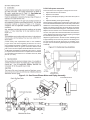
PS770 Series
Gas
Domestic
ENGLISH
P/N 59026
July 1, 2012 Rev. D
PS770 Series Gas Ovens
Model:
• PS770G Gas
Combinations:
• Single Oven
• Double Oven (Two-Stack)
• Triple Oven (Three-Stack)
OWNER'S OPERATING AND
INSTALLATION MANUAL
for domestic and standard export ovens
©2012 Middleby Marshall Inc.
is a registered trademark of Middleby Marshall, Inc. All rights reserved.
Middleby Cooking Systems Group • 1400 Toastmaster Drive • Elgin, IL 60120 • (847)741-3300 • FAX (847)741-4406
2
3
Model No.
Modéle No.
Serial No.
Serié No.
Installation Date
Date d'installation
MIDDLEBY MARSHALL
PAPA JOHN’S No Quibble Limited
Warranty
MIDDLEBY MARSHALL INC.
OVEN LIMITED WARRANTY
(Non U.S.A.)
The Seller warrants equipment manufactured by it to be free from
defects in material and workmanship for which it is responsible. The
Seller’s obligation under this warranty shall be limited to replacing or
repairing, at Seller’s option, without charge, F.O.B. Seller’s factory,
any part found to be defective and any labor and material expense
incurred by Seller in repairing or replacing such part. Such warranty
is limited to a period of one year from date of original installation or
15 months from date of shipment from Seller’s factory, whichever
is earlier, provided that terms of payment have been fully met. All
labor shall be performed during regular working hours. Overtime
premium will be charged to the Buyer.
Middleby Marshall will repair the equipment
24 hours a day, 365 days a year
(U.S.A. Only) PS770 WOW Oven
MIDDLEBY MARSHALL, HEREINAFTER REFERRED TO
AS “THE SELLER”, WARRANTS EQUIPMENT MANUFACTURED BY THEM TO BE FREE FROM DEFECTS
IN MATERIAL AND WORKMANSHIP FOR WHICH IT IS
RESPONSIBLE. THE SELLER’S OBLIGATION UNDER
THIS WARRANTY SHALL BE LIMITED TO REPLACING
OR REPAIRING, AT SELLER’S OPTION, WITHOUT
CHARGE, ANY PART FOUND TO BE DEFECTIVE AND
ANY LABOR AND MATERIAL EXPENSE INCURRED BY
SELLER IN REPAIRING OR REPLACING SUCH PART.
SUCH WARRANTY SHALL BE LIMITED TO THE ORIGINAL PURCHASER ONLY AND SHALL BE EFFECTIVE
FOR A PERIOD OF THREE YEARS FROM DATE OF
ORIGINAL INSTALLATION OR 42 MONTHS FROM DATE
OF PURCHASE, WHICHEVER IS EARLIER, PROVIDED
THAT TERMS OF PAYMENT HAVE BEEN FULLY MET.
This warranty is not valid unless equipment is installed,
started, and demonstrated under the supervision of a factoryauthorized installer.
Normal maintenance functions, including lubrication, adjustment of
airflow, thermostats, door mechanisms, microswitches, burners and
pilot burners, and replacement of light bulbs, fuses and indicating
lights, are not covered by warranty.
Any repairs or replacements of defective parts shall be performed by
Seller’s authorized service personnel. Seller shall not be responsible
for any costs incurred if the work is performed by other than Seller’s
authorized service personnel.
This warranty is valid only if the equipment is installed,
started, and demonstrated under the supervision of a
factory-authorized installer.
When returning any part under warranty, the part must be intact
and complete, without evidence of misuse or abuse, freight prepaid.
Normal maintenance functions, including lubrication,
cleaning, or customer abuse, are not covered by this no
quibble warranty.
Seller shall not be liable for consequential damages of any kind
which occur during the course of installation of equipment, or which
result from the use or misuse by Buyer, its employees or others of
the equipment supplied hereunder, and Buyer’s sole and exclusive
remedy against Seller for any breach of the foregoing warranty or
otherwise shall be for the repair or replacement of the equipment
or parts thereof affected by such breach.
Seller shall be responsible only for repairs or replacements
of defective parts performed by seller’s authorized service
personnel. Authorized service agencies are located in
principal cities throughout the contiguous United States,
Alaska, and Hawaii. This warranty is valid in the 50
United States and is void elsewhere unless the product
is purchased through Middleby International with warranty included.
The foregoing warranty shall be valid and binding upon Seller if and
only if Buyer loads, operates and maintains the equipment supplied
hereunder in accordance with the instruction manual provided to
Buyer. Seller does not guarantee the process of manufacture by
Buyer or the quality of product to be produced by the equipment
supplied hereunder and Seller shall not be liable for any prospective
or lost profits of Buyer.
The foregoing warranty is exclusive and in lieu of all other
warranties, expressed or implied. There are no implied
warranties of merchantability or of fitness for a particular
purpose.
THE FOREGOING WARRANTY IS EXCLUSIVE AND IN LIEU OF
ALL OTHER EXPRESS AND IMPLIED WARRANTIES WHATSOEVER. SPECIFICALLY THERE ARE NO IMPLIED WARRANTIES
OF MERCHANTABILITY OR OF FITNESS FOR A PARTICULAR
PURPOSE.
The foregoing shall be seller’s sole and exclusive obligation and buyer’s sole and exclusive remedy for any action,
including breach of contract or negligence. In no event shall
seller be liable for a sum in excess of the purchase price
of the item. Seller shall not be liable for any prospective
or lost profits of buyer.
The foregoing shall be Seller’s sole and exclusive obligation and
Buyer’s sole and exclusive remedy for any action, whether in breach
of contract or negligence. In no event shall seller be liable for a sum
in excess of the purchase price of the item.
This warranty is effective on Middleby Marshall equipment
sold on or after April 1, 2006.
© 2012 - Middleby Marshall, A Middleby Company.
The Middleby Marshall logo is a registered trademark of Middleby Marshall, A Middleby Company.
Middleby Marshall Inc. • 1400 Toastmaster Drive • Elgin, Illinois 60120-9272 U.S.A. • (847) 741-3300 • FAX: (847) 741 4406
4
Table of Contents
Page
Page
SECTION 1
IV. ASSEMBLY......................................................................10
DESCRIPTION......................................................................6
A. Base Pad, Legs, Casters, and Stacking..................10
I. OVEN USES......................................................................6
B. Restraint Cable Installation......................................10
II.OVEN COMPONENTS......................................................6
C. Conveyor Installation................................................10
A. Conveyor Motor Drive.................................................6
D. Standoff Installation.................................................11
B. Crumb Pans.................................................................6
V. FINAL ASSEMBLY.........................................................12
C. Conveyor End Stop and Rear Stop ...........................6
VI. ELECTRICAL SUPPLY.................................................12
D. Conveyor End Stop and Rear Stop ...........................6
E. Conveyor......................................................................6
Connection....................................................................13
VII. GAS SUPPLY...............................................................13
F. End Plugs.....................................................................6
A. Gas Utility Rough-In Recommendations.................13
G. Eyebrows.....................................................................6
B. Connection.................................................................14
H. Window.........................................................................6
C. Gas Conversion.........................................................14
I. Machinery Compartment Access Panel......................6
D. Propane Conversion.................................................14
J. Serial Plate....................................................................6
SECTION 3
K. Control Panel...............................................................6
OPERATION..........................................................................15
L. Gas Burner...................................................................6
I. LOCATION AND DESCRIPTION OF CONTROLS.........15
M. Blowers........................................................................6
II.NORMAL OPERATION, STEP-BY-STEP.......................16
N. Air Fingers....................................................................6
A. Daily Startup Procedure............................................16
III. OVEN SPECIFICATIONS...................................................6
B. Daily Shutdown Procedure.......................................16
A. Dimensions..................................................................6
III. ENERGY MODE.............................................................17
B. General Specifications...............................................6
IV. SCREEN ALERTS.........................................................17
C. Electrical Specifications for PS770 Gas Ovens........7
SECTION 4
D. Gas Orifice and Pressure Specifications
for PS770 Gas Ovens................................................7
MAINTENANCE.....................................................................18
I. MAINTENANCE - DAILY.................................................18
SECTION 2
INSTALLATION....................................................................7
II.MAINTENANCE - MONTHLY..........................................19
I. BASE PAD KIT..................................................................8
III. MAINTENANCE - EVERY 3 MONTHS..........................20
II.INSTALLATION KIT..........................................................9
IV. MAINTENANCE - EVERY 6 MONTHS..........................21
III.VENTILATION SYSTEM...................................................9
V. KEY SPARE PARTS KIT................................................22
A. Requirements...............................................................9
SECTION 5
B. Recommendations......................................................9
ELECTRICAL WIRING DIAGRAM........................................23
C. Other Ventilation Concerns........................................9
I. WIRING DIAGRAM, 770 GAS OVEN, 208/240V,
50/60 Hz, 1 Ph.................................................................23
5
6
7
8
ITEMQTY
P/N
DESCRIPTION
1
1
55028
STOP,BACK SIDE CONV EXT
2
1
55027
STOP,SIDE END CONV EXT
3
1
59026
OWNER'S OPERATING &
INSTALLATION MANUAL
4
1
42612
KIT,SUPPLEMENT SVC AGENCY LIST
5
1
33120-0056
PIPE,BLK 1-1/4" X 54"
6
1
22450-0130
BAG,POLY4MIL 9" X 12"W/MINI-GRIP
7
1
59155
BUSHING,HEYCO SB 1500-18
8
1
59099
Reflector
9
1
59098
Bracket, Reflector
10
1
59226
WLDMT, Bracket Reflector
11
2
48522
Spacer, 1.5" Dia X 1.125" H
12
2
19A15144
SCR, MS HH 10-32 X 1-1/4 18-8
9
10
D. STANDOFF INSTALLATION
1 Place screw, P/N 19A15144, through counter-bored hole in
standoff, P/N 48522, and screw into weld nut on rear shroud.
2.Repeat procedure for both sides.
11
Mount the new reflector bracket to the provided holes on the
front right-hand side of the oven. The reflector should be positioned just above the conveyor belt.
Using an assistant, hold both back cover switches in the closed
position. This will allow power to the photo-eye, and it will provide a red beam for aiming. Loosen one of the screws holding
the photo detector gimbal tight, allowing it to be reaimed at
the reflector. The beam should hit exactly in the center of the
reflector, then tighten the screw back down.
Note: This is MUCH easier in reduced light.
Replace all covers.
ATTACHING THE POINT OF SALE CABLE
Remove the cable (P/N 59198) from the Kit. Attach the 90
degree plug to the rear of the touchscreen display and route
the serial connector out the grommetted bottom hole and along
the gas pipe. Connect the serial connector with the cable supplied by the customer.
CONVEYOR BELT REVERSAL
Conveyor belt reversal consists of three steps:
1. Physically reversing the conveyor belt
2. Resetting direction jumper on the conveyor control board.
3. Switching the photo detector.
REVERSING THE CONVEYOR BELT
Remove the conveyor from the oven and find the master link
location. Remove master links and remove the belt from the
conveyor frame. Reassemble the belt back onto the frame (in
the reverse direction) and reinstall the master links. Replace
the conveyor assembly in the oven.
RESETTING DIRECTION JUMPER
Locate Jumper P1 on the conveyor control board. Move jumper
from terminals 1 and 2, and replace onto terminals 2 and 3.
SWITCHING PHOTO DETECTOR
Incoming electrical power lines are fed through the strain-relief
fitting, shown in Figure 2-12. The electrical supply connections
are made inside the electrical junction box. The power lines
then connect to the oven circuits through safety switches
located inside the machinery compartment and each blower
motor compartment. These switches interrupt electrical power
to the oven when the Machinery Compartment Access Panel
is opened, OR when either of the blower or rear shrouds is
removed.
Remove both rear fan belt covers, then remove the motor
cover assembly from both sides of the oven. The photo eye is
located on the front side of the left motor bracket. Disconnect
the three connecting wires, noting which color wires assemble
to the associated wires on the photo-detector. Remove the
entire photo detector bracket. Replace the assembly to the
right-hand side of the unit, mirroring the way it was assembled
on the left. Reconnect the detector wiring in the same order
it was on the left.
12
Connection
Refer to the wiring diagram inside the machinery compartment of the oven to determine the correct connections for the
electrical supply lines. Connect the supply as indicated on the
wiring diagram.
CAUTION
The terms of the oven's warranty require all start-ups, conversions and service work to be performed by a Middleby Marshall
Authorized Service Agent.
13
D. PS770 Propane conversion
Four items have to be changed, to change the oven to LP:
1. Adjust internal burner air shutters.
2. Replace main Orifices
3. Replace (and adjust) the spring in the main valve (see LP
kit)
4. Adjust modulating valve bypass settings.
Disconnect the manifold unions closest to the main burner, and
remove the manifold assemblies (four screws each). Remove the
addition four screws holding the burner cores and slide out each
burner core (leaving the ignition and sense wires connected).
Adjust the internal air shutters fully open, and replace the cores.
Replace the main orifices on the manifold assemblies with the
LP units, and replace the manifold assemblies. Reconnect the
unions. Replace the valve spring with the LP spring, and adjust
the downstream pressure to get 7″ WC.
Adjust the bypass screws in the side of each modulating valve
to approximately 1/6 turn from fully closed. If this setting is too
low, the burners will shut off when trying to modulate. If it is
too open, the unit will tend to gradually raise up in temperature
at standby.
Certain safety code requirements exist for the installation
of gas ovens; refer to the beginning of Section 2 for a list of
the installation standards. In addition, because a the oven is
equipped with casters, the gas line connection shall be made
with a connector that complies with the Standard for Connectors
for Movable Gas Appliances, ANSI Z21.69 (in U.S.A.), as well
as a quick-disconnect device that complies with the Standard
for Quick-Disconnect Devices for Use With Gas Fuel, ANSI
Z21.41 (in U.S.A.).
Figure 2-14 - Gas Burner/Blower Motor and Piping Assembly
Burner/Blower Motor
Gas Burner
14
SECTION 3 - OPERATION
C. Temperature Control/Display
D. Message Bar
E. Energy Level
Indicators
E. Energy Level
Indicators
B. Conveyor Time Setting
A. Main On/Off Button
I. LOCATION AND DESCRIPTION OF CONTROLS
A. Main On/Off Button
Turns all oven functions on or off. If the oven is below the
set point, it will rise to the set point and turn the conveyor
on. If it is turned off and the oven is above 200° F, the
blowers will remain on until the oven drops below 200° F.
B. Conveyor Time Setting
Adjusts and displays the conveyor bake time. Dual belt
ovens have two displays, single units have one.
C. Temperature Control/Display
Displays the average set point of both right and left sides
of the oven. Pressing on the display allows individual
temperature displays and adjustments.
D. Message Bar
Displays messages during oven operation.
E. Energy Level Indicators
Displays energy usage on left and right sides of the oven.
15
II. NORMAL OPERATION - STEP-BY-STEPC. Energy Mode Screen
1. Mode Two - Pressing this button allows the user to
set the amount of time that the oven allows before
shifting from energy mode 1 to energy mode 2. Setting this value to zero disables this energy mode.
2. Mode Three - Pressing this button allows the user to
set the amount of time that the oven allows before
shifting from energy mode 2 to energy mode 3. Setting this value to zero disables this energy mode.
3. Mode Four - Pressing this button allows the user to
set the amount of time that the oven allows before
shifting from energy mode 3 to oven off. Setting this
value to zero disables this energy mode.
Energy Modes
Energy Mode One - This mode is automatic, and starts
(bake time +1 minute) after the last product has entered
the oven. In this mode, the main oven blowers will lower
to 1500 RPM, while the oven maintains temperature and
belt speed.
Energy Mode Two - The oven lowers its set point by 100°
F, and stops the belt. Anytime that the oven is more than
10 degrees over its set point, the burners will completely
shut off, allowing the oven to cool and the burners are on
minimum flow. The main blowers will continue to run at
1500 RPM in this mode. Placing any article on the input
belt will cause normal operation of the oven to resume, and
bring the set point back to its original level. The belt will
resume operation once both sides of the oven are within
5° F of the set point.
Energy Mode Three - The oven will turn off completely and
shut off the circulation blowers once the oven temperature
has dropped below 200° F. Placing any article on the input
belt will cause normal operation of the oven to resume, and
bring the set point back to its original level. The belt will
resume operation once both sides of the over are within
5° F of the set point.
Energy Mode Four - This is a complete oven shut down.
Placing anything on the belt will NOT return the oven to
Operation. The ON button on the main screen has to be
pressed to restart the oven.
A. Daily Startup Procedure
1. Check that the circuit breaker/fused disconnect is in
the On position. Check that the window is closed.
The touch panel display should be lit.
2. Adjust the conveyor to the desired bake time.
3. Press the temperature button to display right and left
hand oven settings. Set temperatures as desired.
4. Press the ON button to activate the oven. The conveyor will not run, until the oven temperature has
reached the set points.
B. Daily Shutdown Procedure
1. Make certain there are no products left on the conveyor in the oven.
2. Press the ON square to turn the oven off.
3. Open the window to allow the oven to cool faster.
4. After the oven has cooled and the blowers have
turned off, the circuit breaker/fused disconnect may
be turned off.
Quick Reference – Touch Screen Controller
A. Main Screen
1. On/Off button - Used to turn oven On and Off.
2. Conveyor speed - Pressing on either the minutes
or seconds allows a new value to be input for the
conveyor speed. Split belt ovens have two inputs
(front and rear belts).
3. Oven temperature - Pressing on the set temperature
shifts the user to the oven temperature set point/
indicator screen.
4. Energy level indicators - Indicators to either side of
the screen indicate the energy input to that side of
the oven.
5. Message bar - Indicates various messages pertaining
to current oven conditions.
B. Oven Temperature/Set Point/Indicator Screen
1. Right actual temperature - Indicates current average
temperature of the right side of the oven.
2. Left actual temperature - Indicates current average
temperature of the left side of the oven.
NOTE: Right to Left temperature settings should not
exceed a differential of 20 °F.
3. Right Set point temperature - Pressing on this value
allows the user to adjust the set point for the right
side of the oven.
4. Left Set point temperature - Pressing on this value
allows the user to adjust the set point for the left side
of the oven.
5. Exit - Returns to the main screen.
16
III. QUICK REFERENCE: TROUBLESHOOTING
SYMPTOM
PROBLEM
SOLUTION
Oven will not
turn On.
No electrical power
•
Check that the circuit breaker/fused disconnect is on. Make
sure the emergenct stop button is on.
Oven will not
heat.
No gas pressure
•
Make sure main gas is on.
Burner did not light
•
Turn oven off, and restart. If it still does not light, call for
service.
Oven is operating, but little
or no air is coming from
the fingers.
Air fingers may be assembled incorrectly after
cleaning.
•
Turn oven off, and allow to cool. Reassemble fingers correctly.
Conveyor will not move.
Oven is not up to operating
temperature.
•
Allow oven to preheat.
Conveyor may be jammed.
•
Turn oven off, and allow to cool. Check conveyor for blockage.
SCREEN ALERTS
SYMPTOM
PROBLEM
Battery Symbol in the
lower right hand corner
The internal battery needs
to be replaced to retain
energy mode timings.
•
A qualified service technician should accomplish this.
Clean and replace the
front fan filters.
•
Failure to do this will eventually shut down the oven due to
excessive temperature.
The computer has
detected a problem with
either the main, or burner
blowers.
•
This should be corrected by a qualified service technician.
High Control Compartment
Temperature
Main Blower problem
or Combustion Blower
problem.
SOLUTION
17
18
19
20
E. Blower Belts
1. To gain access to each blower belt compartment remove
the four screws shown in Figure 4-8. Then, lift the rear
shroud off its hangers.
If access to the blower motors is required, remove the
three mounting screws (two on the front of each shroud
and one on the rear). Then, lift the end shroud straight up
and off its hangers.
2. Check each blower belt for cracking or excessive wear.
3. Check for amount of belt deflection in the center of the
belt, 1/2″ deflection is acceptable, see Figure 4-9.
4. If necessary, replace belt.
IV. MAINTENANCE - EVERY 6 MONTHS
A. Check that the oven is cool and the power is disconnected
as described in the warning at the beginning of this Section.
B. For gas ovens, clean and inspect the burner nozzel and
electrode assembly.
C. Check (and clean, if necessary) the oven venting system.
D. Check the conveyor drive shaft bushings and spacers.
Replace the components if they are worn.
Figure 4-9 - Belt Deflection
21
ITEM QTY.
1
P/N
DESCRIPTION
1
1
61561
DISPLAY, GT32 COLOR
2
1
58678
MOTOR, CONVEYOR DRIVE
3
1
58679
CONVEYOR CONTROL BOARD
4
2
59169
INVERTER, PROGRAMMED
5
1
M9608
POWER SUPPLY
6
1
59047
KIT, THERMOCOUPLE (5 THERMOCOUPLES)
7
2
M9616
FAN, COOLING
8
2
57288
MOTOR, BLOWER
9A
1
60837
AIR SWITCH BURNER/BLOWER MOTOR
9B
2
60598
SWITCH, AIR .13″ WC
10
1
54727
IGNITION MODULE
11
1
M9887
ASSEMBLY, BURNER BLOWER/MOTOR
12
2
60539
VALVE, MODULATING GAS, 1/2"
13
2
31651
AMPLIFIER, MODULATING VALVE
14
1
33983
HIGH LIMIT CONTROL MODULE, 240V
15
2
32108
TRANSFORMER, 240Vp:24Vs
16
1
59082
PLC MODULE, PROGRAMMED
17
1
58668
THERMOCOUPLE MODULE
18
1
58669
CURRENT MODULE
19
1
59112
PHOTOCELL
2
3
4
5
9
15
16, 17, 18
19
22
10
Middleby-Marshall Model Number G208-240 volt 50/60 Hz, 1 Phase
54745 Rev. J
Wiring Diagrams (electrical schematics)
23