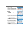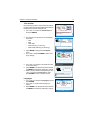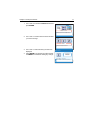
1
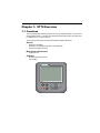
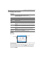
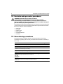
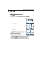
ST70 Autopilot
Controller
User Reference
Guide
Document reference: 81288-2
Date: May 2010
ii
iii
Preface
Contents
Warnings and cautions
WARNING: Product installation & operation
This equipment must be installed, commissioned and operated in
accordance with the Raymarine instructions provided. Failure to
do so could result in personal injury, damage to your boat and/or
poor product performance.
CAUTION:
Before commissioning the SmartPilot X system, check that
individual components are the correct voltage for your boat’s
supply.
As correct performance of the boat’s steering is critical for safety,
we STRONGLY RECOMMEND that an Authorized Raymarine
Service Representative fits this product. You will only receive full
warranty benefits if you can show that an Authorized Raymarine
Service Representative has installed and commissioned this
product.
WARNING: Electrical safety
Make sure you have switched off the power supply before you start
installing this product.
WARNING: Navigational safety
Although we have designed this product to be accurate and
reliable, many factors can affect its performance. Therefore, it
should serve only as an aid to navigation and should never replace
commonsense and navigational judgement. Always maintain a
permanent watch so you can respond to situations as they
develop.
Electromagnetic Compatibility (EMC) conformance
Raymarine equipment and accessories conform to the appropriate Electromagnetic
Compatibility (EMC) regulations for use in the recreational marine environment.
Correct installation is required to ensure that EMC performance is not compromised.
Always check the installation before going to sea to make sure that it is not affected by
radio transmissions, engine starting or other forms of interference.
To do this:
1. Turn on all transmitting equipment (radar, VHF radio, etc).
2. Check that all electronic systems are unaffected by interference from the transmitting equipment.
iv
EMC installation guidelines
Raymarine equipment and accessories conform to the appropriate Electromagnetic
Compatibility (EMC) regulations. This minimizes electromagnetic interference
between equipment, which could otherwise affect the performance of your system.
Correct installation is required to ensure that EMC performance is not compromised.
For optimum EMC performance, we make the following recommendations:
•
•
•
•
•
Place Raymarine equipment and cables at least 3 ft (1 m) from any equipment that
transmits, or cables that carry, radio signals from VHF radios, cables and antennas. In the case of SSB radios, the distance should be increased to 7 ft. (2 m).
Place Raymarine equipment and cables more than 7 ft (2 m) from the path of a
radar beam. A radar beam can normally be assumed to spread 20 degrees above
and below the radiating element.
Use a power source separate from that used for engine-start. This is important to
prevent erratic behavior and data loss which can occur if the engine-start does not
have a separate battery.
Use Raymarine-specified cables.
Do not cut or extend cables unless doing so is detailed in the installation manual.
Remember
Where constraints on the installation prevent any of the above recommendations:
•
Always allow the maximum separation possible between different items of electrical equipment.
This will provide the best conditions for good EMC performance of the installation.
Suppression ferrites
Raymarine cables may be fitted with suppression ferrites. These are necessary for
correct EMC performance. Any ferrite removed during installation must be replaced
as soon as installation is complete.
Use only ferrites of the correct type, supplied by Raymarine authorized dealers.
Connections to other equipment
If Raymarine equipment is to be connected to other equipment using a cable not
supplied by Raymarine, a Raymarine suppression ferrite MUST always be attached
to the cable near the Raymarine unit.
General cabling guidelines
• Do not mix AC and DC cables.
• Adhere to EMC guidelines (above).
• Use Kopex conduit where appropriate to protect cables.
• Label all cables for easy identification.
• Keep fluxgate compass cable separate from other cables.
Preface
v
EMC Servicing and maintenance
•
•
Undue noise and interference may be a symptom of an EMC-related problem.
Please report any EMC-related problem to your nearest Raymarine dealer. We
use such information to improve our quality standards.
To minimize any EMC related problems and ensure the best possible performance from your Raymarine equipment, follow the guidelines given in the installation instructions.
Product disposal
Waste Electrical and Electronic (WEEE) Directive
The WEEE Directive requires the recycling of waste electrical and electronic
equipment.
Whilst the WEEE Directive does not apply to some of Raymarine's products,
we support its policy and ask you to be aware of how to dispose of this product.
The crossed out wheelie bin symbol, illustrated above, and found on our products
signifies that this product should not be disposed of in general waste or landfill.
Please contact your local dealer, national distributor or Raymarine Technical Services
for information on product disposal.
Further assistance
Comprehensive customer support is available online and by telephone.
www.raymarine.com
In the Customer Service area you will find:
•
•
•
•
Frequently Asked Questions (FAQs).
Servicing information.
Email access to the Raymarine Technical Support Department.
Details of Raymarine agents worldwide.
Telephone helpline
In the USA
+1 603 881 5200 extension 2444
In the UK, Europe, the Middle East or the Far East
+44 (0) 23 9271 4713 (voice)
+44 (0) 23 9266 1228 (fax)
Help us to help you
When requesting service, please quote as much of the following product information
as possible:
•
•
•
•
Product type
Model number
Serial number
Software issue number
vi
Product documents
The following documents are available from www.raymarine.com/handbooks to
help you install and operate an autopilot system based around the SPX SmartPilot:
Document
Part number
ST70 Autopilot Controller User Reference Guide (this
document). Supplied with the ST70 Autopilot Controller.
81288
ST70 Pilot Operating Guide. Supplied with the ST70
autopilot controller.
81289
SPX System Installation Guide. Professional installers 87072
should use this guide to ensure safe and effective set up
of an SPX SmartPilot system.
ST70 Autopilot Controller/SmartPilot X Commission- 81287
ing Instructions. Following installation, this document,
which is supplied with your autopilot controller, must be
used to commission your autopilot system before it can
be used safely.
SeaTalkng Reference Manual. This provides detailed
information regarding SeaTalkng connectivity.
81300
Product installation guides. Separate installation
sheets are provided with individual components of the
autopilot system including the compass, rudder reference sensor, controller and drive
To the best of our knowledge, the information in the product documents was correct
when they went to press. However, Raymarine cannot accept liability for any
inaccuracies or omissions in product documents.
In addition, our policy of continuous product improvement may change specifications
without notice. Therefore, Raymarine cannot accept liability for any differences
between the product and the accompanying documents.
Contents
Contents
Chapter 1:ST70 Overview ................................................................................ 1
1.1 Functions ............................................................................................... 1
1.2 Display and controls ............................................................................... 2
Controls.................................................................................................. 2
Display ................................................................................................... 2
1.3 Operating principles ............................................................................... 3
1.4 System functionality ............................................................................... 4
1.5 Commissioning requirement .................................................................. 4
Chapter 2:Setup Procedures ........................................................................... 5
2.1 Using the menu navigation keys ............................................................ 5
2.2 Dockside and open water procedures .................................................... 6
2.3 General setup procedures ..................................................................... 6
Display settings ...................................................................................... 7
Autopilot calibration .............................................................................. 12
Diagnostics........................................................................................... 12
2.4 Response Levels ................................................................................. 14
2.5 Sailboat setup procedures ................................................................... 15
Auto Tack Angle.................................................................................... 15
Gybe Inhibit .......................................................................................... 15
Wind Trim ............................................................................................. 16
Wind Selection ..................................................................................... 16
2.6 Power boat and fishing boat setup procedures ..................................... 17
Patterns................................................................................................ 17
Chapter 3:Operating instructions ............................................................... 19
3.1 SmartPilot Functions ........................................................................... 19
Extended systems ................................................................................ 20
3.2 Menu structure ..................................................................................... 20
Sailboat menus..................................................................................... 20
Power and fishing boat menus.............................................................. 21
3.3 Pilot view .............................................................................................. 22
Setting the default Pilot View ................................................................ 22
Changing the Pilot View........................................................................ 22
3.4 Using the SmartPilot to steer your boat ................................................ 23
Engaging a tiller drive ........................................................................... 23
Steering automatically to a heading? .................................................... 23
Returning to hand steering.................................................................... 23
Changing course in Auto mode............................................................. 23
Dodging an obstacle and then resuming course ................................... 23
3.5 Using preset patterns ........................................................................... 24
3.6 Following a route set on a Chartplotter (Track mode) ........................... 24
Activating Track mode .......................................................................... 25
Leaving Track mode ............................................................................. 26
Cross track error ................................................................................... 27
Tidal stream compensation................................................................... 28
Using Dodge in Track mode.................................................................. 28
Waypoint arrival.................................................................................... 28
Steering to the next waypoint in a route................................................. 29
Skipping a waypoint (SeaTalk chartplotters only) .................................. 29
vii
viii
ST70 Pilot Controller Reference Guide
Waypoint Advance warning .................................................................. 30
Route completion.................................................................................. 30
3.7 Using the SmartPilot with sail boats ..................................................... 31
Using Wind Vane mode......................................................................... 31
What is Wind Vane mode? .................................................................... 31
Selecting Wind Vane mode ................................................................... 31
Adjusting the locked wind angle ............................................................ 31
Leaving Wind Vane mode ..................................................................... 31
True and apparent wind ........................................................................ 31
WindTrim .............................................................................................. 32
Dodging an obstacle in Wind Vane mode .............................................. 32
Wind Shift warning................................................................................ 32
Using AutoTack in Wind Vane mode ..................................................... 32
Operating hints for Wind Vane mode..................................................... 33
Preventing accidental gybes................................................................. 33
Chapter 4:Maintenance and troubleshooting .......................................... 35
4.1 Maintenance ........................................................................................ 35
Servicing and safety ............................................................................. 35
Instrument cleaning .............................................................................. 35
Cabling ................................................................................................. 35
4.2 Troubleshooting ................................................................................... 36
First considerations .............................................................................. 36
Procedures........................................................................................... 36
Using the About Display feature............................................................ 39
Technical support.................................................................................. 40
Chapter 5:Alarms .............................................................................................. 43
Chapter 6:Data List .......................................................................................... 45
Chapter 7:Vessel Settings ............................................................................. 47
Chapter 8:Technical specifications ............................................................ 49
1
Chapter 1: ST70 Overview
1.1 Functions
The ST70 Autopilot controller is used to control your autopilot system. It can be used
with Raymarine SPX, S1, S2 and S3 SmartPilot systems (although it cannot be used
to calibrate an S1, S2 or S3 system).
The functions of the ST70 controller are tailored to different situations:
General
•
•
•
Steering to a heading
Steering to a waypoint (using GPS or a chartplotter)
Power / emergency steering
Motor boats and fishermen
•
Trolling for fish
Sailboats
Maintain a fixed point of sail
Auto tacking
DODGE
TRACK
+1
--1
STANDBY
AUTO
--10
CANCEL
MENU
+10
ENTER
D10821-1
•
•
2
ST70 Pilot Controller Reference Guide
1.2 Display and controls
Controls
STANDBY
When in Standby mode:
- Press momentarily to display the Brightness popup.
- Hold down to power off.
When in Auto mode: Press momentarily to put unit in standby
DODGE
Activate Dodge mode.
TRACK
Activate Track mode.
AUTO
Activate Auto mode.
MENU
Open the control menus.
< / -1
When in Pilot mode: -1° (port)
When in Menu mode: Cursor LEFT /decrease value (hold to decrease automatically)
> / +1
When in Pilot mode:+1° (starboard)
When in Menu mode: Cursor RIGHT/increase value (hold to increase automatically)
CANCEL / -10
When in Pilot mode: -10° (port)
When in Menu mode: Cancel and go back a step without making any
changes
ENTER / +10
When in Pilot mode: +10° (starboard)
When in Menu mode: Accept value and go back a step
Display
Menu mode
To choose option 1
press
Menu Title
1
To choose option 3
press
2
3
Selected option
Information box
Press ENTER to select
D10031-1
i
Each setup menu provides a number of options. Use the < and > buttons to set a value
or change the option.
When a menu selection results in a setup page, use the < and > buttons to set the
value or make the selection that you want. Press ENTER to confirm your choice.
If at any time during setup you want to leave a setup function without making any
changes, press CANCEL.
Chapter 1: ST70 Overview
3
Auto mode
The ST70 Pilot can display current pilot data in one of three ways:
•
Heading
225
•
D10931-1
Mag
2D - Compass rose
N
19.1
TWS KTS
6.2
W
E
Depth M
S
14.8
M
D10935-1
SOG KTS
• 3D - Isometric
Refer to Section 3.3, Pilot view.
N
M
6.2
14.8
TWS KTS
Depth M
SOG KTS
D10930-1
19.1
1.3 Operating principles
The ST70 Pilot has two main modes of operation: Standby and Auto.
With the ST70 in Standby, the helm is free for manual steering and all setup functions
and calibrations can be performed. These settings are stored in the Course
Computer.
When in Auto mode, manual steering is not possible and the autopilot drives the helm.
First use after installation
When the ST70 Pilot controller is first switched on after installation it will require
commissioning.
Details of how to set these values and commission the Pilot are given in the ST70
Autopilot Controller/SmartPilot X Commissioning Instructions.
Note: The values set during initial setup can be changed subsequently via the Main Menu.
Normal operation
Detailed operating instructions are given in the ST70 Pilot Operating Guide.
4
ST70 Pilot Controller Reference Guide
Setup procedures
Setup procedures are carried out during Commissioning to set:
• Language
• Vessel Type
• Time format
• Date format
• Method used for ground wind calculation
• Magnetic variation
• Response rate
If you need to change any of these after the pilot has been commissioned, refer to the
appropriate procedure in the ST70 Autopilot Controller/SmartPilot X Commissioning
Instructions.
1.4 System functionality
Your ST70 Pilot is fitted with Raymarine SeaTalkng connectors, but it can be
connected to any of the following Raymarine systems, using suitable adaptor cables
as necessary:
•
•
•
SeaTalk
SeaTalk2
SeaTalkng
SeaTalkng
When connected to a SeaTalkng system, the ST70 Pilot repeats the data on the bus.
Power protocol
Power to the ST70 Pilot can be switched on and off using the power button. However,
where a Pilot is part of a system, it may be more convenient to switch power for the
entire system from a central circuit breaker.
In this case, when system power is switched ON again:
•
•
An ST70 Pilot that was switched on when power was last switched off will return to
the switched ON state.
An ST70 Pilot that was OFF when system power was last switched OFF will
remain OFF and will need to be switched ON using the power button.
1.5 Commissioning requirement
WARNING: The ST70 Pilot must be prepared for use in accordance with
the Commissioning Procedures, before it is used for operational purposes.
Failure to comply with this could result in death, personal injury, damage
to your boat and/or poor product performance.
5
Chapter 2: Setup Procedures
Many operating parameters are set during commissioning and may not need to be
changed again. However, if any of these parameters are not as you want them, you
can change:
• The response levels of the pilot.
• The language.
• The time/date format.
Refer to the ST70 Autopilot Controller/SmartPilot X Commissioning Instructions for
the appropriate procedures.
Other setup procedures may be useful on a day-to-day basis. These include:
•
•
•
•
•
•
Changing the screen brightness level. See Brightness on page 7.
Changing the screen colors.See Colors on page 7.
Changing data units. See Units on page 8.
Setting local time. See Time and date on page 9.
Auto Tack Angle (sailboats only). See Auto Tack Angle on page 15.
Enable or disable Gybe Inhibit (sailboats only). See Gybe Inhibit on page 15.
2.1 Using the menu navigation keys
Use the MENU key to enter the menu system.
Use the < and > keys to:
• scroll to the required option or setting.
• increase or decrease a setting.
Use the ENTER key to:
• select a menu option.
• accept a setting and exit to the previous screen.
Use the CANCEL key to exit to the previous screen without changing anything.
When you have made the changes you require, press CANCEL as many times as
required to exit to the Pilot View screen.
6
ST70 Pilot Controller Reference Guide
2.2 Dockside and open water procedures
WARNING: Dockside and open water procedures.
The ST70 Pilot must be prepared for use in accordance with the
Commissioning Procedures before it is used for operational purposes.
Failure to comply with this could result in death, personal injury, damage to
your boat and/or poor product performance.
The following procedures are described in the ST70 Autopilot Controller/SmartPilot X
Commissioning Instructions and should be performed in the prescribed order when
there is any change in vessel configuration:
•
•
•
•
•
•
Vessel type
Drive type
Rudder check
Motor check
Compass calibration
Auto learn.
2.3 General setup procedures
The setup procedures available depend on the vessel profile as set up during
commissioning (Fishing, Sail or Power), and whether the ST70 Pilot is in Standby or
Auto mode.
Procedure
Sail
Fishing
Power
Pilot view (see Pilot view on page 22)
x
x
x
Display settings (see Display settings on page 7)
x
x
x
Autopilot calibration (refer to the ST70 Autopilot Controller/
SmartPilot X Commissioning Instructions)
x
x
x
Diagnostics (see Diagnostics on page 12)
x
x
x
Response level (see Response Levels on page 14)
x
x
x
Sailboat settings (see Sailboat setup procedures on
page 15):
Auto Tack
Gybe Inhibit
Wind Trim
x
x
x
Patterns (see Power boat and fishing boat setup procedures
on page 17)
Chapter 2: Setup Procedures
1. Press MENU.
2. Use < and > to scroll to the Display Settings
screen and press ENTER.
3. Use < and > to scroll to the setting you want to
change.
Main Menu
Display Settings
Press ENTER to select.
Brightness
D9328-1
Display settings
7
Display Settings
1. Use < and > to scroll to the Brightness box and
press ENTER.
Brightness
Adjust the display brightness.
Press ENTER to select.
Brightness
100
%
< & > adjust brightness. CANCEL
i exits without saving.
Press ENTER to accept.
Colors
D10815-1
2. Use < and > to adjust the screen to the required
brightness.
• A momentary press will increment the
brightness by 10%.
• Press and hold for fine adjustment.
3. Press ENTER to accept the new value and exit,
or CANCEL to exit without making any change.
D10814-1
i
Display Settings
There are a number of options available for day
and night use.
Colours
i
Select the display colour palette.
Press ENTER to select.
D10816-1
1. Use < and > to scroll to the Colors box and
press ENTER.
2. Use < and > to select the required color
scheme.
3. Press ENTER to accept the new value and exit,
or CANCEL to exit without making any change.
8
ST70 Pilot Controller Reference Guide
Units
Display Settings
1. Use < and > to scroll to the Units box and press
ENTER.
Units
Change the default unit settings.
D10839-1
i
Press ENTER to select.
Units
Speed
Distance
Depth
Wind Speed
Heading
Flow Rate
Temperature
Press ENTER to continue
Units
Wind Speed Units
Press ENTER to select.
D10918-1
3. Press ENTER to display the Units menu.
4. Use < and > and press ENTER to select a unit to
change. These are:
• Speed (knots, mph, km/h)
• Distance (nm, statute miles, km)
• Depth (metres, feet, fathoms)
• Wind speed (knots, metres/sec)
• Heading (true, magnetic)
• Flow rate (galls/hr, liters/hr)
• Temperature (°C, °F)
5. Use < and > to scroll to the required setting.
6. Press ENTER to accept the new value and exit,
or CANCEL to exit without making any change.
7. When you have finished setting the units, use <
and > to scroll to the Continue box, then press
ENTER to return to the pilot screen.
These are your current settings.
D9439-1
i
KTS
NM
FT
KTS
M
G/H
o
C
Wind Speed Units
KTS
Use < & > to adjust.
i CANCEL exits without saving.
Press ENTER to accept
D9442-1
2. The summary box shows the current settings.
Press ENTER to display the second page of
settings.
Chapter 2: Setup Procedures
Time and date
9
Display Settings
Note that only if a GPS is connected to the system,
the time, date and time offset will be retrieved from
the GPS and cannot be changed here.
Time & Date
Press ENTER to select.
2. The summary box shows the current settings.
These are:
• Time
• Date
• Time offset
• Time format (12- or 24-hour)
• Date format (dd/mm/yy or dd/mm/yy)
3. Press ENTER to display the Time & Date
menu.
4. Use < and > and press ENTER to select a setting to change.
D10838-1
Change the default time and
i date settings.
Time & Date
Time
11:01:03
Date
14/06/07
Time Offset
-1 Hrs
TimeFormat
24-hour
Date Format dd/mm/yy
i
These are your current settings.
Press ENTER to continue
D9424-1
1. Use < and > to scroll to the Time & Date box
and press ENTER.
Time & Date
Press ENTER to select
Set date format
dd/mm/yy
< & > to adjust.
Press ENTER to accept
Languages
1. Use < and > to scroll to the Languages box and
press ENTER.
2. Use < and > to scroll to the language you
require.
3. Press ENTER to accept the new value and exit,
or CANCEL to exit without making any change.
D9542-1
i CANCEL exits without saving.
Advanced Options
Language
Press ENTER to select.
D10826-1
5. Use < and > to increase or decrease the value
or choose a setting.
6. Press ENTER to accept the new value and exit,
or CANCEL to exit without making any change.
7. When you have finished making changes, use
< and > to scroll to the Continue box, then
press ENTER to return to the pilot screen.
D9544-1
Set date format
10
ST70 Pilot Controller Reference Guide
Data Boxes
You can define which data are displayed in each of the three data boxes in the 2D and
3D pilot views.
The data that can be displayed (providing it is available) is:
Data
Display
Depth + offset
Depth
Cross Track Error
XTE
Distance to waypoint
DTW
Bearing to waypoint
BTW
Apparent wind angle
AWA
Apparent wind speed
AWS
True wind speed
TWS
True wind angle
TWA
Course over ground
COG
Speed over ground
SOG
Speed
Speed
Average Speed
Average Speed
Log
Log
Trip log
Trip
Sea Temperature
Sea Temp.
Time of day
Time
Date
Date
Heading
Heading
Chapter 2: Setup Procedures
1. Use < and > to scroll to the Data Boxes box and
press ENTER.
11
Display Settings
Data Boxes
Select data for the data boxes.
Press ENTER to select.
2. Use < and > to scroll to the box whose contents
you want to change.
D10818-1
i
Data Boxes
Box 1
Select the data for box 1.
Press ENTER to select.
Data Boxes
SOG
i
Select data to be shown.
Press CANCEL to exit without saving.
Press ENTER to select.
D10934-1
3. Use < and > to select the data you want to be
displayed.
4. Press ENTER to accept the new value and exit,
or CANCEL to exit without making any change.
D10817-1
i
12
ST70 Pilot Controller Reference Guide
Display Response
The response setting determines the rate at which data readings update. You can
adjust the response at each pilot head to best suit the conditions under which you are
operating. You can independently adjust the response at each pilot head for individual
data types:
•
•
•
•
•
•
1.
Speed
Depth
Heading
Wind Speed
Wind Angle
Use < and > to scroll to the Response box and
press ENTER.
Display Settings
Response
Select display response.
Press ENTER to select.
2. Use < and > to scroll to the response parameter
you want to change.
D10822-1
i
Response
Press ENTER to select.
3. Use < and > to increase or decrease the setting
as required, from 1 to 15, where 1 is slow and 15
is fast. You may have to experiment to find out
the appropriate response level for your vessel.
4. Press ENTER to accept the new value and exit,
or CANCEL to exit without making any change.
D10836-1
Speed
Speed
12
Press ENTER to accept.
Autopilot calibration
Refer to the ST70 Autopilot Controller/SmartPilot X Commissioning Instructions.
Diagnostics
Use < and > to scroll to the Diagnostics box and press ENTER.
D10837-1
< & > adjust response level.
i CANCEL exits without saving.
Chapter 2: Setup Procedures
About Display
There are a number of parameters of which you may need to make a note if you
experience problems with the pilot controller.
1. Use < and > to scroll to the About Display box and press ENTER.
2. A list of current display parameters is displayed. These are:
• Software, hardware and bootcode versions
• Temperature
• Volts
• Peak volts
• Current
• Peak current consumption
• Run time
3. Press ENTER or CANCEL to exit.
Display Self Test
For factory use only.
13
14
ST70 Pilot Controller Reference Guide
2.4 Response Levels
The response level controls the relationship between course keeping accuracy and
the amount of helm/drive activity. You can make temporary changes to response
during normal operation, as described in Chapter 3:Operating instructions .
Setting the Response level determines how quickly the pilot responds to a change in
conditions.
Setting
Options
Levels1 to 3
Minimize the amount of pilot activity. This conserves power, but may
compromise short-term course-keeping accuracy
Levels 4 to 6
Should give good course keeping with crisp, well controlled turns
under normal operating conditions
Levels7 to 9
give the tightest course keeping and greatest rudder activity (and
power consumption). This can lead to a rough passage in open
waters as the SPX system may ‘fight’ the sea.
1. Press MENU, then use < and > to scroll to the
Response Level screen and press ENTER.
Main Menu
Press ENTER to select.
Response Level
5
i
Response level determines how quickly
the pilot responds to heading error.
Press ENTER to accept.
D10835-1
2. Use < and > to increase or decrease the setting
as required, from 1 to 9, where 1 is slow and 9 is
fast. You may have to experiment to find out the
appropriate response level for your vessel.
3. Press ENTER to accept the new value and exit,
or CANCEL to exit without making any change.
D10832-1
Response Level
Chapter 2: Setup Procedures
15
2.5 Sailboat setup procedures
Auto Tack Angle
Sailboat Settings
1. Press MENU, then use < and > to scroll to Autopilot Calibration and press ENTER.
Auto Tack Angle
2. Use < and > to scroll to Vessel Settings and
press ENTER.
3. Use < and > to scroll to Sailboat Settings and
Press ENTER to select.
press ENTER.
4. Use < and > to scroll to Auto Tack Angle and press ENTER.
5. Use < and > to increase or decrease the auto
Auto Tack Angle
tack angle.
6. Press ENTER to accept the change or CANCEL
90
to exit without making any changes.
D10861-1
The Auto Tack Angle feature allows you to specify
the angle through which the vessel will tack when
you select Auto Tack.
Press ENTER to select.
D10860-1
Auto Tack sets the angle that the
i vessel will tack through.
Gybe Inhibit
1. Press MENU, then use < and > to scroll to AutoGybe Inhibit
pilot Calibration and press ENTER.
2. Use < and > to scroll to Vessel Settings and
press ENTER.
3. Use < and > to scroll to Sailboat Settings and
Press ENTER to select.
press ENTER.
4. Use < and > to scroll to Gybe Inhibit and press ENTER.
5. Use < and > to enable or disable gybe inhibit.
Gybe Inhibit
6. Press ENTER to accept the change or CANCEL
to exit without making any changes.
D10857-1
Sailboat Settings
Disable
i
Enable or disable gybe.
Press ENTER to select.
D10856-1
Gybe inhibit prevents an accidental gybe. The
default setting is enabled, but you can disable the
feature if required.
16
ST70 Pilot Controller Reference Guide
Wind Trim
1. Press MENU, then use < and > to scroll to
Autopilot Calibration and press ENTER.
2. Use < and > to scroll to Vessel Settings and
press ENTER.
3. Use < and > to scroll to Sailboat Settings and
press ENTER.
4. Use < and > to scroll to Wind Trim and press
ENTER.
5. Use < and > to increase or decrease the auto
tack delay.
6. Press ENTER to accept the change or CANCEL
to exit without making any changes.
Sailboat Settings
Wind Trim
Press ENTER to select.
D10853-1
Wind Trim controls the sensitivity of the pilot when
steering in wind vane mode.
Wind Trim
5
Press ENTER to select.
D10852-1
Set the response to wind
i direction changes
Wind Selection
Wind Selection
Press ENTER to select.
D10855-1
1. Press MENU, then use < and > to scroll to
Autopilot Calibration and press ENTER.
2. Use < and > to scroll to Vessel Settings and
press ENTER.
3. Use < and > to scroll to Sailboat Settings and
press ENTER.
4. Use < and > to scroll to Wind Selection and
press ENTER.
5. Use < and > to switch between True and Apparent.
6. Press ENTER to accept the change or CANCEL
to exit without making any changes.
Sailboat Settings
Wind Selection
True
i
Select wind source.
Press ENTER to select.
D10854-1
You can specify whether the wind source is to be
true or apparent when steering in wind vane mode.
Chapter 2: Setup Procedures
17
2.6 Power boat and fishing boat setup procedures
Patterns
A number of sailing patterns are provided, each with one or more parameters which
can be set to the desired value.
Main Menu
All Patterns
Press ENTER to select.
Pattern
Settings
Circle
Direction (port or starboard) and radius
Zigzag
Direction (port or starboard), Angle and Length
Cloverleaf
Direction (port or starboard)
Radius
Spiral
Direction (port or starboard)
Radius
Radius Increment
On Heading Radius
On Heading Increment
Circle against heading
Direction (port or starboard) and Distance
Figure of eight
Direction (port or starboard) and Radius
Pattern Search
Direction (port or starboard)
Width
Height
Increase Width
Increase Height
Box Search
Direction (port or starboard), Width, Height
180° Turn
Direction (port or starboard) and Radius
D10929-1
1. Press MENU, then use < and > to scroll to All
Patterns and press ENTER.
2. Use < and > to scroll to the required pattern,
then press ENTER to accept or CANCEL to
exit.
3. When you select a pattern, the settings for that
pattern will be displayed. The available preset
patterns and their settings are:
The preset patterns and the settings you can
specify are:
18
ST70 Pilot Controller Reference Guide
19
Chapter 3: Operating instructions
The SmartPilot controller is a SeaTalkng-compatible autopilot control unit. It is
designed as the main controller for the SmartPilot system.
The SmartPilot controller operates in the following modes:
•
•
•
Standby: SmartPilot off. You have manual control of the boat.
Auto: The SmartPilot steers the boat to maintain a locked heading.
Track: The SmartPilot steers the boat to maintain a track between two waypoints
created on a navigation aid.
Wind Vane: The SmartPilot steers the boat to maintain a course relative to a true
or apparent wind angle.
The SmartPilot controller also provides:
•
•
•
automatic tack (Auto Tack) in Auto and Wind Vane modes.
waypoint advance feature in Track mode.
3.1 SmartPilot Functions
The functions provided with your system depend upon the model of course
computer installed.
:
Non-G systems
(without GyroPlus)
S1G, S2G and S3G
systems
(with GyroPlus)
SPX systems
Full basic functionality
Internal GyroPlus yaw sensor
provides enhanced course
keeping using AST
(Advanced Steering Technology)
Internal GyroPlus yaw sensor
provides enhanced course
keeping using AST
(Advanced Steering Technology)
Steering to true and apparent
wind in Wind Vane mode
Steering to true and apparent
wind in Wind Vane mode
Steering to true and apparent
wind in Wind Vane mode
Equipped with AutoLearn,
Equipped with AutoLearn,
Raymarine’s self-learning cal- Raymarine’s self-learning calibration system
ibration system
Fishing patterns
Intelligent dodge
Smart Rudder Sense (SRS)
20
ST70 Pilot Controller Reference Guide
Extended systems
You can connect the SmartPilot controller to other Raymarine SeaTalk equipment
so it can send and receive SeaTalk data:
•
it can use waypoint information from a SeaTalk navigation instrument to provide
track control.
• it can use boat speed from a SeaTalk speed instrument to optimize track-keeping
performance.
• it can use wind information from a SeaTalk wind instrument for Wind Vane steering.
The SmartPilot control unit can also display data from any compatible
multifunctional display or instruments transmitting SeaTalk, NMEA0183,
NMEA2000 or SeaTalkng instrument data in a selection of data pages.
For further information on other connections to your system see ST70 Autopilot
Controller/SmartPilot X Commissioning Instructions.
3.2 Menu structure
The ST70 pilot controller menu structure varies depending on which Vessel Type
has been specified during commissioning and what data is available. For instance,
if there is no depth transponder, then no depth data will be available.
Sailboat menus
The menu options available for vessel type sailboat are:
•
•
•
•
•
•
Wind Vane Mode
Tack Starboard
Sailboat Settings (only when connected to a compatible course computer):
• Auto Tack settings
• Gybe Inhibit
• Wind Trim
• Wind Selection
• Autopilot calibration
Pilot View
Display settings:
• Brightness
• Colors
• System brightness / Color
• Units
• Time and Date
• Data Boxes
• Response
Advanced Options:
• Setup Wizard
• Language
Chapter 3: Operating instructions
•
•
•
• Vessel Type
• Boatshow Mode (simulated data - boat show use only)
• Factory Reset
Autopilot Calibration (only when connected to a compatible course computer):
• Vessel settings
• Drive settings
• Sailboat settings
• Commissioning
Diagnostics
Tack Port
Power and fishing boat menus
The menu options available for vessel types power and fishing boat are:
•
•
•
•
•
•
•
•
•
Pattern 1 (fishing boat only; only when connected to a compatible course computer)
Pattern 2(fishing boat only; only when connected to a compatible course computer)
Patterns (only when connected to a compatible course computer)
Response level
Pilot View
Display settings:
• Brightness
• Colors
• System brightness / Color
• Units
• Time and Date
• Data Boxes
• Response
Advanced Options:
• Setup Wizard
• Language
• Vessel Type
• Boatshow Mode (simulated data - boat show use only)
• Factory Reset
Autopilot Calibration (only when connected to a compatible course computer):
• Vessel settings
• Drive settings
• Commissioning
Diagnostics
21
22
ST70 Pilot Controller Reference Guide
3.3 Pilot view
The pilot display can be formatted as Plain, 2D or 3D.
Setting the default Pilot View
1. Press MENU.
2. Use < and > to scroll to the Pilot View screen and press ENTER.
3. Use < and > to scroll to the required view option.The options are:
• Heading
225
D10931-1
Mag
•
2D - Compass rose
N
19.1
TWS KTS
6.2
W
E
Depth M
S
14.8
M
D10935-1
SOG KTS
•
3D - Isometric
N
4. Press ENTER to accept the view option and exit, or
CANCEL to exit without making any change.
M
19.1
6.2
14.8
TWS KTS
Depth M
SOG KTS
1. With any operational page displayed, press and
hold MENU to display Heading View.
2. Press and hold MENU again to display the 2D Compass Rose View.
3. Press and hold MENU again to display the 3D Isometric View.
4. Press and hold MENU to cycle through the different views.
5. Release the MENU button when the view you want is displayed.
D10930-1
Changing the Pilot View
Chapter 3: Operating instructions
23
3.4 Using the SmartPilot to steer your boat
CAUTION: Maintain a permanent watch
Automatic course control makes it easier to sail a boat, but it is NOT a
substitute for good seamanship. ALWAYS maintain a permanent watch
by the helm.
Engaging a tiller drive
•
Place the pushrod over the tiller pin. If necessary, extend or retract the pushrod
using the -1, +1, -10 and +10 keys.
Steering automatically to a heading?
1. Steady the boat on the required heading.
2. Press AUTO.
The SmartPilot is now in AUTO mode and will steer to the chosen heading, shown
on the display. This mode is often known as ‘point-and-shoot’.
Returning to hand steering
Press STANDBY to disengage the SmartPilot. In STANDBY mode, you have manual
control of the boat and the display shows the boat’s current compass heading.
Changing course in Auto mode
In Auto mode, use the -1 and -10 (port) and +1 and +10 (starboard) buttons to
change the locked heading in steps of 1° or 10°. For example: press -10 three
times for a 30° course change to port.
Dodging an obstacle and then resuming course
To avoid an obstacle when your boat is under autopilot control, you can dodge the
obstacle and then resume your previous course.
Using Dodge in Auto mode
The DODGE popup will appear over whichever pilot
view you have currently selected.
DODGE
N
19.1
follow last
heading (300°)
DODGE
TWS KTS
Once you have finished steering manually you can:
•
•
Press DODGE to return to the previous heading, or
Press AUTO to continue on your new heading.
W
E
AUTO
Depth M
6.2
follow this
heading (272°)
14.8
S
SOG KTS
M
D10933-1
When in Auto mode, press DODGE.
24
ST70 Pilot Controller Reference Guide
Using Dodge in Track mode
When in Track mode, press DODGE.
19.1
DODGE
TWS KTS
•
•
Press DODGE to track from here to the next waypoint, or
Press AUTO to return to the previous track.
6.2
TRACK
Depth M
Track from here
W
E
Resume current
Track
14.8
S
SOG KTS
M
D10932-1
Once you have finished steering manually you can:
N
DODGE
The DODGE popup will appear over whichever pilot
view you have currently selected.
Note: The dodge to track feature requires a compatible multifunctional display.
3.5 Using preset patterns
Main Menu
1. Press MENU.
All Patterns
2. Use < and > to select All Patterns.
3. Use < and > to select the pattern you want to follow.
Press ENTER to select.
You can change the initial direction and various
other parameters for each pattern as required (see Patterns on page 17).
D10929-1
Preset patterns are only available for power boats
and fishing boats If the vessel type is fishing boat,
the two most recently used patterns are available
as a menu option.
3.6 Following a route set on a Chartplotter (Track
mode)
CAUTION: Safety in Track mode
Track mode provides accurate track keeping even in complex
navigational situations. However, it is still the skipper’s responsibility to
ensure the safety of their boat at all times through careful navigation and
frequent position checks. Track mode assists precise navigation and
removes the tasks of compensating for wind and tidal drift. However, you
MUST still maintain an accurate log with regular plots.
In Track mode, the SmartPilot maintains a route between waypoints created on a
navigation system. It makes any course changes necessary to keep your boat on
course, automatically compensating for tidal streams and leeway.
Chapter 3: Operating instructions
25
Waypoint arrival
Next
Waypoint
Example1:
Cross track error (XTE)
due to waypoint arrival circle
Bearing to
next waypoint
Track leg
Waypoint
arrival circle
D10922-1
XTE
Track mode is available only if you have connected the SmartPilot to a suitable
navigation system providing SeaTalk or NMEA information. (See ST70 Pilot
Controller/SmartPilot X Commissioning Instructions for connection details)
Your SmartPilot system can receive route information from:
•
•
a SeaTalk (ST1 & SeaTalkng) navigation instrument or chartplotter.
a navigation system transmitting data in NMEA 0183 or NMEA 2000 format.
Activating Track mode
CAUTION: Make suitable preparations for entering track mode
When you enter Track mode, the SmartPilot will bring the boat onto the
track in a controlled way. The closer the boat is to the correct heading
and track, the quicker it will settle the boat onto the new course. To avoid
an unexpected turn, align the boat approximately with the required track
before entering Track mode.
26
ST70 Pilot Controller Reference Guide
Start with the SmartPilot in AUTO mode and your chartplotter following a route.
1. Press TRACK to enter Track mode.
2. Wait for the warning to sound.
The display will show the bearing to the next planned waypoint and the direction in
which the boat will turn to reach this waypoint.
3. If it is safe for the boat to turn onto the new course, press the TRACK button:
• the SmartPilot will turn the boat onto the new course.
• the display will show the heading required to achieve the required track.
Waypoint arrival and advance
Next target
Waypoint at 270°
Target
Waypoint
New target
waypoint at 270°
Old target
Waypoint
N
TRACK
19.1
TWS KTS
6.2
90°
TURN TO
WAYPOINT
001
Press TRACK to accept
M
Waypoint arrival
Notes:
Waypoint advance
D10921-1
S
SOG KTS
(1)
The rate of turn when in Track mode is set using the TURN RATE calibration
setting. Adjust this as appropriate for optimum comfort.
(2) If the boat is more than 0.3 nm from the track, the Large Cross Track Error
warning will sound (see page 27).
Leaving Track mode
You can leave Track mode at any time by:
•
•
•
pressing AUTO to return to Auto mode.
pressing DODGE to perform a dodge maneuver (see Using Dodge in Track mode
on page 28).
pressing STANDBY to steer manually in Standby mode.
Chapter 3: Operating instructions
27
Cross track error
Cross track error (XTE) is the distance between the current position and a planned
track leg.
There are a number of reasons why you may have a cross track error (XTE), for
example:
•
•
•
Pressing the track button at a position some distance from the route.
Course change to avoid an obstacle.
Waypoint arrival under certain conditions (See Waypoint arrival on page 28)
CAUTION: When returning to TRACK mode the autopilot will
correct the XTE in order to keep to the defined track leg. The
direction of turn may not coincide with the bearing to waypoint
and may be different from that expected.
Course correction
Example1:
Initial turn toward waypoint
Example2:
Initial turn away from actual
waypoint position.
Target
Waypoint
Cross
track error
D10917-1
Cross
track error
Target
Waypoint
If the cross track error is greater than 0.3 nm, the SmartPilot will sound the Large
Cross Track Error warning and show whether you are to the port (Pt) or starboard
(Stb) of the planned track.
Note: The cross track error alarm will continue to display and sound until it is reduced to less
than 0.3Nm.
28
ST70 Pilot Controller Reference Guide
Tidal stream compensation
Under most conditions, the SmartPilot will hold the selected track to within ±0.05
nm (300 ft) or better. It takes account of the boat’s speed when computing course
changes to ensure optimum performance.
Waypoint 2
Boat's speed over ground
Tidal component
D10924-1
Boat's speed through water
Waypoint 1
Using Dodge in Track mode
The DODGE popup will appear over whichever pilot
view you have currently selected.
Once you have finished steering manually you can:
•
•
Press DODGE to track from here to the next waypoint, or
Press AUTO to return to the previous track.
N
DODGE
19.1
DODGE
TWS KTS
6.2
TRACK
Depth M
Track from here
W
E
Resume current
Track
S
14.8
M
SOG KTS
D10932-1
When in Track mode, press DODGE. (See Dodging an
obstacle and then resuming course on page 23)
Waypoint arrival
19.1
TWS KTS
6.2
45°
TURN TO
W
WAYPOINT
E
001
Press TRACK to accept
S
SOG KTS
This shows the new bearing to the next waypoint and
the direction the boat will turn to acquire the new track.
N
TRACK
M
D10919-1
As the boat arrives at the target waypoint the
chartplotter will select the next target waypoint and
transmit this to the SmartPilot. It will then detect the
new target waypoint name, sound a Waypoint
Advance warning and display the Waypoint Advance
popup.
Chapter 3: Operating instructions
29
Waypoint arrival circle
The NEXT WPT screen and acknowledgement occur within a circle around the
actual waypoint (and hence a distance from the next track leg). If you have
manually changed the default waypoint arrival circle value to 0.3Nm or greater this
can result in a cross track error alarm and associated course correction.
Waypoint arrival
Example1:
Cross track error (XTE)
due to waypoint arrival circle
Next
Waypoint
Bearing to
next waypoint
Track leg
Waypoint
arrival circle
D10937-1
XTE
Refer to Cross track error on page 27 for more details.
Steering to the next waypoint in a route
When the Waypoint Advance warning sounds, the SmartPilot suspends Track
mode and maintains the current boat heading.To advance to the next waypoint:
1. Check that it is safe to turn onto the new track.
2. Press the TRACK button. This will cancel the Waypoint Advance warning and turn
the boat towards the next waypoint.
Note: If you do not press TRACK to accept the Waypoint Advance, the SmartPilot will maintain
the current heading and continue sounding the warning.
Skipping a waypoint (SeaTalk chartplotters only)
If you want to advance to the next waypoint before you have arrived at the target
waypoint, you can skip a waypoint by pressing TRACK for 1 second. The display
will then show the Waypoint Advance screen for the next waypoint. Check it is safe
to turn, then press TRACK to turn the boat towards the next waypoint.
30
ST70 Pilot Controller Reference Guide
WARNING: Ensure navigation safety
Skipping a waypoint will take you straight to the next waypoint. Check
your navigation before making the turn.
Waypoint Advance warning
The SmartPilot activates the Waypoint Advance warning in Track mode whenever
the target waypoint name changes. This occurs when:
you select automatic acquisition by pressing TRACK from Auto
you request waypoint advance by pressing TRACK for 1 second in Track mode
(with SeaTalk navigators only)
• the boat arrives at the target and the navigator accepts the next waypoint
• you activate the Man Overboard (MOB) function.
When the warning sounds, the SmartPilot continues on its current heading but
displays:
•
•
• the bearing to the next waypoint
• the direction the boat will turn to take up that bearing.
To respond to a Waypoint Advance warning:
•
•
check that it is safe to turn onto the new track, then press TRACK to accept the
waypoint advance
alternatively, you can cancel the warning without accepting the waypoint advance
by pressing:
• AUTO to continue on the same heading, or
• STANDBY to return to manual control
Route completion
The SmartPilot displays the ROUTE COMPLETED warning when you have reached
the last waypoint on a route in Track mode.
Note: The ‘Route Complete’ alarm only sounds and displays in conjunction with a SeaTalk
chartplotter. NMEA chartplotters do not support the ‘Route Complete’ function, they will display
‘NO DATA’.
•
•
press AUTO to continue on the same heading.
or press STANDBY to return to manual control.
Chapter 3: Operating instructions
31
3.7 Using the SmartPilot with sail boats
Using Wind Vane mode
You can only select Wind Vane mode if the SmartPilot is receiving suitable SeaTalk
or NMEA wind direction information.
What is Wind Vane mode?
When the SmartPilot is in Wind Vane mode it uses the wind angle as the primary
heading reference. As changes in the true or apparent wind angle occur, it adjusts
the locked heading to maintain the original wind angle.
Selecting Wind Vane mode
1. Steady the boat onto the required wind angle.
2. Press MENU, then use < and > to select Wind
Vane mode and lock the current wind angle.
The display shows the locked heading (e.g.
128°) and the wind angle (e.g. WIND 145P
indicates an wind angle of 145° to port).
3. The SmartPilot will then adjust the boat’s
heading to maintain the locked wind angle.
Main Menu
Wind Vane Mode
Press ENTER to select.
D10827-1
You can select Wind Vane mode from either
Standby or Auto mode:
Adjusting the locked wind angle
You can adjust the locked wind angle by using the -1, +1, -10 and +10 buttons to
change course. For example, to bear away by 10° when the boat is on a starboard
tack:
•
•
press -10 to turn the boat 10° to port – the locked wind angle and locked heading
will both change by 10°.
the autopilot will then adjust the locked heading as required to maintain the new
wind angle.
Note: Because turning the boat affects the relationship between the true and apparent wind an-
gles, you should only use this method to make minor adjustments to the wind angle. For major
changes, return to Standby mode, steer onto the new heading, then reselect Wind Vane mode.
Refer to the ST70 Autopilot Controller User Reference Guide for the procedure for changing the
wind reference between True and Apparent.
Leaving Wind Vane mode
You can leave Wind Vane mode by:
•
•
pressing AUTO to return to Auto mode.
pressing STANDBY to return to manual control.
True and apparent wind
SmartPilots can maintain a course relative to either an apparent or true wind angle
in Wind Vane mode
32
ST70 Pilot Controller Reference Guide
The default setting is apparent wind. If required, you can change this to true wind in
User Calibration. See Wind Selection on page 16.
WindTrim
In Wind Vane mode the SmartPilot uses WindTrim to eliminate the effects of
turbulence and short term wind variations. This provides smooth and precise
performance with minimal power consumption. You can adjust the wind response
(WindTrim) level in User Calibration to control how quickly the SmartPilot responds
to changes in the wind direction. Higher wind trim settings will result in a pilot that is
more responsive to wind changes. See Wind Trim on page 16.
Dodging an obstacle in Wind Vane mode
In Wind Vane mode you still have full control from the keypad. You can make a
dodge maneuver by using the course change buttons (-1, +1, -10 or +10) to select
the desired course change.
After you have avoided the hazard, you can cancel the dodge course change by
making an equal course change in the opposite direction.
Wind Shift warning
If the autopilot detects a wind shift of more than 15° it will sound the wind shift
warning and display the WIND SHIFT message:
•
•
To cancel the warning, and retain the existing wind angle and new heading, press
CANCEL.
Alternatively, to cancel the warning and return to the previous heading:
• adjust the locked wind angle using the -1, +1, -10 and +10 buttons.
• press STANDBY to return to hand steering, steer onto the required heading,
and press CANCEL to return to Wind Vane mode with the new wind angle.
Using AutoTack in Wind Vane mode
Note: If you use the AutoTack function in Wind Vane mode, make sure the wind vane has been
centered accurately.
The SmartPilot has a built in automatic tack facility (AutoTack) that turns the boat
through a specified angle (default is 100°) in the required direction.
•
•
To AutoTack to port: press the -1 and -10 buttons together.
To AutoTack to starboard: press the +1 and +10 buttons together.
You can adjust the default AutoTack angle in User Calibration. See Auto Tack Angle
on page 15.
You can also use the menu button to select and execute the autotack option.
When you Auto Tack in Wind Vane mode, the boat turns through the Auto Tack
angle. The SmartPilot will then trim the heading to mirror the locked wind angle
from the previous tack.
Chapter 3: Operating instructions
33
Operating hints for Wind Vane mode
•
•
•
•
•
Always trim your sails carefully to minimize the amount of standing helm.
Reef the headsail and mainsail a little early rather than too late.
In Wind Vane mode the SmartPilot will react to long-term wind shifts, but will not
correct for short-term changes such as gusts.
In gusty and unsteady inshore conditions, it is best to sail a few degrees further off
the wind so that changes in wind direction can be tolerated.
Avoid using Auto Tack in conditions where the wind may shift suddenly.
CAUTION: Allow time for course changes
CAUTION: When making major course changes, the trim on the boat may
change substantially. Due to this, the SmartPilot may take some time to
settle accurately onto the new course.
Preventing accidental gybes
The gybe inhibit feature stops the boat from performing an AutoTack away from the
wind – this will prevent accidental gybes. This feature can be disabled if required.
Note: For the gybe inhibit feature to work, the SmartPilot needs suitable wind information.
With gybe inhibit on:
•
•
you will be able to perform an AutoTack through the wind.
the autopilot will prevent the boat from performing an AutoTack away from the
wind, to prevent accidental gybes.
With gybe inhibit off:
•
you can perform an AutoTack through or away from the wind.
Note: Gybe inhibit is switched on as a default but can be disabled in User Calibration. See Gybe
Inhibit on page 15.
34
ST70 Pilot Controller Reference Guide
35
Chapter 4: Maintenance and troubleshooting
4.1 Maintenance
Servicing and safety
Unless specific instructions are given to the contrary, Raymarine equipment should
be serviced only by authorized Raymarine service technicians. They will ensure that
service procedures and replacement parts used will not affect performance.
Some products generate high voltages, so never handle the cables/connectors when
power is being supplied to the equipment.
When powered up, all electrical equipment produces electromagnetic fields. These
can cause nearby electrical equipment to interact, with a possible adverse effect on
operation. To minimize these effects and enable best possible performance from your
Raymarine equipment, guidelines are given in the installation instructions.
Always report any EMC-related problem to your nearest Raymarine dealer. We use
such information to improve our quality standards.
In some installations, it may not be possible to prevent the equipment from being
affected by external influences. In general this will not damage the equipment but it
can lead to spurious resetting action, or momentarily may result in faulty operation.
Instrument cleaning
Periodically clean your ST70 autopilot controller with a soft damp cloth.
Do NOT use chemical or abrasive materials to clean your controller.
Do NOT wipe the controller with a dry cloth as this could cause scratches.
Cabling
Periodically examine all cables for chafing or other damage to the outer shield, and
where necessary, replace and re-secure
36
ST70 Pilot Controller Reference Guide
4.2 Troubleshooting
In the unlikely event that you encounter problems using your ST70 autopilot
controller, use this section to resolve the situation.
First considerations
If your ST70 is not performing as you think it should, be sure you are operating it
correctly as described in the ST70 Pilot Operating Guide.
Then:
• Ensure that any data you think may be missing is available on your boat. For
example, if you do not have a wind transducer, then there will be no wind-related
data.
• Take into account any changes that may have been made to the electrical system
aboard your boat. Such changes could affect the performance of your ST70 controller.
• Be aware that radio signals transmitted nearby (for example from another boat or
shore station) could affect the performance of your ST70 controller.
If you are satisfied that the problem is not due to any of the above, use the procedures
in this section to isolate the cause of the problem.
Procedures
If it appears that an ST70 controller is not operating satisfactorily, check the
symptoms below to determine how to resolve the problem:
• Nothing on the controller screen – refer to Figure 4-1, ST70 troubleshooting –
Chart 1 .
• Data missing from the controller screen – refer to Figure 4-2, ST70 troubleshooting – Chart 2 .
• Data on the controller screen is garbled – refer to Figure 4-3, ST70 troubleshooting – Chart 3 .
• Specific data types are missing or incorrect:
• Check the relevant Transducer and Pod, including the connections between
them and to the system.
• If speed readings are missing or obviously wrong, the speed transducer paddle wheel could be fouled and need cleaning.
Chapter 4: Maintenance and troubleshooting
37
ST70 user troubleshooting
Nothing on
screen
Chart 1
Are the pilot buttons
back-lit?
NO
YES
Is power on at any other
product in the system?*
* The system to which the instrument is connected (either
SeaTalk, SeaTALK2 or SeaTalkng )
NO
YES
Switch on power to the
system
At faulty pilot, carry out
switch-on procedure
Is problem still
present?
Are the pilot buttons
back-lit?
NO
YES
NO
Return to
normal
operation
YES
Is the display lit?
Ensure all system
connections are made
satisfactorily
NO
Check display brightness
setting and adjust as
necessary (see Operating
Guide)
Is the display lit?
YES
Is problem still
present?
Return to
normal
operation
NO
YES
NO
Use the About Display & About
System features to get
information about your products.
Return to
normal
operation
Figure 4-1 ST70 troubleshooting – Chart 1
Obtain
technical
assistance
Return to
normal
operation
D9524-1
YES
38
ST70 Pilot Controller Reference Guide
ST70 user troubleshooting
Chart 2
Data missing
Is the display lit?
Refer to Chart 1
NO
YES
Are some data types
present?
NO
YES
At 'suspect' pilot, run
the About System
diagnostic function
Are the same data
types missing from
more than one product
in the system?
Is resultant product list
empty?
NO
YES
NO
Ensure all system
connections are
satisfactory.
YES
Ensure connections to
'suspect' pilot head are
satisfactory.
Ensure connections to
relevant transducer(s)
and pod(s)are
satisfactory.
Is data present?
Is all data available?
NO
NO
YES
Use the About Display & About
System features to get
information about your products.
Return to
normal
operation
Obtain
technical
assistance
Figure 4-2 ST70 troubleshooting – Chart 2
Use the About Display & About
System features to get
information about your products.
Return to
normal
operation
Obtain
technical
assistance
D9526-1
YES
Chapter 4: Maintenance and troubleshooting
39
ST70 user troubleshooting
Garbled information
on screen
Chart 3
Are other instruments
in system working OK?
NO
YES
Ensure all system
connections are
satisfactory.
Is problem still
present?
NO
YES
Obtain
technical
assistance
Return to
normal
operation
Figure 4-3 ST70 troubleshooting – Chart 3
Using the About Display feature
The About Display function provides information about the instrument on which it is
run. Before seeking technical assistance, please use the About Display function
whenever possible to find out the relevant:
•
•
•
•
•
•
•
•
•
Software Version Number
Hardware Version Number
Bootloader Version Number
Temperature
Voltage
Peak voltage
Current
Peak current
Total hours run
D9529-1
Use the About Display & About
System features to get
information about your products.
40
ST70 Pilot Controller Reference Guide
To run the About Display function:
1. With the instrument switched on, press MENU
to display the Main Menu, then use < and > to
select the Diagnostics option.
2. Press ENTER to display the Diagnostics menu.
Main Menu
Press ENTER to select.
D10095-1
Diagnostics
D10097-1
3. With the Diagnostics menu displayed, use <
About Display
and > to select the About Display option, then
V0.20
Software Ver.
V2.00
Hardware Ver.
press ENTER. Note that:
V0.10
Bootcode Ver.
• Temperature should be in the range -30°C to
Temperature 35.20 C
12.16
V
Volts
+70°C
12.26 V
Peak Volts
• Volts should be in the range 9 V to 16 V
Current
180 mA
Peak Current 195 mA
• Peak Volts should be in the range 9 V to
125.75
Run Time
16 V
Press ENTER to select
• Current and Peak Current should be not
greater than 220 mA
4. Make a note of any data you need then press ENTER.
• If you have seen all the available data the display shows the Diagnostics
menu.
• If there is more data to be displayed, the next page of About Display data is displayed. Repeat step 4 until the display shows the Diagnostics menu.
Technical support
Raymarine provides a comprehensive customer support service, on the world wide
web and by telephone help line. Please use either of these facilities if you are unable
to rectify a problem.
If you intend seeking technical assistance, please first use the About Display and
About System functions whenever possible, and make a note of the information
available there.
Note: If it is not possible to use the About Display function on a faulty instrument, remember you
may still be able to get system information by running About System at another instrument.
World wide web
Please visit the Customer Support area of our web site at:
www.raymarine.com
As well as providing a comprehensive Frequently Asked Questions section and
servicing information, the web site gives e-mail access to the Raymarine Technical
Support Department and a details of the locations of Raymarine agents, worldwide.
Chapter 4: Maintenance and troubleshooting
41
Telephone help line
If you do not have access to the world wide web, please call the Raymarine help line.
In the USA, call:
• +1 603 881 5200 extension 2444
In the UK, Europe the Middle East or the Far East, call:
• +44 (0) 23 9271 4713 (voice)
• +44 (0) 23 9266 1228 (fax)
Help us to help you
When requesting service, please have the following product information to hand:
• Equipment type.
• Model number.
• Serial number.
• Software version.
• Hardware version.
You can find out this information by running the About Display diagnostic feature.
42
ST70 Pilot Controller Reference Guide
43
Chapter 5: Alarms
N
AUTO
OFFCOURSE
W
Steer to STARBOARD
6.2
E
Press CANCEL to silence alarm
S
SOG KTS
The following alarm functions are supported by the
ST70, although they may not all be applicable to your
system.
M
Alarm
Description
Action
Calibration required
The pilot has not been fully calibrated. This will appear for a few
seconds after initial power-up.
Self-cancelling.
Change mode.
Off course
Vessel is off course by more than
the predetermined limit. May
appear in Auto, Track and Wind
Trim modes.
Change mode.
Change course.
Reduce heading error.
Route complete
Indicates completion of a route,
when in Track mode.
Change mode.
Large Cross Track Error
The cross track error (XTE) is
greater than 0.3nm. May appear
when in Track mode or when
entering Track mode from any
other mode.
Change mode.
Data flagged as valid.
Loss of waypoint data
Loss of waypoint data
Change mode
Wind shift
Apparent wind angle has changed Change mode.
by more than 15 degrees.
Change course.
Reduction in change of wind
angle.
Auto release
Safety alarm.
Auto release (SD)
Safety alarm.
Drive stopped
Safety alarm. A rudder stall condi- Change mode.
tion has persisted for more than a Reversal of drive demand.
predetermined time, and power
has been removed from the drive
unit. May appear in Auto, Track
and Wind Trim modes.
No control head
Safety alarm.
Seatalk 1 fail
Safety alarm.
Seatalk 2 fail
Safety alarm.
EEPROM corruption
Safety alarm.
No pilot
Safety alarm.
Variable text general
alarm
Safety alarm.
No compass
Safety alarm.
Safety alarm.
D10938-1
A range of alarm functions are available, to alert you to
particular events. When an alarm occurs, a popup box
is displayed and an audible alarm indication may
sound. The popup identifies the reason for the alarm.
If an alarm occurs you can silence it by pressing
CANCEL, or switching to STANDBY (if in AUTO mode).
44
ST70 Pilot Controller Reference Guide
Alarm
Description
Rate gyro fault
Safety alarm.
Current limit
Safety alarm.
Action
Rudder feedback unit fault Safety alarm.
Autolearn fail 1 (not carried out)
Safety alarm.
Autolearn fail 2 (manual
intervention)
Safety alarm.
Autolearn fail 3 (compass Safety alarm.
or drive error)
Autolearn fail 4
Safety alarm.
Autolearn fail 5
Safety alarm.
Autolearn fail 6
Safety alarm.
Turn rate too high
Safety alarm. Indicates an exces- Change calibration stage.
sive turn rate when calibrating the Reduce turn rate.
fluxgate compass. May appear in
Calibration mode.
Low battery
No navigation data
Absence of one of the following:
Compass (Auto, Track and Wind
Trim modes).
XTE (Track mode).
Wind angle (Wind Trim mode)
MOB
Pilot start up
Waypoint advance
Waypoint advance Turn to
port
Waypoint advance Turn to
starboard
No wind data
No speed data
Drive short
Clutch short
Solenoid short
Indicates change of waypoint
when in Track mode.
Change mode.
Accept new waypoint/leg.
45
Chapter 6: Data List
This section lists the data supported by the ST70 Autopilot Controller. Please note that
these data are dependent on the configuration of individual systems, so will be not all be
available on all systems.
Data
Group
Data
Alarm deep anchor
DEPTH
Local time
TIME
Alarm High Apparent Wind
Angle
WIND
Local time + date
TIME
Alarm High Apparent Wind
Speed
WIND
Alarm High sea temperature
ENVIRONMENTAL
MOB
MOB
Alarm High speed
SPEED
Sea temperature
ENVIRONMENTAL
Alarm High True Wind Angle
WIND
Serial number
DIAGNOSTIC
Alarm High True Wind Speed
WIND
Software version
DIAGNOSTIC
Alarm Low Apparent Wind
Angle
WIND
Speed over ground
GPS
Speed
SPEED
Alarm Low Apparent Wind
Speed
WIND
Alarm Low sea temperature
ENVIRONMENTAL
Alarm Low speed
SPEED
Alarm Low True Wind Angle
WIND
Alarm Low True Wind Speed
WIND
Alarm maximum depth
DEPTH
Alarm minimum depth (shallow DEPTH
alarm)
Alarm off-course
HEADING
Alarm shallow anchor
DEPTH
Alarm silence
ALARM
Alarm waypoint arrival
NAVIGATION
Apparent wind angle
WIND
Apparent wind speed
WIND
Bearing to waypoint
NAVIGATION
Course over ground
GPS
Course over ground + Speed
over ground
GPS
Course to steer
PILOT
Cross track error
NAVIGATION
Depth
DEPTH
Heading
HEADING
Heading response
HEADING
Illumination
SYSTEM
Local date
TIME
Group
Locked heading
HEADING
Magnetic or true
HEADING
Speed through water + Speed GPS
over ground
Tack heading
HEADING
True wind angle
WIND
True wind speed
WIND
Wind angle response
WIND
Wind speed response
WIND
46
47
Chapter 7: Vessel Settings
The following table gives possible values for the various vessel settings and their
effect on performance. For full details refer to the ST70 Autopilot Controller/
SmartPilot X Commissioning Instructions.
Setting
Effect
Values
Default
Auto Release
Allows manual override on Auto mode
On or Off
On
Rudder Gain
Amount of helm applied to correct
course errors
1 to 9
4
Counter Rudder
Amount of rudder applied to prevent
yaw
1 to 9
5
Rudder damping
Prevents hunting
1 to 9
2
Auto Trim
Rate at which helm applied to correct
trim changes
OFF, 1 to 6
1
Auto Turn
Amount of course change in Auto Turn Number of degrees
90
Response Levels Controls relationship between course
accuracy and helm activity
1 to 3 – minimizes
4 to 6 – normal conditions
7 to 9 – tightest
5
Off course alarm
Alarm sounds when off course by this
amount for more than 20 seconds
15 to 40 degrees in 1degree steps
15
Turn Rate Limit
Limits turn rate when over 12 knots
1 to 30 degrees in 1degree steps
5
Power steer
Controls helm when using a joystick
Proportional
Bang-Bang
Proportional
Latitude Compass Damping
Adapts for higher latitudes if no latitude On or Off
data available
On
Rudder Limit
Prevents rudder from hitting endstops
20
Degrees
Rudder Offset
Offset from amidships
Reverse Rudder
Reference
Reverses the phase of the reference
Port or Starboard
0
Auto Tack
Angle through which to tack
Degrees
90
Gybe Inhibit
Prevents gybes
Enable or Disable
Enable
Wind Selection
Use true or apparent wind in Wind Vane True or Apparent
mode
Wind Trim
Controls response to wind direction
changes
1 to 9
5
48
ST70 Pilot Controller Reference Guide
49
Chapter 8: Technical specifications
Supply voltage
12 V dc (nominal)
16 V dc (maximum)
9 V dc (minimum)
Current
Nominal: dependent upon screen brightness
Maximum: not more than 220 mA
Physical dimensions
(excluding studs)
4.33(W) x 4.53 (H) x 1.28 (D)
110 mm x 115 mm x 32.5 mm
Weight
250 g (approx.)
Connections
Two SeaTalkng
Operating temperature
-20ºC to +70ºC
Illumination
Sliding scale. Individual unit and system illumination.
Compliances
Europe: 2004/108/EC (EMC)
Australia and New Zealand: C-Tick, Compliance Level 2
Buzzer
Monotone buzzer
Load Equivalency Number
(LEN)
5
Note: System components have a Load Equivalency Number (LEN), which contributes to the
overall system load. Your system has a maximum load capacity, which must not be exceeded.
For more detailed information on SeaTalkng system capacity refer to the SeaTalkng Reference
Manual.
50
ST70 Pilot Controller Reference Guide
51
Index
A
About Display function, 39
Alarms, 43
Apparent wind, 16
Auto mode, 3
changing course, 23
Auto Tack, 32
change angle, 15
Auto Tack Angle, 15
C
Cable checking, 35
Chartplotter
following a track, 24
Cleaning, 35
Controls, 2
Course changes, 23
Cross track errors, 27
D
Data boxes, 10
Date
format, 9
Depth
display response level, 12
response level, 14
units, 8
Diagnostics, 12
Display
brightness, 7
colors, 7
response level, 12
settings, 7
Disposing of the product, v
Distance
units, 8
Documentation, vi
Dodge
using, 23
F
Flow rate
units, 8
Functions, 1, 4
G
Gybe Inhibit, 33
enable/disable, 15
H
Heading
display response level, 12
response level, 14
steer to, 23
units, 8
Help lines, 41
L
Language
setting, 9
M
Menu
mode, 2
navigation keys, 5
structures, 20
N
Navigation keys, 5
O
Obstacles
dodging, 23
P
Pilot View
changing displayed data, 10
setting, 22
Product disposal, v
R
Response level
depth, 14
heading, 14
setting, 14
speed, 14
Route completion, 30
S
Safety, 35
electrical, iii
general, iii
navigation, iii
Servicing, 35
Setup
display, 7
general procedures, 6
language, 9
pilot view, 22
procedures, 4, 5
time and date, 9
SmartPilot
functions, 19
52
Specifications, 49
Speed
display response level, 12
response level, 14
units, 8
Speed, wind
units, 8
T
Technical support, 40
Temperature
units, 8
Tidal stream compensation, 28
Time
format, 9
offset, 9
Time and date
setting, 9
Track mode, 24
activating, 26
leaving, 26
tidal compensation, 28
Troubleshooting, 36
charts, 36
symptoms, 36
data missing from screen, 37
garbled information, 38
nothing on screen, 36
technical support, 40
using About Display, 39
True wind, 16
U
Units
depth, 8
distance, 8
flow rate, 8
heading, 8
setting, 8
speed, 8
temperature, 8
wind speed, 8
W
Waypoints
advance warning, 30
arrival, 28
skipping, 29
steering to, 29
using, 28
Wind
speed units, 8
true/apparent, 16
Wind Angle
ST70 User Reference Manual
display response level, 12
Wind Speed
display response level, 12
Wind Trim, 32
change sensitivity, 16
Wind vane mode, 31