1
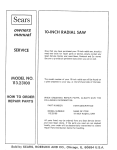
Sears
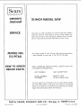
owners
manual
MODEL NO.
113.19760
Serial
Number
Model and serial
number may be found
at the front of the base.
You
model
should
record
and serial
CRRFTSMRNo
both
number
in a safe place for
future use.
IO-INCH
RADIAL
CAUTION:
SAW
Read GENERAL
and ADDITIONAL
SAFETY
• assembly
INSTRUCTIONS
• operating
carefully
Sold
Part No. 6.'4722
• repair
by SEARS,
ROEBUCK
AND
parts
CO.,
Chicago,
IL. 60684
U.S.A.
Printed in U.S.A.
FULL ONE YEAR WARRANTY
If within
one year from
workmanship,
Sears will
Warranty
service
United States.
This warranty
state.
ON CRAFTSMAN
the date of purchase, this Craftsman
repair it, free of charge.
is available
gives you
by simply
specific
contacting
legal rights,
Radial
the nearest
and you
RADIAL
Saw fails
SAWS
due to a defect
Sears store or Service
may also have other
rights
Center
which
in material
throughout
vary from
or
the
state to
SEARS, ROEBUCK AND CO.
BSC 41-3
SEARS TOWER
CHICAGO, IL 60684
general
safety
instructions
1. KNOW YOUR POWER TOOL
for power
13. SECURE WORK
Read
the
owner's
manual
carefully.
Learn
its
application
and limitations
as well as the specific
potential
hazards peculiar to this tool.
2. GROUND
ALL TOOLS
in
working
alignment.
and
in
proper
adjustment
and
KEEP
WORK
Cluttered
AREA
areas
must not
and
be slippery
6. AVOID
invite
due to wax
DANGEROUS
should
9.
DON'T
FORCE
USE
RIGHT
accidents.
Floor
a safe distance
from
SAFETY
Wear Safety
best and
lubricating
for
changing
ACCIDENTAL
sure switch
safest
and
accessories
such
as
STARTING
is in "OFF"
18. USE RECOMMENDED
position
before
switches,
Serious
cutting
plugging
by
removing
20.
CHECK
Before
and safer at the rate for which
TOOL
or attachment
to do a job
it was not
GOGGLES
(Head
comply
with
all times.
Also,
use face or dust
operation
is dusty, and ear protectors
during extended
periods of operation.
for
recommended
that accompany
accessories may
ON TOOL
or if the
materials above or near the tool such that
to stand on the tool to reach them.
DAMAGED
further
PARTS
use of the tool,
a guard or other
part that
is damaged should be carefully
checked to ensure that it
will operate properly
and perform
its intended
function.
Check
for alignment
of moving
parts,
breakage
parts,
conditions
goggles (must
ACCESSORIES
manual
injury could occur if the tool is tipped
tool is accidentally
contacted.
Do not store
it is necessary
or
owner's
19. NEVER STAND
KID-PROOF
master
the
accessories.
Follow
the instructions
the accessories.
The use of improper
cause hazards.
work
Do not wear- loose clothing,
gloves, neckties or jewelry
(rings,
wrist
watches)
to get caught
in moving
parts.
Nonslip
footwear
is recommended.
Wear protective
hair covering
to contain
long hair. Roll long sleeves
above the el bow.
USE
Make
in.
or sawdust.
11. WEAR PROPER APPAREL
12.
17. AVOID
for
TOOLS
servicing;
when
bits, cutters, etc.
Consult
TOOL
Don't force tool
designed for
TOOLS WITH CARE
16. DISCONNECT
ENVIRONMENT
be kept
It will do the job better
_t was designed.
10.
at all times.
Keep
tools
sharp
and clean
performance.
Follow
instructions
changing accessories.
AWAY
8. MAKE WORKSHOP
- with
padlocks,
starter keys.
and balance
CLEAN
benches
7. KEEP CHILDREN
footing
MAINTAIN
before
blades,
Don't
use power tools
in damp or wet locations
or
expose them
to rain. Keep work area well lighted.
Provide adequate surrounding
work space.
All visitors
area.
15.
KEYS
Form habit of checking to see that keys and adjusting
wrenches
are removed
from tool before turning
it on.
OVERREACH
Keep proper
IN PLACE
order,
4. REMOVE ADJUSTING
AND WRENCHES
5.
Use clamps or a vise to hold work when practical.
It's
safer than using your hand, frees both hands to operate
tool.
14. DON'T
This tool
i_ equipped
with an approved
3-conductor
cord and a 3-prong
grounding
type plug to fit the
proper grounding
type receptacle.
The green conductor
in the cord is the grounding
wire. Never connect the
green wire to a live terminal.
3. KEEP GUARDS
tools
that
other part that
or replaced.
21. DIRECTION
Feed work
of rotation
of
may
'affect
is damaged
parts,
binding
mounting,
its
operation.
should
of moving
and
any
A
be properly
other
guard
or
repaired
OF FEED
into a blade or cutter against
of the blade or cutter only.
the direction
Protection)
ANSI
Z87.1 ) at
mask if cutting
(plugs or muffs)
22. NEVER LEAVE
UNATTENDED
Turn power off.
complete
stop.
TOOL
Don't
RUNNING
leave
tool
until
it comes
to a
additional
safety instructions
--A large proportion
of saw accidents is caused by use
of the wrong type blade, dull, badly set, improperly
sharpened cutting
tools, by gum or resin adhering
to
cutting
tools,
and
by sawblade
misatignment
out-of-parallel
with
the fence. Such conditions
can
cause the material
to stick,
jam (stall the saw) or
"KICKBACK"
at the operator.
NEVER
ATTEMPT
TO FREE A STALLED
SAW BLADE
WITHOUT
FIRST
TURNING
THE
SAW
"OFF".
If the
CAUTION:
Always
disconnect
the power
cord before
removing the guard, changing the cutting tool, changing the
set-up or making
adjustments.
Shut off motor before
performing layout work on the saw table.
WARNING:
DO NOT CONNECT
POWER
CORD
THE
FOLLOWING
STEPS
HAVE
SATISFACTORI
LY COMPLETED:
UNTIL
BEEN
I.
Assembly
II.
Examination
and operating
familiarity
with
ON-OFF
switch,
elevation
control,
yoke index
and lock bevel
index
and lock, carriage
lock,
guard
clamp screw,
spreader and antikickback
device, and miter index and
lock.
III.
and alignment.
Review and understanding
of all Safety
Operating Procedures thru-out
manual.
Instructions
for radial saws
sawblade
is stalled
or jammed,
shut saw "'OFF",
remove workpiece,
and check sawblade squareness to
table surface and to the fence, and check for heel.
Adjust
and
INSTALLATION
1.
2.
Set carriage
Bolt
the
lock
saw to
slide during
before
the
normal
moving
floor
to
slip,
walk,
-- Do not leave a long board unsupported
so the spring
of the board causes it to shift on the table. Provide
or
operation.
3.
Mount
the saw so the table is approximately
the floor.
4.
Mount the saw so the arm slopes slightly
downward
the rear so the carriage
will not roll forward
due
39"
proper support
for the workpiece,
based on its size
and the type of operation
to be performed.
Hold the
work firmly against the fence.
above
to
to
- Never use a length stop on the free end or edge of the
workpiece
whether
crosscutting
or ripping.
Never
gravity.
MINIMIZE
Most
ACCIDENT
accidents
are
setup and operating
hang onto or touch the free end of workpiece
when
crosscutting,
or a free piece that is cut off while
power is "ON"
and/or
the saw blade is rotating.
In
short,
the
cut-off
piece
in
any
"thru-sawing"
operation
must
never be confined
it must
be
allowed to move laterally.
POTENTIAL
caused
by
FAILURE
TO
FOLLOW
instructions:
(A) GENERAL
-Avoid
could
awkward
hand positions,
where a sudden slip
cause a hand to move into a sawblade or other
-- Make sure your fingers do not contact
the terminals
when installing
or removing
the plug to or from a live
cutting
tool.
Never reach in back of or around the
cutting
tool
with
either
hand to hold
down
the
workpiece,
or for any other reason; DO NOT place
fingers or hands in the path of the sawblade.
- Never_ saw,
dado,
mold,
or rabbet
power source.
- Never climb on the
unless the proper
READ
1,
AND SAFETY
UNDERSTAND
WEXn
_OGGLES.
OWNER'S
YOUR
OWN
SAFETY
INJURY
MANUAL
BEFORESTICKOPERATING
4. USE "_JSH
FOR NARAOWMACHINE
WORK
3.
NOWTO
AVO_O
"KICKBACKS
'
2. KNOW
KEEPHANDS
OUT
OF PATH
OF SAWBLAOE
S.
TO STOP REFOREADJUSTING
S. ALLOW
NEVER TOOL
REACHAROUNO
THE SAWSLAOE
TO Avoid I_URY RETURNCARmAG_ TO THE FULL _AR
WARNING:
pOSITION
AFTER
EACH
CROSSCUT
TYPE
O €
DO ;
NOT
FEED
! MATEm*L
'i
INTO
CUTTING
[
i
.
I_OOL _ ROM
OPERATION.
I
THiS
I:NO
If any part of this radial saw is missing or should
break,
bend or fail in any way, or any electrical
component
fai! to perform
properly,
shut off power
switch,
remove cord from power supply and replace
damaged, missing and/or failed parts before resuming
operation.
- Never turn your saw "ON"
before clearing the table
or work surface of all objects (tools, scraps of wood,
etc.) except
the workpiece
and related
feed or
support devices for the operation
planned.
-
- IF YOUR
SAW MAKES
AN UNFAMILIAR
NOISE
OR
IF
IT VIBRATES
EXCESSIVELY
CEASE
OPERATING
IMMEDIATELY
UNTIL
THE
SOURCE
HAS
BEEN
LOCATED
AND
THE
PROBLEM
CORRECTED.
-WARNING:
DO
NOT
ALLOW
FAMILIARITY
workpiece
during the operation.
Never
crosscut
position.
Never make a miter
arm in the 90 ° crosscut position.
yoke,
and bevel
work
on
"RIP"
in the
cut with the
- Never lower a revolving
cutting tool into the table or
a workpiece
without
first locking the Carriage Lock
Knob. Release the knob only after grasping the Yoke
Handle.
Otherwise
the cutting
tool
may grab the
-Before
starting
work,
verify
that no play exists
between
the column
& column
support,
or in the
arm,
DO NOT perform
layout, assembly, or setup
the table while the cutting tool is rotating.
-Never
perform
any operation
"FREE
HAND".
This
term means feeding the sawblade into the workpiece
or feeding the workpiece
into the sawblade
or other
cutting
tool without
using the fence or some other
device
which
prevents
rotation
or twisting
of the
(GAINED
FROM
FREQUENT
USE OF YOUR
SAW)
TO BECOME
COMMONPLACE.
ALWAYS
REMEMBER
THAT
A CARELESS
FRACTION
OF
A SECOND
IS SUFFICIENT
TO INFLICT
SEVERE
INJURY.
carriage, and that
are tight.
near the saw when
-Do
not use any blade or other cutting
tool marked
for an operating
speed lower than 3450 RPM. Never
use a cutting tool larger in diameter than the diameter
for which the saw was designed.
For greatest safety
and efficiency
when
ripping,
use the
maximum
diameter
blade for which
the saw is designed,
since
under these conditions
the spreader
is nearest the
blade.
DANGER
FOR
saw, or climb
power
is "ON".
Never leave the saw with
power
"ON",
or before
the cutting
tool
has come to a
complete
stop. Lock the motor switch and put away
the key when leaving the saw.
guard is installed and set up as instructed.
NOTE
THE
FOLLOWING
DANGER
LABELS
WHICH APPEAR
ON THE FRONT
OF THE YOKE
AND GUARD:
r
DANGER:
DO NOT cycle the motor switch
"ON'"
rapidly, as this might cause the sawblade
In the event this should ever occur, allow
the saw blade to come to a complete
stop
and
re-tighten the arbor nut normally, not excessively.
the saw.
if it tends
as indicated.
--CAUTION:
and "OFF"
to loosen.
workpiece
locks/clamps
-The
3
and be propelled
sawblade,
dado,
toward
or other
you.
cutting
tool
must
be
additional
instructions
safety
removed
from
the saw
arbor
before
using the
accessory shaft (rear end of the saw motor).
NEVER
operate the saw with cutting tools (including
sanding
accessories)
installed on both ends of the saw arbor.
(B) RIPPING
1.
Never apply
the feed force to the section
of the
workpiece
that will become the cut-off
(free) piece.
Feed force when ripping
must always be applied
between
the saw blade and the fence ...
use a
"PUSH
work.
2.
3.
4.
STICK"
(see pg. 25)
for
Whenever
possible,
use the in-rip
provides
minimum
obstruction
for
or push stick as appropriate.
narrow
or short
position
- this
feeding by hand
Do not release the workpiece
before operation
is
complete
- push the workpiece
all the way past the
rear (outfeed
or exit) of the sawblade.
Make sure by trial before starting
the cut that the
antikickback
pawls will stop a kickback
once it has
started.
Keep points of pawls SHARP!
5.
Use a
inches)
6.
CAUTION:
antikickback
7.
A "KICKBACK"
occurs during a rip-type operation
when a part or all of the workpiece
is thrown
back
violently
toward
the operator.
It can occur when
the workpiece
closes in on the rear (outfeed side) of
the sawblade
(pinching),
binds between
the fence
and the sawblade
(heel),
or is grabbed
by the
sawblade
teeth
(wrong-way
feed) at the outfeed
side.
"PINCHING"
is generally
avoided
by
utilization
of the spreader, and a sharp sawblade of
the correct
type
for
the workpiece
being cut.
"HEEL"
can
be avoided
by
maintaining
the
sawblade exactly
parallel to the fence. Grabbing by
the sawblade
teeth can be caused by heel or by
feeding from the wrong direction
(see "DANGER"
warning
on guard)
it
can
be avoided
by
maintaining
parallelism
of sawblade
to
fence,
feeding
into
the sawblade
from
the nose of the
guard only,
and by positioning
the spreader
and
antikickback
property,
and keeping the workpiece
down on the table and against the fence.
8.
9.
push stick
when ripping
short
(under
12
or narrow
(under 6 inches wide) workpieces.
Never
reposition
with power "ON".
the
Position
the nose of the guard
workpiece,
and position/adjust
and spreader devices as instructed.
NEVER
stacking
cut more
workpieces
than one
vertically.
Guard
or
to just clear the
the antikickback
piece
at
a time
by
10. NEVER
feed a workpiece
thru the saw with another
piece (butting
second piece against trailing
edge of
piece being cut), even if of the same thickness.
Feed
each workpiece
individually
thru the sawblade, and
completely
beyong the sawblade, before ripping the
next workpiece.
Use push stick if the rip cut is less
than 6" wide.
11. DO NOT
pull
the workpiece
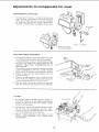
12. Plastic and composition
(like hardboard)materials
may be cut on your saw. However,
since these are
usually
quite
hard and slippery,
the antikickback
pawls may not stop a kickback.
rip with the finished
side down (next to
and be especially
attentive
to following
saws
proper set-up and cutting
or permit
anyone
else
potential
kickback.
procedures.
Do not stand,
to stand,
in line with
a
13. When sawing 1/4"
or thinner
materials,
follow
all
normal
ripping
procedures
except set sawblade into
table top at least 1/8".
DO NOT let go of or stop
feeding the workpiece
between
the blade and fence
until
you
have pushed
it completely
past the
antikickback
pawls. Otherwise
the workpiece
could
get into the back of the sawblade and be thrown
violently
from the saw in the direction
opposite
to
the feed direction.
This is the same action
that
would
occur
if the instructions
of the DANGER
warning
on the guard is aborted.
Do not stand, or
permit
anyone else to stand, in line with the path of
a workpiece
that may be thrown
from the saw in
this manner.
14. Position the saw so neither you,
observer
is forced
to stand
sawblade.
a helper, or a casual
in line
with
the
15. Use extra care when ripping wood that has a twisted
grain or is twisted
or bowed - it may rock on the
table and/or pinch the sawblade.
(C) CROSSCUTTING
1.
ALWAYS
RETURN
THE
CARRIAGE
TO THE
FULL
REARWARD
POSITION
AT CONCLUSION
OF EACH CROSSCUT
TYPE OPERATION.
Never
remove your hand from the Yoke Handle unless the
carriage
is in this position.
Otherwise
the cutting
tool
may
climb
up on the workpiece
and be
propelled
toward
you.
2.
Place
guard
antikickback
or workpiece,
3.
NEVER
gang crosscut
- lining
up more than one
workpiece
in front of the fence - stacked vertically,
in horizontal
position
and adjust
pawls to just clear the top of the fence
whichever
is higher.
or horizontally
outward
on the table - and then
pulling
saw thru:
the blade could pick up one or
more pieces and cause a binding or loss of control
and possible injury.
4.
Do not position
the Arm so the operation
you are
performing
permits
the cutting
tool
to extend
beyond the edges of the Table.
(D) ACCESSORIES
1.
Use only
33.
2.
Never operate this saw when equipped
with a dado
head or molding
head unless the molding
head
guard
is installed
-- see listing
of recommended
accessories.
The only exception
is when "top-side"
dadoing or molding,
when the sawblade guard must
be used. See detailed
instructions
that accompany
3.
thru the sawblade
-position
your body at the nose (in-feed)
side of
the guard: start and complete
the cut from that
same side. This will require added table support
for long pieces.
Therefore,
the table)
for radial
recommended
the dado
guard.
head,
The
of
use
accessories
molding
abrasive
or
head,
cut-off
as listed
and
on page
molding
wheels,
or
head
wire
wheels, can be dangerous and is not recommended.
(Abrasive
or cut-off
wheels are used to saw many
different
materials
including
metals,
stone,
and
glass.)
4.
Drill
Chuck:
Do not install
or use any twist drill
larger than 1/2-inch
in dia., or longer than 7 inches
in length or extending
more than 6 inches beyond
the chuck jaws. Do not install or use any reduced
shank drill except of the spade type (1 inch dia. or
smaller).
"Use for drilling
WOOD
and PLASTIC
only."
WEAR
YOUR
The operation
of any power tool
can result in foreign
objects
being thrown
into the eyes, which
can result in
severe eye damage. Always
wear safety goggles complying
with
ANSI Z87.1 (shown on Package) before commencing
power tool operation.
Safety Goggles are available at Sears
retail or catalog stores.
electrical
connections
POWER SUPPLY
1.
housing at one end and to the
attachment
plug at the other end.
Motor Specifications
The A-C motor
used in this
non-reversible
type having the
This plug requires
outlet as shown.
saw is a capacitor-start
following
specifications:
Voltage
.................................
Amperes
................................
Hertz (cycles)
.............................
...
MANNER.
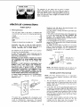
Use an adapter as shown
the grounding
lug to known ground.
Single
3450
Clockwise
It it recommended
replace
THREE
CAUTION:
Your saw is wired for 120V
operation.
Connect to a 120V, 15-Amp. branch circuit and use a
15-Amp.
time-delay
fuse or circuit
breaker.
3-PRONG
PROPERLY
GROUNDED
OUTLET
J
GROUNDING
PLUG
that
the "nNO prong
prong outlet.
you
grounded
and always
have a qualified
outlet
with
GROUNDING
type
connect
electrician
a properly
grounded
3-PRONG
PLUG
.__ f
LUG
SURE
t._s _s
..__- mAKE
CONNECTED
tOA
KNOWN
GROUND
_P O.O
RECEPTACLE
NOTE: The adapter illustrated is for use only if you
already have a properly grounded 2-prong receptacle.
MOTOR
SAFETY
PROTECTION
NOTE:
This motor should be blown out, or "vacuumed",
frequently
to prevent
sawdust
interference
with normal
motor ventilation.
1.
This tool should be connected
to
branch circuit
with a 15 amp time
breaker.
Failure to use the proper
damage to the motor.
a 120 volt, 15 amp
delay fuse or circuit
size fuse can result
in
2.
If the motor fails to start, turn the power switch to the
off position
immediately.
UNPLUG
THE TOOL. Check
the saw blade to insure that it turns freely and that its
teeth are not wedged into the table top. After the blade
has been freed, try to start the motor again. If, at this
point, the motor
still fails to start, refer to the "Motor
Trouble-Shooting
Chart."
3.
If the motor should suddenly
stall while cutting wood,
the power
switch
should
be turned
off,
the tool
unpluged
and the blade freed
from
the wood.
The
motor may now be restarted and the cut finished.
PRONG
This power tool is equipped
with
a 3-conductor
cord
and grounding
type plug which has a grounding
prong,
Listed
by
Underwriters'
Laboratories.
The ground
conductor
has a green jacket and is attached to the tool
in the
An adapter as shown below is available for connecting
plugs to 2-prong
receptacles.
The green grounding
lug
extending
from
the adapter
must be connected
to a
permanent
ground
such as to a properly
grounded
outlet box.
This machine must be grounded while in use to protect
the operator from electric shock.
IF YOU ARE NOT SURE THAT YOUR OUTLET IS
PROPERLY GROUNDED, HAVE IT CHECKED BY A
QUALI FlED ELECTRICIAN.
WARNING:
DO NOT PERMIT FINGERS TO TOUCH
THE TERMINALS
OF PLUGS WHEN INSTALLING
OR REMOVING
THE PLUG TO OR FROM THE
OUTLET.
WARNING:
IF NOT PROPERLY GROUNDED
THIS
POWER
TOOL
CAN INCUR THE POTENTIAL
HAZARD
OF
ELECTRICAL
SHOCK.
PARTICULARLY
WHEN
USED
IN
DAMP
LOCATIONS IN PROXIMITY
TO PLUMBING. IF AN
ELECTRICAL
SHOCK OCCURS THERE IS THE
POTENTIAL OF A SECONDARY HAZARD SUCH AS
YOUR HANDS CONTACTING THE SAWBLADE.
IF POWER CORD IS WORN OR CUT, OR DAMAGED
IN
ANY
WAY,
HAVE
IT
REPLACED
IMMEDIATELY.
3-conductor
prong
If the outlet you are planning to use for this power tool
is of the two
prong
type
DO NOT
REMOVE
OR
ALTER
THE
GROUNDING
PRONG
IN ANY
120
11.5
60
Phase
................................
RPM ..................................
Rotation
as viewed from saw blade end
a mating
ground
electrical
4.
Frequent
if motor
connections
differently
from
recommendations.
Overloading
can
occur if you feed to rapidly or if your saw is misaligned
so that the blade heels. Do not
use a fuse of greater
capacity without
consulting
a qualified
electrician.
5,
6.
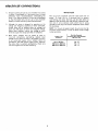
WIRE SIZES
opening of fuses or circuit
breakers may result
is overloaded,
or if the motor circuit
is fused
Although
the motor
is designed for operation
on the
voltage
and frequency
specified
on motor
nameplate,
normal
loads will be handled
safely on voltages
not
more than 10% above or below the nameplate
voltage.
Heavy
loads, however,
require
that voltage
at motor
terminals
equals the voltage specified on nameplate.
Most
motor
troubles
may
be traced
to loose or
incorrect
connections,
overloading,
reduced
input
voltage (such as small size wires in the supply circuit)
or
to an overly-long
supply
circuit.
Always
check
the
connections,
the load and the supply circuit,
whenever
the motor
fails to perform
satisfactorily.
Check wire
sizes and lengths
with
the table
following.
The use of
power.
To
any extension
keep
this to
over-heating
and motor
determine
the minimum
cord will cause some loss of
a minimum
and to prevent
burn-out,
use the
wire size (A.W.G.)
table below to
extension
cord.
Use only
3 wire
extension
cords which
have 3 prong
grounding
type plugs and 3-pole
receptacles which accept
the tools plug.
NOTE:
For circuits
of greater length, the wire size must be
increased
proportionately
in order to deliver ample voltage
to the saw motor.
Length of the
Conductor
Up to 100 feet
100 feet to 200 feet
200 feet to 400 feet
Wire Size Required
(American
Wire Gauge Number)
120 Volt Lines
No. 12
No. 8
No. 6
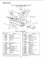
LOCATIONS
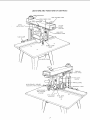
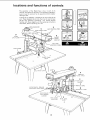
MITER
AND
FUNCTIONS
INDICATOR
ARM
BEVEL INDEX
RiP SCALE
OF CONTROLS
CONTROL
LEVER
LEVER
INDICATOR
SWIVEL
LATCH LEVER
ON-OFF
SWITCH
WITH KEY
ARM LOCK
JSTING
WHEEL
TABLE
CLAMP
\
GUARD
CLAMP
SCREW
ELEVATION
CRANK
\
CARRIAGE
LOCK
KNOB
'OKE LOCK
HANDLE
MANUAL
ANTIKICKBACK,
SPREADER
ADJUSTING
WING
SCREW
BRAKE
SHAFT
ANTIKICKBACK
AND SPREADER
ASSEMBLY
BEVEL INDEX
INDICATOR
7
BEVEL LOCK
LEVER
CONTENTS
Guarantee
General
....................................
Safety
2
Instructions
for
Power
Tools
AdditionaJ
Electrical
Safety
Instructions
for Radial
Connections
..........................
Assembly
and
Alignment
Unpacking
and
Alignment
Procedure
Saws
2
.......
3
5
........................
Preassembly
assembly
.........
8
.....................
8
.........................
11
Location
and Functions
of Controls
...............
Basic Saw Operations
..........................
Adjustments
to Compensate
for Wear ..............
Trouble-Shooting
............................
Maintenance
and Lubrication
....................
Recommended
Accessories
......................
19
22
27
30
33
33
Repair
34
Parts
.................................
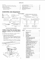
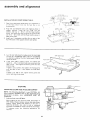
and alignment
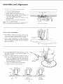
TOOLS NEEDED
FRAMING
CHECKING
INSIDE
REAR
EDGE
(FENCE,
7/16-inch
wrench
(medium)
Screwdriver
(small)
MUST
OF
BE TRUE
CHECKING
ACCURACY
OUTSIDE
OF
FRONT
SPACER
BOARDS
Screwdriver
SQUARE
ACCURACY
OF SQUARE
OF
TABLE
AND
BACK
)
REMOVED)
FENCE
1!2-inch
TABLE
/
wrench
TT,_'
.L ,/,_
T
T
J'J L : _. _'
;, t
h
ALO_°
THI?
AND
WARNING:
DO NOT
CONNECT
A SOURCE
UNPLUGGED
THE SAW.
OF POWER.
WHENEVER
POWER
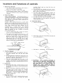
Your Craftsman
10-inch
Radial Saw is shipped
one carton. Steel Legs is an optional
accessory.
Unpacking
and Checking
CORD
TO
complete
in
Contents
Separate all "loose"
parts from packaging materials
and
check each item with "Table
of Loose Parts" to make
sure all items are accounted
packing material.
for,
before
discarding
any
If any parts are missing, do not attempt
to assemble
radial saw, plug in the power cord, or turn the switch
4
BE
OVERLAP
SQUARE
HERE ,VHEN
IS FLIPPED
OVER
DOTTED
on until
correctly.
THIS
CORD
MUST
REMAIN
YOU
ARE
WORKING
ON
Key No.
(Fig. 1)
1
2
3
4
5
6
7
NO
SHOULD
IN
PREASSEMBLY
THE
ON
EDGE
,
UttJ
SHOULD
BENOGAPOR
J, hJ
Pencil
UNPACKING
3
TABL_
LINE
_'r'l'_'l'_'_
r,.i'
"_'," 't ,t,52, square
," ? 7.L
_
Framing
Pliers
7
LIGHT
__
I]:
2
DRAW
wrench
!.r: RZ'_'_
1.
(_
I
oE \
DR A¢,'
--/_----
gi 16-inch
OF
SQUARE
GAP
OR
OVERLAP
SQUARE
POSITION
the missing
IN
HERC WHEN
IS
FLIPPED
DOTTED
OVER
POSITION
parts are obtained
and are installed
Table of Loose Parts
Qty.
Basic Saw assembly ......................
Rear table .............................
1
1
Rip fence .............................
Front table ............................
1
1
Channel, Table Mtg ......................
"Owner's Manual" . .....................
2
1
Table Spacer ...........................
Loose Parts Carton Part No. 62724
(containing the following items):
- Hex "L" Wrench, 1/8"
. ................
- Switch Key ..........................
- Rip-Scale Indicator ....................
- Twin Nut (for attaching rip-scale indicator)
- Machine screw, pan-hd., 1/4-20 x 1" . ......
- Washer, steel (Flat), 17/64 x 5/8 x 1/32"
...
- Machine screw, pan-hd., 6-32 x 7/16" . .....
- Lockwasher, 5/16 .....................
- Washer, Flat, 11/32 x 7/8 x 1/16"
. .......
-Nut-'T"
. .........................
1
1
2
1
1
4
5
2
4
4
1
-
1
1
4
4
2
Set Screw, Cup.Pt. 1/4-20 x 1 ............
Screw Pan Head, 1/4-20 x 1-3/4 ..........
Nut Hex 1/4-20 .......................
Lockwasher 1/4 ......................
Nut Lock 5/16-18 .....................
- Bolt Sq. Hd. 5/16-18 x 3/4 ..............
- Washer 21/64 x 9/16 x 1/16 .............
- Nut, Hex 5116-18 .....................
4
2
4
Loose Parts Bag Part No. 63723
(containing the following items):
- Hex "L" Wrench, 1/4 ..................
- Hex "L" Wrench, 3/16 .................
- Elevation crank assembly ...............
- Arbor Wrench ........................
- Table Clamp .........................
- Shaft Wrench ........................
1
1
1
1
2
1
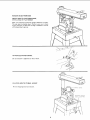
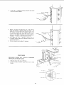
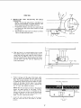
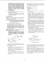
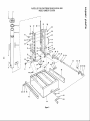
REMOVE
MOUNT
STEEL
SKIDS
FROM
BASE
SAW TO CRAFTSMAN
BASE,
LEGS, OR FLAT BENCH
Make sure Elevation Crank has proper clearance to rotate.
The saw must be bolted down. Position
your saw to slope
slightly
rearward, so when the carriage is installed it will not
rol! forward
due to gravity.
/
ATTACH
ELEVATION
Be sure setscrew
ELEVATE
Remove
ARM
shipping
CRANK.
is tightened
on flat of shaft.
TO ITS MAX.
block
HEIGHT.
and discard.
NG
BLOCK
EL[VATION
(TURN
9
CRANK
CLOCKWISE)
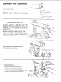
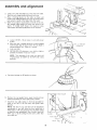
assembly
and alignment
BE positive
switch
is "OFF"
thru-out
entire procedure.
and
power
cord
unplugged
WARN INS
TAG
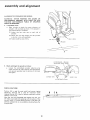
REMOVE
CARRIAGE
AND
TAG.
discarding.
Read
STOP
and
SCREW,
understand
LOCK ARM BEFORE
HOLDING
HANDS,
CARRIAGE
CARRIAGE
CAREFULLY
ONTO THE
LOCKWASHER
warning
tag
before
PROCEEDING.
ASSEMBLY
WITH
BOTH
START
AND
SLIDE
THE
TRACKS.
The assembly
must be
held parallel
with
the arm so that all four bearings slide
smoothly
onto the arm, preventing
any excessive strain on
bearings and track.
WARNING:
PREVENT
Check
REINSTALL
CARRIAGE
for
"Adjusting
Compensate
REMOVE
Use
of
looseness
CARRIAGE
STOP SCREW
FROM ROLLING
OFF ARM.
of
carriage
Carriage
Bearings"
for Wear" Section.
SHIPPING
pliers
may
SCREWS
be
AND
bearings.
in
Refer
"Adjustments
TO
to
to
DISCARD.
__
__
_-
REMOVE
SAW
UNDERSIDE OF MOTOR
necessary.
Tll "_11 III I
SHOWING
LOCATION
OF TWO
BLADE.
1.
Tighten
carriage
2.
Loosen
guard
lock knob.
3.
Motor
shaft has left hand threads.
Hold
and rotate arbor wrench down (clockwise).
4.
Remove shaft nut, outer collar, saw blade, inner
and motor spacer. Set aside and out of the way.
clamp
screw,
remove
guard.
shaft
PULL DOWN
TO LOOSEN
wrench
collar
BLADE
ROTATIO
lo
N
ALIGNMENT
PROCEDURE
IMPORTANT:
SQUARE
HDo
SCREW
s/16-18 x 314
IN ORDER TO OBTAIN
MAXIMUM
CUTTING
ACCURACY,
THE FOLLOWING
SIX STEPS
MUST
BE
CAREFULLY
FOLLOWED.
BECOME
THOROUGHLY
FAMILIAR
WITH
THESE STEPS SO THAT YOU CAN ALWAYS
MAINTAIN
YOUR
SAW
IN
PROPER
ALIGNMENT.
THE ACCURACY
OF EACH
ADJUSTMENT
IS ALWAYS
DEPENDENT
UPON THE ACCURACY
OF THE PRECEDING
ADJUSTMENT.
Afte_
following
the
6 step
assembly
procedure
and the Basic Saw operation
Trouble
Shooting
section
if any difficulty
when performing
any sawing operation.
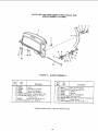
TABLE
MOUNTING
SUPPORT
TABLE
MOUNT!
NG
SUPPORTCHANNEL
CHANNEL
\
SCREWS
HERE
LOCKWASHER
FLAT
and
alignment
section
refer to
is experienced
/
WASHER
BASE
STEP ONE
NOTE:
The following
adjustment,
performed
properly,
result in the work table being parallel to the arm.
ATTACHING
AND
SUPPORT
CHANNELS.
1.
LEVELING
TABLE
3.
MOUNT
RAILS
THESE
MOUNTING
channels
to
Release bevel lock lever, move
and rotate the motor to position
down. Lock bevel lock.
bevel index pin to left
saw blade, end of shaft
Unlock
lever
and
hold
arm
control
in
index
LOCK
FRONT
USING
HOLES
Attach
table
mounting
support
channels
with
four
s_tuare head 5/1 6-18 x 3/4 screws, Iockwashers
and flat
washers and nuts. POSITION
SCREWS IN CENTER
OF
CHANNEL
SLOTS,
finger tight
to permit
"stip" against the base when leveling.
2.
_
will
UNLOCK
_'_
INDEX
RELEASE
POSITION'
release
position
as shown.
Position
arm
against
left
stop
(approximately
50 ° miter).
Loosen carriage lock knob
and position carriage directly
over left hand channel.
NOTE:
For safety reasons
standard,
stops have been
rotation
of the radial arm.
SI de the
4.
arbor
wrench
in accordance
provided
to
handle
with the UL
prevent
360 °
between
end
of
motor
shaft and mounting
channel to act as a feeler gauge.
C_efully
lower the motor
with elevation
crank until
the end of shaft is just touching
the arbor wrench. The
wrench
should slide back and forth
with only slight
resistance. Tighten screw "A".
NOTE:
Do not change this elevation
setting
left and right hand table support
channels
adjusted.
Move
arm and carriage
to
support in the same manner.
6.
Move arm and carriage to right hand support
channel
arid level in the same manner you adjusted the left hand
support channel.
7.
Recheck
both
support
channels
t ghtening
screws did not affect
adjustment.
8.
Elevate
t_rovide
in
to
the
"'B"
ARBOR
SCREW
5.
saw and place motor
clearance for installation
screw
until both
have been
and
WRENCH
"A "_
tighten
make sure that
accuracy
of the
vertical
position
to
of front (work)
table.
I
_
_
I
'
//_
_
SCREW "B"
SCREW
11
"A"
TABLE MO_UNTING
SUPPORT
CHANNEL
assembly
and alignment
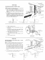
FRONT
IN
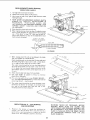
INSTALLATION
1.
2.
3.
OF FRONT
(WORK)
TABLE.
T-NUT
Place front
table board upside down on a workbench
or
on the floor.
Drive T-nut
into the hole that is not
counterbored.
.i-
_
Install
one
1/4 Iockwasher
(4) screws
and
in the support
Hex Nut
channels
HOLE
FOR TABLE
UPSIDE
DOWN
POSITION)
HOLD
DO'NN
SCREWS
(TYPICAL)
/
oL
o
BOTTOM
T-NUT
\
;it
/
PAN
HD.
,
OF
t
1/4-20 × _-3/4"
Align
the counterbored
holes with
matching
holes in
support
channels.
Install
the five
17/64
inch flat
washers, and four Y_- 20 x 1 inch Pan-Head machine
screws. Just barely start the cup point set screw and the
one (1) ¼ - 20 x 1-3/4 inch Pan Head machine screw in
table center holes.
four
F
fABLE
f
1/4-20 x I"
SCREW
PAN
FLAT
WASHER
.._
HD.
CJP
POINT
SCREW
.
FRONT
TABLE
_
on each of the
and tighten.
HEX
NUT
LOCKWASHER
4.
Lay
the rear table
board
on edge across the front
table
to serve as a straightedge.
Sight under this straightedge
to determine
whether
the front
table board is high or
low at its center.
5.
REAR TAiLE
HOLD
If table is low at center, first tighten
the leveling
until
the table is level - then tighten
the hold
screw.
If table is not high or low, tighten
center hold down screw snug.
_
leveling
screw
down
screw and
FRONT
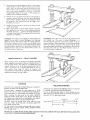
STEP TWO
ADJUSTING
COLUMN
TUBE
IN COLUMN
SUPPORT
NOTE:
The following
adjustment
is very CRITICAL.
All
future
alignment
procedures
rely on this adjustment
being
performed
correctly.
ALL
LOOSENESS
MUST
BE
REMOVED.
1.
DOWN
If the front
table is high at center,
first tighten
the
center
(¼ - 20 x 1-3/4 inch) hold down screw until the
table is level - then tighten the leveling screw until this
screw is snug.
Index
and lock
While
other
holding
the arm with
one hand, hold fingers of
hand as shown, between column tube and column
support.
opposing
movement
arm at 0 ° Miter.
Apply
gentle
side pressure
to the arm in
directions.
Any
side to side or rotational
(indicated
If
looseness
required.
exists
by arrow)
the
can be felt with
following
adjustments
finger.
are
12
TABLE
SIDE
TABLE
\
BOARD
_,,_
->
2.
3.
4.
Loosen (2) ¼ - 20 Gib set screws
rear of the column support.
Elevate,
and then lower the Arm:
(a) if the column
binds and elevation
is difficult
loosen two 5/1618
plated nuts on front
side of the column
support
until
you
achieve
smooth
but firm
elevation.
(b) If the
column
moves side-to-side
within
the column support,
tighten
the two 5/16 - 18 plated nuts until movement
disappears -- elevation
should be smooth and firm.
Now
tighten
the
(2)
noticeable
rotational
and Column Support.
5.
on the left side at the
Recheck
elevation
¼ -play
20 Gib
exists
and re-adjust
set screws
between
until
Column
OR,O.T
PLATED "
\
©
no
Tube
if necessary.
STEP THREE
SQUARING
TRAVELS
CROSS
CUT
TRAVEL
IN A STRAIGHT
LINE).
1.
Index but do not lock arm at 0 ° miter.
2.
Install saw blade
threads.
as shown.
Motor
shaft
(CARRIAGE
has left
hand
_:::_
_/
MOTOR
SAW
OUTER
o
END
OF
ARBOR
RESTING
ON
WRENCH
TABLE
SPACER
BLADE
COLLAR
SHAFT
NUT
INNER
MOIOR
13
COLLAR
assembly
and alignment
3.
Lower arm until saw blade
Lock the yoke clamp handle
4.
Place a framing
square
on the table
as shown
and
position
the blade and square until the leg of the square
just contacts a tooth of the blade. Mark this tooth.
5.
When the carriage is moved back and forth on the arm,
the marked
tooth
should just touch the square at all
points.
If marked
tooth
moves into square or away
from square the following
adjustments
are required:
(3) 3/8
16 set screws
in arm latch
table.
a.
Loosen
of arm.
b.
Move the arm in proper direction
to make marked
tooth
follow
edge of square when the saw blade is
moved along arm in a "cross cut" manner.
c.
Lock
d.
RETIGHTEN
(3) setscrews in arm latch
possible and recheck "cross cut" travel.
Set miter
BEVEL
indicator
squaring
of
set BOTH
TOOTH
at rear
HEX
as tight
as
as shown.
CLAMP
6,
Position
the rip (guide)
fence, spacer board and
table board behind the front table board as shown.
7.
Install the two table
them at the rear of
securely.
"L"
WRENCH
(SUPPLIED)
the cross cut travel will
of the 45 ° miter index
on 0 ° position
LOCK
LEVER
arm latch.
NOTE:
This
simultaneously
positions.
e.
-
just clears the front
and bevel lock lever.
rear
clamps in the holes provided
for
the saw base, and tighten
them
NOTE:
The life of your saw table will be lengthened
considerably
if you will cover the front
table with
a
fitted
piece of 1/4 inch plywood.
This should be tacked
in place for easy replacement.
Use of such a cover will
allow you to do all cutting
into the cover, rather than
your table top.
WASHER
REAR TAB
RIP FENCE
SPACER
FRONT
14
TABLE
STEP FOUR
SQUARING
SAW BLADE TO (WORK) TABLE
NOTE: If alignment
procedure
step one was not performed,
this adjustment
can not be accomplished.
1.
Place a framing
square on the table with the short leg
against the saw blade. Do not allow the square to rest
against a "set-out"
tooth; it must rest flat against the
blade side.
2.
RIP FENCE
N
If the saw blade is square with the table top (no visible
gap appears between the saw blade and square) and no
adjustment
is required.
Set bevel
indicator
to 0 °
reading.
If the square does not touch the saw blade as
shown (with square leg held firm against the table top),
perform
the following
adjustments
BEVEL INDICATOR
SQUARE
k
SQUARE
_
[
I
TABLE
L
I
WRONG
carriage
lock
WRONG
a.
Tighten
b.
Remove bevel scale by removing 5/16-18
Head Screw.
c.
Loosen the four socket head screws with
1/4" Hex
"L °' Wrench.
Rotate
motor
while
holding
square
firmly
against saw blade and table top.
knob.
d.
Slightly
tighten
• .. Now tighten
each of the four screws
each screw tight.
e.
Reinstall
reading.
scale
f.
Loosen
bevel
carriage
lock
RIGHI
and
adjust
x 1 Pan
5/16-18x
PAN HEAD SCREW
and recheck
indicator
on
0°
knob.
LOOSEN
THESE
FOUR SCREWS
STEP FIVE
SQUARING
BLADE
HEEL ADJUSTMENT.
TO
RIP
(GUIDE)
FENCE
-
LEFT HAND
CARRIAGE
COVER
BLADE
NOTE:
If alignment
procedure
steps two and four were not
performed,
this alignment
step cannot be accomplished.
Position
carriage
as shown
and tighten
carriage
lock
knob. Place a framing
square against the rip fence and
the saw blade, as shown.
The long leg of the square
must be held firmly against both the fence and the table
top, and the short leg must not touch any of the teeth
on the saw blade. Check at several points
of blade
rotation.
2.
If the square does not touch the blade at both
two points as shown, a heel condition
exists.
RIP FENCE
of the
FENCE
FENCE
FENCE
]
SQUARE
_
50LIARE
MOTOR
II "
_'_fc
MOTOR
i !'J___.- j
'VRONG
i
SQUARE
LI
15
WRONG
t:j Lo,o
assembly
3.
To
correct
and alignment
"heel"
condition
proceed
left hand carriage
as follows:
a.
Remove
b.
Loosen
the yoke
clamp
c.
Loosen
(slightly)
the two
d.
Rotate
the yoke assembly
until
saw blade and square is eliminated.
e.
Lock
yoke
clamp
hex-head screws,
handle
f.
Recheck
and install
g.
Loosen
for "heel"
carriage
lock
cover.
handle.
HEX HEAD SCREWS
hex-head
and
screws.
gap
between
retighten
carriage
the
the
two
cover.
knob.
NOTE:
This alignment
procedure
will simultaneously
both yoke indexing
positions
for blade in and out rip.
set
LEFT
SIDE OF
CARRIAGE
I
VERTICAL
1.
With
sawblade
rotate
check
2.
HEEL
I
I
I
ADJUSTMENT
in 90 ° cutoff
position,
elevate
saw and
motor to vertical position
(Blade Horizontal)
for heel. Make sure bevel lock lever is locked.
BEVEL
and
Position
square
perpendicular
to fence and between
blade and table, as shown lower arm. Do not allow the
square to rest against a "set-out"
tooth, it must rest flat
against the blade side.
LOCK
/_
LEVER
I
3,
4.
CLOCKW
If the saw blade is parallel with the table top (no visible
gap appears
between
the saw blade and square),
no
adjustment
is required.
COUNTER
CLOCKWISE
If there is a visible gap between saw blade and square, a
bevel heel condition
exists and adjustment
is required.
a.
To correct,
unlock
bevel lock lever, loosen the rear
motor
mount
3/8-16 nut until you can rotate Cam,
and then rotate
Cam as shown
until gap between
saw blade and square is eliminated.
b.
Tighten
c.
Reposition
nut and bevel
motor
lock
\
lever and recheck.
in crosscut
position.
FENCE
\
I
RIGHT
TABLE
WRONG
(TURN
WRONG
CAM
COUNTERCLOCKWISE)
16
(TURN
CAM
CLOCKWISE)
]
SCREW
STEP SiX
INSTALLING
INDICATORS.
1.
AND
ADJUSTING
RIP
SCALE
NOTE:
The rip scale and pointer
is intended
used for quick settings.
For greater accuracy,
direct measurement
between blade and fence.
Pre-assemble
not remove
a.
to be
take
RIP SCALE
INDICATOR
indicator
and twin nut, loosen but do
the two screws which attach left hand
carriage cover.
b.
Tilt carriage cover and install rip indicator
Tighten carriage attaching
screws.
as shown.
TWIN
NUT
1
d.
With the fence in its normal
position
(next to the
front table), loosen the yoke clamp handle, pull on
swivel latch pin knob and rotate the yoke as shown
to index the yoke 90 ° from the cross cut position.
This will locate the saw blade between
the motor
and the fence.
Lock
yoke clamp handle.
the
yoke
by
tightening
the
FENCE
FRONT
I
REAR TABLE
e.
Position
carriage until the edge of the blade, when
spun by hand, just touches the front
face of the
fence. The rip-scale indicator
(on the left hand side
of radial arm) should now read "'0" inches on upper
portion
of the blade "In-Rip"
scale. If not, loosen
screws and shift the indicator
until it is aligned with
the "O" mark, then tighten the screws.
RIP SCALE INDICATOR
\
NOTE: With the saw blade and fence in the position
shown,
the upper portion
of the blade "In-Rip"
scale is used.
If the fence
is re-located
at the
extreme
rear position,
the saw must be repositioned
for blade "Out-Rip"
and the lower portion
of the
blade "Out-Rip"
scale would be used.
Loosen the yoke clamp handle,
latch pin knob and return
the
position.
®
pull on the swivel
blade to the 90 °
@
\
\
YOKE PIVOT
LATCH
17
J
TABLE
assembly
ALIGNMENT
and alignment
OF SPREADER
WARNING:
NEVER
FOR
POSITION
ANTIKICKBACK
ASSEMBLY
POSITION
ANTIKICKBACK
PAWLS OR SPREADER.
2.
Install Blade
a.
RIPPING.
THE
GUARD
OR
WITH
POWER
ON; NOR
PAWLS
BY
GRASPING
Y
Guard.
Sight (visually)
to check
for proper
alignment
of
spreader with saw blade as shown.
If the spreader is
not aligned, adjust it as follows:
(1)
Loosen
two
hex
nuts,
one
on
each
side
of
spreader.
(2)
Rotate hex nuts with
is directly
in line with
(3) Tighten
fingers until
saw blade.
the
spreader
both hex nuts firmly.
WING
SCREW
\
ANTIKICKBACK,
SPREADER
ADJUSTING
WING
SCREW
_A
3.
Check
a.
and Adjust
the spreader
_TAB
as follows:
Loosen
the antikickback
spreader
adjusting
wing
screw and with the "'tab" position
the antikickback
and spreader assembly near the bottom
of the blade
and tighten.
RD CL_
OUTSIDE VIEW
_
ANTIKICKBACK
,ix_2"1
INSIDE VIEW
PAWLS
FENCE LOCATIONS
Position
(A) is used for most cutoff
and narrow
ripping
operations.
Posffion
(B)
is used for
maximum
width
ripping.
Position
(C) is used to achieve maximum
crosscut
capacity
in thin work.
B
C A
o4Nhr, __ _L_
t
Now that you have assembled
and aligned your saw, you
are ready to proceed with operating
controls
section of this
manual.
Refer to trouble shooting
section if saw does not
perform
satisfactorily
or any problems
should surface after
using the saw.
18
l
I
locations
and functions
of controls
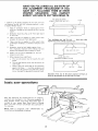
The versatility
of the Radial Saw is due, in part, to its
controls,
and these are the keys to its successful operation.
Learn to use the controls
for all operations
before actually
starting
to saw.
A series of six diagrams is located on the top surface of the
arm. These designate the controls that must be used in basic
set-ups
and operating
procedures.
You should
become
familiar
with these diagrams and the operating
instructions
that follow,
before operating
your saw.
MITER
INDICATOR
2
5
ARM
BEVEL INDEX
RIP SCALE
CARRIAGE
CONTROL
LEVER
BLADE
ANGLE
{BEVEL)
LEVER
INDICATOR
3
b
SWIVEL
LATCH LEVER
ON-OFF
SWITCH
WITH KEY
ARM
LOCK
WHEEL
TABLE CLAMP
GUARD CLAMP
SCREW
ELEVATION CRANK
\\
4
CARRIAGE
LOCK KNOB
3
LOCK
HANDLE
7
BRAKE
ANTIKICKBACK,
SPREADER
ADJUSTING
WING
SCREW
8
{ SHAFT
ANTIKICKBACK
AND SPREADER
ASSEMBLY
BEVEL INDEX
INDICATOR
5
BEVEL LOCK
LEVER
locations
Depth
and functions
of controls
of Cut (Elevation)
a.
The diagram
shows the elevation
crank
used to raise and lower the saw blade.
b.
Clockwise
rotation
raises
the
which
saw-blade
bevel-index
is
2.
Angle
of Cut
moving
the
arm
to
a
miter
position
move it slightly
past the desired index position,
then return to the index position
carefully
to index and
lock.
Yoke
indexing
and bevel
indexing
can be
accomplished
in a similar
manner.
This
indexing
technique
tends to neutralize
any stresses impaired
upon
saw components
and contributes
to the high
degree of accuracy
the saw is capable of producing
when operated expertly.
The arm control
lever locks, unlocks
the arm for Left and Right Miter cuts.
and
b.
The radial arm has positive
index positions
at 0 °
and 45 ° Left and Right.
The arm is rotated
by
pulling
arm control
lever to index release position.
With
arm
control
lever
released
the arm
will
lock
lever
and
c.
The bevel index lever automatically
indexes
the
motor
at 0 °, 45 ° and 90 ° . Move bevel index lever
d.
index
a.
bevel
to the left while positioning
the blade, then
it. At any other position
it does not engage.
6.
When
are:
The bevel-index
scale indicates the angular position
of the motor with respect to horizontal,
from 0 ° to
90 ° in either vertical position.
(Miter)
Proper Indexing
Method
Experienced
operators
of
woodworking
equipment,
such as this Craftsman
Radial
Saw, acquire
the habit of indexing
in one direction
only, whenever
a new setting is made in preparation
for
a different
operation.
Example:
angle,
b.
blade
counterclockwise
rotation
lowers it. One complete
turn of the handle will raise or lower the saw blade
1/16-inch.
(bevel)
lever.
The bevel lock lever locks the motor
when the motor
is in any position.
release and push to lock.
Power
Switch
key
release
to the yoke
Pull lever to
and Key
a.
Insert
into switch
lock.
b.
Insert finger under end of switch
out, to turn switch on.
indexes
lever and pull end
automatically
index at 0 ° and 45 ° Left or Right.
After
positioning
arm to the desired miter angle,
push arm control
lever to locked position.
LOCK
UNLOCK
INDEX RELEASE
C.
3.
Yoke Pivot
a.
Two
5.
are used in this
latch-pin
lever
operation.
and
the
They
yoke
c.
The yoke
clamp
handle
locks the yoke
to the
carriage
in any position.
Pull the handle forward
to
release the yoke; push the handle rearward to secure
the yoke.
d.
Lock
a.
The carriage lock knob is rotated
clockwise
to lock
the carriage on the radial arm, and counterclockwise
to release it.
b.
When
performing
crosscutting
operations
the
carriage
lock
knob
must
be
rotated
counterclockwise
until the carriage is free to travel
along the arm. This knob should be tightened
until
the operator
is ready to grasp the bevel index
handle and make a cut.
a.
The two
indexing
off.
are:
A swivel latch lever automatically
indexes the yoke
at each 90 ° position.
Pull the spring-loaded
swivel
latch-lever
forward
to release this pin.
Blade Angle
-- to turn switch
clamp
b.
Carriage
thumb
(Ripping)
controls
the swivel
handle.
4.
Push lever in -- with
(Bevel)
controls
of the
used in angular
positioning
and
motor,
to provide
the desired
20
WARNING:
THIS
LOCKING
FEATURE
IS
PROVIDED
TO PREVENT
UNAUTHORIZED
USE OF YOUR SAW. ALWAYS REMOVE THE
KEY AND KEEP IT IN A SAFE PLACE. TO
REMOVE
KEY, HOLD THUMB ON END OF
LEVER TO KEEP SWITCH IN "OFF" POSITION
AND PULL KEY STRAIGHT OUT.
WARNING:
FOR YOUR OWN SAFETY
ALWAYS
LOCK THE SWITCH
"OFF"
WHEN SAW IS NOT
IN USE. REMOVE
KEY AND KEEP IT IN A SAFE
PLACE . . . ALSO IN THE EVENT
OF A POWER
FAILURE
(ALL YOUR
LIGHTS
GO OUT) TURN
SWITCH OFF. LOCK IT AND REMOVE
THE KEY
THIS
WILL
PREVENT
THE
SAW
FROM
STARTING
UP AGAIN
WHEN
THE
POWER
COMES BACK ON.
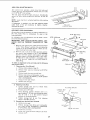
7.
8.
The Manual
Motor
la.
Pressing on the brake button
with finger or thumb,
after turning
off the ON-OFF
switch,
will greatly
reduce blade coasting time.
remove
the accessory
shaft
shaft
at
such
it will
Use only
the following
chuck,
adapter.
CAUTION:
The sawblade, dado, or cutting
tool must
be removed
from
the saw arbor
before
using the
accessory shaft. NEVER
operate the saw with cutting
tools (including
sanding accessories)
installed
on both
ends of the saw arbor.
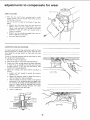
POSITIONING
GUARD,
ANTIKICKBACK
SPREADER
ASSEMBLY,
FOR RIPPING
-to
in
on
sawblade
and
sawblade (failure
to use spreader),
set of teeth of sawblade.
and/or
inadequate
act as a partial guard regarding
with the sawblade at the outfeed
and leading edge when crosscutting.
accidental
side when
contact
ripping,
a. The blade guard is positioned
by loosening
the
guard clamp screw and rotating
the guard so that
the "nose"
just clears the workpiece
as shown.
AND
b.The antikickback
and spreader assembly
adjusted
to accommodate
the thickness
WARNING:
NEVER
POSITION
THE GUARD
OR
ANTIKICKBACK
ASSEMBLY
WITH THE POWER
ON.
NEVER
POSITION
THE
ANTIKICKBACK
PAWLS
BY
GRASPING
THE
PAWLS
OR
SPREADER.
_)
closing
"Wrong-way
feed" occurs when the teeth themselves
cut, or attempt
to cut, a kerf in the workpiece.
This
differs from a "kickback"
which is generated
by the
sides (one or both) of the teeth, because of binding
between the fence (heel), pinching
of the sides of the
accessories:
and Router
from
extremely
hazardous
because the sawblade may grab
the workpiece
and throw
it violently
toward the nose
of the guard (infeed side of the tool). Danger label on
guard.
as a drill
chuck
be necessary to
the accessory.
drum,
kerf
kickback;
-to
prevent
"wrong-way
feed".
"Wrong-way
feed"
is
feeding
the workpiece
-- when sawblade
is in a rip
position
-- into the outfeed
side of the cutting
tool
(sawblade,
dado,
molding
head,
etc.),
the
side
containing
the antikickback/spreader.
This can be
cover.
recommended
Sanding
prevent
possible
Motor spacer, both blade collars and shaft nut
must be installed when using accessory shaft.
Be sure to re-install
the accessory shaft cover
after removing
Drill
motor
if generated.
Spreader
Shaft.
When using an accessory
to end of motor
shaft,
CAUTION:
on the
is used during
accommodate
A wing screw
are necessary:
-- to stop a kickback
-to
The manual brake is located
the right-hand
end of motor.
Accessory
The antikickback
and spreader assembly
ripping
operations
and is adjustable
to
the thickness
of the board being ripped.
in the guard secures the assembly.
These adjustments
Antikickback
Brake.
a.
NOTE:
attached
2.
board
being
ripped.
secures the assembly.
A
wing
screw
in
must be
of the
the
guard
SPREADER
GUARD
ANTIKICKBACK
PAWL
DIRECT%
OF KICKBACK
'NFEED
DIRECTION
_l EO_K __
NOSE OF J
GUARD
1.
OF FEED
MINIMUM
ANTIKICKBACK
GUARD CLEARANCE
The blade guard is positioned
by
clamp screw and rotating
the guard
clears the workpiece
as shown.
loosening
the guard
so that the nose just
3.
This is necessary:
to protect
operator
from accidentally
contacting
sawblade radially from the Infeed direction.
to hold down
the workpiece
minimizing
lifting
or fluttering
and/or light workpieces);
to minimize
DIRECTION
O UsTFEEED
sawdust
thrown
N
Loosen
the wing
screw and with
the tab provided,
position
the antikickback
and spreader assembly until
the pawl assumes approximately
the position
shown
above. Tighten the wing screw.
(Make sure by trial
before
starting
the cut that the
antikickback
pawls will stop a kickback
once it has
started).
Insert
workpiece
alongside
spreader
under
outer
set of pawls by approaching
pawls in the feed
direction.
Push workpiece
sharply in the direction
of a
kickback
(opposite
to direction
of feed).
Readjust
Pawls if they do not stop the kickback
motion
by biting
into the workpiece.
against the table (particularly
thin
toward
- to minimize
the possibility
of
riding up on top of the workpiece
of workpiece.
the
POSITIO
the operator.
a thin pusher
board
with loss of control
21
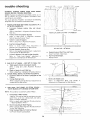
HA VE YO U FOL L 0 WED A L L SIX S TEPS 0 F
THE ALIGNMENT
PROCEDURE?
IF YOU
HAVE NOT
FOLLOWED
THEM IN THEIR
PROPER
SEQUENCE,
YOU
CANNOT
EXPECT
A CCURA TE CUTTING
RESUL TS.
THIS EDGE OF BOARD
AGAINST FENCE FOR ALL CUTS
/
_, addition
to the proper alignment
of your saw, you must
also become familiar
with the following
practices
in order
to expect the best results.
1.
Edge of workpiece
must be as straight
square.
2.
Workpiece
is placed against fence
long side of your framing
table
board
There
must be no sawdust
or other
wood
between the fence and front table board.
chips
4.
There
must be no sawdust
or other
wood
underneath
workpiece
or between
workpiece
fence.
chips
and
5.
Workpiece
must be held tightly
against fence . . .
this is especially
important
when making angle cuts
because the workpiece
has a tendency
to move.
6.
Always
Always
7.
When
on your
3.
must
which
as the
be as flat
as the front
FENCE
,
/
I
t,
saw.
use the correct
keep it sharp.
making
a four sided
side
pieces
Sawblade
for
the
Job
Turn workpiece
over end for end . . . keep
against fence when making successive cuts.
. . .
PENCIL LINE FOR
GAUGING
REQUIRED LENGTH
frame:
must
a.
The two
length.
b.
The top and bottom
same length.
c.
Always
place the same edge of the workpiece
against, the fence . . . turn the workpiece
end
for end for the successive cuts and mark a pencil
line on the table for gauging the required
length.
pieces
be exactly
the
must be exactly
same
[
the
/
Deviations
from any
effect on the accuracy
basic saw
operations
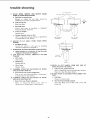
Basic saw operations
are summarized
into six categories,
explained
and illustrated
in the following
paragraphs.
A
book
entitled
"Power
Tool
Know
How
Radial Saw"
is
available
at your
Store. This book
the radial saw.
nearest
contains
Sears Retail
considerable
Store or Catalog
data applicable
to
NOTE:
Refer
to paragraphs
under
"OPERATION"
illustrations
and descriptions
of controls.
same edge
for
22
3RD CUT
SCRAP
of the above practices will
of the cuts that you make.
have
an
basic saw operations
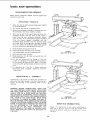
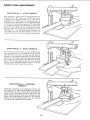
REQUIREMENTS
Board
laying
FOR CROSSCUT
position
(stationary)
flat on table top.
against
(OPERATIONS
rip
fence
1 THROUGH
(guide)
and
4)
1.
Arbor
nut must be tight
in horizontal
position.
2.
Arm
3.
Adjust the antikickback
assembly so the pawls just clear
the workpiece
or the fence, whichever
is higher.
4.
Work must be held firmly
against table and fence. For
workpieces
thicker
than the fence
is high, install
a
higher
fence
(at least workpiece
thickness).
Always
place the fence in the most forward
position
(farthest
from
the
column
support)
compatible
with
the
workpiece
being processed
and the operation
being
performed.
With the carriage fully retracted,
the blade
must not contact
the workpiece
when placed against
the fence, within the stated capacities
of your saw.
5.
Blade should
6.
Hands
7.
Yoke
8.
Bevel index
9.
Blade should cut into
more than 1/32 inch.
control
lever must be in locked
be sharp
must be kept
clamp
and saw blade
handle
and correctly
guard
installed
position.
set.
well away from
must be in locked
saw blade.
position.
(SEE
PROPER
ITEM "10"" AT
LEFT)
lever must be locked.
the
table
or plywood
cover
not
10. Pull the saw forward
just far enough
to sever the
lumber.
It is dangerous
if the blade has been pulled too
far out beyond the piece being cut. When it is returned
it can pick up the right hand piece and throw it over the
fence.
11. For operations
No.
instructions
under
"Blade Angle".
3 and No. 4, observe
paragraph
"Operating
OPERATION
additional
Controls"
No. 1 - CROSSCUT
Crosscutting
is the process of sawing the workpiece
by
pulling
the saw blade through
it and using the fence as a
support
for the edge of the workpiece.
Never crosscut
free-hand.
i_
WARNING:
BEFORE
CROSSCUTTING,
MAKE
SURE
THE
ARM
CONTROL
LEVER,
BEVEL
LOCK
LEVER
AND YOKE CLAMP
ARE ALL LOCKED.
NEVER
USE A
LENGTH
STOP OR A FIXED
GUIDE
ON THE
FREE
END OR EDGE OF A WORKPIECE.
DO NOT CROSSCUT
WORKPIECES
THAT
PLACE
YOUR
HANDS CLOSE TO
THE
PATH
OF THE
SAW
BLADE.
WHEN
MORE
IMPROPER
(SEE ITEM "10" AT
EXPERIENCE
IS GAINED
BY USING
THE
SAW,
IT
WILL
BE NOTICED,
THAT
WHEN PULLING
THE SAW
TOWARD
YOU DURING
CROSSCUTTING,
THE BLADE
TENDS
TO FEED ITSELF
THROUGH
THE WORK DUE
TO
THE
ROTATION
OF
THE
BLADE
AND
THE
DIRECTION
OF
THE
SHOULD
DEVELOP
THE
RIGHT
ARM STRAIGHT
THE WRIST.
FEED.
HABIT
FROM
REPETITIVE
THEREFORE,
YOU
OF HOLDING
YOUR
THE SHOULDER
TO
DIRECTION
OF TRAVEL
LEFT)
CROSSCUTTING
Clamp a "C" clamp
(min. 6 inch) using a wood block on
each side of the arm. This will
limit
the carriage travel
beyond
the position
necessary
to complete
the crosscut
operation.
23
basic saw operations
OPERATION
Miter crosscutting
angle other than
a popular
one,
No. 2 - MITER
!
CROSSCUT
is the process of sawing a board at any
a 90 ° (square) cut. The 45 ° miter angle is
since
two
boards
cut
to 45 ° can be
assembled to form a 90 ° corner for producing
a square or
rectangular
frame. The radial arm is set to the desired angle
of cut; yoke and bevel settings indexed at 0 ° (and locked)
as in square crosscutting.
The board being cut is held firmly
against the fence (guide) and the carriage pulled forward
along the radial arm to perform
the desired
cut. As in
"Operation
No. 1", the carriage should be returned
to full
rear position
and the saw blade allowed
to come to a
complete
stop
before
OPERATION
Bevel
crosscutting
removing
the boards
No. 3 -- BEVEL
is the
process
from
saw table.
CROSSCUT
of sawing
at 90 °
(square)
across the board with
the saw blade set at an angle other
than 90 ° to the saw table. The radial arm and yoke are
indexed
at 0 ° and locked, but the bevel is set to the desired
angle of cut. The board is held firmly against the fence and
the carriage pulled forward
along the radial arm to produce
the cut. The carriage should be returned
to full rearward
position
and the saw blade allowed to come to
stop before removing the boards from saw table.
OPERATION
a complete
No. 4 - COMPOUND
CROSSCUT
Compound
crosscutting
is the combination
of miter and
bevel crosscuts. The radial arm and bevel are set to produce
the desired cut; the yoke is indexed at 0 ° and locked. The
board
is held firmly
against the fence and the carriage
pulled forward
along the radial arm to produce
the cut.
Again,
the carriage
should
be returned
to full
rearward
position
and the saw blade allowed to come
stop before removing boards from saw table.
to a complete
24
REQUIREMENTS
WHEN RIPPING
(OPERATIONS 5 AND 6)
1.
Carriage
2.
Radial
lock knob
must be locked.
3.
Work must be held
feeding through.
4.
Guard
spreader and antikickback
mechanism must be
properly
set.
OBSERVE
INSTRUCTIONS
IN
PARAGRAPH,
"POSITIONING
GUARD,
AND
ANTI KICKBACK
AND SPREADER
ASSEMBLY
FOR
RIPPING"
UNDER
"LOCATION
AND
FUNCTION
OF CONTROLS".
arm must be locked
firmly
in 0 ° position.
against
table
be sharp and correctly
and fence while
5.
Blade Should
6.
When ripping narrow stock, less than 3 inches but more
than 1/4 inch between the guard and the fence (guide),
use a "Push Stick"
at least 1/4" thick and at least 16"
long so the workpiece
is clear of the blade before your
hand contacts the guard.
GREATER
THAN
1/4"
set.
SLIGHTLY
THICKNESS
UP
SLIGHTLY
THAN
LESS
OF
TO
THAN
WORKPIECE
3/8"
LESS
(l-INCH
90 °
SQU_J_ES)
PLYWOOD
7.
When ripping stock 1/4 inch or less between
and fence (guide) use a Pusher Board.
the
MAX.
blade
Pusher board should not be less than 3 inches wide and
16 inches long. Nail or glue a 3/4 x 3/4 x4 inch block
to one edge of pusher board to be used as a grip.
The pusher board should be fed into the blade behind
the stock being ripped until the stock is clear of the rear
of the blade (not more than 8 inches so as not to strike
antikickback
pawls)
and then
pulled
back
with
use of
MIN'_--_.
the grip.
8.
9.
_
Hands must be kept well away from saw blade.
Saw blade
MUST
be parallel
to fence,
to minimize
possibility
C_
of kickbacks.
11. The
pusher
workpiece.
the
nose
the kerf
board
- must
should
[__--_
be used.
__
,/
be the same thickness
/1_ _r-'_,,J
_ __/rr--_
//I
[
_J
as the
_1////[/{/(/_1/_._
No thinner
for strength,
or no thicker
since
of the guard must
clear the top of the
{I 141[
I ,lf
_-----,=1%1_-._1F I \_/'/I_t_
OPERATION
No. 5- OUT-RIPPING
AND IN-RIPPING
1.
_
L.._'_/f//-
10. For every new width of cut, a new PUSHER
BOARD
or a reworked
PUSHER
BOARD to remove the material
containing
/4"
_t_5_
1/4" OR LESS
WARNING:
NEVER
RIP
FREE-HAND.
BEFORE
RIPPING,
MAKE
SURE
THE
GUARD,
AND
ANTI KICKBACK
AND SPREADER
ASSEMBLY
ARE
Ripping
is the process of sawing the workpiece
by
feeding it into the saw blade when using the fence as a
guide and as a positioning
device to obtain the desired
width of cut. The sawblade is parallel to the fence.
SET UP PROPERLY.
BLADE
IS PARALLEL
RIP
WORKPIECES
BLADE
DIAMETER.
25
ALSO, MAKE
SURE THE SAW
WITH
THE FENCE.
NEVER
SHORTER
THAN
THE
SAW
2.
Since the work is pushed along the fence, it must have a
straight
edge in order to make sliding contact with the
fence. Also, the work must make solid contact with the
table, so that it will not wobble.
Provide a straight edge,
even if this means temporarily
nailing
of an auxiliary
straight-edged
board to the work.
If the workpiece
is
warped, turn the hollow side down.
3.
Always
use the saw guard and make sure the spreader is
correctly
aligned
with
the saw kerf and antikickback
pawls properly
adjusted.
Wood cut with the grain tends
to spring
the kerf closed and bind the blade and a
kickback
could occur.
4.
Stand a little
to one side
in case of kickback.
5.
When ripping
short or narrow work, always use a push
stick applied
to the section of the workpiece
between
the blade and fence ... push the work past the blade so
it is clear of the blade. This procedure will minimize
the
possibility
of kickbacks.
of center
to be clear
of work
Out-Ripping.
In-Ripping.
The radial arm and bevel are indexed at 0 ° and
locked,
but the yoke is turned
90-degrees
in a clockwise
direction
(viewed from above) from the crosscut position.
Thus, when standing
in front of the saw, the blade would
be rotating
counterclockwise.
After
positioning
the guard
and antikickback
mechanism
the workpiece
is fed from the
right-hand
side of the saw. The "Blade
In-Rip'"
scale is on
the left-hand
side of radial arm.
OPERATION
Bevel ripping
above, except
the saw table
No. 6 -
BEVEL
The
and
locked,
counterclockwise
but
crosscut position.
would
be rotating
and antikickback
left-hand
side of
the left hand side
radial
arm
and
bevel
are indexed
the yoke
is turned
direction
(viewed from
at 0 °
90-degrees
in a
above), from the
When standing
in front of the saw, blade
clockwise.
After positioning
the guard
mechanism
the workpiece
is fed from the
the saw. The"Blade
Out-Rip"
scale is on
of radial arm.
RIPPING
is either in-ripping
or out-ripping
as described
the saw blade is tilted out of perpendicular
to
surface. The radial arm is indexed at 0 ° and
locked,
the bevel is set to the desired bevel angle and the
yoke
is positioned
for in-ripping
(saw blade at rear) or
out-ripping
(saw
blade
at front),
as required.
All
requirements
and observations
applicable
to normal
ripping
operations
also apply to bevel ripping.
DADOING
MOLDING/SANDING
Instructions
for operating
the Dado Head are contained
booklet furnished
with the Dado Head.
in
Instructions
in a booklet
The saw arbor
is designed
for dado heads up to 13/16
inches wide. Do not install a wider dado head on the arbor.
Take several
When
install
passes if required
dado cut exceeds
13/16
arbor
outer
installing
the dado head on the arbor,
ALWAYS
the inside "loose
collar"
first.
Be sure the teeth of
NOT
install
the
outside
loose
nut is tight.
Install the arbor
blade of dado head.
collar.
nut
Make
directly
sure
the
against
the
For best results and to avoid excessive load on the
NEVER
CUT A 13/16"
WIDE
DADO,
DEEPER
3/4" IN ONE PASS.
NEVER
USE A DADO HEAD OR MOLDING
HEAD
ADJUSTING
A MOLDING
HEAD/DADO
GUARD.
REAR
TA _
,E
motor,
THAN
WITH
Head are contained
Head.
For use of Molding
Head Cutter or Drum Sander the rear
table requires
an opening
(next to rear face of fence) for
clearance.
Cut this opening as shown.
inch.
the chippers
are placed to fall in blade gullets, and chippers
are approximately
equally spaced around the arbor.
DO
for operating
the Molding
furnished
with the Molding
THE
26
SAW
ARBOR
VERTICAL
-'''
4
WITHOUT
l
INSTALLING
AND
adjustments
ADJUSTING
1.
to compensate
for wear
BEVEL LOCK LEVER
The purpose
of this lever is to lock the motor at any
angle. To adjust,
remove the set screw with wrench as
shown.
Use the bevel lock lever as a wrench to tighten
the clamp
bolt.
Do Not Over Tighten.
Replace bevel
lock lever in locked position
and tighten
the set screw.
BEVEL LOCK
LEVER
/
V
!
1/8 HE× "k" WRENCH
IN LOCKED POSITION
YOKE
1.
LOCK
HANDLE
ADJUSTMENT.
This handle provides
a friction
face of the yoke and the bottom
lock between
the upper
face of the carriage.
It should eliminate
any play or rotation
between
these
two
parts when locked.
Its proper
position
for saw
operation
is approximately
midway'_between
t_ne two
sides of the yoke.
HEX
When sufficient
wear has occured to permit
the handle
to move considerably
to the rear, or strike the yoke
before locking,
the handle must be adjusted
as follows:
2.
Remove carriage stop screw
inch hex-L wrench.
3.
Grasp the carriage assembly,
move it carefully
off the
end of radial arm, holding
it parallel to the radial arm
until all carriage bearings are free of their tracks.
4.
Rest
table
and Iockwasher
with
a 1/4
LOC
CARRIAGE
STOP
SCREW
the motor
and carriage
assembly
on saw work
and re-install
carriage stop screw and Iockwasher.
To Readjust
5,
Set yoke lock handle
with
15/16 wrench,
15/16
at unlocked
position.
Tighten
nut
until
lock handle
locks mid-way
between
the two sides of
stop screw and Iockwasher.
the
yoke.
Remove
carriage
6.
Hold the motor and carriage assembly parallel to radial
arm
and start
the
rear bearings
onto
the tracks.
Continue
to hold the assembly
parallel
to the tracks
until the forward
bearings are on the tracks.
7.
S!ide
the carriage
rearward
INSTALL
THE
CARRIAGE
LOC KWASH E R.
on
the
STOP
'I."
(I/4
radial
arm and
SCREW
AND
27
WRENCH
WRENCH
INCH)
adjustments
to compensate
for wear
3/8-16
ARM
BOLTS
TO COLUMN
With
the arm control
lever unlocked
release position,
the arm should
move
vertical play in the arm.
The arm
adjust.
should
fit
snugly
on the
and
firmly
column.
in index
with no
If not,
then
a.
Remove
four (4) screws from rear cover plate and
tighten
evenly
top two
3/8-16
bolts,
until
arm
moves firmly
and there is no vertical
or horizontal
movement
in the arm when arm control
lever is
locked o_ unlocked.
b.
Bottom
two nuts should be snugged
nearly as tight as top two bolts.
c.
Re-Install
ADJUSTING
evenly,
©
but not
Rear Cover Plate.
CARRIAGE
BEARINGS
In proper
adjustment
the top and bottom
radii of all four
bearings should be in contact
with the arm tracks for their
entire length and carriage should roll freely but with some
resistance.
To test for looseness between
bearings
arm, perform
the following
steps.
left-hand
carriage
cover.
to its full
most
and tracks
on radial
1.
Remove
2.
Push the carriage
3.
Finger hold front
carriage bearing as shown and apply
as much force as possible and at the same time pull
carriage
forward.
If you
can stop the bearing
from
turning
it will require adjusting.
4.
Check rear
follows:
bearing
in the
rearward
position.
same manner
the
eccentric
b.
Rotate the eccentric
screws a partial
right) as required to take up looseness.
C.
Hold the heads of eccentric
screws in the position
established
in the preceding
step and tighten
nuts
on underside
of carriage. Correct
adjustment
exists
when you cannot
keep the bearings from turning.
However,
excessive
bearing
pressure
will
cause
difficult
operation
and rapid wear.
carriage
permit
as
Loosen
nuts just
screws to turn.
Install
to
adjust
a,
d.
enough
and
turn
(left
or
cover.
_%"C ARR IAGE
BEARING
CARRIAOE
LOCKWASHER
PLAIN
WASHER
1_...
NUT
28
ARM
LOCK
ADJUSTING
WHEEL
Arm control
lever operates
a brake shoe that
releases the arm, and automatically
releases the
pin for 0 ° & 45 ° miter settings.
locks and
arm index
The lock action should feel tight and secure. Considerable
amount
of effort
must be applied to the lever to lock the
arm.
NOTE:
Lever
adjustment.
must
be in unlocked
If adjustment
is required,
under
front
of the arm
clockwise
to loosen.
ARM
INDEX
ROD
position
turn arm
clockwise
while
making
lock adjusting
wheel
to tighten,
counter-
ARM
An indication
that
oqe of the following
this adjustment
occurs:
IMPORTANT:
ARM
ABOVE)
MUST
BE
TIME.
must
be made
to
the
LEVER ARM KNOB
is when
LOCK/ADJUSTING
WHEEL
PROPERLY
ADJUSTED
AT
MITER INDICATOR
g _r_
moved out of the Indexed
fully retracting
from Index
position.
ring).
(Index
_
position
(with the column
tube supports
and gibs
adjusted
properly
eliminating
all play in this area).
A slight side to side movement
is noticeable
at the
front
of the arm. (Index
pin not fully
seated in
Index Ring).
2.
Removing
b.
Remove miter
Head screws.
scale
c.
Remove
from
d.
Remove stop screw and Iockwasher
in arm.
Remove carriage.
RE-INSTALL
STOP SCREW
AND LOCKWASHE
R.
e.
Grasp arm trim
f.
Remove arm trim
indicator.
knobs
arm control
LEVER
CARRIAGE
STOP
SCREW
;
_
two
#10
Pan
lever.
and remove.
pad.
Rod.
carriage
bracket
b.
Position
arm in 0 ° Index.
c.
Bring
adjusting
bracket
approximately
1/16 inch
rod.
Or until
it is in
position
on the mounting
bolt
and
in place.
Tighten
carriage
action in all Index
Reinstall
Z_
Snap fit.
by removing
Loosen
adjusting
d.
ARM CO N TROL
Trim (Shroud)
miter
Index
__"_"""_
CARRIAGE
Remove
Adjusting
PAD
to the arm Index rod the following
a.
a.
3.
Arm
4Z-----_4_ ARMTRIM
_l
pin not
With the arm in one of the Index positions
and the
arm control
lever allowed
to rest in the Unlocked
To make an adjustment
steps must be taken.
_1
(SEE
THIS
With the arm control
lever pulled forward
and held
in the "Index
Release" position,
the arm cannot be
1.
WHEEL
ADJUSTMENT
At some time it may be necessary to make an adjustment
the Arm
Index
Rod, to compensate
for wear
in
Indexing
System.
2.
LOCK
ADJUSTING
parts that
arm trim
nut
which
holds
ADJUSTING
CARRIAGE
BOLT
AND
NUT
forward
until
it is
from contacting
Index
the extreme
forward
slot.
bolt
&
positions.
nut.
Test
BRACKET
INDEX
ROD
indexing
have been removed.
a.
Install
b.
Remove
Carriage Stop Screw and Lockwasher
and install carriage.
REINSTALL
CARRIAGE
STOP SCREW, AND LOCKWASHER.
pad.
c.
Install
d.
Install miter scale and miter
indicator
to 0 °.
MOUNTING
SLOT
1/16-INCH
lever arm knob.
indicator.
Set miter
29
trouble-shooting
FINISH CUT END
SQUARE
SQUARE
\
WARNING:
REMOVE
POWER
CORD
SOURCE
BEFORE
TROUBLE
SHOOTING.
FROM
POWER
NOTE: Changing one adjustment
will effect another,
best to perform
all of the alignment
procedures
correcting
any one problem.
The usual
paragraphs
1.
operating
"troubles"
are listed in the
with the necessary corrections
listed.
RADIAL
SAW DOES NOT
45 ° MITER
CROSSCUTS.
a.
Looseness
between
MAKE
so it is
when
following
ACCURATE
column
tube
0 ° or
and
column
Procedure
Section
support.
b.
FENCE EDGE
Align as described
Step Two.
in Alignment
Crosscut
properly
Refer
Section
travel
FINISH CUT LOOKS LIKE THIS--
not
to
Step
Squaring
FENCE EDGE
0° CROSSCUT
adjusted.
Three
in Alignment
Crosscut Travel.
c.
Column
Refer to Step Two
in Alignment
d.
Arm
Properly.
Procedure
is Loose in Support.
Procedure.
l
Not Indexing
Refer
to
Arm
Adjustments
e.
f.
Carriage
Assembly
Yoke
ANGLE
-
One
90 ° TO TABLE
not properly
under
Four in Alignment
ANGLE
a.
Corrective
B above.
b.
Carriage
h.
in
-- 45 ° MITER.
between
Work
Work
Piece and Fence.
Table
Clean.
Rip Fence Not Straight.
Replace
TOP.
Fence.
SHOULD BE 90 °
ANGLE
Procedure
(BEVEL)
Action
Bearings
Procedure
CUTS NOT
Section.
j
ACCURATE.
is the same as paragraph
2A
and
in adjustments
to
This condition
Crosscutting
[
C.
is commonly
or Miter
called
Bevel Lock
Refer
to
Adjustment
Handle
Loose.
Adjustment
to Compensate
Bevel
Lock
Handle
for Wear Section.
'
--
ROUGH KERF Z_]_/--_WlDE
EDGE
"HEEL".
_--'_]'_
Procedure
Using
Improper
Use Proper
BLADE
Section
Or Bevel Ripping.
Refer to Step 5 Under Alignment
Vertical
Heel Adjusting.
c.
CUT_
(KERF)
Cutting
Refer to step 5 under Alignment
- "Squaring
Blade to Fence."
Bevel Crosscutting
in
FENCE
I
"Heeling"
will tend to slide the workpiece along the
guide fence, as the cut is being made, and make a
square cut almost impossible.
b.
BOARD
SQUARE
Loose.
SAW
KERF
(CUT
EDGE)
OF STOCK
ROUGH
TOOTH
MARKS LEFT ON EDGE OF SAW KERF.
a.
THIS
Blade not square to work table top.
BLADE
NOTE:
Sawdust
leveled.
Alignment
Refer to adjusting carriage bearing
compensate
for wear section.
4.
LIKE
Keep Front
Handle"
adjustment
for Wear Section.
NOT
Table support channels
Step
g.
and Carriage
"Yoke
Lock
to Compensate
AT
Tl,l,l,l,l,l,l,l,l,l,l,l,l,ld,[,I,i,l,l.,I,t,
OR
Assembly.
CUTS
i,i
Loose on Arm.
between
Refer to Step
3.
in
Looseness
Refer to
Section.
b.
Adjustment
in adjustment
SAW
a.
Rod
for Wear section.
Refer to Carriage Bearing Adjustment
to Compensate
for Wear Sections.
Refer
to
adjustment
2.
Index
to Compensate
1
Blade for
Smooth
Cutting
Finish
Procedure
Cut
Section
:C
-
Desired.
Blade.
-----
DIRECTION OF tH
DIRECTION OF--
BLADE TRAVEL
ATTEMPTED /_
.BLADE TRAVEL
,/-¢.
30
....
--
--_
trouble-shooting
IN
5.
WOOD
DOWN
a.
BINDS,
OR STOPS
Dull blade or warped
Sharpen
attempted
b.
MOTOR
e.
VIEW
Avoid
the
FENCE
90 c
_
TO
THE
FENCE
F[NC[
_'''_
DIRECTION
FEED
Saw blade heels.
in
Alignment
Fence not straight.
Replace
fence.
Carriage
Assembly
Loose on Arm.
PULLS
AWAY
FROM
in adjustments
HEEL
TO
RIGHT:
HEEL
I NCORRECT
FENCE
TO
LEFT:
I NCORR ECT
WHEN
RIPPING.
FENCE
Saw Blade
has heel.
Corrective
instructions
7.
ARM
Feed Rate.
BOARD
a.
RIP POSITION
WITH
t
Refer to adjusting
carriage bearings
to compensate
for wear section.
6.
TOP
board.
or replace
the
saw blade.
use of severly warped material.
Check
and
align
as described
Procedure Section,
Step Five.
d.
SLOWS
Feed rate too fast.
Slow
c.
SMOKES
AND
WHEN
RIPPING.
WORKPIECE
action
explained
STRIKES
is the
same
as
in paragraph c.
SPREADER
WHEN
preceding
RIPPING.
a.
8.
Adjust spreader per instructions
in Step Six under
"Alignment
of Spreader for Ripping".
SAW
DOES
NOT TRAVEL
SMOOTHLY
ON ARM
PARALLEL
TRACKS.
a.
Dirty
WITH
FENCE
tracks.
Clean Tracks.
b.
Bad Bearing.
Replace
c.
Worn Tracks
Replace
9.
CORRECT
Bearing.
11. DEPTH
WORK
Tracks
CLAMPING
FORCE
NOT SUFFICIENT
ANGLES
OTHER
THAN 45 ° .
a.
Arm
Control
Lever requires
Bevel Lock
Refer
to
Adjustments
Lever
Requires
a.
MITER
Table
Top not parallel
with
ONE
in Adjustments
AT
BEVEL
TENDS
a.
Blade.
Dull
Replace
b.
adjusting.
Adjusting
Bevel
Lock
Lever
to Compensate
for Wear Section.
12. BLADE
FAST.
in
31
Not
TO ADVANCE
or sharpen
advancing
Draw
Saw
steady
pull.
OF
THRU
Mtg. Support
LUMBER
TOO
blade.
Saw Blade
Blade
END
Arm.
Refer to Attaching
and Leveling table
Channels in Step One Align. Section.
Adjustment.
Refer to Arm Lock Adjusting
Wheel
to Compensate
for Wear Section.
10. CLAMPING
FORCE
NOT SUFFICIENT
ANGLES
OTHER
THAN
45 ° .
a.
AT
OF CUT
VARIES
FROM
PIECE TO THE OTHER.
across
properly.
lumber
with
a slow
and
MOTOR
TROUBLE
- SHOOTING
CHART
NOTE:
Motors used on wood-working
tools are particularly
susceptible
to the accumulation
of sawdust and wood chips
and should
be blown
out or "vacuumed"
frequently
to
prevent interference
with normal motor ventilation.
TROUBLE
Motor
will not run.
Motor will not run and
fuses "BLOW".
PROBABLE CAUSE
1. Low
voltage.
1. Short circuit
in line,
cord or plug.
2. Incorrect
Motor fails to develop
full power. (Power output
of motor decreases rapidly
with decrease in voltage at
motor terminals. For
example: a reduction of
10% in voltage causesa
reduction of 19% in
maximum power output
of which the motor is
capable, while a reduction
of 20% in voltage causes
a reduction of 36% in
maximum power output.)
Motor
overheats.
1. Check
1.
Power
line overloaded
Undersize
too long.
REMEDY
line for proper
voltage.
1. Inspect line', cord and plug for damaged
insulation
and shorted wires.
fuse in power
lights, appliances
m ot o rs.
power
SUGGESTED
line.
with
2. Install
15 amp Time
1. Reduce
the line load.
wires or circuit
wire
3. General overloading
of
power company's
facilities.
(In many sections of the
country,
demand for
electrical
power exceeds
the capacity of existing
generating
and distribution
systems.)
3. Request
a voltage
1. Excessive
1. Slow
crosscutting
2. Improper
circulation
feed rate when
down
sizes, or reduce
check
cooling.
(Air
restricted
from
the power
company.
3. Refer to Alignment
manual Step Five.
Procedure
condition.
1. Low Voltage - will
starting switch.
not trip
1. Correct
2. Blade teeth
into
2. Free blade from
Motor stalls (resulting
in
blown fuses or tripped
circuit breakers).
1. Voltage too low to permit
motor to reach operating
speed.
1. Correct
2. Fuse or circuit
breaker
do not have sufficient
2. Replace fuse with 15 amp
Time Delay Fuse.
wedged
table.
low voltage
overloaded.
I. Reduce
have
the low line voltage
motor
load.
2. Replace fuse with
Time Delay Fuse.
capacity.
32
Section
table.
capacity.
2. Fuse does not
normal
air
due to
Motor starts slowly or
fails to come up to full
speed.
sufficient
of wiring.
rate of feed.
2. Clean out sawdust to provide
circulation
through
motor.
3. Saw blade has "heel".
1. Motor
length
or ripping.
through motor
sawdust, etc.)
Frequent opening of
fuses or circuit breakers.
Fuse.
and other
2. Increase
2.
Delay
15 amp
condition.
of
maintenance
and lubrication
MAINTENANCE
NO LUBRICATION
Do not lubricate
carriage ball bearings or motor
these
are sealed
ball
bearings
and require
lubrication.
WARNING:
FOR YOUR
OWN SAFETY,
TURN
SWITCH
"OFF"
AND
REMOVE
PLUG
FROM POWER
SOURCE
OUTLET
BEFORE
MAINTAINING
OR LUBRICATING
YOUR SAW.
Do not lubricate
When
you
receive
your
new Craftsman
radial
saw, it
requires
no lubrication.
The radial saw has been partially
aligned and all bearings are lubricated
and sealed for life. In
time,
however,
in order
to keep your saw in perfect
working
order and accurate, it will be necessary to lubricate
and realign.
In fact,
your
radial
saw needs more of a
cleaning than a lubrication.
Make sure the teeth
always sharp. Replace
of the ANTI
if not sharp.
KICKBACK
pawls
between
PERIODICALLY
radial
bearings as
no added
arm cap and radial
LUBRICATE
THESE
arm.
POINTS
Use SAE No. 10W-30 automotive
engine oil and refer to
Parts List for locations.
Apply a few drops of oil along the
swivel latch pin and bevel index pin only if the pin has a
tendency
to stick.
use oil sparingly
bearings or races.
are
Remove the left-hand
carriage cover and
to prevent
it from
getting
on the ball
A light film
of oil should
be wiped
on the face of the
column tube to lubricate
the fit between the column tube,
and column support.
LUBRICATION
The
thread
on the
elevation
lubricated
through
the oil hole
arm cap.
Your saw is precision
built and should be kept clean and
properly
lubricated.
Before
describing
the various points
which
may periodically
require lubrication,
IT IS MORE
IMPORTANT
TO
FIRST
MENTION
THE
VARIOUS
POINTS WHICH SHOULD
NOT BE LUBRICATED.
accessories
ITEM
CAT.NO.
Stand
..................................
Steel Legs ...............................
Casters
.................................
Key Chuck
...............................
*Molding
Head Guard - 7-inch
*Molding
Head Guard - 8-inch
...............
...............
9-22205
9-22238
9-22208
9-2980
9-29524
9-29523
Rotary Surface Planer - Carbide Tip
..........
Sanding Wheel - 8-inch
.....................
Sanding Wheel - 10-inch
...................
Dust Collector
...........................
Dust Collector
...........................
Taper Jig .................................
*Satin Cut Dad• - 7-inch
.....................
*Satin Cut Dad• - 8-inch
.....................
*Molding
Head Single Cutter
..................
*Molding
Head Three Cutter
..................
9-29513
9-2274
9-22723
9-16998
9-29517
9-3233
9-3257
9-3253
9-3215
9-3221
Sanding Drum - 3-inch
....................
• Lower Retractable
Guard
...................
"Power Tool Know How Handbook"
Radial Saw ..............................
9-25246
9-29009
*Before
purchasing
or using
9-2917
any of these accessories,
and comply
with additional
on p. 4 of this manual.
safety
• Meets OSHA
as of 8-73.
Requirements
shaft
assembly
can be
in the center of the radial
CAUTION:
Excessive
oil at any
airborne dust particles and sawdust.
I
recommended
REQUIRED
instructions
The above recommended
accessories are current
available at the time this manual was printed.
33
read
No. "(D)2"
and were
location
will
attract
6
/
/
\
1
_ _'
/
\\ / / / t
/
/
/ / / /
/
/
/
\
\
3A
A
figur e 1
J
J
J
J
J
J
J
J
J
J
J
J
J
J
J
PARTS LIST FOR CRAFTSMAN
MODEL NUMBER
10-INCH RADIAL
113.19760
SAW
Always order by Part Number -- Not by Key Number.
FIGURE
Key
Part
No.
No.
1
2
3
4
5
6
7
8
9
10
11
12
13
14
15
16
17
18
19
20
21
22
23
24
25
63518
37818
60339
60353
63625
63719
63717
63718
63686
125525
436594
STD 551010
63671
STD 541110
STD 551131
942162O
STD 512520
63721
63432
63720
102711
STD 551025
STD 512510
Key
No.
Description
Cord, with Plug
Relief, Strain
*Screw, Hex Hd. Locking,
1
3/8-16
x 2-1/4
*Washer, .380 x 47/64 x 1/8
Arm, Rear
Cap, Radial Arm
Indicator,
Miter
Trim Assembly
Pad, Arm Trim
Nut, Square 3/8-16
Screw, Pan Hd. 10-32 x 1-1/2
*Washer, 13/64 x 7/16 x 1/16
Knob, Lever Arm
*Nut, Hex 10/32
Arm Assembly,
See Fig. 4
* Lockwasher,
5/16
Screw, Soc. Hd. Cap 5/16-18 x 1/2
Yoke Assembly,
See Fig. 2
*Screw, Pan Hd. 1/4-20 x 1-3/4
Table, Rear
Fence, Rip
Table, Front
Screw, Set SI. Cup 1/4-20 x 1
*Washer, 17/64 x 5/8 x 1/32
*Screw, Pan Hd. 1/4-20 x 1
Part
No.
26
27
28
29
30
31
32
33
34
35
36
37
38
37384
37530
STD 651125
STD 541025
STD 541431
STD 551031
63536
39
40
41
42
43
44
45
46
-
63258
3O5O5
63683
63682
63062
3540
63769
63723
63724
63722
STD 541437
63666
STD 601103
63467
60342
*Standard Hardware Item - May be Purchased Locally.
Description
Nut, Tee
Nut, "U" Clip
* Lockwasher,
1/4
*Nut, Hex 1/4-20
*Nut, Lock 5/16-18
*Washer, 21/64 x 9/16
Clamp, Table
x 1/16
Base Assembly,
See Fig. 3
*Nut, Lock 3/8-16
Plate, Rear Cover
*Screw, Tyl_e T Pan Hd. 10-32
Cap, Flag Termir_al
x 3/8
Bolt, Sq. Hd. 3/8-16 x 2-1/4
High Strength
Guard Assembly,
See Fig. 5
Elbow, Dust
*Wrench, Hex "L" 1/8
Wrench, Hex "L" 3/16
Wrench, Hex "L" 1/4
Wrench, Shaft
Wrench, Arbor
Table Spacer
Bag, Loose Parts (Not Illustrated)
Bag, Loose Parts (Not Illustrated)
Owners Manual (Not Illustrated)
PARTS LIST FOR CRAFTSMAN
MODEL NUMBER
10-INCH RADIAL
113.19760
SAW
m|
"0
42
4O
Oo
41
43
45 37
o_
47
46
3O
\
29
28 29
5O
51
\
/
52
39
Figure 2
53
PARTS LIST FOR CRAFTSMAN
MODEL NUMBER
FIGURE 2-
Key
No.
Part
No.
10-INCH RADIAL
113.19760
YOKE ASSEMBLY
Key
No.
Description
SAW
Part
No.
Description
i=
t,_
1
2
3
4
5
6
7
8
9
10
11
12
13
14
15
STD 601105
63661
30530
63679
STD 510605
120399
63657
63655
63658
63656
STD 551031
STD 551131
STD 523107
37387
60336
16
17
18
19
20
21
22
23
24
25
26
27
28
29
30
63117
60040
STD 541462
STD 551062
30567
37388
63528
63659
63660
30521
63641
STD 541231
30495
30494
60175
*Standard
*Screw, Type "T" Pan Hd. 10-32
Cover, L.H. Carriage
Nut, Speed
Indicator,
Rip
*Screw, Pan Hd. 6-32 x 1/2
x 1/2
Nut, Square 5/16-18
Housing, Index Pin
Pin Assembly,
Index
Spring, Index
Bracket, Spring
*Washer, 21/64 x 3/4 x 1/16
*Lockwasher,
5/16, Ext. Tooth
*Screw, Hex Hd. 5/16-18 x 3/4
Screw, Eccentric
Bolt, Hex Hd. 5/16-18 x 1-1/2
High Strength
Bearing, Carriage
*Washer, 21/64 x 3/4 x .062
*Nut, Lock 5/8-11
*Washer, .630 x 1.125 x .093
Bumper
Bearing, Sleeve
Shoe, Rip Lock
Cover, R.H. Carriage
Knob Assembly
Spring, Swivel Latch
Carriage
*Nut, Hex Jam 5/16-18
Nut, Shaft
Collar
1Blade, Saw
Hardware
Item
-
May be Purchased
Locally.
tStock
Item - May be secured through the hardware
departments
of most Sears Retail Stores or Catalog
Order Houses.
31
32
33
34
35
36
37
38
39
4O
41
42
43
44
45
46
47
48
49
50
51
52
53
54
55
56
57
STD 541411
STD 551037
63652
63651
63469
30613
STD 600803
9421623
STD 551131
63710
63648
63643
63644
60333
63713
63714
63645
o63608
63649
63650
63712
60343
9421627
60335
63647
STD 551210
60334
58
59
60
STD 523120
63646
63711
*Nut, Lock 3/8-16
*Washer, .380 x 47/64
Cam, Motor
x 1/16
Stud, Motor
Bushing, Rubber
Clamp, Cord
*Screw, Type "T" Pan Hd. 8/32 x 5/16
Screw, Hex Soc. Cap 5/16-18 x 7/8
* Lockwasher,
5/16
Yoke
Knob Assembly,
Bevel Index
Stud, Yoke Clamp
Handle, Yoke Lock
Nut, Square L.H. 5/16-18
Indicator,
Bevel
Handle, Yoke
Pin, Index
Motor
Ring, Index
Plate, Retainer
Scale, Bevel
Screw, Pan Hd. 5/16-18 x 1
Screw, Soc. Cap 5/16-18 x 1-5/8
Screw, Hex Hd. L.H. 5/16-18 x 2
Lever, Bevel Lock
*Lockwasher,
External
No. 10
Screw, Hex Soc. Button Hd. Cap
10-32 x 5/8
*Screw, Hex Hd. 5/16-18 x 2
Cap, Yoke
Spacer, Motor
• Any attempt
to repair this motor
may create a hazard
unless repair
is done by a qualified
service technican.
Repair service is available
at your nearest Sears Store.
Motor
relay (See Fig. 4) must accompany
motor when
motor is returned
for service.
PARTS LIST FOR CRAFTSMAN
MODEL NUMBER
10-INCH RADIAL
113.19760
SAW
"0
mmli
"11
"0
U_
31
23
32
33
34
35
36
37
//
_/
38
39 33
/
/
/
/
/
/
/
/
/
/
/
J
/
/
/
48
47
46
45
44
Figure
43
3
J
PARTS LIST FOR CRAFTSMAN
MODEL NUMBER
FIGURE
Key
No.
Part
No.
1
2
3
4
5
6
7
8
STD 503705
63623
60330
63611
63610
STD 572510
63612
9416187
9
10
11
12
13
14
15
16
17
18
STD 523110
60078
STD 541037
STD 551137
60340
STD 523712
186648
60329
STD 523120
60336
19
20
21
22
23
24
63609
63613
63500
63614
60300
63615
3-
Key
No.
25
26
27
28
29
3O
31
32
33
34
35
36
37
38
39
40
41
42
43
44
45
46
47
48
49
*Screw, Soc. Set 3/8-16 x 1/2
Latch, Arm
Ring, Retaining 3"
Tube Assembly
Gib, Column Tube
*Pin, Roll 1/4 x 1
Nut, Elevation
Screw, Type "T" Hex Washer Hd.
5/16-18 x 3/4
*Screw, Hex Hd. 5/16-18 x 1
*Screw, Hex Hd. 5/16-18 x 1/2
*Nut, Hex 3/8-16
* Lockwasher,
3/8
*Washer, .380 x 7/8 x 1/8
*Screw, Hex Hd. 3/8-16 x 1-1/4
Screw, Hex Hd. 5/16-18 x 1-7/8
Screw, Locking Set 1/4-20 x 3/8
Screw, Hex Hd. 5/16-18 x 1-7/8
Screw, Hex Hd. 5/16-18 x 1-1/2
High Strength
Support,
L.H.
Shaft Assembly,
Elevating
Washer, Thrust .502 x .927 x .031
Bearing
Washer, 1/2 x 7/8 x .010 (As Required)
Gear, Bevel
Hardware
SAW
BASE ASSEMBLY
Description
*Standard
10-INCH RADIAL
113.19760
Item
Part
No.
STD541450
STD 580014
63619
STD541031
STD 541431
STD 581037
63618
63617
60080
STD 581050
63616
STD541025
STD 551125
63622
63435
STD 551012
STD 522505
STD 502503
63434
63621
63673
STD 551031
STD 551131
STD 541031
109163
- May be Purchased
Locally.
Description
*Nut, Lock 1/2-13
*Key, Woodruff
1/8 x 1/2
Support,
R.H.
*Nut, Hex 5/16-18
*Nut, Lock 5/16-18
*Ring, Retaining 3/8
Gear, Pinion
Bearing, Elevating Shaft
Washer, .515 x .875 x .032
*Ring, Retaining
1/2
Shaft, Elevating Crank
*Nut, 1/4-20
Lockwasher
1/4
Bracket, Bearing
Bushing
*Washer, 17/64 x 9/16 x 3/64
*Screw, Hex Hd. 1/4-20 x 1/2
*Screw, Soc. Set 1/4-20 x 3/8
Crank Assembly
Base Assembly
Channel, Table Mounting
*Washer, 11/32 x 7/8 x 1/16
* Lockwasher,
5/16
*Nut, Hex 5/16-18
Bolt, Square Hd. 5/16-18 x 3/4
repair
parts
PARTS LIST FOR CRAFTSMAN
MODEL NUMBER
10-INCH RADIAL
113.19760
SAW
111" IF THIS
DISCARD
WITH
PART IS REMOVED,
AND
REPLACE
A
NEW
PUSH
NUT.
35
FIGURE
Part
No.
Key
No.
1
2
3
4
5
63626
63629
63631
63628
9420417
6
7
63627
63632
24
25
26
Housing, Pin
Pin, Arm Index
Shoe, Arm Lock
Spring, Tension
*Screw, Type "T"
1/4-20 x 5/8
Guide
Rod,
Hex Washer Hd.
63638
60240
63637
x 1/2
Pin, Lever
+Nut, Push 1/4
Pin
Item -
is removed,
May be Purchased
discard
Description
63636
Pin, Clevis
63667
Clamp, Cord
STD 601103, *Screw, Type "T"
27
28
29
STD 551210
63639
448437
30
31
32
63715
60256
STD 600803
33
34
63664
63663
35
36
37
38
39
40
41
42
43
44
45
63624
63640
60225
37818
60208
60128
63773
63768
STD 376112
63767
63467
Index
21
22
23
Hardware
Part
No.
10-32
63630
Spring, Arm Lock
STD 551025 *Washer, 17/64 x 47/64 x 1/16
637O9
Spring, Clip
63725
=Relay
63716
Cord
63633
Rod Assembly,
Arm Lock
60332
Washer, 21/64 x 1 x 1/8
STD 541025 *Nut, Hex 1/4-20
STD 551225 *Lockwasher,
External
1/4
63636
Bracket, Adjusting
63634
Lever Assembly
9417711
Bolt, Rd. Hd. Short Square Neck
this part
ASSEMBLY
Key
No.
9
10
11
12
13
14
15
16
17
18
19
20
*Standard
ARM
Description
1/4-20
+If
4-
and replace
with
Locally.
a new Push Nut.
4O
Relay and Capacitor
returned for service.
Pan Hd.
x 3/8
i * Lockwasher,
Track
External
Screw, Type °'T"
10-32 x 5/8
Trim Front Arm
Key
*Screw, Type "T"
8-32 x 5/1 6
Guard,
Rd.
N 10
Hd.
Pan Hd.
Switch
Switch,
Locking
(Includes
Key No. 30)
Arm, Radial
Bracket, Support
Grommet
Relief, Strain
+Nut, Push
Washer, 17/64
Insulation
x 5/8 x 1/32
Lead, 8" Red
oCapacitor
Clamp, Capacitor
Cap, Flag Terminal
must accompany
motor
when
motor
is
PARTS LIST FOR CRAFTSMAN
MODEL NUMBER
10-INCH RADIAL
113.19760
SAW
4
5
6
7
9
17
15 14
8
16
10 12
FIGURE
Key
No.
Part
No.
5 - GUARD
1
2
3
4
5
6
63681
Guard
120399
*Nut, Square, 5/16-18
63541
Bar, Anti Kickback
63540
Guide, Anti Kickback
STD 551010 *Washer, 13/64 x 5/8 x 1/32
STD 601103 *Screw, Type "'T'" Pan Hd.
7
8
60219
Screw, Wing 5/16-18
STD 541231 *Nut, Hex., 5/16-18
10-32
11
12
13
14
15
16
17
x 3/8
*Standard
x 1/2
Hardware
ASSEMBLY
Key
No.
Description
Part
No.
Description
63271
STD 582043
63270
63269
63539
STD 541008
STD 551208
63538
STD 510805
Item -- May be Purchased
41
11
Locally.
Pawl, Anti Kickback
*Ring,
Retaining 7/16
Spreader
Bearing
Screw, Guard Clamp
*Nut, Hex, 8-32
* Lockwasher,
External
Tooth
Clamp, Guard
*Screw, Pan Hd., 8-32 x 1/2
No. 8
NOTES
42
NOTES
43
Sears
owners
manual
SERVICE
IO-INCH
RADIAL SAW
Now
that
you
need
ever
exist
have
Sears
Service
for
HOW TO ORDER
REPAIR
PARTS
most
all pertinent
WHEN ORDERING
REPAIR
FOLLOWING
INFORMATION:
and
Part No. 63722
and
your
parts
lO-inch
radial
or service,
Sears,
facts
Roebuck
when
saw, should
simply
you
contact
and
Co. stores.
call or visit.
ALWAYS
GIVE
PART NUMBER
PART DESCRIPTION
MODEL NUMBER
113.19760
NAME OF ITEM
10-INCH RADIAL
parts
listed
most
Sears
locally,
your
Repair
Parts
ROEBUCK
PARTS,
may
be ordered
stores.
order
will
Distribution
AND
CO.,
Form No. SP4264-3
If the
from
parts
any Sears
you
be electronically
Center
need
a
any
The model number of your lO-inch radial saw will be found
a label attached to your saw, at the front of the base.
All
Sold by SEARS,
repair
Center
Be sure to provide
MODEL NO.
113.19760
purchased
on
THE
SAW
Service
are not
transmitted
Center
stocked
to a Sears
for handling.
Chicago,
IL. 60684
U.S.A.
Printed in U.S.A. 6/78