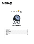
1
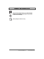
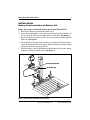
Synergy TRU-Balance BASIC OPERATION TRU-Balance 2INSTRUCTIONS Power2 RePower Tilt cline Removable Battery Pack ACN# 088 609 661 Basic Operation Instructions SAFETY GUIDELINES 2 WARNING! A Silver Star Provider or a qualified technician must perform the initial setup of this product and must perform all of the instructions in this manual. The symbols below are used throughout this owner's manual and on the product to identify warnings and important information. It is very important for you to read them and understand them completely. WARNING! Indicates a potentially hazardous condition/ situation. Failure to follow designated procedures can cause either personal injury, component damage, or malfunction. On the product, this icon is represented as a black symbol on a yellow triangle with a black border. MANDATORY! These actions should be performed as specified. Failure to perform mandatory actions can cause personal injury and/or equipment damage. On the product, this icon is represented as a white symbol on a blue dot with a white border. PROHIBITED! These actions are prohibited. These actions should not be performed at any time or in any circumstances. Performing a prohibited action can cause personal injury and/or equipment damage. On the product, this icon is represented as a black symbol with a red circle and a red slash. NOTE: These instructions are compiled from the latest specifications and product information available at the time of publication. We reserve the right to make changes as they become necessary. Any changes to our products may cause slight variations between the illustrations and explanations in this manual and the product you have purchased. The latest/current version of this manual is available on our website. 088 609 661 Copyright © 2008 Pride Mobility Products Corporation INFMANU3630/Rev C/March 2008 Removable Battery Pack www.silverstarmobility.com TABLE OF CONTENTS Basic Operation Instructions 3 LABEL INFORMATION ................................................................. 4 INTRODUCTION ............................................................................ 6 INSTALLATION ............................................................................. 7 BATTERY PACK INSTALLATION TO EXTERIOR LIFT .................. 7 BATTERY PACK INSTALLATION TO BACKPACKER SERIES LIFTS ............................................................................................. 8 BATTERY PACK INSTALLATION TO SILVERBOOM ..................... 8 BATTERY CHARGING ................................................................ 10 IN HOUSE DOCKING STATION CHARGING .............................. 11 BACKPACKER SERIES/SILVERBOOM BATTERY PACK CHARGING .................................................................................. 12 MOBILITY PRODUCT BATTERY CHARGING ............................. 13 BATTERY CHARGER LEDS ........................................................13 BATTERY REPLACEMENT ......................................................... 14 TROUBLESHOOTING .................................................................15 CHARGER SPECIFICATIONS .................................................... 17 www.silverstarmobility.com Removable Battery Pack 4 Basic Operation Instructions LABEL INFORMATION PRODUCT SAFETY SYMBOLS The symbols below are used on the product to identify warnings, mandatory actions, and prohibited actions. It is very important for you to read and understand them completely. Read and follow the information in the owner’s manual. Avoid exposure to rain, snow, ice, salt, or standing water whenever possible. Maintain and store in a clean and dry condition. Contact with tools can cause electrical shock. Do not allow unsupervised children to play near the mobility product while the batteries are charging. Do not expose to open flame. Explosive conditions exist! Corrosive chemicals contained in battery. Contains Lead. Wear safety goggles. Always replace the battery with the exact same type, chemistry, and amp-hour (Ah) capacity. Refer to the specifications table in this manual for recommended type and capacities. Removable Battery Pack www.silverstarmobility.com LABEL INFORMATION Basic Operation Instructions 5 Disposal and recycling-Contact your authorized Pride Provider for information on proper disposal of your Pride product and its packaging. Battery charger for indoor use only. www.silverstarmobility.com Removable Battery Pack 6 Basic Operation Instructions INTRODUCTION WELCOME to Silver Star, a division of Pride Mobility Products Corporation (Pride). The product you have purchased combines state-of-the-art components with safety, comfort, and styling in mind. We are confident that the design features will provide you with the conveniences you expect during your daily activities. Understanding how to safely use and care for this product should bring you years of trouble-free operation and service. Read and follow all instructions, warnings, and notes in this manual and all other accompanying literature before attempting to use this product for the first time. In addition, your safety depends upon you, as well as your provider, caretaker, or healthcare professional in using good judgement. This manual is to be used in addition to the owner’s manual that came with your lift. If there is any information in this manual which you do not understand, or if you require additional assistance for setup or operation, please contact your Silver Star Provider. Failure to follow the instructions, warnings, and notes in this manual and those located on your Pride product can result in personal injury and/or equipment damage and will void Pride’s product warranty. NOTE: If you ever lose or misplace your product registration card or your copy of this manual, contact us and we will be glad to send you a new one immediately. My Silver Star Provider Is: Name:_______________________________________________________ Address:_____________________________________________________ Phone Number:________________________________________________ Purchase Date:________________________________________________ Removable Battery Pack www.silverstarmobility.com Basic Operation Instructions 7 INSTALLATION Battery Pack Installation to Exterior Lift Follow these steps to install the battery pack to the Exterior Lift: 1. Remove the battery pack from the battery base. 2. Align the mounting holes in the battery pack base bracket with those in the accessory bracket located under the key switch tube. See figure 1. 3. Secure the battery pack base to the accessory bracket with the supplied hardware. See figure 1. 4. Insert the battery into the battery pack base, making sure that the connector on the bottom of the battery aligns and fully connects with the mating connector inside the battery pack base. 5. Plug the battery cord on the bottom of the battery pack into the mating connector running from the motor. See figure 1. BATTERY PACK BRACKET KEY SWITCH TUBE Figure 1. Battery Pack Installation to Exterior Lift www.silverstarmobility.com Removable Battery Pack 8 Basic Operation Instructions Battery Pack Installation to Backpacker Series Lifts Follow these steps to install the battery pack to a Backpacker Series Lift: 1. Remove the rubber caps and BATTERY PACK nuts from the protruding bolts on the side of the lift motor housing. See figure 2. LIFT MOTOR 2. Remove the spacer bar. See figHOUSING ure 2. 3. Mount the battery pack base onto the protruding bolts and secure into position with the nuts removed earlier. See figure 2. 4. Insert the battery pack into the battery pack base, making sure that the connector on the bottom of the battery pack aligns and fully connects with the mating connector inside the BATTERY PACK BASE battery pack base. SPACER BAR NUTS 5. Connect the male connector of BOLTS the battery harness to the female connector at the base of Figure 2. Battery Pack Installation the Backpacker. 6. Secure the battery harness to the other cables with wire ties. Battery Pack Installation to SilverBoom The base of the battery pack has 4 mounting holes (1 at each corner) for mounting the base permanently to a vehicle. Install the base in a location where it will not interfere with lift operation and is in close proximity to an auxiliary outlet or cigarette lighter outlet. WARNING! Before drilling the mounting holes in your vehicle, make absolutely certain through a visual inspection that there are no obstructions in the path of the drill bit, such as the fuel tank, exhaust pipes, or electrical wires. Removable Battery Pack www.silverstarmobility.com Basic Operation Instructions 9 PROHIBITED! Do not mount the battery pack in an area where it will be affected by moisture or dirt. Follow these steps to install the battery pack to the SilverBoom: 1. Determine a location to mount the battery pack to the vehicle. See figure 3. 2. Inspect the undercarriage of the vehicle (where the battery pack is located) for obstructions that may hinder the installation of the mounting screws that secure the base to the vehicle (e.g., electrical wiring, the gas tank, bumper mounts, or exhaust pipes). 3. Mark the location of the mounting holes, then drill pilot holes, which should be smaller than the diameter of the mounting screws. 4. Secure the case to the vehicle using the supplied hardware. 5. Plug the harness from the battery pack into the mating harness extending from the lift. See figure 3A. WARNING! A battery pack that is not secured properly to the vehicle can become a hazard while driving. MOUNTING SCREWS BATTERY HARNESS Figure 3. Battery Pack Installation Figure 3A. Harness Connections www.silverstarmobility.com Removable Battery Pack 10 Basic Operation Instructions BATTERY CHARGING Batteries may encounter temperature extremes that can influence their performance. Extreme heat diminishes the charge on the battery; extreme cold slows the available power and extends the time needed to recharge the battery. Keep the batteries fully charged whenever possible and protect the batteries from extreme heat or cold. WARNING! Always protect the batteries from freezing and never charge a frozen battery. Explosive conditions exist! Corrosive chemicals contained in battery. Use only AGM or Gel-Cell batteries to reduce the risk of leakage or explosive conditions. Removal of grounding prong can create electrical hazard. If necessary, properly install an approved 3-pronged adapter to an electrical outlet having 2-pronged plug access. Do not connect an extension cord to the AC/DC converter or the battery charger. Do not allow unsupervised children to play near the mobility product while the batteries are charging. Do not expose to open flame. Avoid exposure to rain, snow, ice, salt, or standing water whenever possible. Maintain and store in a clean and dry condition. Battery charger for indoor use only. Removable Battery Pack www.silverstarmobility.com Basic Operation Instructions 11 In House Docking Station Charging Follow these steps to charge the battery pack with the In House Docking Station: 1. Remove the battery pack from the battery pack base. 2. Place the charger base near a standard electrical outlet. See figure 4. 3. Connect the charger harness to the power lead extending from the charger base, then plug the 3-pronged plug into the electrical outlet. 4. Place the battery pack onto the charger base. 5. Monitor the LEDs on the side of the charger base for charging status. See figure 8. BATTERY PACK BATTERY CHARGER CHARGER BASE Figure 4. Battery Charging Base www.silverstarmobility.com Removable Battery Pack 12 Basic Operation Instructions Backpacker Series/SilverBoom Battery Pack Charging The battery pack used on the Backpacker Series and SilverBoom is a self-contained unit, which includes 1 battery and an internal battery charger. The battery pack charger is designed to charge the lift battery and those of a mobility product, switching between the 12-volt lift battery and the 24-volt mobility product batteries, depending on which battery is in need of a charge. (The lift battery receives priority when charging.) NOTE: The charger will normally charge the battery pack first, then switch to the mobility product charging output. NOTE: Charging switches automatically to the mobility product when it is plugged into the charger. The mobility product will be charged for one hour before switching back to top off the lift battery. During charging, if the vehicle engine is shut off, an automatic charge shut-off timer (lasting three hours) will start. If the vehicle remains off, and the vehicle’s battery is in good condition, the charger will continue to charge the lift and mobility product batteries for three hours then enter sleep mode. If the charger detects that the vehicle battery is getting too low, the charger will enter sleep mode before three hours. Charging will restart when the vehicle engine is started. Disconnecting then reconnecting the 24-volt mobility product will also restart charging and will reset the three-hour timer. If the auxiliary power outlet or cigarette lighter outlet is switched on and off with the ignition key, then charging will only take place when the ignition key is in a power-on position. The charger is powered by plugging it into one of the vehicle’s auxiliary outlets or cigarette lighter outlet. See figure 5. It is recommended that the charger be connected to a continuously powered auxiliary outlet or cigarette lighter outlet. Removable Battery Pack AUXILIARY OUTLET PLUG Figure 5. Auxiliary Outlet Plug www.silverstarmobility.com Basic Operation Instructions 13 Mobility Product Battery Charging The battery pack’s internal charger is capable of charging the batteries of the mobility product you are transporting. This option is only available for Backpacker Series and SilverBoom lifts. The internal battery pack is also capable of PLUG INTO charging a 24-volt mobility product AUXILIARY equipped with a compatible Neutrik OUTLET NC3MXX connector (for pin Figure 6. Charging A Mobility Device configurations, see figure 7). PIN 1 = BATTERY + To charge the mobility product’s batteries: 1. Ensure the battery pack is plugged into the vehicle’s auxiliary outlet. 2. Plug the charger cord into the off-board charger port on the mobility product. See figure 6. PIN 2 / PIN 3 JUMPERED = INHIBIT HIGH PIN 3 = BATTERY - Figure 7. Pin Configuration BATTERY CHARGER LEDs The LEDs on the side of the battery pack (see figure 8) indicate charging status. (See the table below.) Each battery has its own LED. The right LED indicates the charging status of the 12-volt lift battery. The left LED indicates the charging status of the 24-volt mobility device. 24-VOLT LED 12-VOLT LED Figure 8. Battery Pack LEDs LED Fast flashing LED Slow flashing LED LED is solid Both LEDs are off Alternately flashing LEDs Both LEDs alternately flash 3 times CONDITION Indicates charge verification (do batteries need charging?) Indicates the battery is charging Indicates the battery is charged above 95% Indicates the charger is off Indicates a fault Indicates the batteries are not connected www.silverstarmobility.com Removable Battery Pack 14 Basic Operation Instructions BATTERY REPLACEMENT MANDATORY! Battery posts, terminals, and related accessories contain lead and lead compounds. Wear goggles and gloves when handling batteries and wash hands after handling. WARNING! Always replace the battery with the exact same type, chemistry, and amp-hour (Ah) capacity. Refer to the specifications table in this manual for recommended type and capacities. To remove the battery from the pack (see figure 9): 1. Remove the battery pack from the base. 2. Remove the 6 screws from the bottom of the pack. BATTERY LEADS 3. Separate the pack halves. 4. Disconnect the battery leads from the battery terminals and remove the battery. 5. Put a new battery into the battery pack. 6. Connect the battery leads: red SCREW wire to the positive terminal (+) and black wire to the negative terminal (-). 7. Put the pack halves back together, reinstall the screws, and tighten. 8. Reinstall the battery pack to the Figure 9. Battery Replacement battery pack base. Removable Battery Pack www.silverstarmobility.com Basic Operation Instructions 15 TROUBLESHOOTING Any electromechanical device occasionally requires some troubleshooting. However, most of the problems that may arise can usually be solved with a bit of thought and common sense. Many of these problems occur because the battery is not fully charged or because the battery is worn down and can no longer hold a charge. What if the battery will not charge? Fully insert the appropriate ends of the charger cord into their ports. Ensure the battery pack is inserted properly into the charger pack. Check the fuses located on the bottom of the battery pack. Check the fuse located in the auxiliary outlet plug. In the event the batteries do not charge when using an auxiliary outlet: 1. Insert the auxiliary outlet plug into the auxiliary power outlet or cigarette lighter outlet. 2. If the LED on the auxiliary outlet plug does not light up, change its fuse. To change the fuse in the auxiliary outlet plug: 1. Twist the end of the auxiliary outlet plug until it seperates from the primary outlet plug. 2. Remove the end of the cap, taking care to retain the silver charging connector. 3. Remove the fuse by pulling it out of its slot. 4. Examine the fuse to be sure it is blown. See figures 10 and 11. 5. Insert a new fuse of the proper rating. 6. With the silver charging connector in place, twist the end of the cap until it is secure. Figure 10. Working Fuse Figure 11. Blown Fuse (Replace) www.silverstarmobility.com Removable Battery Pack 16 Basic Operation Instructions In the event the battery pack’s fuse should cease to work: 1. Remove the fuse by pulling it out of its slot. The fuses are located on the underside of the battery pack. 2. Examine the fuse to be sure it is blown. See figures 12 and 13. 3. Insert a new fuse of the proper rating. Figure 12. Working Fuse Figure 13. Blown Fuse (Replace) WARNING! The replacement fuses must exactly match the rating of the old fuses. Failure to use properly rated fuses may cause damage to the electrical system. Removable Battery Pack www.silverstarmobility.com Basic Operation Instructions 17 CHARGER SPECIFICATIONS LED Operating Vehicle Voltage Operating Input Voltage Input Current (RMS): Input Fuse Output Fuse (One For Each Battery) Car Voltage minimum for auto shut-off Maximum Charging Current Onboard LEDs: (2) One For Each Battery CONDITION 12.1V - 15.5V DC (Measured at car battery) 11.5V - 15.5V DC (Measured at charger) 5.8 Amps maximum 3AG 7-Amp or ATC 7.5-Amp (Fast Blow) 4-amp (Fast Blow) 12.1-Volts 2.5-Amps Color: green www.silverstarmobility.com Removable Battery Pack 18 Removable Battery Pack Basic Operation Instructions www.silverstarmobility.com Basic Operation Instructions www.silverstarmobility.com 19 Removable Battery Pack Pride Mobility Products Corporation 182 Susquehanna Avenue Exeter, PA 18643-2694 USA Pride Mobility Products Company 380 Vansickle Road Unit 350 St. Catharines, Ontario L2R 6P7 Canada www.pridemobility.com www.silverstarmobility.com *INFMANU3630*