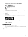
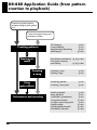
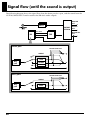
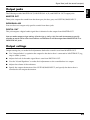
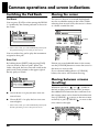
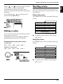
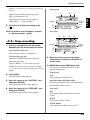
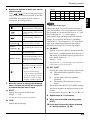
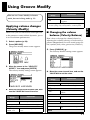
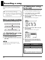
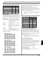
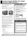
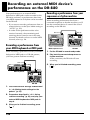
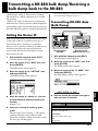
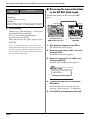
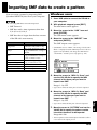
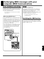
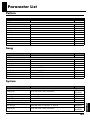
1
Owner’s Manual
Thank you, and congratulations on your choice of the BOSS DR-880 Dr. Rhythm.
Before using this unit, carefully read the sections entitled:
• USING THE UNIT SAFELY (page 2–3)
• IMPORTANT NOTES (page 4–5)
These sections provide important information concerning the proper operation of the unit.
Additionally, in order to feel assured that you have gained a good grasp of every feature provided by your new unit, the owner’s manual should be read in its entirety. The manual should
be saved and kept on hand as a convenient reference.
■ Printing Conventions in This Manual
• Text or numerals enclosed in square brackets [ ] indicate buttons.
[EFFECT]
EFFECT button
[PATTERN]
PATTERN button
• Reference such as (p. **) indicate pages in this manual to which you can refer.
Copyright © 2004 BOSS CORPORATION
All rights reserved. No part of this publication may be reproduced in any form without the written permission
of BOSS CORPORATION.
G601738001
USING THE UNIT SAFELY
The
symbol alerts the user to important instructions
or warnings.The specific meaning of the symbol is
determined by the design contained within the
triangle. In the case of the symbol at left, it is used for
general cautions, warnings, or alerts to danger.
Used for instructions intended to alert
the user to the risk of death or severe
injury should the unit be used
improperly.
Used for instructions intended to alert
the user to the risk of injury or material
damage should the unit be used
improperly.
* Material damage refers
other adverse effects
respect to the home
furnishings, as well
animals or pets.
The
symbol alerts the user to items that must never
be carried out (are forbidden). The specific thing that
must not be done is indicated by the design contained
within the circle. In the case of the symbol at left, it
means that the unit must never be disassembled.
to damage or
caused with
and all its
to domestic
The ● symbol alerts the user to things that must be
carried out. The specific thing that must be done is
indicated by the design contained within the circle. In
the case of the symbol at left, it means that the powercord plug must be unplugged from the outlet.
For the U.K.
IMPORTANT: THE WIRES IN THIS MAINS LEAD ARE COLOURED IN ACCORDANCE WITH THE FOLLOWING CODE.
BLUE:
NEUTRAL
BROWN: LIVE
As the colours of the wires in the mains lead of this apparatus may not correspond with the coloured markings identifying
the terminals in your plug, proceed as follows:
The wire which is coloured BLUE must be connected to the terminal which is marked with the letter N or coloured BLACK.
The wire which is coloured BROWN must be connected to the terminal which is marked with the letter L or coloured RED.
Under no circumstances must either of the above wires be connected to the earth terminal of a three pin plug.
For EU Countries
This product complies with the requirements of European Directive 89/336/EEC.
001
008c
• Before using this unit, make sure to
read the instructions below, and the
Owner’s Manual.
• Be sure to use only the AC adaptor
supplied with the unit. Also, make
sure the line voltage at the installation
matches the input voltage specified on
the AC adaptor’s body. Other AC
adaptors may use a different polarity,
or be designed for a different voltage,
so their use could result in damage,
malfunction, or electric shock.
..................................................................................................
002c
• Do not open (or modify in any way)
the unit or its AC adaptor.
..................................................................................................
003
• Do not attempt to repair the unit, or
replace parts within it (except when
this manual provides specific instructions directing you to do so). Refer all
servicing to your retailer, the nearest
Roland Service Center, or an authorized Roland distributor, as listed on
the “Information” sheet.
..................................................................................................
004
• Never use or store the unit in places
that are:
• Subject to temperature extremes
(e.g., direct sunlight in an enclosed
vehicle, near a heating duct, on top
of heat-generating equipment); or
are
• Damp (e.g., baths, washrooms, on
wet floors); or are
• Humid; or are
• Exposed to rain; or are
• Dusty; or are
• Subject to high levels of vibration.
..................................................................................................
007
• Make sure you always have the unit
placed so it is level and sure to remain
stable. Never place it on stands that
could wobble, or on inclined surfaces.
..................................................................................................
2
.................................................................................................
009
• Do not excessively twist or bend the
power cord, nor place heavy objects
on it. Doing so can damage the cord,
producing severed elements and short
circuits. Damaged cords are fire and
shock hazards!
.................................................................................................
010
• This unit, either alone or in combination with an amplifier and
headphones or speakers, may be
capable of producing sound levels that
could cause permanent hearing loss.
Do not operate for a long period of
time at a high volume level, or at a
level that is uncomfortable. If you
experience any hearing loss or ringing
in the ears, you should immediately stop
using the unit, and consult an audiologist.
For the USA
FEDERAL COMMUNICATIONS COMMISSION
RADIO FREQUENCY INTERFERENCE STATEMENT
This equipment has been tested and found to comply with the limits for a Class B digital device, pursuant to Part 15 of the
FCC Rules. These limits are designed to provide reasonable protection against harmful interference in a residential
installation. This equipment generates, uses, and can radiate radio frequency energy and, if not installed and used in
accordance with the instructions, may cause harmful interference to radio communications. However, there is no guarantee
that interference will not occur in a particular installation. If this equipment does cause harmful interference to radio or
television reception, which can be determined by turning the equipment off and on, the user is encouraged to try to correct the
interference by one or more of the following measures:
– Reorient or relocate the receiving antenna.
– Increase the separation between the equipment and receiver.
– Connect the equipment into an outlet on a circuit different from that to which the receiver is connected.
– Consult the dealer or an experienced radio/TV technician for help.
This device complies with Part 15 of the FCC Rules. Operation is subject to the following two conditions:
(1) This device may not cause harmful interference, and
(2) This device must accept any interference received, including interference that may cause undesired operation.
Unauthorized changes or modification to this system can void the users authority to operate this equipment.
This equipment requires shielded interface cables in order to meet FCC class B Limit.
For Canada
NOTICE
This Class B digital apparatus meets all requirements of the Canadian Interference-Causing Equipment Regulations.
AVIS
Cet appareil numérique de la classe B respecte toutes les exigences du Règlement sur le matériel brouilleur du Canada.
For the USA
.................................................................................................
DECLARATION OF CONFORMITY
Compliance Information Statement
011
• Do not allow any objects (e.g.,
flammable material, coins, pins); or
liquids of any kind (water, soft drinks,
etc.) to penetrate the unit.
.................................................................................................
Model Name :
Type of Equipment :
Responsible Party :
Address :
Telephone :
DR-880
Dr. Rhythm
Roland Corporation U.S.
5100 S.Eastern Avenue, Los Angeles, CA 90040-2938
(323) 890-3700
012b
101b
• Immediately turn the power off,
remove the AC adaptor from the
outlet, and request servicing by your
retailer, the nearest Roland Service
Center, or an authorized Roland
distributor, as listed on the “Information”
sheet when:
• The AC adaptor, the power-supply cord,
or the plug has been damaged; or
• If smoke or unusual odor occurs
• Objects have fallen into, or liquid has been
spilled onto the unit; or
• The unit has been exposed to rain (or
otherwise has become wet); or
• The unit does not appear to operate
normally or exhibits a marked change in
performance.
• The unit and the AC adaptor should
be located so their location or position
does not interfere with their proper
ventilation.
..................................................................................................
013
• In households with small children, an
adult should provide supervision until
the child is capable of following all the
rules essential for the safe operation of
the unit.
..................................................................................................
014
• Protect the unit from strong impact.
(Do not drop it!)
..................................................................................................
015
• Do not force the unit’s power-supply
cord to share an outlet with an unreasonable number of other devices. Be
especially careful when using
extension cords—the total power used
by all devices you have connected to
the extension cord’s outlet must never
exceed the power rating (watts/amperes) for
the extension cord. Excessive loads can cause
the insulation on the cord to heat up and
eventually melt through.
..................................................................................................
016
• Before using the unit in a foreign
country, consult with your retailer, the
nearest Roland Service Center, or an
authorized Roland distributor, as listed on the
“Information” sheet.
..................................................................................................
023
• DO NOT play a CD-ROM disc on a
conventional audio CD player. The
resulting sound may be of a level that
could cause permanent hearing loss.
Damage to speakers or other system
components may result.
..................................................................................................
102c
• Always grasp only the plug on the AC
adaptor cord when plugging into, or
unplugging from, an outlet or this
unit.
..................................................................................................
103b
• At regular intervals, you should
unplug the AC adaptor and clean it by
using a dry cloth to wipe all dust and
other accumulations away from its
prongs. Also, disconnect the power
plug from the power outlet whenever
the unit is to remain unused for an extended
period of time. Any accumulation of dust
between the power plug and the power outlet
can result in poor insulation and lead to fire.
..................................................................................................
104
• Try to prevent cords and cables from
becoming entangled. Also, all cords
and cables should be placed so they
are out of the reach of children.
..................................................................................................
106
• Never climb on top of, nor place heavy
objects on the unit.
..................................................................................................
107c
• Never handle the AC adaptor or its
plugs with wet hands when plugging
into, or unplugging from, an outlet or
this unit.
..................................................................................................
108b
• Before moving the unit, disconnect the
AC adaptor and all cords coming from
external devices.
..................................................................................................
109b
• Before cleaning the unit, turn off the
power and unplug the AC adaptor
from the outlet.
..................................................................................................
110b
• Whenever you suspect the possibility
of lightning in your area, disconnect
the AC adaptor from the outlet.
..................................................................................................
..................................................................................................
3
IMPORTANT NOTES
291a
In addition to the items listed under “USING THE UNIT SAFELY” on page 2–3, please read and
observe the following:
Power Supply
301
• Do not connect this unit to same electrical
outlet that is being used by an electrical
appliance that is controlled by an inverter
(such as a refrigerator, washing machine,
microwave oven, or air conditioner), or that
contains a motor. Depending on the way in
which the electrical appliance is used, power
supply noise may cause this unit to
malfunction or may produce audible noise. If
it is not practical to use a separate electrical
outlet, connect a power supply noise filter
between this unit and the electrical outlet.
302
• The AC adaptor will begin to generate heat
after long hours of consecutive use. This is
normal, and is not a cause for concern.
307
• Before connecting this unit to other devices,
turn off the power to all units. This will help
prevent malfunctions and/or damage to
speakers or other devices.
Placement
351
354a
• Do not expose the unit to direct sunlight,
place it near devices that radiate heat, leave it
inside an enclosed vehicle, or otherwise
subject it to temperature extremes. Excessive
heat can deform or discolor the unit.
355b
• When moved from one location to another
where the temperature and/or humidity is
very different, water droplets (condensation)
may form inside the unit. Damage or
malfunction may result if you attempt to use
the unit in this condition. Therefore, before
using the unit, you must allow it to stand for
several hours, until the condensation has
completely evaporated.
Maintenance
401a
• For everyday cleaning wipe the unit with a
soft, dry cloth or one that has been slightly
dampened with water. To remove stubborn
dirt, use a cloth impregnated with a mild,
non-abrasive detergent. Afterwards, be sure
to wipe the unit thoroughly with a soft, dry
cloth.
• Using the unit near power amplifiers (or
other equipment containing large power
transformers) may induce hum. To alleviate
the problem, change the orientation of this
unit; or move it farther away from the source
of interference.
402
352a
452
• This device may interfere with radio and
television reception. Do not use this device in
the vicinity of such receivers.
352b
• Noise may be produced if wireless communications devices, such as cell phones, are
operated in the vicinity of this unit. Such
noise could occur when receiving or initiating
a call, or while conversing. Should you
experience such problems, you should
relocate such wireless devices so they are at a
greater distance from this unit, or switch
them off.
4
• Never use benzine, thinners, alcohol or
solvents of any kind, to avoid the possibility
of discoloration and/or deformation.
Repairs and Data
• Please be aware that all data contained in the
unit’s memory may be lost when the unit is
sent for repairs. Important data should
always be backed up in another MIDI device
(e.g., a sequencer), computer, or written down
on paper (when possible). During repairs, due
care is taken to avoid the loss of data.
However, in certain cases (such as when
circuitry related to memory itself is out of
order), we regret that it may not be possible to
restore the data, and Roland assumes no
liability concerning such loss of data.
IMPORTANT NOTES
Additional Precautions
551
• Please be aware that the contents of memory
can be irretrievably lost as a result of a
malfunction, or the improper operation of the
unit. To protect yourself against the risk of
loosing important data, we recommend that
you periodically save a backup copy of
important data you have stored in the unit’s
memory in another MIDI device (e.g., a
sequencer) or computer.
552
• Unfortunately, it may be impossible to restore
the contents of data that was stored in the
unit’s memory once it has been lost. Roland
Corporation assumes no liability concerning
such loss of data.
553
• Use a reasonable amount of care when using
the unit’s buttons, sliders, or other controls;
and when using its jacks and connectors.
Rough handling can lead to malfunctions.
554
• Never strike or apply strong pressure to the
display.
556
• When connecting / disconnecting all cables,
grasp the connector itself—never pull on the
cable. This way you will avoid causing shorts,
or damage to the cable’s internal elements.
558a
• To avoid disturbing your neighbors, try to
keep the unit’s volume at reasonable levels.
You may prefer to use headphones, so you do
not need to be concerned about those around
you (especially when it is late at night).
559a
561
• Use only the specified expression pedal (EV5; sold separately). By connecting any other
expression pedals, you risk causing
malfunction and/or damage to the unit.
562
• Use a cable from Roland to make the
connection. If using some other make of
connection cable, please note the following
precautions.
• Some connection cables contain resistors.
Do not use cables that incorporate resistors
for connecting to this unit. The use of such
cables can cause the sound level to be
extremely low, or impossible to hear. For
information on cable specifications, contact
the manufacturer of the cable.
985
• The explanations in this manual include illustrations that depict what should typically be
shown by the display. Note, however, that
your unit may incorporate a newer, enhanced
version of the system (e.g., includes newer
sounds), so what you actually see in the
display may not always match what appears
in the manual.
Handling CD-ROMs
801
• Avoid touching or scratching the shiny
underside (encoded surface) of the disc.
Damaged or dirty CD-ROM discs may not be
read properly. Keep your discs clean using a
commercially available CD cleaner.
• When you need to transport the unit, package
it in the box (including padding) that it came
in, if possible. Otherwise, you will need to use
equivalent packaging materials.
....................................................................................................................................................................................
204
* Microsoft and Windows are registered trademarks of Microsoft Corporation.
206e
* The screen shots in this document are used in compliance with the guidelines of the Microsoft Corporation.
206j
* Windows® is known officially as: “Microsoft® Windows® operating system.”
207
* Apple and Macintosh are registered trademark of Apple Computer, Inc.
209
* Mac OS is a trademark of Apple Computer, Inc.
220
* All product names mentioned in this document are trademarks or registered trademarks of their respective owners.
231
* OMS is a registered trademark of Opcode Systems, Inc.
232
*
FreeMIDI is a trademark of Mark of the Unicorn, Inc.
5
Contents
USING THE UNIT SAFELY ..................................................................... 2
IMPORTANT NOTES............................................................................... 4
Main features ........................................................................................ 11
Front and Rear Panels ......................................................................... 13
Front Panel................................................................................................................. 13
Rear Panel .................................................................................................................. 16
Before you begin playing..................................................................... 17
Making connections.................................................................................................. 17
Turning the power on/off ....................................................................................... 18
Adjusting the display contrast................................................................................ 20
Quick Start..........................................................21
Listening to the demo song................................................................. 22
Using the key pads to play sounds .................................................... 23
Playing Different Sounds (Switching Pad Banks)................................................ 23
Playing the patterns ............................................................................. 24
Selecting and playing patterns................................................................................ 24
Changing the tempo ................................................................................................. 26
Changing the playback key ..................................................................................... 27
Playing a Pattern Using a Different Sound (Switching Kits).............................. 28
Using the TSC function to modify the tone and ambience................................. 30
Playing your guitar/bass along with patterns.................................... 32
Using the special guitar/bass effects ..................................................................... 33
Chapter 1 An overview of the DR-880 .................35
DR-880 Application Guide (from pattern creation to playback) ....... 36
Patterns and Songs.............................................................................. 38
Patterns....................................................................................................................... 38
Songs........................................................................................................................... 39
About kits................................................................................................................... 40
Pad bank..................................................................................................................... 41
About TSC (Total Sound Control).......................................................................... 42
Guitar/Bass section.............................................................................. 43
Guitar Effects ............................................................................................................. 43
Signal flow (until the sound is output) ............................................... 44
Output jacks............................................................................................................... 45
Output settings.......................................................................................................... 45
Common operations and screen indications..................................... 46
Switching the Pad Bank ........................................................................................... 46
Moving the cursor..................................................................................................... 46
Moving between screens (Scrolling) ...................................................................... 46
6
Contents
Editing a value .......................................................................................................... 47
The Play screen.......................................................................................................... 47
Chapter 2 Patterns (playing, recording, editing) ........49
Playing a pattern................................................................................... 50
Changing the tempo ................................................................................................. 50
Changing the playback key ..................................................................................... 50
Switching the display ............................................................................................... 51
Recording a pattern.............................................................................. 52
Realtime recording and Step recording................................................................. 52
Before you begin recording ..................................................................................... 52
<1> Selecting the user pattern you want to record.............................................. 52
<2> Making basic settings for the pattern............................................................. 53
<3-1> Using realtime recording.............................................................................. 54
<3-2> Step-recording................................................................................................ 55
<4> Recording a chord progression....................................................................... 58
<5> Recording a fill-in ............................................................................................. 60
Pattern editing (Pattern Edit)............................................................... 61
Copying a portion of a pattern (Copy Measure).................................................. 61
Inserting blank measures into a pattern (Insert Measure).................................. 62
Erasing a portion of a pattern (Erase) .................................................................... 63
Deleting unwanted measures (Delete Measure) .................................................. 64
Saving a pattern.................................................................................... 65
Naming a pattern (Pattern Name).......................................................................... 65
Writing your pattern ................................................................................................ 65
Copying/Erasing a pattern................................................................... 66
Copying a pattern ..................................................................................................... 66
Erasing a pattern ....................................................................................................... 66
Chapter 3 EZ Compose/Groove Modify ...............67
Using EZ Compose............................................................................... 68
Creating a pattern ..................................................................................................... 68
Adding a chord progression ................................................................................... 69
Adding a fill-in .......................................................................................................... 70
Using Groove Modify ........................................................................... 71
Applying volume changes (Velocity Modify) ...................................................... 71
Adding ghost notes .................................................................................................. 72
Creating a shuffle rhythm ....................................................................................... 73
7
Contents
Chapter 4 Song (record/edit/play) ......................75
Recording a song ................................................................................. 76
Before you begin recording ..................................................................................... 76
<1> Selecting the user song you want to record .................................................. 76
<2> Making basic settings for the song ................................................................. 76
<3> Step-recording your song ................................................................................ 77
Saving your song ................................................................................. 79
Naming your song (Song Name)............................................................................ 79
Writing your song..................................................................................................... 79
Copying/Clearing a song ..................................................................... 80
Copying a song ......................................................................................................... 80
Clearing (erasing) a song ......................................................................................... 80
Playing a song ...................................................................................... 81
Changing the tempo ................................................................................................. 81
Changing the playback key ..................................................................................... 82
Looping the playback in a specified region .......................................................... 82
Switching the display ............................................................................................... 83
Chapter 5 Playing your guitar/bass ....................85
Using effects ......................................................................................... 86
Switching effect patches........................................................................................... 86
Editing an effect patch (Patch Edit)........................................................................ 86
Saving/Copying an Effect patch.......................................................... 88
Naming an effect patch ............................................................................................ 88
Writing an effect patch............................................................................................. 88
Copying an effect patch ........................................................................................... 89
Using the Tuner/Expression pedal ..................................................... 90
Tuning your guitar/bass ......................................................................................... 90
Using an expression pedal as a volume pedal ..................................................... 91
Guitar effects parameter list................................................................ 92
GTR MULTI (Guitar multi) ..................................................................................... 92
BASS MULTI ............................................................................................................. 92
ACO (Acoustic) MULTI ........................................................................................... 92
Description of the effects ......................................................................................... 93
Chapter 6 Editing the TSC settings........................99
TSC patch editing ............................................................................... 100
Edit procedure......................................................................................................... 100
Saving/Copying a TSC patch............................................................. 103
Naming a TSC patch............................................................................................... 103
Writing a TSC patch ............................................................................................... 103
Copying a TSC patch.............................................................................................. 104
8
Contents
Chapter 7 Creating an original kit (Kit Edit) .......105
Editing a kit ......................................................................................... 106
Selecting the kit you want to edit ......................................................................... 106
Editing the Drum part............................................................................................ 106
Editing the Bass part............................................................................................... 110
Saving/Copying a kit .......................................................................... 113
Naming a kit ............................................................................................................ 113
Writing a kit............................................................................................................. 113
Copying a kit ........................................................................................................... 114
Chapter 8 Convenient function/System settings .......115
FAVORITE function ............................................................................ 116
Recalling the registered content ........................................................................... 116
Registering a favorite ............................................................................................. 117
Saving all current settings................................................................. 118
System settings .................................................................................. 119
Adjusting the output signal (Output Setting)..................................................... 119
Adjusting the sensitivity of the key pads (Pad Sens) ........................................ 120
Tuning the bass part ............................................................................................... 120
Using foot switches................................................................................................. 121
Adding a count-in................................................................................................... 123
Using the same kit/TSC patch for playing all patterns and songs ................. 123
Specifying the pattern at power-on...................................................................... 124
Chapter 9 Using MIDI ........................................125
Playing the DR-880 from an external MIDI device/
Playing an external MIDI device from the DR-880 ........................... 126
Setting the MIDI channel ....................................................................................... 126
Setting the Volume receive switch ....................................................................... 126
Synchronizing the DR-880
with a digital recorder or MIDI sequencer ........................................ 128
Sync Mode setting................................................................................................... 128
Recording an external MIDI device’s performance on the DR-880 ........... 130
Recording a performance from your MIDI keyboard or MIDI pads .............. 130
Recording a performance from your sequencer or rhythm machine.............. 130
Transmitting a DR-880 bulk dump/
Receiving a bulk dump back to the DR-880 ..................................... 131
Setting the Device ID.............................................................................................. 131
Transmitting DR-880 data (Bulk Dump) ............................................................. 131
9
Contents
Chapter 10 Using USB .......................................133
Before you use USB ........................................................................... 134
Supported operating systems ............................................................................... 134
Notes on Using USB ............................................................................................... 134
Switching the USB function................................................................................... 134
Importing SMF data to create a pattern............................................ 135
Windows users........................................................................................................ 135
Macintosh users ...................................................................................................... 137
Backing up the DR-880’s data ........................................................... 138
Windows users........................................................................................................ 138
Macintosh users ...................................................................................................... 139
Reading backup data
back into the DR-880 from the computer (Recover)........................ 141
Windows users........................................................................................................ 141
Macintosh users ...................................................................................................... 142
Exchanging MIDI messages
with your computer (MIDI Communication) ..................................... 143
Driver installation and settings ............................................................................ 143
Switching the USB function................................................................................... 143
Appendices .......................................................145
Restoring the factory settings (Factory Reset) ............................... 146
Troubleshooting ................................................................................. 147
Message List ....................................................................................... 148
Parameter List..................................................................................... 149
Preset Data List .................................................................................. 151
MIDI Implementation Chart ................................................................ 160
Specifications ..................................................................................... 162
Index .................................................................................................... 163
10
Main features
■ High-quality sounds
■ Rhythm Patterns and Songs
● Cutting-edge, high-quality waves
The DR-880 contains 500 preset rhythm patterns,
and also lets you create 500 of your own original
rhythm patterns. In addition to realtime
recording or step input, you can use the EZ
Compose functions or the Groove Modify
function to create original patterns easily.
You can connect multiple rhythm patterns to
create a “Song,” and save up to one hundred
such songs that you create.
The DR-880 makes it easy for you to play
rhythm patterns using drum and bass. It
contains 440 of the latest, high-quality drum and
percussion sounds, plus 40 different bass
sounds—and you can vary the velocity to create
expressive changes in volume or tone. A
complete range of expressive potential is now at
your fingertips, allowing you to create the most
realistic of sounds, with any amount of
dynamism or subtlety you desire.
In addition to 100 preset kits, you can create and
store 100 of your own original kits.
● Use insert effects for boldly creative
sound manipulation
The drum part provides three insert effects
processors (three-band EQ and compressor).
Since you can apply effects independently to the
kick, snare, and other instruments, you can use
the effects aggressively for creative purposes.
The bass part provides a compressor and COSM
amp, giving you the realistic sound of a bass
played through an amp.
COSM (Composite Object Sound Modeling)
Composite Object Sound Modeling (COSM) is an
original sound modeling technology developed by
Roland, in which the many factors that make up
the original sound, such as the electrical circuitry,
structural characteristics, materials used, and
acoustics, are analyzed and then recombined to
reproduce that same sound.
● TSC (Total Sound Control) function
TSC is a function that adjusts the overall tonal
character and reverberation. A stereo three-band
equalizer and high-quality reverb let you create
anything from natural-sounding ambience to the
reverberation of a wide range of rooms and
halls.
TSC settings are stored as patches and can be
switched easily. In addition to twenty preset
patches, you can create and store twenty of your
own.
● EZ Compose
The EZ Compose functions make it easy to
create high-quality original patterns with a great
rhythmic feel, without having to input notes one
by one. The three EZ COMPOSE buttons on the
panel let you use these functions in combination
with each other.
[PATTERN]
This function lets you create an original rhythm
pattern simply by choosing a phrase for each
component; hi-hat, kick and snare, percussion,
and bass.
[CHORD PROGRESSION]
This function lets you add a chord progression
to the bass part simply by choosing a chord
progression template. It’s an incredibly easy way
to create a repeating chord progression or to set
up a blues progression.
[FILL IN]
A rich variety of fill patterns are provided,
ranging from light fills to fills that occupy an
entire measure. Simply choose a fill pattern and
paste it into your rhythm pattern.
● Groove Modify function
This lets you easily add “ghost notes,” which are
otherwise difficult to add when inputting notes
one at a time. You can adjust Shuffle or Velocity
to give your rhythm pattern the perfect groove.
11
Main features
■ Guitar/bass input
The DR-880 provides a guitar/bass input jack
and built-in high-quality multi-effects, including
a COSM AMP effect. You can connect your
guitar/bass directly to the DR-880 and play
along with the rhythm patterns using sounds
that are just as realistic as if you were playing
through an actual amp.
The built-in multi-effects processing provides
algorithms for electric guitar, acoustic guitar,
and bass. Settings for each effect are stored as
“patches,” and you can choose from fifty preset
patches as well as store fifty more patches with
your own edited settings. There’s also a tuner
function that let’s you tune your guitar/bass
while it’s still connected.
■ Convenient functionality
and plenty of connectors
● Large backlit display
The large custom LCD shows chord progressions,
patterns, performance information, and editing
data in an easily understood fashion.
● FAVORITE function
Frequently used patterns, songs, or effect
patches can be registered to a button for
immediate recall. This lets you play the desired
pattern/song or switch guitar effects simply by
pressing a button. Since this function lets you
use four buttons x 20 banks, you can register a
total of 80 patterns, songs, or effect patches.
● Control via foot switch
You can connect up to four foot switches (sold
separately). Even while playing your guitar or
bass, you can use your feet to control the DR880—ideal for jam sessions or on-stage
performances. When making the assignments to
the foot switches, you can choose from a wide
range of functions, including starting/stopping
playback, switching patterns, setting tap tempo,
or switching guitar effects.
You can also connect an expression pedal and
use it for pedal control of the volume, or as a
wah pedal.
12
● A wide range of output jacks
In addition to phone jacks, RCA phono jacks are
also provided for master output, making it easy
to connect the DR-880 to a wide range of
equipment including mixers, amps, and audio
equipment.
There’s also a coaxial-type digital output jack,
letting you record the DR-880’s output in digital
form directly to your digital recorder without
any loss in audio quality.
Two individual outputs are also provided. You
can use these to send only the output of a
connected guitar/bass to your amp, or to use an
external effects processor on a specific
instrumental sound.
● USB connector
When the DR-880 is connected to your computer
via the USB connector, you can load SMF data
and use it as rhythm patterns. The USB
connector can also be used as a MIDI interfacing.
● Synchronized playback with digital
recorders and MIDI sequencer
You can use MIDI to synchronize the DR-880
with digital recorders, such as those in the BR
series, or with your MIDI sequencer. The
playback from your external MIDI device can
also be recorded on the DR-880.
● Dynamics-capable key pads
The dynamics-capable key pads allow the
volume or tone to be altered depending on the
force used when tapping a pad. When recording
a pattern, variations in the force with which you
tap the pads can be recorded as the strength
(velocity) of the notes.
Front and Rear Panels
Front Panel
fig.001-010
1
2
3 11
4
5
26
27
28
7
6
8,9,10
12,13,14,15,16
17,18,19
20,21,22
23,24,25
29
31
1. GUITAR/BASS INPUT Knob
Adjusts the level of the guitar or bass
connected to the GUITAR/BASS INPUT jack.
2. PART LEVEL
30
32
6. GUITAR/BASS INPUT
You will use these buttons for a guitar or bass
you’ve connected to the GUITAR/BASS
INPUT jack.
DRUM Knob
Adjusts the volume of the drum part.
EFFECT Button
Use this button to change the guitar/bass
effect, turn it on/off, or edit the settings.
BASS Knob
Adjusts the volume of the bass part.
TUNER Button
Use this button to tune your guitar/bass.
3. MASTER VOLUME Knob
Adjusts the volume of the entire DR-880.
4. Display
Shows the current mode and settings.
5. VALUE Dial
Use this to edit the value of a setting.
7. OUTPUT SETTING Button
Use this button to adjust the output signal.
8. SONG/PATTERN Button
Switches between Song mode and Pattern
mode.
9. KIT Button
Use this button to switch kits.
13
Front and Rear Panels
fig.001-010
1
2
3 11
4
5
26
27
28
7
6
8,9,10
12,13,14,15,16
17,18,19
20,21,22
23,24,25
29
31
10. PAD Button
30
17.
Use this button to switch pad banks.
18.
19.
20.
15. EXIT Button
Use this button to exit from an edit screen.
16. ENTER Button
Use this button to finalize a selection or
confirm a value.
(Stop) Button
Stops playback of the song or pattern.
14. EDIT Button
Use this button to edit settings.
(Fast-Forward) Button
Moves the playback location forward in the
song or pattern.
13. DISPLAY Button
Use this button to switch the contents shown
in the Pattern or Song Play screen.
(Rewind) Button
Moves the playback location toward the
beginning of the song or pattern.
12. SHIFT Button
Use this button to access alternate functions
of other buttons.
(Reset) Button
Returns you to the beginning of the song or
pattern.
11. CURSOR Buttons
Use these buttons to move the cursor.
32
21.
(Play) Button
Starts playback of the song or pattern.
22. REC (Recording) Button
Press this button to record a pattern in real
time (p. 54).
23. LOOP Button
Switches loop playback (p. 82) on/off for the
song.
14
Front and Rear Panels
24. KEY Button
Use this button to change the playback key of
a song or pattern.
25. TEMPO (TAP) Button
Use this button to specify the playback tempo
of a song or pattern.
You can also set the tempo by tapping
(lightly striking) this button at regular
intervals (the Tap Tempo function).
31. PHONES (headphone) Jack
You can connect a set of headphones to this
jack.
32. GUITAR/BASS INPUT Jack
You can connect your guitar or bass to this
jack.
26. EZ COMPOSE
Press these buttons to use the EZ Compose
functions.
PATTERN Button
Use this button to easily create patterns.
CHORD PROGRESSION Button
Use this button to easily add chord
progressions.
FILL IN Button
Use this button to easily add fill-in patterns.
27. GROOVE MODIFY Button
Press this button when you want to use the
Groove Modify function.
28. TSC (Total Sound Control) Button
Use this button to switch the TSC patch on/
off, or to edit the settings. (p. 30, p. 100)
29. Key Pads
These pads play drum sounds and bass
sounds.
30. FAVORITE
You can use these buttons to register eighty
(20 banks x 4) of your favorite pattern/song
numbers or guitar effect patch numbers.
1–4 Buttons
Press one of these buttons to recall the
pattern/song or guitar effect patch that is
registered to that button.
BANK Button
You can switch favorite banks by pressing
down this button and pressing a key pad.
15
Front and Rear Panels
Rear Panel
fig.001-020
11
10
1 2 3
4
1. AC IN (AC adaptor) Jack
Connect the included BRC-series AC adaptor
to this jack.
Never connect any AC adaptor other than the BRCseries; doing so will cause malfunctions.
2. POWER Switch
This is the power switch that turns the DR880 on/off.
3. USB Connector
This connector lets you use a USB cable to
connect the DR-880 to your computer.
4. MIDI Connectors (IN/OUT)
These connectors receive (IN) and transmit
(OUT) MIDI data.
Use MIDI cables to connect them to your
MIDI sequencer or MIDI sound module.
5. DIGITAL OUT Connector
This is a coaxial-type connector that outputs
digital audio signals.
It outputs the same sound as the MASTER
OUT jacks.
Connect it to your digital recorder.
5 7 6
8
9
6. CTL 1, 2 Jack
You can connect foot switches (FS-6 or FS-5U;
sold separately) here and use them to control
various functions of the DR-880.
7. CTL 3, 4/EXP PEDAL Jack
You can connect foot switches (FS-6 or FS-5U;
sold separately) or an expression pedal
(Roland EV-5; sold separately) here and use
them to control various functions of the DR880.
8. INDIVIDUAL A, B Jacks
These jacks output only the sounds you
specify.
9. MASTER OUT Jacks R/L (MONO)
These are the audio signal output jacks. Both
phone jacks and RCA phono jacks are
provided.
If you’re using the phone jacks, connect your
equipment to the L (MONO) output if you’re
listening in monaural.
10.Cord Hook
Loop the cord from the supplied AC adaptor
around this hook. In the event that the cord
gets tugged on accidentally, this will prevent
the plug from coming out and causing the
power to fail, and will prevent excessive
strain from being placed on the AC adaptor
jack.
11. Security Slot (
SECURITY LOCK)
http://www.kensington.com/
16
Before you begin playing
Making connections
The DR-880 does not contain an amp or speakers. In order to produce sound, you’ll need to
connect an amp or audio system, or stereo headphones.
Audio cables, MIDI cables, stereo headphones, and foot switches are not included. You can
purchase them separately from your dealer.
fig.002-010
MIDI sequencer
etc.
Pad controller
etc.
Digital recorder etc.
Audio set
Computer
Monitor speakers
(Powered)
Foot switch (FS-6 etc.)
AC adaptor
(BRC-series)
Expression pedal
(Roland EV-5)
Guitar
or
Bass
Stereo headphones
Mixer, Guitar amp, etc.
To prevent malfunction and/or damage to speakers or other devices, always turn down
the volume, and turn off the power on all devices before making any connections.
17
Before you begin playing
* To prevent the inadvertent disruption of power to your unit (should the plug be pulled out
accidentally), and to avoid applying undue stress to the AC adaptor jack, anchor the power cord
using the cord hook, as shown in the illustration.
fig.002-020
1
Before you start making connections, check the following:
• Have you turned down the volume controls of the DR-880 and the connected amp or
other equipment?
• Have you turned off the power of the DR-880 and the connected amp or other
equipment?
2
Connect your amp or audio system (or headphones) as shown in the diagram.
We recommend that you use a stereo playback system in order to take full advantage of the
DR-880’s capabilities.
If you are using the DR-880 with a monaural playback system, connect it to the OUTPUT L
(MONO) jack.
Turning the power on/off
■ Turning the power on
Once the connections have been completed (p. 17), turn on power to your various devices
in the order specified. By turning on devices in the wrong order, you risk causing
malfunction and/or damage to speakers and other devices.
1
Before you turn on the power, check the following:
• Is the DR-880 correctly connected to your other equipment?
• Have you turned down the volume of the DR-880 and your connected amp or playback
system?
2
fig.002-030
18
Turn on the POWER switch located on the DR-880’s rear panel.
Before you begin playing
The following appears in the display, and the unit switches to performance mode.
The screen that appears at that point is called the “Pattern Play screen.”
fig.002-031d
This unit is equipped with a protection circuit. A brief interval (a few seconds) after power
up is required before the unit will operate normally.
3
4
Turn on the power of your amp and other connected equipment.
Press [
].
Playback will begin.
While listening to the playback, turn the MASTER VOLUME knob and PART LEVEL
(DRUM, BASS) knobs to adjust the DR-880’s volume.
fig.002-040
Adjust the volume appropriately on your connected amp or playback system.
5
Press [
] to stop playback.
■ Turning the power off
1
Before you turn off the power, check the following:
• Have you turned down the volume of the DR-880 and your connected amp or playback
system?
2
3
Turn off the power of your amp or connected playback system.
Turn off the power of the DR-880.
19
Before you begin playing
Adjusting the display contrast
Depending on the location in which the DR-880 is placed, you may find the display difficult
to read. If so, adjust the contrast of the display as follows.
fig.002-050
3
2
1
4
2
1
Press [EDIT].
The edit menu screen appears.
fig.002-060d
2
Use [CURSOR]
/
to move the cursor to the “LCD” icon and press [ENTER].
The LCD contrast setting screen appears.
fig.002-070d
3
4
Use the [VALUE] dial to adjust the contrast (range: 1–16).
When you’ve made the setting, press [EXIT].
The message “Now writing...” will appear, and the contrast will be saved.
When the contrast has been saved, the message will disappear.
* Do not turn off the power while the message is displayed. Your data may be damaged if you do so.
20
Quick Start
21
Listening to the demo song
Let’s start by listening to a demo song that shows off the
capabilities of the DR-880.
fig.003-010
All rights reserved.
Unauthorized use of this
material for purposes other
than private, personal
enjoyment is a violation of
applicable laws.
2
4
4
3
1
Make sure that the Pattern Play screen (p. 19) is
displayed.
If it is not displayed, press [EXIT] a number of times until
the Pattern Play screen is displayed.
2
You can select Demo mode if
the Pattern Play screen or the
Song Play screen (p. 75) is
displayed.
Hold down [SONG] and press [KIT].
The DR-880 will enter Demo mode, and playback will start.
fig.003-020d
DR-880 Demo Song
Copyright © 2004
BOSS Corporation
3
To stop the demo playback, press [
].
When you press [
], playback will start from where you
had stopped.
When the demo song plays to the end, it will continue
playing from the beginning.
* No data for the music that is played will be output from MIDI
OUT.
4
22
To exit Demo mode, press [SONG/PATTERN] or [EXIT].
Using the key pads to play sounds
Here’s how to use the key pads to play the DR-880’s builtin sounds.
fig.003-030
2
1
1
The key pads are velocitysensitive; the volume or tone
will vary according to how
strongly you strike a pad.
Strike the key pads.
Playing Different Sounds (Switching Pad Banks)
You can have different instruments sound, even when the
same key pad is tapped, by switching the pad bank.
2
Press [PAD].
Press [PAD] to select among the DRUM 1–3 pad banks; the
currently selected pad bank is shown in the screen.
Pad banks are collections of
drum instrument sounds
that are assigned as a single
group to the twenty key
pads. There are three drum
banks, DRUM 1 to 3.
fig.003-031d
* After a short while, you will automatically return from the pad
bank setting screen to the previous screen.
You can press a key pad to play the instrument that’s
assigned to that pad.
For more details on the pad banks, refer to p. 41.
Hold down [SHIFT] and
press [PAD] to switch to the
bass pads. When you strike a
key pad, the bass tone will
sound at the pitch (note
name) printed at the upper
right of the key pad you
struck.
23
Quick Start
The drum sound (instrument) assigned to each key pad
will play.
Playing the patterns
The DR-880 contains 500 preset patterns and 500 user
patterns.
Here’s how to play these patterns to hear how they sound.
A “pattern” is two to four
measures of rhythm
performance data designed to
be played back repeatedly.
Selecting and playing patterns
fig.003-040
2
User patterns can be freely
edited and overwritten as
desired.
1
3
4
1
Press [SONG/PATTERN] to make the “PATTERN”
indication appear.
fig.003-050d
Preset / User
Pattern mode
Pattern name
Chord
progression
Current chord
Current Current Beat Position
(measure - beat) Next chord
tempo
key
2
Use the VALUE dial to select the pattern you want to
play.
Following preset patterns 001–500 you can also select from
user patterns 001–500.
24
Preset patterns can be edited
temporarily, but you can’t
overwrite your changes back
onto a preset pattern.
Playing the patterns
* If you turn the VALUE dial while holding down [SHIFT], the
pattern number will change in steps of ten.
* You can hold down [SHIFT] and press [SONG/PATTERN] to
switch between preset (P) and user (U).
3
Press [
].
The DR-880’s patterns
contain a “drum part” and a
“bass part.” The drum part
plays drum and percussion
sounds, and the bass part
plays bass sounds.
The selected pattern will begin playing.
During playback, you can turn the VALUE dial to reserve
the pattern to be played next.
The name of the reserved pattern is highlighted.
When the current pattern finishes playing, the reserved
pattern will start playing.
* If you press [CURSOR]
/
during playback, you will
switch to the previous/next pattern, and it will start playing
immediately.
This is convenient when you want to listen to the patterns while
you’re selecting among them.
To stop playback, press [
Quick Start
4
].
If you press [
] once again, playback will resume from
where it was stopped.
If you press [
] and then press [
], playback will
start from the beginning of the pattern.
For more on the Preset Patterns, refer to p. 156.
25
Playing the patterns
Changing the tempo
Here’s how to change the playback tempo of the pattern.
fig.003-060
2
1
1
Press [TEMPO (TAP)].
The tempo setting screen appears.
fig.003-080d
2
Use the VALUE dial to adjust the tempo.
The tempo can be adjusted within the range from 20
through 260.
You can also specify the tempo by pressing [TEMPO
(TAP)] at the desired interval. This function is called “tap
tempo.”
Press [TEMPO (TAP)] four or more times at intervals of the
desired tempo.
The tempo will be set to the interval at which you pressed
the button, and the current tempo will be displayed in the
tempo setting screen.
* After a short while, you will automatically return from the tempo
setting screen to the previous screen.
26
Playing the patterns
Changing the playback key
Here’s how to change the playback key (pitch) of a pattern.
This function is called “key shift.”
fig.003-090
2
1
Quick Start
1
Press [KEY].
The Key Shift Setting screen appears.
fig.003-100d
2
Use the VALUE dial to change the key.
Range: -12–+12
You can change the key in semitone steps over a range of
±1 octave.
* After a short while, you will automatically return from the key
shift setting screen to the previous screen.
27
Playing the patterns
Playing a Pattern Using a Different Sound (Switching Kits)
Even when using the same pattern, you can change the
mood (the performance and the way it is played) of the
pattern by altering the instruments from which the pattern
is made up.
Here, try playing the same pattern with various different
instrument, changing kits while the performance is in
progress.
The DR-880 features 100 Preset Kits along with 100
additional User Kits whose settings you can change.
fig.003-110
3
2
4
1
1
2
Press [
] to start the performance of the pattern.
Press [KIT].
The Kit Setting screen appears.
fig.003-111d
Kit number
3
Use the VALUE dial to select a kit.
Try switching among the kits and listening to the different
sounds.
28
A “kit” is a collection of 60
drum instruments and one
bass tone that is selected as a
single set.
Preset kits can be edited
temporarily, but you can’t
overwrite your changes back
onto a preset kit.
User kits can be freely edited
and overwritten as desired.
Playing the patterns
Following preset kits P001–P100 you can also select from
user kits U001–U100.
* If you turn the VALUE dial while holding down [SHIFT], the kit
number will change in steps of ten.
* You can hold down [SHIFT] and press [kit] to switch between
preset (P) and user (U).
4
To stop playback, press [
].
• For more details on the kits, refer to p. 40.
• For more on the Preset Kits, refer to p. 154.
• When you want to make changes to the kit settings, refer
to “Chapter 7 Creating an original kit (Kit Edit)” (p. 105).
Quick Start
29
Playing the patterns
Using the TSC function to modify the tone and ambience
Total Sound Control (abbreviated as TSC) is a function that
gives you overall control of the tone and ambience.
Settings for tone and ambience are stored in “TSC patches,”
letting you change the tone and ambience simply by
switching patches.
The DR-880 provides 20 preset TSC patches and 20 user
TSC patches.
fig.003-330
3
2
1
2
Press [
] to start the performance of the pattern.
Press [TSC].
The TSC setting screen appears.
fig.003-340d
Patch number
3
Use the [VALUE] dial to select a TSC patch.
Try switching among the TSC patches and listening to the
different sounds.
30
Preset patches can be edited
temporarily, but you can’t
overwrite your changes back
onto a preset patch.
User patches can be freely
edited and overwritten as
desired.
Playing the patterns
Following preset patches P01–P20 you can also select from
user kits U01–U20.
* If you turn the VALUE dial while holding down [SHIFT], the
patch number will change in steps of ten.
* You can hold down [SHIFT] and press [TSC] to switch between
preset (P) and user (U).
* Each time you press [TSC], the TSC function will turn on
(button lit) or off (button unlit).
• For more details on the TSC, refer to p. 42.
• For more on the Preset patches, refer to p. 155.
• When you want to make changes to the TSC patch
settings, refer to “Chapter 6 Editing the TSC settings”
(p. 99).
Quick Start
31
Playing your guitar/bass along with patterns
Here’s how to connect your guitar/bass to the DR-880 and
play along with the patterns.
fig.003-150
4
2
1
1
2
3
4
Connect your guitar/bass to the GUITAR/BASS INPUT
jack. (p. 15)
Select a pattern (p. 24), and press [
pattern start playing.
] to make the
Play your guitar/bass.
Use the GUITAR/BASS INPUT knob to adjust the
volume of your guitar/bass.
• You can use the DR-880’s Tuner function to tune your
guitar/bass. For details, refer to “Tuning your guitar/
bass” (p. 90).
• You can connect an expression pedal to the rear panel CTL
3, 4/EXP PEDAL jack, and use it to control the volume of
your guitar/bass. For details, refer to “Using an
expression pedal as a volume pedal” (p. 91)
32
Playing your guitar/bass along with patterns
Using the special guitar/bass effects
The DR-880 provides numerous effects created especially
for guitar/bass, and a wide variety of “effect patches”
(settings for these effects).
Here’s how to select an effect patch you like from the 50
preset patches and 50 user patches, and play your guitar/
bass using the effects.
fig.003-160
Preset patches can be edited
temporarily, but you can’t
overwrite your changes back
onto a preset patch.
User patches can be freely
edited and overwritten as
desired.
2
1
Quick Start
1
Press [EFFECT].
The Guitar Effects edit screen appears.
fig.04-050d
Patch number
2
Use the [VALUE] dial to select a patch.
Try switching among the effect patches and listening to the
different sounds.
Following preset patches P01–P50 you can select user
patches U01–U50.
33
Playing your guitar/bass along with patterns
* If you turn the VALUE dial while holding down [SHIFT], the
patch number will change in steps of ten.
* You can hold down [SHIFT] and press [EFFECT] to switch
between preset (P) and user (U).
* Each time you press [EFFECT], the effect will turn on (button lit)
or off (button unlit).
• For more details on the effect patches, refer to p. 43.
• For more on the Preset patches, refer to p. 155.
• When you want to make changes to the Effect patch
settings, refer to “Editing an effect patch (Patch Edit)”
(p. 86).
34
Chapter 1
An overview
of the DR-880
This chapter explains the overall structure of the DR-880, and
explains the basic operation.
By reading this chapter, you can gain an overall understanding of
the DR-880.
35
DR-880 Application Guide (from pattern
creation to playback)
Create an original pattern,
and play along on your guitar/
bass
Create an original song, and
perform or record
Creating patterns
Choosing your
sounds
Creating
a song
Using
guitar effects
Performance and recording
36
EZ Compose
Groove Modify
Realtime/Step Recording
SMF Import
Kit selection and editing
TSC patch selection
and editing
(p. 68)
(p. 71)
(p. 52)
(p. 135)
(p. 53, p. 106)
(p. 53, p. 100)
Creating a song
Editing a loop
(p. 76)
(p. 82)
Switching patches
Creating a user patch
(p. 86)
(p. 86)
Pattern playback
Song playback
Guitar/bass performance
Using foot switches
Using an expression pedal
Digital output
Synchronized playback
FAVORITE function
(p. 50)
(p. 81)
(p. 32)
(p. 121)
(p. 91)
(p. 119)
(p. 128)
(p. 116)
DR-880 Application Guide (from pattern creation to playback)
By using the EZ Compose function you can create original patterns very easily. You can also add
chord progressions and fill-ins.
You can use the Groove Modify function to change the rhythmic feel when playing the patterns you
create.
Of course, you can also create patterns by realtime recording or step recording. You can also perform
pattern editing operations, and even edit individual note data.
You can also import SMF data from your computer via a USB connection and use it as a pattern.
Choosing your sounds
Select a Kit to choose the instrumental sounds you want to play. In addition, you can select a TSC
(Total Sound Control) patch to specify the overall sound and ambience. You can also specify the kit
and TSC patch used for each pattern.
You can edit kits and TSC patches, and save them as user kits and user patches.
Creating a song
You can create a song by placing your completed patterns in the desired playback order.
By making loop settings you can make a specific region of your song play repeatedly.
Using guitar effects
You can use guitar effects while playing your guitar or bass.
In addition to using the preset patches, you can also create and store user patches.
Performance and recording
You can play back your completed patterns or songs, and play along on your guitar or bass connected
to the GUITAR/BASS INPUT. You can use a foot switch to control operations such as start/stop, or
use an expression pedal to control guitar volume or a pedal wah effect.
The playback sound from the DR-880 itself and from a connected guitar/bass is output as a digital
audio signal from DIGITAL OUT, letting you record it on a digital recorder.
The DR-880’s playback can be synchronized via MIDI with your MIDI sequencer or digital recorder.
In addition, you can register your favorite patterns, songs, or guitar effect patches in the FAVORITE
buttons for instant recall while you perform.
37
Chap. 1
Creating patterns
Patterns and Songs
Patterns
On the DR-880, 2–4 measures worth of rhythm performance data designed to be played back
repeatedly is called a “pattern.”
A pattern has the following structure.
fig.01-010
P500
U500
Pattern name
Tempo
Measure
2
1
TSC
Kit
3
Pattern name
4
P002
Tempo
Measure
TSC
Kit
2
1
3
4
3TSC
4
Dm7
4
G
U002
P001
U001
Pattern name
Measure
Tempo
1
2Kit
Am7
1
2
F
3
3TSC
4
Dm7
4
G
Drum part
Bass part
Chord
progression
Pattern name
Measure
Tempo
1
2Kit
Am7
1
2
F
3
Drum part
F
Am7
Am7
F
Dm7
Dm7
G
G
Bass part
Chord
progression
Fill in
F
Am7
Am7
F
Dm7
Dm7
G
G
Fill in
Preset pattern (P001–P500)
User pattern (U001–U500)
Drum part
Kit
This is the part that plays drum sounds such as
hi-hat and snare, and percussion sounds such as
cowbell and conga.
This specifies the kit (p. 40) used to play the
drum part.
Bass part
This specifies the TSC patch (p. 42) that will be
used.
This is the part that plays the bass sound (bass
tone).
Chord progression
This specifies the chord progression to be used
when playing the bass.
Fill-in
This setting adds a fill-in during performance.
You can choose a fill-in pattern from the fill
library (p. 60) so that a fill-in will play at the
specified location.
Tempo
This specifies the playback tempo of the pattern.
38
TSC
Pattern name
A name of up to fourteen characters can be
assigned to each pattern.
Patterns and Songs
■ Chord conversions
(Arrange)
fig.01-011
Chap. 1
Original performance data
Rec. Key: C
The DR-880 has an “Arrange” function.
This function converts the bass performance
data so that it matches the chords specified by
the chord progression.
This means that even if the bass pattern is the
same, differences in the chord progression or the
specified chords will change the bass
performance.
Arrange: On
A m7
A7
A -- (N.C)
performed with the original
performance data transposed
Songs
On the DR-880, a “song” consists of patterns placed in the desired playback order for an entire
composition.
A song has the following structure.
fig.01-020
U100
Tempo
Song name
U002
U001
Song name
Step
Pattern
4
U001
U002
U003
U004
2 U002
1 U001
U001
1
3
Kit2
1
Tempo
TSC
Kit
2
U002
3
TSC
3 U003
U003
4
4 U004
U004
Song (U001–U100)
Pattern
Kit
Specify the patterns in the desired order of
playback.
This specifies the kit (p. 40) used to play the
song. Each pattern in the song also specifies a
kit, but you can choose whether playback will
use the kit specified within each pattern or the
kit specified for the entire song.
Tempo
This specifies the playback tempo of the song.
Each pattern in the song also specifies a
playback tempo, but you can choose whether
playback will be according to the tempo
specified within each pattern or the tempo
specified for the entire song.
TSC
This specifies the TSC patch (p. 42) used for the
song. Each pattern in the song also specifies a
TSC patch, but you can choose whether
playback will use the TSC patch specified within
each pattern or the TSC patch specified for the
entire song.
39
Patterns and Songs
About kits
The DR-880 contains 440 instruments (drum sounds) and 40 bass tones (bass sounds). From these,
collections of 60 instruments and one bass tone have been chosen and stored as “kits.”
An insert effect can also be specified for each kit.
fig.01-030
Preset kit
(P001–P100)
Instrument
001
002
003
004
438
439
440
Bass tone
001
002
040
User kit
(U001–U100)
P100
U100
1
2
1
2
DRUMP002
1
1
DRUMU002
1
DRUM 1
1
2
DRUM 2
20
DRUM 1
1
20
20 2
1
1
DRUM 2
2
2
DRUM 3
20
DRUM 2
1
20
20 2
1
DRUM 3 BASS
2
20
DRUM 3
Insert Effect
1
20
U001
2
1
1
DRUM 1
2
2
DRUM 2
20
DRUM 1
1
20
20 2
1
1
DRUM 2
2
2
DRUM 3
20
DRUM 2
1
20
20 2
1
DRUM 3 BASS
2
20
DRUM 3
Insert Effect
BASS20 • KICK • OTHERS
• SNARE • BASS
BASS
BASS20 • KICK • OTHERS
• SNARE • BASS
BASS
P001
2
20
1
2
• KICK • OTHERS
Insert Effect
• SNARE • BASS
• KICK • OTHERS
• SNARE • BASS
● The DR-880 contains 100 preset kits, and 100
user kits that you are free to modify.
● Each pattern remembers the kit number that
was used when creating that pattern.
This means that when playing patterns, the
kit will also change when you switch kits.
• KICK • OTHERS
Insert Effect
• SNARE • BASS
• KICK • OTHERS
• SNARE • BASS
Insert Effect
For each kit you can specify “insert effects” that
will be applied directly to the instruments and
bass tone.
Insert effects for instruments
Separate equalizer and compressor effects are
provided for kick, snare, and other instruments.
This lets you apply effects that are appropriate
for the character of the instrument.
Insert effects for bass tone
Compressor and bass amp simulator effects are
provided.
40
Patterns and Songs
The instruments (drum sounds) of a kit are organized into three groups with twenty instruments in
each group.
These groups are called “pad banks.”
fig.01-040
DRUM 1
Kit
U001
1
2
DRUM 1
20
1
2
DRUM 2
20
1
2
16
17
18
19
20
11
12
13
14
15
6
7
8
9
10
1
2
3
4
5
DRUM 2
16
17
18
19
20
11
12
13
14
15
6
7
8
9
10
1
2
3
4
5
DRUM 3
20
BASS
Insert Effect
• KICK • OTHERS
• SNARE • BASS
BASS -1
DRUM 3
16
17
18
19
20
11
12
13
14
15
6
7
8
9
10
1
2
3
4
5
BASS
Press [PAD] to select among the DRUM 1–3 pad
banks; the currently selected pad bank is shown
in the screen.
You can press a key pad to play the instrument
that’s assigned to that pad.
Hold down [SHIFT] and press [PAD] to switch
to the bass pads. When you strike a key pad, the
bass tone will sound at the pitch (note name)
printed at the upper right of the key pad you
struck.
By holding down [SHIFT] and pressing [PAD] to
select “BASS -1” you can play the sounds one
octave lower. By selecting “BASS +1” you can
play the sounds one octave higher.
BASS +1
About the maximum polyphony
The DR-880 has a maximum polyphony of
32 notes (voices). Some bass sounds use
two voices when you play one note, and if
you’re using this type of bass sound, the
maximum polyphony will be less than 32
notes.
For details on the number of voices used by
each instrument, refer to p. 153.
41
Chap. 1
Pad bank
Patterns and Songs
About TSC (Total Sound Control)
Total Sound Control (abbreviated as TSC) is a feature that gives you overall control of the tonal
character and ambience.
TSC provides a “stereo three-band equalizer,” which adjusts the overall tone, and a “ambience/
reverb,” which adjusts the ambience of the overall sound.
Settings for these two effects are handled together by a “TSC patch.” By switching the TSC patch you
can easily obtain a variety of sounds, ranging from natural ambience to various types of room or hall
reverberation.
TSC has the following structure.
fig.01-050
User patch (U01–U20)
Kit
U20
U001
1
2
DRUM 1
20
1
2
DRUM 2
20
1
2
DRUM 3
20
BASS
STEREO
EQ
U02
AMBIENCE /
TSC
STEREO
U01
REVERB
EQ
STEREO
P20
AMBIENCE /
EQ
STEREO
REVERB/
AMBIENCE
EQ
P02
REVERB/
AMBIENCE
STEREO
P01
REVERB
OUT L
EQ
STEREO
OUT R
AMBIENCE /
EQ
Rev. Send L
REVERB/
AMBIENCE
Rev. Send R
REVERB
Preset patch (P01–P20)
Insert Effect
• KICK • OTHERS
• SNARE • BASS
● The DR-880 provides twenty preset TSC patches, and another twenty user TSC patches in which
you can store your edited settings.
● You can temporarily edit a preset patch, but can’t overwrite your changes onto the original preset
pattern. User patches can be freely edited and overwritten.
42
Guitar/Bass section
Chap. 1
The DR-880 provides a guitar/bass input jack, letting you play your guitar/bass along with the
rhythm performance.
A dedicated effect can be applied to the guitar/bass input.
fig.01-060
User patch (U01–U50)
Guitar effect
U50
MASTER
OUT
• Patch name
U02
• Effect On/Off
U01
• Effect type (Algorithm)
P50 • Patch level
OUTPUT
SETTING
• Setting
name for each effect
• Patch
P02
• Effect On/Off
P01• Effect type (Algorithm)
INDIVIDUAL
OUT
level
• Patch
name
• Patch
for each effect
• Setting
On/Off
• Effect
• Effect type (Algorithm)
• Patch level
• Settings for each effect
Pattern/Song
Preset patch (P01–P50)
Guitar Effects
The DR-880 contains numerous effects created
especially for guitar/bass. The types of effect
used and the order in which they are connected
are specified by several “algorithms.”
Three algorithms are provided: Guitar Multi,
Bass Multi, and Acoustic Multi.
Guitar Multi
This is a multi-effect setup for electric guitar.
Bass Multi
This is a multi-effect setup for bass guitar.
Each effect within the algorithm has various
parameters (analogous to the knobs of a compact
effect unit), which you can adjust to vary the
sound. A choice of algorithm and the parameter
settings for each effect are collectively stored as
an “effect patch.”
When you switch effect patches, the
combination of effects, their on/off status, and
the parameter values will all change at the same
time. This means you can change instantly to a
completely different sound.
Effect patches are organized as follows.
Acoustic Multi
Preset patches 1–50
This is a multi-effect setup for acoustic guitar.
You can temporarily edit the settings of the
preset patches, but can’t write your changes into
memory.
The order in which the FX are connected will change to
the appropriate position for the effect that is selected.
User patches 1–50
These patches can be freely edited and
overwritten.
43
Signal flow (until the sound is output)
The following diagram shows the signal flow from the drum part, bass part, and the sound from the
GUITAR/BASS INPUT until it reaches the DR-880’s audio outputs.
fig.01-100
MASTER
OUT
Guitar
effect
OUTPUT
SETTING
Kit
Rev. Send
Direct / Insert effect
Individual
TSC
Drum part
Reverb Send Level
DIRECT
Insert effect
KICK
Key
pad
SNARE
OTHERS
INDIVIDUAL
Bass part
Reverb Send Level
DIRECT
Insert effect
Key
pad
BASS
INDIVIDUAL
44
DIGITAL
OUT
INDIVIDUAL
OUT
Signal flow (until the sound is output)
Chap. 1
Output jacks
The DR-880 provides MASTER OUT, INDIVIDUAL A/B, and DIGITAL OUT output jacks.
MASTER OUT
These jacks output the sound from the drum part, the bass part, and GUITAR/BASS INPUT.
INDIVIDUAL A/B
You can choose to output only specific sounds from these jacks.
DIGITAL OUT
This jack outputs a digital audio signal that is identical to the output from MASTER OUT.
You can make output assign settings (Out Assign: p. 107–p. 111) for each instrument to specify
whether or not it will use the insert effects and whether it will be output from MASTER OUT or
INDIVIDUAL jacks.
Output settings
Output settings let you make final adjustments before the sound is sent from MASTER OUT.
● Use “Output Select” to optimize the output for the device that’s connected to MASTER OUT (e.g.,
amp or audio system).
● Adjust the level of the audio signal that is sent from DIGITAL OUT.
● Use the “2-band Equalizer” to make final adjustments to the sound before it is output.
● Adjust the volume of the ambience.
● Specify the output destination of the GUITAR/BASS INPUT, and specify the device that is
connected to the output destination.
45
Common operations and screen indications
Switching the Pad Bank
Moving the cursor
Pad Bank
The cursor is shown as reversed (highlighted)
text for an editable setting in the screen. When
selecting from several icons, the cursor is shown
as a frame around the icon.
You can press [PAD] to select among the DRUM
1–3 pad banks; the current pad bank is shown in
the screen.
fig.01-110d
fig.01-130d
Cursor
* After a short while, you will automatically return from
the pad bank setting screen to the previous screen.
Cursor
You can strike a key pad to play the instrument
assigned to that pad.
Bass Pad
By holding down [SHIFT] and pressing [PAD]
you can switch to the bass pads. When you
strike a key pad, the bass tone will sound at the
pitch (note name) printed at the upper right of
the key pad you struck.
If there are several editable items in the screen,
use the [CURSOR] buttons to move the cursor to
the item you want to edit.
If you continue holding down a [CURSOR]
button, the cursor will continue moving.
fig.01-120d
Moving between screens
(Scrolling)
● Choose BASS -1 to play the bass tone one
octave lower.
● Choose BASS +1 to play the bass tone one
octave higher.
* After a short while, you will automatically return from
the bass pad setting screen to the previous screen.
46
Whenever you see a “ ” or “ ” symbol in
the left or right portion of the screen, it means
that additional information that could not fit in
the current screen can be found in that direction.
Press [CURSOR]
to move to the next screen
to the left, or press [CURSOR]
next screen to the right.
fig.01-140d
to move to the
Common operations and screen indications
The Play screen
Use [CURSOR]
/
to scroll upward or
downward through the items.
Pattern Play screen
fig.01-150d
You can change the contents that are shown in
the Pattern or Song Play screen (the basic screen
for playback).
Press [DISPLAY] to select among the following
choices.
fig.02-040
Chord progression display (4 measures x 3 lines)
Chord progression display (2 measures x 3 lines)
Chord progression display (1 measure x 3 lines)
Editing a value
You can turn the VALUE dial to edit the value at
the location of the cursor.
To change the value more rapidly, hold down
[SHIFT] while you turn the VALUE dial.
Example) Switching the patch number
VALUE dial:
P001 → P002 → P003 → P004 → P005 → ...
[SHIFT] + VALUE dial:
P001 → P011 → P021 → P031 → P041 → ...
fig.01-160d
Pattern display
● For details on the contents of the display,
refer to p. 51.
Song Play screen
Press [DISPLAY] to select among the following
choices.
fig.03-171
Chord progression display (4 measures x 3 lines)
Chord progression display (2 measures x 3 lines)
Chord progression display (1 measure x 3 lines)
Playback pattern display
● For details on the contents of the display,
refer to p. 83.
47
Chap. 1
When “
” or “
” symbols appear at the left
of the screen, it means that additional
parameters that could not fit in the current
screen can be found in the upward or downward
directions.
48
Chapter 2
Patterns
(playing, recording, editing)
Pattern mode is where you play, create, or edit patterns.
With the Play screen displayed and playback stopped, press
[SONG/PATTERN] so “PATTERN” appears in the display.
49
Playing a pattern
1. Use the VALUE dial to select the pattern
you want to play.
* If there is an edited pattern that has not been saved, the
message “Cancel edit?” will appear.
If you want to save the pattern, press [EXIT] and perform
the Write operation (p. 65). If you don’t want to save it,
press [ENTER].
Following preset patterns 001–500, you can
also select from user patterns 001–500.
* You can hold down [SHIFT] and press [SONG/
PATTERN] to switch between Preset (P) and User (U).
2. Press [
].
The selected pattern will start playing.
❍ You can turn the VALUE dial during
playback to reserve the pattern that will be
played next. The name of the reserved
pattern is highlighted.
When the current pattern finishes playing,
the reserved pattern will start playing.
3. To stop playback, press [
2. Use the VALUE dial to adjust the tempo.
You can adjust the tempo within the 20–260
range.
* After a short while, you will automatically return from
the tempo setting screen to the previous screen.
■ Setting the tempo by tapping
a button (Tap Tempo)
You can also specify the tempo by tapping
[TEMPO (TAP)] at the desired interval.
This function is called “Tap Tempo.”
1. Press [TEMPO (TAP)] four times or more
at the desired tempo.
The tempo will be set to the interval at which
you pressed the button, and the current
tempo will be shown in the tempo setting
screen.
* After a short while, you will automatically return from
the tempo setting screen to the previous screen.
].
❍ When you press [
] once again, playback
will resume from the point where it was
stopped.
❍ If you press [
] before pressing [
],
playback will start from the beginning of the
pattern.
Changing the playback key
You can change the key in which a pattern plays
back. This is referred to as the “Key Shift”
function.
1. Press [KEY].
The key shift setting screen appears.
fig.02-030d
Changing the tempo
1. Press [TEMPO (TAP)].
The tempo setting screen appears.
fig.02-020d
2. Use the VALUE dial to change the key.
Range: -12–+12
You can change the key in semitone steps
over a range of ±1 octave.
* After a short while, you will automatically return from
the key shift setting screen to the previous screen.
50
Playing a pattern
Switching the display
1. Press [DISPLAY].
Press the button repeatedly to cycle through
the available choices for the display, as
follows:
fig.02-040
fig.02-060d
Chord progression display (4 measures x 3 lines)
Chord progression display (2 measures x 3 lines)
4 measures
x 3 lines
Chord progression display (1 measure x 3 lines)
Pattern display
2 measures
x 3 lines
■ Chord progression display
1 measure
x 3 lines
fig.02-050d
(2) (1)
(5)
■ Pattern display
fig.02-070d
(2) (1)
(6)
(7)
(9)
(3)
(1)
(2)
(3)
(4)
(4)
(6)
(7)
(5)
(8)
Pattern mode
Pattern number
Current Tempo
Current key
(5) Pattern name
An “*” displayed in front of the pattern name
indicates that the pattern has been edited.
(6) Time signature
(7) Measure – Beat
Indicates the current location.
(3)
(4)
(10)
(10) Step
A grid display shows ● symbols to indicate
the timing of the important instruments (hihat, snare, kick) and the timing at which bass
notes are played.
The display will change as playback
progresses.
(8) Current chord → Next chord
The current chord and next chord are shown
in greater detail.
51
Chap. 2
You can switch the pattern play screen between
the “chord progression display” (4 measures x 3
lines/2 measures x 3 lines/1 measure x 3 lines)
and the “pattern display.”
(9) Chord progression
Shows the chord progression of the pattern.
The cursor will move as playback progresses,
indicating the currently playing measure.
Press [DISPLAY] to choose the desired type
of display for the chord progression area;
either “4 measures x 3 lines,” “2 measures x 3
lines,” or “1 measure x 3 lines.” When fewer
measures are displayed in a single screen,
you will be able to see the chord progression
in greater detail.
Recording a pattern
Realtime recording and
Step recording
Realtime recording
In this method, you strike the key pads while
listening to a metronome, and your performance
is recorded into the pattern exactly as you play
it. Even if the timing at which you strike the key
pads is not perfect, you can use the Quantize
function to correct your timing.
Step recording
In this method, you specify the timing (step) and
volume at which each instrument note will
sound, entering notes one by one. Even if you
don’t feel confident recording a pattern in real
time, step recording makes it easy to record a
pattern accurately.
You can also combine both realtime recording
and step recording to record a pattern.
For example, you can use step recording to edit a
portion of a realtime-recorded pattern, or use
step recording to create the basic portion of a
pattern and then use realtime recording to add
more sounds.
Before you begin recording
Here’s the procedure for recording a pattern.
fig.02-170
<1> Select the user pattern you want to record
<2> Make basic settings for the pattern
<3-1>
Realtime-record
the pattern
<3-2>
Step-record
the pattern
<4> Recording a chord progression
<5>
Recording a fill-in
Key Shift (pattern information: p. 53) and
Chord Progression (p. 58) settings are
disregarded when recording patterns.
<1> Selecting the user pattern
you want to record
1. Access the pattern play screen.
2. Use the VALUE dial to select a user
pattern (001–500).
If desired, you can erase an already-recorded pattern
and use it. Refer to “Erasing a pattern” (p. 66).
52
Recording a pattern
<2> Making basic settings
for the pattern
* You can also change these settings after recording.
1. In the pattern play screen, press [EDIT].
The edit menu screen appears.
2. Move the cursor to the “PATTERN” icon
and press [ENTER].
The pattern edit menu screen appears.
fig.02-180d
Explanation
Tempo
20–260
Tempo
Arrange
OFF, ON
Specifies whether the Arrange
function will operate for the bass
part
OFF:
Use this setting if you want the recorded performance
data to be played without change. The Arrange function will not operate.
ON:
The Arrange function will arrange the recorded performance data according to the chord progression.
Key
-, C–B, Cm–Bm
The key when playing the pattern
* The key display area in the left of the display shows the key
after key shift has been applied.
(Example)
If the Key = Am and the Key Shift = +2, this is shown
as “Bm.”
Rec.Key
C–B, Cm–Bm
3. Move the cursor to the “INFO” icon and
press [ENTER].
The pattern information screen appears.
Key when recording the bass part
* When you specify the key used when recording, the bass
part will be arranged according to this setting.
Key Shift
fig.02-190d
-12–+12
Transposes the playback key in
semitone steps
Kit Number
P001–P100,
U001–U100
Number of the kit used to play this
pattern
TSC Switch
OFF, ON
TSC on/off setting
TSC Number
4. Move the cursor to the parameter you
want to edit, and use the VALUE dial to
set the value.
Parameter/
Range
Explanation
Beat
2/4–8/4, 4/8–16/8 Time signature
Measures
1–999
Number of measures
* If you increase the number of measures after recording,
the corresponding number of blank measures will be
added at the end. If you decrease the number of measures,
the measures that have thus been eliminated will not be
played.
P01–P20,
U01–U20
Number of the TSC patch used
You must set Key and Rec Key correctly. If these
are not set correctly, playback may occur in the
wrong key in situations such as the following:
• When using a chord progression (p. 58) to
arrange the bass part
• When using EZ Compose to create a pattern
using Current data (p. 68), and add a chord
progression using either Current or USER
PATTERN data (p. 69) .
53
Chap. 2
Here you will make basic settings for the
pattern, such as the time signature, the number
of measures, and the tempo.
Parameter/
Range
Recording a pattern
<3-1> Using realtime recording
1. Switch to a pad bank or the bass pads,
depending on the part you want to record.
To record the drum part
Press [PAD] to select a pad bank 1–3.
To record the bass part
Hold down [SHIFT] and press [PAD] to
select the bass pads.
Choose “BASS -1” if you want to record sounds
one octave lower, or choose “BASS +1” if you
want to record sounds one octave higher.
2. Press [REC].
[REC] will light, and the realtime recording
screen appears.
The metronome will also begin sounding.
4. Move the cursor to “Rec. Velo” and use
the VALUE dial to specify the volume
(recording velocity) for the instrument or
bass tone you are going to record.
1–127:
The notes will be recorded with the velocity
you specify, regardless of the force with
which you actually struck the key pad.
SENS:
The notes will be recorded with the velocity
at which you strike the key pad.
5. Press [
] to start recording.
[
] starts blinking in time with the count.
The screen indication changes to “Recording...”
* If a pattern has already been recorded, the pattern will
begin playing.
fig.02-200d
6. In time with the metronome, strike the key
pads for the instrument or bass sound
you’re recording.
* If necessary, press [PAD] (or hold down [SHIFT] and
press [PAD]) to switch between the drum part and bass
part.
The screen shows “Rec Standby...” to indicate
that you are in recording standby mode.
3. Move the cursor to “Quantize,” and use the
VALUE dial to specify the quantization.
When used during realtime recording, the
Quantization function corrects any
inaccuracies in the timing at which you strike
the key pads, so that the strikes will be
recorded at precise intervals of the timing
unit you specify.
Range
--
Range
No
quantization
8th note
triplets
32nd note
triplets
8th notes
32nd notes
quarter note
triplets
16th note
triplets
quarter notes
16th notes
7. If you want to erase notes you recorded
by mistake, proceed as follows.
(For an instrument)
Hold down [SHIFT] and press the key pad
corresponding to the instrument you want to
delete.
(For the bass sound)
Hold down [SHIFT] and press any one of the
key pads.
The notes located during the time you
continue holding down [SHIFT] and the key
pad will be deleted.
8. Repeat steps 6–7 if necessary.
❍ If you want to rehearse your
performance, press [REC] once again.
[REC] starts blinking, indicating you’re in
rehearsal mode. The screen display will
change to “Rec Rehearsal...”
Strike the key pads in time with the
metronome to rehearse your performance.
54
Recording a pattern
* Nothing is recorded when you strike the key pads during
rehearsal.
(1)
Pattern
display
area
(5)
(6)
].
10.If you want to save the pattern, proceed
to “Saving a pattern” (p. 65).
(4)
Measure
9. When you’re finished recording, press
[
(3)
(9)
(Bass part)
fig.02-220d
(1)
(2)
(3)
(4)
<3-2> Step-recording
1. Switch to a pad bank or the bass pads,
depending on the part you want to record.
To record the drum part
Press [PAD] to select a pad bank 1–3.
Pattern
display
area
Measure
(5)
(7)
(8)
(9)
To record the bass part
Hold down [SHIFT] and press [PAD] to
select the bass pads.
5. Move the cursor to each of the items
listed below, and use the VALUE dial to
set the value.
Choose “BASS -1” if you want to record
sounds one octave lower, or choose “BASS
+1” if you want to record sounds one octave
higher.
(1) DRUM (drum part), BASS (bass part)
This chooses what will be shown in the
pattern display area.
2. Press [EDIT].
The edit menu screen appears.
3. Move the cursor to the “PATTERN” icon
and press [ENTER].
The pattern edit menu screen appears.
4. Move the cursor to the “STEP REC” icon
and press [ENTER].
The pattern step-record screen appears.
(Drum part)
ALL:
All instruments will be shown.
BANK1-PAD01–BANK3-PAD20:
Only the instruments of the selected bank or
pad number will be shown.
(Bass part)
ALL:
Note names and pitch bend data will be
shown.
NOTE:
Note names will be shown.
PITCH BEND:
Pitch bend data will be shown (p. 57).
55
Chap. 2
When you’re finished rehearsing, press
[REC] so the button is lit.
The indication in the screen changes to
“Recording...” or “Rec Standby...”
(Drum part)
fig.02-210d
Recording a pattern
(2) OCT (Bass part)
This indicates the state of the bass pads.
NORM:
Normal state.
-1: The bass tone will be one octave lower.
+1: The bass tone will be one octave higher.
(3) Qtz
This specifies the note length into which each
measure will be divided. The number of grid
lines in each measure of the pattern display
will change according to the Quantize setting
you choose. Each grid line represents one
step.
6. Use [
][
] to move the cursor
within the pattern display area to the step
that you want to record, and strike the
key pad for the instrument or bass note
you want to record.
When an instrument or bass note is recorded,
an “●” indication appears.
The velocity is also recorded at this time.
You will automatically advance by one step.
Button operations
[
Moves the cursor to the beginning of the pattern.
]
[
]
Moves the cursor to the beginning of the preceding step.
[
]
Moves the cursor to the beginning of the next step.
Range
32nd notes
16th note triplets
16th notes
8th note triplets
8th notes
quarter note triplets
quarter notes
[SHIFT]+
[CURSOR]
Moves the cursor to where the
next instrument or bass note is
recorded.
[SHIFT]+
[CURSOR]
Moves the cursor to where the
preceding instrument or bass
note is recorded.
Deletes the instrument corresponding to the key pad in the
[SHIFT]+ key pad current step. In case of bass
note, you can press any key
pad.
[SHIFT]+ [EXIT]
Deletes the instrument or bass
note recorded at the currently
selected position, and moves
the cursor to where the next instrument or bass note is recorded.
[ENTER]
Plays the instrument or bass
note recorded at the currently
selected position.
[
]
Starts playback from the beginning of the currently selected
measure. Press [
] to stop
playback.
[DISPLAY]+
key pad
Displays the instrument of that
key pad. you can check the
sound without recording.
whole notes
(4) REC-VEL
This specifies the volume (velocity) of the
instruments/bass notes that you are going to
record.
1–127:
The notes will be recorded at the velocity
value you specify here, regardless of how
strongly you actually strike the key pads.
SENS:
The notes will be recorded with a velocity
corresponding to how strongly you strike the
key pads.
56
(5) POSITION
This shows the currently selected recording
position in “measure:beat:clock” units. You can
move the cursor to this indication and use the
VALUE dial to specify the measure:beat:clock
position, and then strike a key pad to record
directly into the specified position.
Recording a pattern
■ Recording pitch bend data
in the bass part
(7) NOTE (Bass part)
This shows the name of the note recorded at
the currently selected position.
By moving the cursor to this indication and
using the VALUE dial to change the name of
the note, you can replace the recorded note
with the note you specify.
2. Move the cursor to “BASS” and use the
VALUE dial to switch to “P.BEND.”
(8) DUR (Bass part)
This shows the duration (length) of the note
recorded at the currently selected position, in
units of “beats - ticks.”
By moving the cursor to this indication and
using the VALUE dial to change the beats
and ticks, you can modify the duration of the
recorded bass note.
* Beats are divided into “ticks,” and there are 96 ticks in
one quarter note beat.
(9) VEL
This shows the velocity value of the
instrument or bass note recorded at the
currently selected position.
By moving the cursor to this indication and
turning the VALUE dial, you can modify the
velocity value that is recorded.
* You cannot record more than one instance of the same
instrument or bass note at the same position. If you
attempt to do so, the previous note will be overwritten by
the last-recorded note.
7. Repeat steps 5–6 if necessary.
* If necessary, you can press [PAD] (or hold down
[SHIFT] and press [PAD]) to switch between the drum
part and the bass part.
8. When you are finished recording, press
[EXIT].
9. If you want to save the pattern, proceed
to “Saving a pattern” (p. 65).
You can record pitch bend data in the bass part.
This lets you simulate playing techniques such
as hammering-on or pulling-off.
1. Access the step-record screen for the
bass part (p. 55).
fig.02-230d
(1)
(2)
(3)
3. Move the cursor to “Qtz” and use the
VALUE dial to specify the quantization.
4. Specify the position at which you want to
record pitch bend data.
You can either use [
][
] to move
the cursor in the pattern display area to the
step that you want to record, or specify the
POSITION measure:beat:clock values to set
the recording position.
5. Hold down [SHIFT] and press [CURSOR]
or [CURSOR]
bend data.
to record pitch
[SHIFT]+[CURSOR]
:
The pitch bend amount is raised by a
semitone each time you press these keys.
(If Bend Range = 12)
[SHIFT]+[CURSOR]
:
The pitch bend amount is lowered by a
semitone each time you press these keys.
(If Bend Range = 12)
An indication of “B” is shown in the pattern
display area where pitch bend data has been
recorded.
* If DISPLAY is set to “ALL,” the “●” indication takes
priority for steps at which both a bass note and pitch bend
data are recorded.
57
Chap. 2
(6) PAD (Drum part)
This shows the pad bank, pad number, and
name of the instrument that is recorded at the
currently selected position.
By moving the cursor to this indication and
using the VALUE dial to change the pad
bank and pad number, you can replace the
recorded instrument with the instrument of
the pad bank and pad number you specify.
Recording a pattern
(1) POSITION
This shows the currently selected recording
position in “measure:beat:clock” units. You
can move the cursor to this indication and
use the VALUE dial to specify the
measure:beat:clock position, and then strike
a key pad to record directly into the specified
position.
<4> Recording a chord
progression
(2) RANGE
This shows the range of the pitch bend that is
recorded at the currently selected position.
By moving the cursor to this indication and
turning the VALUE dial, you can edit the
range of the recorded pitch bend.
Range: 0–12
2. Press [EDIT].
The edit menu screen appears.
* If you set RANGE to a setting other than 12, that value
will take effect from the bass note at the next recorded
location. This means that if you want to record pitch bend
data with a RANGE setting other than 12, you'll need to
record a RANGE setting of the desired value and a
VALUE setting of 0 at a point earlier than the bass note
where you want your setting to take effect.
* RANGE is initialized to 12 at the beginning of the
pattern.
(3) VALUE
This shows the value of the pitch bend that is
recorded at the currently selected position.
By moving the cursor to this indication and
turning the VALUE dial, you can edit the
value of the recorded pitch bend.
Range: -8192–8191
6. Repeat steps 4–5 if necessary.
7. When you are finished recording, press
[EXIT].
8. If you want to save the pattern, proceed
to “Saving a pattern” (p. 65).
Here you can record a chord progression for the
bass part.
1. Select the pattern for which you want to
record a chord progression.
3. Move the cursor to the “PATTERN” icon
and press [ENTER].
The pattern edit menu screen appears.
4. Move the cursor to the “CHORD” icon
and press [ENTER].
The chord progression recording screen
appears.
fig.02-240d
(2)
(4)
(1)
(3)
5. Move the cursor to “Qtz” and use the
VALUE dial to specify the quantization.
The number of grids in each measure of the
pattern display area will change according to
the quantization you specify. Each square is
one step.
Range
32nd notes
16th note triplets
16th notes
8th notes triplets
8th notes
quarter note triplets
quarter notes
whole notes
58
Recording a pattern
Button operations
[
Moves the recording position
to the beginning of the pattern.
]
[
]
Moves the recording position
to the beginning of the preceding step.
[
]
Moves the recording position
to the beginning of the next
step.
[SHIFT]+
[CURSOR]
Moves to the position at which
the next chord is recorded.
[SHIFT]+
[CURSOR]
Moves to the position at which
the preceding chord is recorded.
Deletes the chord recorded at
[SHIFT]+ key pad
the currently setep.
[SHIFT]+ [EXIT]
Deletes the chord recorded at
the currently selected position,
and moves to the position at
which the next chord is recorded.
Starts playback from the beginning of the currently selected
measure. Press [
] to stop
playback.
[
]
* If you’ve turned Arrange
“ON” in Pattern Information
(p. 53), the arranger will run.
If a fill-in (p. 60) is recorded,
the fill-in will also be played.
7. Move the cursor to each of the following
items, and use the VALUE dial to specify
the chord that you want to input.
(1) ROOT
Specify the root note of the chord.
Range: - - -, C–B
* You can also use the key pads to specify this.
(2) TYPE
Specify the chord type.
Range:
- - (N.C)
Maj
7
M7
m
m7
M9
7(b5)
7(13)
7(b9)
7(#9)
6
6(9)
m6
m6(9)
9
m9
dim
add9 madd9 mM9 mM7 m7(b5)
sus4
7sus4
aug
aug7
- - (N.C: non-chord type)
Choose this type if you don’t want the notes of
your performance to be converted into a chord.
For example, if you specify the Root as “C” and
the Chord Type as “- -,” your original
performance data will be played back without
change. If you specify the Root as something
other than “C,” for example as a “D” non-chord
type, your original performance data will be
played back transposed a whole step higher.
(3) ON-BASS
Specify an on-bass chord (a chord where the
bass note is something other than the root of
the chord). If you don’t want to specify an onbass chord, set this to “- -.”
Range: - -, C–B
* If TYPE is set to “- -” (non-chord type), the on-bass chord
will be ignored even if you specify it.
(4) OCT. SHIFT
Specify the octave shift setting for the chord.
The chord will be played an octave
higher.
0:
Octave shift will not be applied.
(Normal)
-1: The chord will be played an octave
lower.
The results of the ROOT–OCT.SHIFT settings
are shown together in the lower right of the
screen.
Octave shift is shown as “▲” (+1) or “▼” (-1).
+1:
8. Repeat steps 6–7 if necessary.
9. When you’re finished recording, press
[EXIT].
10.If you want to save the pattern, proceed
to “Saving a pattern” (p. 65).
59
Chap. 2
6. Specify the position at which you want to
record a chord.
Use [
][
] to move the cursor to the
step at which you want to record, or use the
POSITION measure:beat:clock values to
specify the recording position.
Recording a pattern
<5> Recording a fill-in
You can choose from a variety of fill-ins and add
them to the currently selected pattern.
1. Select the pattern for which you want to
record a fill-in.
2. Press [EDIT].
The edit menu screen appears.
3. Move the cursor to the “PATTERN” icon
and press [ENTER].
The pattern edit menu screen appears.
4. Move the cursor to the “FILL” icon and
press [ENTER].
The fill-in record screen appears.
Button operations
[
Moves the cursor to the beginning of the first measure.
]
[
]
Moves to the preceding measure.
[
]
Moves to the next measure.
[SHIFT]+ [EXIT]
Deletes the fill-in from the currently selected measure.
Starts playback from the beginning of the currently selected
measure. Press [
] to stop
playback.
[
]
* If you’ve turned Arrange
“ON” in Pattern Information
(p. 53), the arranger will run.
If a fill-in is recorded, the fill-in
will also be played.
fig.02-250d
The measure display area shows the
currently selected measure and the number
of the fill-in that’s recorded at that measure.
7. Repeat steps 5–6 if necessary.
5. Move the cursor to “POSITION” and use
the VALUE dial to select the measure at
which you want to record a fill-in.
6. Move the cursor to “FILL IN” and use the
VALUE dial to select the number of the
fill-in that you want to record.
The name of the selected fill-in is displayed.
Range: s001–s050, L001–L050
fig.02-051d
* A fill-in that is longer than the meter can’t be placed in
the first measure and the next measure after fill-in. (E.g.,
a fill-in longer than two beats can’t be placed in the first
measure of a pattern in 2/4 meter.)
60
8. When you’re finished recorded, press
[EXIT].
9. If you want to save the pattern, proceed
to “Saving a pattern” (p. 65).
Pattern editing (Pattern Edit)
Copying a portion of a
pattern (Copy Measure)
fig.02-420d
fig.02-400
● Copying to the same pattern
Copy
source
3. Move the cursor to the relevant item, and
use the [VALUE] dial to specify the
desired value.
Parameter/
Range
copy
Explanation
Src
1
1
2
2
3
3
4
4
5
5
6
6
7
CURRENT,
P001–P500,
U001–U500
7
8
9
10
Copy-source pattern
If you want to copy from the currently selected pattern,
set this to “CURRENT.”
Src Meas
1–n
● Copying from a different pattern
1
2
3
4
2
3
4
5
6
Num of Meas
1–n
copy
1
Starting measure of the copy source
* “n” is the number of measures in the copy source.
7
Number of copy-source measures
to copy
* “n” is the number of measures in the copy source.
Dest Meas
1
2
3
4
5
6
7
8
9
10
1–(n+1)
Starting measure of the copy destination
* “n” is the number of measures in the current pattern.
1. In the pattern edit menu screen, move the
cursor to the “EDIT” icon and press
[ENTER].
fig.02-410d
Part
See below
Type of performance data to be
copied
ALL:
Drum part and bass part performance data, and chord
progressions
DRUM:
Drum part performance data
BASS:
Bass part performance data
DRUM & BASS:
Drum part and bass part performance data
2. Move the cursor to the “COPY” icon and
press [ENTER].
The measure copy screen will appear.
CHORD:
Chord progressions
Inst
ALL, 1-01–3-20
If you’ve set Part to DRUM, specify
the instrument(s) to be copied.
61
Chap. 2
Here’s how to copy a portion of the currently
selected pattern (or another pattern) into the
currently selected pattern.
You can choose whether the original data will be
replaced by the copied data, or whether the
original data and the copied data will be
combined.
Pattern editing (Pattern Edit)
Parameter/
Range
Explanation
(Ex.)
Pad number
Instrument
Pad bank
Choose from the instruments in the currently selected
kit. If you choose ALL, the copy operation will apply to
all instruments of the currently selected kit.
* You can press a pad to specify the instrument.
Times
1–999
Inserting blank measures into
a pattern (Insert Measure)
Here’s how to insert blank measures into the
currently selected pattern.
fig.02-430
insert
1
2
3
4
5
6
7
1
2
3
4
5
6
7
Number of times to copy the data
Copy Mode
REPLACE, MERGE Specify how the copy is to take place
REPLACE:
The data at the specified copy destination will be
erased before the source data is copied.
MERGE:
The data at the specified copy destination will be preserved, and combined with the copied source data.
8
9
10
1. In the Pattern Edit menu screen, move the
cursor to the “EDIT” icon and press [ENTER].
fig.02-410d
* If the Part setting is “CHORD” this parameter will not
appear; the Copy operation is performed using only the
REPLACE method.
* If the Part setting is “ALL,” the Copy operation will
always be performed using REPLACE for the chord
progression.
* Copying with MERGE mode may result in large amounts
of overlapping data being recorded at the same location,
possibly producing unexpected results during playback.
4. To execute with the specified settings,
press [ENTER]. To cancel, press [EXIT].
The message “Now working...” will appear,
and the copy will be carried out.
When the copy is completed, the message
will disappear.
* If the time signature differs between the copy-source
pattern and the currently selected pattern (copy
destination), the data will be aligned to the time signature
of the currently selected pattern. This will change the
number of measures.
* If you attempt to perform a Copy operation that involves
more than 999 measures, the Copy operation will end
when the number of measures reaches 999.
* If the result of the copy operation has increased the
number of measures in the pattern, the Measures (p. 53)
indication in Patch Information will be updated
automatically.
5. If you want to save the pattern, proceed
to “Saving a pattern” (p. 65).
62
2. Move the cursor to the “INSERT” icon
and press [ENTER].
The Insert Measure screen will appear.
fig.02-440d
3. Move the cursor to each field and use the
VALUE dial to set the desired value.
Parameter/
Range
Explanation
Dest Meas
1–(n+1)
Measure at which blank measures
are to be inserted
* “n” is the number of measures in the current pattern.
Num of Meas
1–(999-n)
Number of blank measures to be inserted
Pattern editing (Pattern Edit)
* Since the insert operation will increase the number of
measures in the pattern, the Measures (p. 53) indication
in Patch Information will be updated automatically.
5. If you want to save the pattern, proceed
to “Saving a pattern” (p. 65).
3. Move the cursor to the relevant item and
use the VALUE dial to specify the desired
value.
Parameter/
Range
Dest Meas
1–n
Num of Meas
Part
Here’s how you can erase performance data
from the specified portion of the currently
selected pattern.
fig.02-450
3
4
5
6
7
8
9
10
2
3
4
See below
Type of data to be erased from the
specified measures
ALL:
Drum part and chord part performance data, and
chord progressions
DRUM:
Drum part performance data
BASS:
Bass part performance data
erase
1
Number of measures to erase
* “n” is the number of measures in the current pattern.
Erasing a portion of a
pattern (Erase)
2
Measure at which you want to begin erasing data
* “n” is the number of measures in the current pattern.
1–n
1
Explanation
5
6
7
8
9
10
1. In the pattern edit menu screen, move the
cursor to the “EDIT” icon and press [ENTER].
fig.02-410d
DRUM & BASS:
Drum part and bass part performance data
CHORD:
Chord progressions
Inst
ALL, 1-01–3-20
If you’ve set Part to DRUM, specify
the instruments whose data will be
erased.
Choose from the instruments in the currently selected
kit.
If you select ALL, data for all instruments in the currently selected kit will be erased.
* You can press a pad to specify the instrument.
2. Move the cursor to the “ERASE” icon and
press [ENTER].
The performance data Erase screen will appear.
fig.02-460d
4. To erase the data you’ve specified, press
[ENTER]. To cancel, press [EXIT].
The message “Now working...” will appear,
and the data will be erased.
When the erasure has been completed, the
message will disappear.
5. If you want to save the pattern, proceed
to “Saving a pattern” (p. 65).
63
Chap. 2
4. To insert blank measures as you specified,
press [ENTER]. To cancel, press [EXIT].
The message “Now working...” will appear,
and the blank measures will be inserted.
When the operation has been completed, the
message will disappear.
Pattern editing (Pattern Edit)
Deleting unwanted
measures (Delete Measure)
Here’s how to delete unwanted measures from
the currently selected pattern. When the
measures have been deleted, the subsequent
measures will be moved forward to fill the gap.
fig.02-470
1
2
3
4
5
6
7
8
9
10
Parameter/
Range
Explanation
Dest Meas
1–n
Measure at which you want to begin deleting data
* “n” is the number of measures in the current pattern.
Num of Meas
1–n
Number of measures to be deleted
* “n” is the number of measures in the current pattern.
delete
1
2
3
4
5
6
7
1. In the pattern edit menu screen, move the
cursor to the “EDIT” icon and press
[ENTER].
fig.02-410d
4. To delete the measures you specified,
press [ENTER]. To cancel, press [EXIT].
The message “Now working...” will appear,
and the measures will be deleted.
When the measures have been deleted, the
message will disappear.
* The number of measures in the pattern will decrease
when you perform the Delete Measure procedure, and the
Measures (p. 53) indication in Pattern Information will
be updated automatically.
5. If you want to save the pattern, proceed
to “Saving a pattern” (p. 65).
2. Move the cursor to the “DELETE” icon
and press [ENTER].
The Delete Measure screen will appear.
fig.02-480d
3. Move the cursor to the relevant item and
use the VALUE dial to set the desired
value.
64
Saving a pattern
If you re-select a pattern or turn off the power before
Writing, your edited pattern data will be lost.
Writing your pattern
1. In the pattern edit menu screen, move the
cursor to the “WRITE” icon and press
[ENTER].
The pattern write screen appears.
fig.02-270d
Naming a pattern (Pattern Name)
You can assign a name (pattern name) of up to
fourteen characters to your pattern.
1. In the pattern edit menu screen, move the
cursor to the “NAME” icon and press
[ENTER].
The pattern name edit screen appears.
fig.02-260d
2. Use the VALUE dial to select the user pattern
into which you want to write your pattern.
3. Move the cursor to “NOTE DATA FIX” and
use the VALUE dial to turn it on/off.
NOTE DATA FIX
This specifies how the pattern will be saved
when you create a pattern with the Pattern
Information setting Arrange (p. 53) turned ON.
2. Move the cursor to the place where you
want to input a character, and use the
VALUE dial to choose a character.
Button operations
[CURSOR]
[CURSOR]
Move the cursor.
[CURSOR]
Switch from lowercase to
uppercase characters.
[CURSOR]
Switch from uppercase to
lowercase characters.
[SHIFT]+
[CURSOR]
Insert a space at the cursor
location.
[SHIFT]+
[CURSOR]
Delete the character at the cursor location, and shift subsequent characters to the left.
3. When you’ve finished specifying the
name, press [EXIT].
4. Proceed with “Writing your pattern.”
ON:
The pattern will be saved with the performance
data (bass) as it was converted by the Arrange
function. If you execute Write with this setting
ON, the Pattern Information setting Arrange
will automatically be turned OFF.
* If you save with NOTE DATA FIX turned on, and then
turn the pattern information Arrange setting on, the
pattern (to which Arrange has been applied) will once
again be processed by the Arrange function, possibly
producing unexpected results.
OFF:
The pattern will be saved without being
processed by the arranger.
4. To write your pattern, press [ENTER].
If you decide not to write it, press [EXIT].
The message “Now writing...” will appear,
and the pattern will be saved.
When the pattern has been saved, the
message will disappear.
* Do not turn off the power while the message is displayed.
Your data may be damaged if you do so.
65
Chap. 2
If you want to keep a pattern you’ve created or
edited, you must carry out the “Write” operation
to write (store) the pattern into a user pattern
memory location.
Copying/Erasing a pattern
Copying a pattern
Erasing a pattern
1. In the pattern edit menu screen, move the
cursor to the “COPY” icon and press
[ENTER].
1. Select the pattern that you want to erase.
* If there is an edited pattern that has not been saved, the
message “Cancel edit?” will appear.
If you want to save the pattern, press [EXIT] and perform
the Write operation (p. 65). If you don’t want to save it,
press [ENTER].
The pattern copy screen appears.
fig.02-280d
* It is not possible to erase the preset pattern.
2. Press [EDIT].
The edit menu screen appears.
3. Move the cursor to the “PATTERN” icon
and press [ENTER].
The pattern edit menu screen appears.
4. Move the cursor to the “CLEAR” icon and
press [ENTER].
The screen will ask “Clear pattern?”
fig.02-290d
Copy
source
Copy
destination
2. Move the cursor to the copy-source
pattern number, and use the VALUE dial
to select a pattern.
3. Move the cursor to the copy-destination
pattern number, and use the VALUE dial
to select a user pattern.
4. To execute the copy, press [ENTER].
If you decide to cancel, press [EXIT].
The message “Now writing...” will appear,
and the copy will be carried out.
When the copy is completed, the message
will disappear.
* Do not turn off the power while the message is displayed.
Your data may be damaged if you do so.
66
5. If you are sure you want to clear (erase)
the pattern, press [ENTER]. If you decide
to cancel, press [EXIT].
The message “Now writing...” will appear,
and the pattern will be erased.
When the erasure has been completed, the
message will disappear.
* Do not turn off the power while the message is displayed.
Your data may be damaged if you do so.
Chapter 3
EZ Compose/
Groove Modify
What is EZ Compose?
“EZ Compose” is a group of functions that lets you create a
pattern simply by making a few settings in the screen—you don’t
have to input each individual note of the rhythm. You can also
add a chord progression and fill-ins.
What is Groove Modify?
“Groove Modify” functions lets you change the “groove”
(rhythmic feel) of the pattern playback.
Groove Modify includes the following three functions.
• Velocity Modify
• Ghost Note
• Shuffle
67
Using EZ Compose
You can use EZ Compose in Pattern mode,
but not in Song mode (p. 75).
Parameter/
Range
Explanation
BEAT
4/4, 3/4
Time signature
MEAS
Creating a pattern
1–32
EZ Compose lets you select a favorite pattern for
each group of sounds, and combine them to
create your new pattern.
P001–P100,
U001–U100
1. Press EZ COMPOSE [PATTERN].
* If there is an edited pattern that has not been saved, the
message “Cancel edit?” will appear.
If you want to save the pattern, press [EXIT] and perform
the Write operation (p. 65). If you don’t want to save it,
press [ENTER].
The EZ Compose pattern setting screen
appears.
fig.02-080d
Number of the kit to use
TYPE/No.: HH CYM
see below
EZ Compose creates patterns with a time signature of
4/4 or 3/4.
If the time signature of the currently selected pattern is
not one of these, it will be converted to 4/4 or 3/4.
Number of measures
KIT
Preset patterns for hi-hat/cymbals
Type:
8BEAT, 16BEAT, SHUFFLE, 1/2SHUFFLE
TYPE/No.: KICK SNR
see below
Preset patterns for kick/snare
Type:
8BEAT, 16BEAT, SHUFFLE, 1/2SHUFFLE
TYPE/No.: PERC
see below
Preset patterns for percussion
Type:
ROCK POPS, CONGA BONGO, SLOW LATIN,
LATIN POPS
TYPE/No.: BASS
see below
Preset patterns for bass
Type:
STEADY&SIMPL, ROCK BLUES, BALLAD,
FUNK SOUL
* If you want to use the currently selected pattern, choose
“Current” as the TYPE.
* Choose “------------” as the TYPE for patterns that you
don’t want to use (i.e., that you want to remain silent).
Press [
] to play the pattern with the
current settings.
2. Move the cursor to the relevant item, then
use the VALUE dial to set the value.
68
3. If you want to save the pattern, proceed
to “Saving a pattern” (p. 65).
Using EZ Compose
Adding a chord progression
Here’s how to select a favorite chord progression
from various preset chord progressions, so that
the bass part will play according to the
progression you selected.
1. Press EZ COMPOSE [CHORD PROGRESSION].
The EZ Compose chord progression setting
screen appears.
fig.02-090d
Explanation
KIT
P001–P100,
U001–U100
Number of the kit to use
TYPE/No.
see below
Type and number of the preset
chord progressions
Type:
2MEAS Maj, 2MEAS Min, 4MEAS Maj, 4MEAS Min,
8MEAS Maj, 8MEAS Min, 16MEAS Maj, 16MEAS Min,
BLUES Maj, BLUES Min, USER PATTERN
* If you want to use chord progression of the currently
selected pattern, choose “Current” as the TYPE.
* If you choose “- - - - - - - - - - -,” the chord progression
setting will not be used.
* If you choose “USER PATTERN,” the chord progression
of the specified user pattern will be used.
*
If you choose “Current” or “USER PATTERN,” the key
and the chord progression may not match if the Key (p.
53) of the specified pattern is not set correctly.
KEY
C–B, Cm–Bm
2. Move the cursor to the relevant item, then
use the VALUE dial to set the value.
Key for playback
* The chord progression will be key-shifted according to the
KEY setting.
TIMES
1–32
Number of times to repeat the selected chord progression
* It is not possible to set MEAS beyond 32 measures.
* MEAS (number of measures) is determined
automatically by the TYPE/No. and TIMES settings.
You cannot directly change the number of measures.
The screen shows the chord progression you
specified.
If you want, you can press [DISPLAY] to
change the amount of information about the
chord progression that is displayed at once;
the available choices are: “4 measures x 3
lines,” “2 measures x 3 lines,” or “1 measure
x 3 lines.”
Press [
] to play the pattern with the
current settings.
3. If you want to save the pattern, proceed
to “Saving a pattern” (p. 65).
69
Chap. 3
* If there is an edited pattern that has not been saved, the
message “Cancel edit?” will appear.
If you want to save the pattern, press [EXIT] and perform
the Write operation (p. 65). If you don’t want to save it,
press [ENTER].
Parameter/
Range
Using EZ Compose
Adding a fill-in
You can choose from a variety of fill-ins and add
them to the currently selected pattern.
1. Press EZ COMPOSE [FILL IN].
* If there is an edited pattern that has not been saved, the
message “Cancel edit?” will appear.
If you want to save the pattern, press [EXIT] and perform
the Write operation (p. 65). If you don’t want to save it,
press [ENTER].
The EZ Compose fill-in setting screen
appears.
fig.02-100d
Parameter/
Range
Explanation
KIT
P001–P100,
U001–U100
Number of the kit to use
SMALL: INTERVAL
1–32MEAS
Specify the number of measures after which a Small (short) fill-in will
be added
(Example)
If you set this to 4MEAS, a small fill-in will be added at
measure 4, measure 8, measure 12, ... etc.
* If the number of measures specified by INTERVAL is
greater than the number of measures in the pattern, the
fill-in will not be played.
SMALL: No.
- - -, s001–s050,
L001–L050
Number of preset (Small fill-in) to
use
* If you choose “- - -” the Small fill-in will not be added.
LARGE: INTERVAL
1–32MEAS
2. Move the cursor to the relevant item, then
use the VALUE dial to set the value.
Specify the number of measures after which a Large (long) fill-in will
be added
(Example)
If you set this to 16MEAS, a Large fill-in will be added
at measure 16, 32, 48, ... etc.
* If the number of measures specified by INTERVAL is
greater than the number of measures in the pattern, the
fill-in will not be played.
LARGE: No.
- - -, s001–s050,
L001–L050
Number of preset (Large fill-in) to
use
* If you choose “- - -” the Large fill-in will not be added.
* If the Small fill-in and Large fill-in occur at the same
measure, the Large fill-in will take priority.
Press [
] to play the pattern with the
current settings.
Press [FILL IN], you can play only the
measures within which a fill-in occurs.
If the number of measures specified by
INTERVAL is greater than the number of
measures in the pattern, the measure at
which the fill-in occurs will not be played.
3. If you want to save the pattern, proceed
to “Saving a pattern” (p. 65).
70
Using Groove Modify
You can use Groove Modify in Pattern
mode, but not in Song mode (p. 75).
Parameter/
Range
Explanation
Depth
0–100
Depth with which Velocity Modify
is applied
With a setting of 0, Velocity Modify will not be applied.
Here’s how you can add accents and expression
to the pattern to create realistic dynamics, just as
in an actual drum performance.
1. Select a pattern (p. 50).
2. Press [GROOVE].
The groove modify menu screen appears.
* In case of using only velocity balance, set the depth 0.
■ Changing the volume
balance (Velocity Balance)
Here’s how to change the volume balance by
adjusting the volume (velocity) of each note in a
pattern independently for each sound group (hihat/cymbals, kick, snare, percussion, and bass).
5. Press [CURSOR]
.
The Velocity Balance setting screen appears.
fig.02-110d
fig.02-121d
3. Move the cursor to the “VELOCITY
MODIFY” icon and press [ENTER].
The velocity modify setting screen appears.
fig.02-120d
6. Move the cursor to each item, and use the
VALUE dial to set the value.
Parameter/
Range
Explanation
On/Off
OFF, ON
Turn Velocity Modify on/off
* You can press [GROOVE] to turn this on/off.
4. Move the cursor to the relevant item, then
use the VALUE dial to set the value.
Parameter/
Range
0–150%
0–150%
Adjust the volume of the kick
Snare
Turn Velocity Modify on/off
0–150%
* You can also press [GROOVE] to turn this on/off.
Perc
Template
0–150%
8FEEL 1–8,
16FEEL 1–12
Adjust the volume of the hi-hat/
cymbals
Kick
Explanation
On/Off
OFF, ON
HH/Cym
Number of the template you want
to use
Adjust the volume of the snare
Adjust the volume of the percussion
BASS
71
Chap. 3
Applying volume changes
(Velocity Modify)
Using Groove Modify
Parameter/
Range
0–150%
Explanation
Adjust the volume of the bass
A setting of 0% will make the sound extremely faint.
With a setting of 100%, the velocity will be as specified
in the pattern.
Settings of 101% or higher will make the velocity higher
than specified in the pattern.
7. To execute with the specified settings,
press [ENTER]. To cancel, press [EXIT].
Adding ghost notes
By adding “ghost notes” to the pattern you can
create a realistic sense of groove, just as in an
actual drum performance.
1. Select a pattern (p. 50).
2. Press [GROOVE].
The groove modify menu screen appears.
fig.02-110d
8. If you want to save the pattern, proceed
to “Saving a pattern” (p. 65).
3. Move the cursor to the “GHOST NOTE”
icon and press [ENTER].
The ghost note setting screen appears.
fig.02-140d
4. Move the cursor to the relevant item, then
use the VALUE dial to set the value.
Parameter/
Range
Explanation
On/Off
OFF, ON
Turn Ghost Note on/off
* You can also press [GROOVE] to turn this on/off.
Template
see below
Number of the template that you
want to use
STRAIGHT 1–20:
These are appropriate for straight patterns.
SHUFFLE 1–20:
These are appropriate for shuffle patterns.
Depth
0–100
Volume of the ghost notes
5. To execute with the specified settings,
press [ENTER]. To cancel, press [EXIT].
6. If you want to save the pattern, proceed
to “Saving a pattern” (p. 65).
72
Using Groove Modify
Creating a shuffle rhythm
You can create a “shuffle” rhythm by shifting
the timing at which the backbeats of the pattern
are played.
1. Select a pattern (p. 50).
Explanation
Rate
50–100%
Amount of backbeat shuffle
Specifies how far the backbeats will be distanced from
the downbeats.
With a setting of 50%, the backbeats will be located exactly midway between the timing of adjacent downbeats. With a setting of 100%, the backbeats will be
located at the same timing as the next downbeat.
Chap. 3
2. Press [GROOVE].
The groove modify menu screen appears.
Parameter/
Range
fig.02-110d
50%
75%
3. Move the cursor to the “SHUFFLE” icon
and press [ENTER].
The shuffle setting screen appears.
fig.02-160d
90%
backbeat
backbeat
backbeat
backbeat
Depth
0–100
Amount by which the backbeats
will be adjusted relative to the value determined by Rate
With a setting of 100, the notes will be moved all the
way to the timing specified by Rate. Lowering the
Depth setting will decrease the amount of adjustment
that is applied; with a Depth of 0, the notes will not be
adjusted at all.
4. Move the cursor to the relevant item, then
use the VALUE dial to set the value.
Parameter/
Range
Explanation
On/Off
OFF, ON
5. To execute with the specified settings,
press [ENTER]. To cancel, press [EXIT].
6. If you want to save the pattern, proceed
to “Saving a pattern” (p. 65).
Turn Shuffle on/off
* You can also press [GROOVE] to turn this on/off.
Resolution
1/8, 1/16
Shuffle playback timing
1/8:
Shuffle will be generated in units of eighth notes.
1/16:
Shuffle will be generated in units of sixteenth notes.
1/8
1/16
73
74
Chapter 4
Song
(record/edit/play)
You’ll use Song mode to record, edit, and play songs.
With the Play screen displayed and playback stopped, press
[SONG/PATTERN] so “SONG” appears in the display.
75
Recording a song
To record a song, you use “step recording” to
specify each pattern in the desired playback
order.
<2> Making basic settings
for the song
Here’s how to make basic settings for the song.
● You can record up to 100 songs.
● One song can contain up to 500 patterns,
and all songs can together contain a total
of 50,000 patterns.
Before you begin recording
* You can also change these settings after recording.
1. In the Song Play screen, press [EDIT].
The edit menu screen appears.
2. Move the cursor to the “SONG” icon and
press [ENTER].
The song edit menu screen appears.
fig.03-031d
Here’s the procedure for recording a song.
fig.03-020
<1> Select the user song you want to record
<2> Make basic settings for the song
<3>
Step-record the song
3. Move the cursor to the “INFO” icon and
press [ENTER].
The song information screen appears.
fig.03-040d
<1> Selecting the user song
you want to record
1. Access the Song Play screen.
2. Use the VALUE dial to select a user song
(001–100).
You can also erase a song that’s been previously
recorded and use that location. Refer to “Clearing
(erasing) a song” (p. 80).
4. Move the cursor to the parameter you
want to edit, and use the VALUE dial to
edit the value.
Parameter / Value
Explanation
Init.Tempo
OFF, 20–260
Tempo setting for the song
OFF:
The song will play at the tempo specified by each pattern.
20–260:
The tempo specified by each pattern will be ignored,
and the song will play at the tempo you specify here.
76
Recording a song
Parameter / Value
Explanation
Key Shift
-12–+12
Transpose the playback key in
semitone steps
* The key indication at the left side of the display shows
the playback key resulting from the Key Shift setting.
<3> Step-recording your song
1. In the song edit menu screen, move the
cursor to the “STEP REC” icon and press
[ENTER].
The song step recording screen appears.
fig.03-050d
(Example)
If Key (pattern) = Am and Key Shift = +, this is
displayed as “Bm.”
Loop Start
1–n
The measure number from which
loop playback (p. 82) will start
* ‘n’ will be the number of measures specified for the song.
1–n
The measure number at which loop
playback will end
* ‘n’ will be the number of measures specified for the song.
Kit Select
SONG,
PATTERN
Select the kit used to play the song
2. Use the VALUE dial to select the first
pattern you want to record in your song.
The screen shows the time signature (BEAT)
and number of measures (LENGTH) in the
selected pattern.
fig.03-060d
(1)
SONG:
The kit specified by each pattern will be ignored; the kit
you specify for Kit Number will be used throughout
the entire song.
Recording
pattern
PATTERN:
The kit specified by each pattern will be used.
Kit Number
P001–P100,
U001–U100
The number of the kit used to play
this song
TSC Select
SONG,
PATTERN
Select the TSC patch used when
playing this song
SONG:
The TSC patch specified by each pattern will be ignored; the TSC patch you specify for TSC Number will
be used throughout the entire song.
PATTERN:
The TSC patch specified by each pattern will be used.
TSC Switch
OFF, ON
TSC on/off setting
TSC Number
P01–P20,
U01–U20
The number of the TSC patch to use
5. When you’re finished editing, press
[EXIT].
Step
Beat
Measure number
3. Press [
] to advance to the next
step, and use the VALUE dial to select the
next pattern you want to record in your
song.
* You can’t advance to the next step by skipping over an
unrecorded step.
(1) POSITION
This indicates the position within the song of
the first measure of the pattern you’ve
selected for the step currently targeted for
editing.
Press [
] to return to step 1.
Press [
] to return to the preceding step.
Hold down [SHIFT] and press [
] to
advance to an unrecorded step.
77
Chap. 4
Loop End
Recording a song
4. Repeat step 3 as many times as
necessary.
3. Use the VALUE dial to select the desired
pattern for the newly inserted step.
• You can insert a pattern at an alreadyrecorded step; refer to “Inserting a pattern in
the song.”
• You can delete an already-recorded pattern;
refer to “Deleting a pattern.”
* You can’t record, or insert or delete patterns while a song
is playing. In order to perform these operations, you must
first stop song playback.
5. When you’re finished recording, press
[EXIT].
6. To save the song, proceed as described
in “Saving your song” (p. 79).
■ Inserting a pattern in the song
Here’s how to insert a pattern into the middle of
the song.
■ Deleting a pattern
Here’s how to delete an unwanted pattern from
the song. When you delete a pattern, subsequent
patterns will be moved forward.
fig.03-090
Erase
Pattern 1 Pattern 2 Pattern 3 Pattern 4 Pattern 5
Step
1
2
3
4
5
Pattern 1 Pattern 2 Pattern 4 Pattern 5
Step
1
2
3
4
1. In the song step record screen, use
[
][
] to select the step from
which you want to delete a pattern.
fig.03-070
2. Hold down [SHIFT] and press [ERASE]
([EXIT]).
The pattern recorded at the selected step will
be deleted.
Pattern 5
Insert
Pattern 1 Pattern 2 Pattern 3 Pattern 4
Step
1
2
3
4
Pattern 1 Pattern 2 Pattern 5 Pattern 3 Pattern 4
Step
1
2
3
4
5
1. In the song step record screen, use
[
][
] to select the step at which
you want to insert a pattern
2. Hold down [SHIFT] and press [ENTER].
A new step will be inserted, and subsequent
steps will move backward by one step.
The inserted step will have the same pattern
as selected for the step you selected in step 1.
fig.03-080d
The same pattern
as selected
Inserted
step
78
Saving your song
If you want to save a song you recorded or
edited, you must “Write” it as a user song.
If you re-select the song or turn off the power before
executing the Write procedure, your song data will be
lost.
Writing your song
1. In the song edit menu screen, move the
cursor to the “WRITE” icon and press
[ENTER].
The song write screen appears.
fig.03-110d
Naming your song (Song Name)
1. In the song edit screen, move the cursor
to the “NAME” icon and press [ENTER].
The song name edit screen appears.
fig.03-100d
2. Move the cursor to the location at which
you want to input a character, and use the
VALUE dial to select the desired
character.
2. Use the VALUE dial to select the user
song number into which you want to write
your song.
3. To write your song into memory, press
[ENTER]. If you decide to cancel, press
[EXIT].
The message “Now writing...” will appear,
and the song will be saved.
When the song have been saved, the message
will disappear.
* Do not turn off the power while the message is displayed.
Your data may be damaged if you do so.
Button operations
[CURSOR]
[CURSOR]
Move the cursor.
[CURSOR]
Switch from lowercase to
uppercase characters.
[CURSOR]
Switch from uppercase to
lowercase characters.
[SHIFT]+
[CURSOR]
Insert a space at the cursor
location.
[SHIFT]+
[CURSOR]
Delete the character at the cursor location, and shift subsequent characters to the left.
3. When you’ve finished inputting the name,
press [EXIT].
4. Then continue to “Writing your song.”
79
Chap. 4
You can give your song a name of up to fourteen
characters.
Copying/Clearing a song
Copying a song
Clearing (erasing) a song
1. In the song edit menu screen, move the
cursor to the “COPY” icon and press
[ENTER].
1. Select the song that you want to clear.
* If there is an edited song that has not been saved, the
message “Cancel edit?” will appear.
If you want to save the song, press [EXIT] and perform
the Write operation (p. 79). If you don’t want to save it,
press [ENTER].
The song copy screen appears.
fig.03-120d
2. Press [EDIT].
The edit menu screen appears.
3. Move the cursor to the “SONG” icon and
press [ENTER].
The song edit menu screen appears.
4. Move the cursor to the “CLEAR” icon and
press [ENTER].
The display will ask “CLEAR SONG?”
fig.03-130d
Copy
source
Copy
destination
2. Move the cursor to the copy-source song
number, and use the VALUE dial to select
a song number.
3. Move the cursor to the copy-destination
song number, and use the VALUE dial to
select a user song as the copy
destination.
4. To copy the song, press [ENTER]. If you
decide to cancel, press [EXIT].
The message “Now writing...” will appear,
and the copy will be carried out.
When the copy is completed, the message
will disappear.
* Do not turn off the power while the message is displayed.
Your data may be damaged if you do so.
80
5. To clear the song, press [ENTER]. If you
decide to cancel, press [EXIT].
The message “Now writing...” will appear,
and the song will be erased.
When the erasure has been completed, the
message will disappear.
* Do not turn off the power while the message is displayed.
Your data may be damaged if you do so.
Playing a song
1. Access the song play screen.
2. Use the VALUE dial to select the song
you want to play.
1. Press [TEMPO (TAP)].
The tempo edit screen appears.
fig.03-140d
* If there is an edited song that has not been saved, the
message “Cancel edit?” will appear.
If you want to save the song, press [EXIT] and perform
the Write operation (p. 79). If you don’t want to save it,
press [ENTER].
3. Press [
].
The song you selected will start playing.
4. To stop playback, press [
].
❍ If you press [
] once again, playback will
resume from where you stopped.
❍ If you press [
] and then [
], playback
will start from the beginning of the song.
Changing the tempo
You can change the tempo during playback.
However, the way in which the tempo changes
will depend on the “Init. Tempo” (p. 76) setting
of the Song Information screen.
* After a short while, you will automatically return from
the tempo setting screen to the previous screen.
■ Using Tap Tempo to set the tempo
You can specify the tempo by pressing [TEMPO
(TAP)] at the desired interval. This function is
called “Tap Tempo.”
1. Press [TEMPO (TAP)] four or more times
at the desired tempo.
The tempo will be set to the interval at which
you press the button, and the current tempo
is shown in the tempo edit screen.
* After a short while, you will automatically return from
the tempo setting screen to the previous screen.
If Init.Tempo is OFF:
The pattern that is playing when you press
[TEMPO (TAP)] will change to the altered
tempo. When the next pattern is reached, it is
played at its predetermined tempo.
If Init.Tempo is something other than OFF:
The playback tempo of the song will change to
the tempo you specified.
81
Chap. 4
❍ You can turn the VALUE dial during
playback to reserve the song to be played
next. The name of the reserved song is
highlighted.
When the current song finishes playing, the
reserved song will start playing.
2. Use the VALUE dial to adjust the tempo.
You can adjust the tempo in a range of 20–
260.
Playing a song
Changing the playback key
fig.03-041d
You can change the key (pitch) at which the song
plays. This function is called “Key Shift.”
1. Press [KEY].
The key shift edit screen appears.
fig.03-150d
4. Move the cursor to “Loop Start,” and use
the VALUE dial to specify the measure
number at which loop playback is to start.
5. Move the cursor to “Loop End,” and use
the VALUE dial to specify the measure
number at which loop playback is to end.
2. Use the VALUE dial to change the key.
Range: -12–+12
You can change the key in semitone steps
over a range of ±1 octave.
* After a short while, you will automatically return from
the key shift setting screen to the previous screen.
Looping the playback in a
specified region
You can make the playback loop (continue
repeating) in the region of measures you specify.
1. In the song play screen, press [EDIT].
The edit menu screen appears.
2. Move the cursor to the “SONG” icon and
press [ENTER].
The song edit menu screen appears.
fig.03-030d
3. Move the cursor to the “INFO” icon and
press [ENTER].
The song information screen appears.
82
6. Press [EXIT] several times to return to the
song play screen.
7. Press [LOOP] to make the button light
(Loop on).
8. Press [
].
The song will start playing, and will loop
over the specified region of measures.
9. To stop loop playback, press [LOOP] to
make the button go dark (Loop off).
10.To stop playback, press [
].
11.If you want to save the loop playback
setting, carry out the “Writing your song”
(p. 79) procedure.
When you delete unwanted patterns from a song,
causing the number of measures in the song to become
less than the Loop End measure number you specified,
the Loop End setting will remain unchanged.
In this case, loop playback won’t occur even though
you’ve pressed [LOOP] and illuminated the button; you
will need to change the Loop End setting.
Playing a song
Switching the display
You can switch the song play screen between the
“chord progression display” (four measures x 3/
two measures x 3/one measure x 3) and the
“playback pattern display.”
1. Press [DISPLAY].
Press the button repeatedly to cycle through
the available choices for the display, as
follows:
fig.03-171
(8) Current chord → Next chord
The current chord and next chord will be
displayed in greater detail.
(9) Chord progression
The cursor will move with the playback,
indicating the currently playing measure.
You can press [DISPLAY] to select the type of
chord progression display area that you
want, either “4 measures x 3 lines,” “2
measures x 3 lines,” or “1 measure x 3 lines.”
Viewing fewer measures at a time will let you
see the chord progression in greater detail.
fig.03-181d
Chap. 4
Chord progression display (4 measures x 3 lines)
Chord progression display (2 measures x 3 lines)
Chord progression display (1 measure x 3 lines)
Playback pattern display
4 measures
x 3 lines
■ Chord progression display
2 measures
x 3 lines
fig.03-180d
(1) (2)
1 measure
x 3 lines
(5)
■ Playback pattern display
(9)
fig.03-190d
(1) (2)
(3)
(4)
(6)
(7)
(8)
(5)
(7)
(1) Song mode
(2) Song number
(10)
(3) Current tempo
(11)
(4) Current key
(5) Song name
An “*” shown before the song name indicates
that the song has been edited.
(6) Time signature
(7) Measure – Beat
This indicates the current location.
(3)
(4) (6)
(10) Current pattern
This indicates the currently playing pattern
(number/name).
(11) Next pattern
This indicates the pattern (number/name)
that will play next.
83
84
Chapter 5
Playing your guitar/bass
Connecting your guitar/bass
Adjusting the volume of your guitar/bass
Use the GUITAR/BASS INPUT knob to adjust the volume.
The trademarks listed in this document are trademarks of their
respective owners, which are separate companies from BOSS. Those
companies are not affiliated with BOSS and have not licensed or
authorized BOSS’s DR-880. Their marks are used solely to identify the
equipment whose sound is simulated by BOSS’s DR-880.
85
Using effects
Switching effect patches
1. Press [EFFECT].
The guitar effects edit screen appears.
fig.04-050d
Patch number
Editing an effect patch
(Patch Edit)
1. In the guitar effects edit screen, move the
cursor to one of the items below and use
the VALUE dial to edit the value.
fig.04-060d
(5)
(1)
(3)
2. Move the cursor to the effect patch
number, and use the VALUE dial to select
the desired effect patch number.
* You can hold down [SHIFT] and press [EFFECT] to
switch between Preset (P) and User (U).
“Effect Patch” (p. 155)
(2)
(4)
(1) Effect patch
Select the effect patch that you want to edit.
(2) Effect on/off
The guitar effects will be switched on/off
each time you press [EFFECT].
(3) EFFECT TYPE (Algorithm)
Select the algorithm you want to use.
Range:
GTR MULTI, BASS MULTI, ACO MULTI
(4) PATCH LEVEL
Specify the volume of the effect patch.
Range: 0–100
(5) Effect block diagram (algorithm)
You can move the cursor to each effect and
turn the VALUE dial to switch the effect on/
off. Effects that are turned off are shown with
dotted lines.
If you move the cursor to an effect and press
[ENTER], the parameter edit screen for the
selected effect will appear.
Press [CURSOR]
86
to switch the screen.
Using effects
Parameter edit screen
fig.04-070d
(6)
(7)
(6) Effect block diagram (algorithm)
Use [CURSOR]
/
to switch to the
parameter edit screen for the effect at the
cursor location.
You can use [CURSOR]
parameter display.
/
Chap. 5
(7) Parameters
Move the cursor to the parameter you want
to edit, and use the VALUE dial to change the
value.
to scroll the
2. When you have made the setting, press
[EXIT] to return to the guitar effects edit
screen.
In order to indicate that the effect settings
have been temporarily changed, the patch
number will be displayed as “*TMP.” If you
re-select an effect patch, or turn off the DR880 while “*TMP” is being displayed, all of
the patch settings will return to their
previous condition. As it may not be possible
to restore these settings, the appropriate care
should be taken.
3. If you want to keep the changes you
made, proceed as described in “Saving/
Copying an Effect patch” (p. 88).
* If you want to name the effect patch or edit the name,
proceed to “Naming an effect patch” (p. 88) before you
save.
87
Saving/Copying an Effect patch
If you want to save an effect patch you created
or edited, you must “Write” it as a user patch.
Writing an effect patch
Here’s how to save an effect patch you edited.
If you re-select an effect patch or turn off the power
before executing the Write procedure, your patch data
will be lost.
1. In the guitar effects edit screen, move the
cursor to “WRITE” and press [ENTER].
The effect patch write screen appears.
fig.04-090d
Naming an effect patch
You can assign a name (Patch Name) of up to
twelve characters to each user patch.
1. In the guitar effects edit screen, move the
cursor to “NAME” and press [ENTER].
The patch name edit screen appears.
fig.04-080d
2. Use the VALUE dial to select the writedestination user patch.
3. To write the patch, press [ENTER]. If you
decide to cancel, press [EXIT].
The message “Now writing...” will appear,
and the effect patch will be written.
When the effect patch have been written, the
message will disappear.
2. Move the cursor to the location at which
you want to input a character, and use the
VALUE dial to select the desired
character.
Button operations
[CURSOR]
[CURSOR]
Move the cursor.
[CURSOR]
Switch from lowercase to
uppercase characters.
[CURSOR]
Switch from uppercase to
lowercase characters.
[SHIFT]+
[CURSOR]
Insert a space at the cursor
location.
[SHIFT]+
[CURSOR]
Delete the character at the cursor location, and shift subsequent characters to the left.
3. When you’ve finished entering the name,
press [EXIT].
4. Then continue to “Writing an effect
patch.”
88
* Do not turn off the power while the message is displayed.
Your data may be damaged if you do so.
Saving/Copying an Effect patch
Copying an effect patch
1. In the guitar effects edit screen, move the
cursor to “COPY” and press [ENTER].
The effect patch copy screen appears.
fig.04-100d
Copy
source
Copy
destination
2. Move the cursor to the copy-source patch
number, and use the VALUE dial to select
the patch number you want to copy from.
Chap. 5
3. Move the cursor to the copy-destination
patch number, and use the VALUE dial to
select the patch number you want to copy
to.
4. To execute the copy, press [ENTER].
If you decide to cancel, press [EXIT].
The message “Now writing...” will appear,
and the copy will be carried out.
When the copy is completed, the message
will disappear.
* Do not turn off the power while the message is displayed.
Your data may be damaged if you do so.
89
Using the Tuner/Expression pedal
Tuning your guitar/bass
The DR-880 contains a chromatic tuner that you
can use to tune your guitar/bass connected to
the GUITAR/BASS INPUT jack.
1. Press [TUNER].
The tuner screen appears.
4. Watch the tuning guide, and tune your
instrument so that both left and right
indicators are lit.
fig.04-040d
When the pitch
is higher than
the Displayed
note
fig.04-030d
Tuning guide
When the pitch
matches the
Displayed note
2. Play a single note on the string you want
to tune.
The display shows the name of the note
closest to the pitch of the string you played.
* Cleanly play a single note on just the string you are
tuning.
3. Tune your instrument so that the correct
note is shown for the string you’re tuning.
(Typical tuning for each string)
7th
Guitar B
Bass
6th
E
5th
4th
3rd
2nd
1st
A
D
G
B
E
B
E
A
D
G
When the pitch
is lower than
the Displayed
note
5. Repeat steps 2–4 to tune the remaining
strings.
* If you’re tuning a guitar that has a vibrato arm, tuning
one string may cause other strings to drift. First tune the
strings approximately so that the correct note names are
displayed. Then continue tuning each string until they
are all correct.
6. When you have tuned all of strings, press
[EXIT].
90
Using the Tuner/Expression pedal
■ Changing the reference
pitch of the tuner
* The reference pitch of the tuner is shared with the DR880’s master tune setting (p. 120).
1. In the pattern or song play screen, press
[EDIT]
The edit menu screen appears.
2. Move the cursor to the “MASTER TUNE”
icon, and press [ENTER].
The master tune setting screen appears.
Using an expression pedal
as a volume pedal
When you connect an expression pedal (such as
the Roland EV-5; sold separately) to the rear
panel’s CTL 3, 4/EXP PEDAL jack, you will be
able to control the volume of your guitar/bass
that is connected to the GUITAR/BASS INPUT
jack using your feet.
fig.04-300
fig.07-070d
Chap. 5
3. Use the VALUE dial to adjust the setting.
Range: 435 Hz–445 Hz
4. When you’ve made the setting, press
[EXIT].
The message “Now writing...” will appear,
and the currently settings will be saved.
When the currently settings have been saved,
the message will disappear.
● Use only the specified expression pedal (EV5; sold separately). By connecting any other
expression pedals, you risk causing
malfunction and/or damage to the unit.
● Both the Roland EV-5 have a minimum
volume setting of 0.
* Do not turn off the power while the message is displayed.
Your data may be damaged if you do so.
If you’ve selected an effect patch that uses pedal wah
(P-WAH: p. 94), the expression pedal will automatically
function as a wah pedal.
91
Guitar effects parameter list
GTR MULTI (Guitar multi)
BASS MULTI
fig.04-200
fig.04-210
AMP
NS
FX
DLY
REV
Effect
CMP
AMP
Page
GUITAR AMP/ACOUSTIC SIM
NOISE SUPPRESSOR
COMPRESSOR
A-WAH
P-WAH
CHORUS
FX
PHASER
FLANGER
TREMOLO
PAN
DELAY
REVERB
p. 93
p. 93
p. 94
p. 94
p. 94
p. 94
p. 95
p. 95
p. 95
p. 95
p. 96
p. 96
■ FX
NS
Explanation
OFF, ON
FX Select
COMPRESSOR,
A-WAH,
P-WAH,
CHORUS,
PHASER,
FLANGER,
TREMOLO,
PAN
Choose one effect to use
p. 97
p. 93
p. 97
p. 94
p. 94
p. 95
p. 95
p. 95
p. 95
p. 96
Explanation
On/Off
OFF, ON
Switches FX on/off
Page
p. 96
■ FX
On/Off
FX Select
DLY
Effect
COMPRESSOR
BASS AMP SIM
NOISE SUPPRESSOR
T-WAH
P-WAH
CHORUS
FX
PHASER
FLANGER
TREMOLO
PAN
DELAY
Parameter/
Range
Parameter/
Range
FX
T-WAH,
P-WAH,
CHORUS,
PHASER,
FLANGER,
TREMOLO,
PAN
Switches FX on/off
Choose one effect to use
ACO (Acoustic) MULTI
fig.04-220
ACO
EQ
CHO
Effect
ACOUSTIC PROCESSOR
EQUALIZER
CHORUS
REVERB
92
REV
Page
p. 98
p. 98
p. 94
p. 96
Guitar effects parameter list
Description of the effects
■ GUITAR AMP/ACOUSTIC SIM
(Guitar amp/Acoustic simulator)
COSM technology is used to simulate the
response of various guitar amps or the sound of
an acoustic guitar.
Parameter/
Range
Humbckr->AC
Explanation
0–100
OFF, ON
Amount of amp distortion
Bass
Low-range tone
Middle
0–100
On/Off
Transforms the sound of a humbucking pickup electric guitar into
the sound of an acoustic guitar
Gain
0–100
Parameter/
Range
Explanation
Midrange tone
Treble
Switches GUITAR AMP/ACOUSTIC SIM on/off
Type
0–100
High-range tone
Presence
0–100
Ultra-high-range tone
See below
Choose a guitar amp or acoustic
simulator
JC-120
The sound of a Roland JC-120
0–100
WARM CLEAN
A mellow, clean sound
* Be careful not to raise Level excessively.
CLEAN TWIN
Models a Fender Twin Reverb
TWEED
Models a Fender Bassman 4 x 10”
Combo
CRUNCH
Crunch sound with a naturalsounding distortion
VO DRIVE
Models the driven sound of a VOX
AC-30TB
BG LEAD
Models the lead sound of a MESA/
Boogie combo amp
SMOOTH Drv
A smooth driven sound
MS1959 (I)
Models input I of a Marshall 1959
MS HiGAIN
Models the sound of a Marshall
with modified midrange boost
POWER STACK The sound of an amp stack with an
active tone circuit
R-FIER RED
Models the RED channel of a
MESA/Boogie DUAL Rectifier
T-AMP Crnch
Models AMP2 of a Hughes & Kettner Triamp
T-AMP LEAD
Models AMP3 of a Hughes & Kettner Triamp
SLDN
Models a Soldano SLO-100
LEAD STACK
A high-gain lead sound
5150 DRIVE
Models the lead channel of a
Peavey EVH5150
METAL STACK
A drive sound good for metal
Single->AC
Transforms the sound of a singlecoil pickup electric guitar into the
sound of an acoustic guitar
Volume of the entire preamp
■ NOISE SUPPRESSOR
This effect suppresses the noise and hum that
are picked up by a guitar pickup. Since it
reduces the noise in a way that matches the
envelope (the volume change over time) of the
guitar sound, it provides natural-sounding noise
suppression without significantly affecting the
guitar sound.
Parameter/
Range
Explanation
On/Off
OFF, ON
Switches NOISE SUPPRESSOR on/
off
Threshold
0–100
Depth at which the noise suppressor is applied
Set this to a higher value if there is a lot of noise, or to a
lower value if there is not too much noise.
* If you set the Threshold to a high value, the sound may be
cut off when you play with the volume of your guitar
turned low.
93
Chap. 5
MATCH DRIVE Models the left input sound of a
Matchless D/C-30
Level
Guitar effects parameter list
■ COMPRESSOR: GTR MULTI
This effect produces long sustain by making the
volume of the input signal more uniform. You can
also use this as a “limiter” to prevent distortion by
holding down just the peaks of the sound.
Parameter/
Range
Explanation
Sustain
Higher settings of this parameter will produce longer
sustain.
Level
0–100
Volume of the effect sound
■ A-WAH (Auto wah)
This effect automatically creates a wah effect by
sweeping a filter in a fixed pattern.
Parameter/
Range
Explanation
Polarity
UP, DOWN
Specifies the direction that the filter
moves in response to the input
UP:
The filter will move toward a higher frequency.
DOWN:
The filter will move toward a lower frequency.
0–100
Volume of the effect sound
■ P-WAH (Pedal wah)
* If an expression pedal (Roland EV-5; sold separately) is
connected to the rear panel CTL3, 4/EXP PEDAL jack,
the expression pedal will function as a wah pedal.
Parameter/
Range
Level
0–100
Volume of the effect sound
■ CHORUS
This effect creates a beautifully rich and spacious
sound by adding a slightly pitch-modulated
sound to the sound of the guitar or bass.
Parameter/
Range
Higher values produce a stronger tone which emphasizes the wah effect more. A setting of “50” produces
the typical wah sound.
Rate
–BPM
Explanation
Rate
0–100,
BPM
–BPM
0–100
0–100,
Explanation
Effect modulation rate
Depth
Depth of the wah effect in the region of the center frequency
0–100
Auto wah rate (speed)
* If you set this to BPM, the effect will synchronize to the
tempo of the pattern. If this produces a cycle that is too
fast, the effect will synchronize to 1/2 or 1/4 of the actual
BPM.
94
Depth of the wah effect
Level
Center frequency of the wah effect
Peak
BPM
0–100
* If you set this to BPM, the effect will synchronize to the
tempo of the pattern. If this produces a cycle that is too
fast, the effect will synchronize to 1/2 or 1/4 of the actual
BPM.
Freq
0–100
Depth
Specifies the sensitivity of the filter
movement
Sens
0–100
Explanation
This effect produces the sound of a wah pedal.
Adjusts the duration of time over
which low-level input signals will
be boosted to a steady volume
0–100
Parameter/
Range
Depth of the effect
E.Level
0–100
Volume of the chorus sound
Guitar effects parameter list
■ PHASER
■ TREMOLO
By adding a phase-shifted version of the guitar
sound, this effect creates a phase shifting effect
that gives a twisting, turning character to the
sound.
This effect cyclically varies the volume.
Parameter/
Range
Explanation
Rate
0–100,
BPM
–BPM
Speed of rotation
* If you set this to BPM, the effect will synchronize to the
tempo of the pattern. If this produces a cycle that is too
fast, the effect will synchronize to 1/2 or 1/4 of the actual
BPM.
Parameter/
Range
Explanation
Rate
0–100,
BPM
–BPM
Effect modulation rate
* If you set this to BPM, the effect will synchronize to the
tempo of the pattern. If this produces a cycle that is too
fast, the effect will synchronize to 1/2 or 1/4 of the actual
BPM.
Depth
0–100
Effect depth
■ PAN
Depth
0–100
Depth of rotation
Center frequency at which the
phase shift effect is applied
0–100
Resonance
0–100
Intensity of the effect’s quirkiness
This effect alternately varies the volume of the
left and right channels, producing the
impression that the sound is moving between
the left and right speakers when you listen in
stereo.
Parameter/
Range
■ FLANGER
This produces a flanging effect that can produce
a swishing, jet-like modulation.
Explanation
Wave Shape
0–100
Adjusts the volume change
Rate
Parameter/
Range
Explanation
BPM
Rate
0–100,
BPM
–BPM
0–100,
Effect modulation rate
* If you set this to BPM, the effect will synchronize to the
tempo of the pattern. If this produces a cycle that is too
fast, the effect will synchronize to 1/2 or 1/4 of the actual
BPM.
–BPM
Rate of volume change
* If you set this to BPM, the effect will synchronize to the
tempo of the pattern. If this produces a cycle that is too
fast, the effect will synchronize to 1/2 or 1/4 of the actual
BPM.
Depth
0–100
Depth of volume change
Depth
0–100
Depth of modulation
Manual
0–100
Center frequency at which the effect is applied
Resonance
0–100
Strength of tonal character
95
Chap. 5
Manual
Guitar effects parameter list
■ DELAY
■ COMPRESSOR: BASS MULTI
This adds a delayed version of the guitar/bass
sound, making the sound richer or creating a
distinctive echo-like effect.
This effect produces long sustain by making the
volume of the input signal more uniform. You
can also use this as a “limiter” to prevent
distortion by holding down just the peaks of the
sound. This effect also helps to make the sound
more consistent
Parameter/
Range
Explanation
On/Off
OFF, ON
Delay on/off
Time
0–1200ms,
BPM
–BPM
Parameter/
Range
ON/OFF
Delay time
OFF, ON
* If you set this to BPM, the effect will synchronize to the
tempo of the pattern. If this produces a delay time that is
too long, the effect will synchronize to a multiple of two
times or four times the actual BPM.
Threshold
Feedback
1:1.00, 1:1.12,
1:1.25, 1:1.40,
1:1.60, 1:1.80,
1:2.00, 1:2.50,
1:3.20, 1:4.00,
1:5.60, 1:8.00,
1:16.0, 1:INF
0–100
The degree to which the delayed
sound will repeat
E.Level
0–120
Explanation
Volume of the delay sound
0–100
Comp on/off
Volume at which the compressor
begins to operate
Ratio
Compression ratio
Attack
■ REVERB
This effect adds reverberation to the sound.
0–100
Strength of the attack when you
pluck a string
Release
Parameter/
Range
Explanation
0–100
On/Off
OFF, ON
Reverb on/off
Type
ROOM, HALL,
PLATE
Reverb type
ROOM:
This simulates the acoustical properties of a room, producing a warm reverberation.
HALL:
This simulates the acoustical properties of a concert
hall, producing a clear and spacious reverberation.
PLATE:
This simulates a plate reverb unit (a device using a vibrating metal plate), producing a metallic reverberation with an extended high-frequency range.
Time
0.1–10.0 sec
Length of the reverberation
Tone
-50–+50
Tonal character of the reverberation
E.Level
0–100
96
Volume of the reverberation
Time from when the signal falls below the specified Threshold level
until when the compressor is no
longer applied
Level
0–100
Volume after the sound passes
through the compressor
Guitar effects parameter list
■ BASS AMP SIM
(Bass amp simulator)
This uses COSM technology to simulate the
response of various bass amps.
Parameter
This effect controls a filter according to the
volume of the bass being input. It produces a
distinctive sound in which the filter follows your
playing.
Range
Parameter/
Range
On/Off
OFF, ON
■ T-WAH (Touch wah)
Switches BassAmpSim on/off
Type
Explanation
Polarity
Specifies the direction that the filter
moves in response to the input
See below
The type of bass amp
Up, Down
CONCERT 810
Models an Ampeg SVT
SESSION
Models an SWR SM-400
Up:
The filter will move toward a higher frequency.
BASS 360
Models an Acoustic 360
T.E.
Models a Trace Elliot AH600SMX
Down:
The filter will move toward a lower frequency.
B-MAN
Models a Fender Bassman 100
Sens
FLIP TOP
Models an Ampeg B-15
0–100
BASS CLEAN
A clean sound
Freq
BASS HiGAIN
High-gain sound
FLAT
Flat response
Gain
0–100
Amount of amp distortion
Bass
0–100
Low-range tone
Middle
0–100
Midrange tone
Treble
0–100
0–100
Center frequency of the wah effect
Peak
0–100
Depth of the wah effect in the region of the center frequency
Setting this parameter to a low value will produce a
wah effect over a wide range around the center frequency. Setting this parameter to a high value will produce a wah effect in a narrow range around the center
frequency. A setting of “50” produces the typical wah
sound.
Level
0–100
Volume of the effect sound
High-range tone
Presence
0–100
Ultra-high-range tone
Level
0–100
Overall volume of the amp
97
Chap. 5
BASS CRUNCH Crunch sound with a naturalsounding distortion
Sensitivity of the filter movement
Guitar effects parameter list
■ ACOUSTIC PROCESSOR
This effect can be applied to the sterile-sounding
output from the pickup of an electro-acoustic
guitar, giving it a richer character typical of
sound recorded through a mic.
Parameter/
Range
Explanation
On/Off
OFF, ON
Switches ACOUSTIC PROCESSOR
on/off
Low
-50–0–+50
Adjusts the tone for the low frequency range.
High
-50–0–+50
Adjusts the tone for the high frequency range.
Level
0–100
Adjusts the volume of the acoustic
processor.
■ EQUALIZER
This is a three-band equalizer.
Parameter/
Range
Explanation
On/Off
OFF, ON
Switches EQUALIZER on/off
Low
-20–+20 dB
Low-range tone
Mid
-20–+20 dB
Midrange tone
High
-20–+20 dB
High-range tone
Level
-20–+20 dB
98
Volume of the sound before passing through the equalizer
Chapter 6
Editing the TSC settings
You can edit the settings of the “stereo three-band equalizer” and
“ambience/reverb” provided by the TSC section, and store these
settings as one of twenty user patches.
99
TSC patch editing
Edit procedure
1. Press [TSC].
The TSC patch edit screen appears.
fig.05-010d
2. Move the cursor to the TSC patch
number, and select the TSC patch that
you want to edit.
* You can hold down [SHIFT] and press [TSC] to switch
between Preset (P) and User (U).
* Each time you press [TSC], TSC will turn on or off.
* You can turn each effect on/off by moving the cursor to
“EQ” or “AMP” and turning the VALUE dial. Effects
that are off are shown in dotted lines.
You can access the editing screen for each effect by
moving the cursor to “EQ” or “AMB” and pressing
[ENTER].
3. Use [CURSOR]
/
to access the
stereo EQ edit screen or the ambience/
reverb edit screen.
Stereo EQ edit screen
fig.05-020d
Ambience/Reverb edit screen
fig.05-030d
100
4. Move the cursor to the parameter you
want to edit, and use the VALUE dial to
edit the value.
5. When you have made the setting, press
[EXIT] to return to the TSC patch edit
screen.
In order to indicate that the TSC patch
settings have been temporarily changed, the
patch number will be displayed as “*TMP.”
If you re-select a TSC patch, or turn off the
DR-880 while “*TMP” is being displayed, all
of the patch settings will return to their
previous condition. As it may not be possible
to restore these settings, the appropriate care
should be taken.
6. If you want to keep the changes you
made, proceed to “Saving/Copying a TSC
patch“ (p. 103).
* If you want to name a TSC patch or modify its name
before saving, proceed as described in “Naming a TSC
patch” (p. 103) first.
TSC patch editing
■ Stereo equalizer parameters
Parameter/
Range
Explanation
Other than Shelving (Peaking)
Shelving-type
Parameter/
Range
Explanation
High Gain
(-20– +20 dB)
+
High Gain
(-20– +20 dB)
On/Off
OFF, ON
High Q
(0.5–16.0)
Stereo EQ on/off
Gain
0
Input Gain
-20–+20 dB
Frequency
Overall volume of the sound before
it passes through the equalizer
Low Gain
-20–+20dB
-
Low range boost/cut amount
High Freq
(400 Hz–20.0 kHz)
High Freq
(400 Hz–20.0 kHz)
Low Freq
20.0 Hz–12.5 kHz Low range center frequency
Low Q
Shelving, 0.5–16
Switch to a shelving-type EQ, or adjust the steepness of the response
curve around the center frequency
of the Low equalizer
Shelving-type
+
Other than Shelving (Peaking)
Low Gain
(-20– +20 dB)
Low Gain
(-20– +20 dB)
■ Ambience/Reverb parameters
Parameter/
Range
On/Off
OFF, ON
Low Q
(0.5–16.0)
Frequency
Low Freq
(20.0 Hz–12.5 kHz)
Low Freq
(20.0 Hz–12.5 kHz)
Mid Gain
-20–+20 dB
Ambience/Reverb type
AMBIENCE:
Simulates an ambience mic (placed in an “off-mic” location at a distance from the sound source) used in recording.
Mid range boost/cut amount
ROOM:
Simulates the reverberation of a room.
HALL:
Simulates the reverberation of a concert hall.
20.0 Hz–20.0 kHz Mid range center frequency
PLATE:
Simulates the reverberation of a plate reverb (a reverb
unit using a metal plate).
Mid Q
Rev Time
Mid Freq
0.5–16
Steepness of the response curve
around the center frequency of the
Mid equalizer
0.1–10.0 s
High Gain
0–100
-20–+20 dB
Pre Delay
High range boost/cut amount
High Freq
400 Hz–20.0 kHz
0–20 ms
High range center frequency
High Q
Switch to a shelving-type EQ, or adjust the steepness of the response
Shelving, 0.3–16.0
curve around the center frequency
of the High equalizer
Length of the reverb sound
Rev.Level
Volume of the reverb sound
Time from when sound is input until reverb is output
Low Cut Freq
Flat, 55.0 Hz–2.00 Frequency at which the low cut filkHz
ter begins to take effect
If you choose Flat, the low cut filter will do nothing.
High Cut Freq
700 Hz–20.0 kHz, Frequency at which the high cut filFlat
ter begins to take effect
If you choose Flat, the high cut filter will do nothing.
101
Chap. 6
-
AMBIENCE/REVERB on/off
Type
see below
Gain
0
Explanation
TSC patch editing
Parameter/
Range
Explanation
Size
1–10
Size of the room being simulated
ER Level
0–100
Volume of the early reflections
Density
0–100
Density of the early reflections
Rel Density
0–100
Density of the late reverberation
Low Damp
0.10–1.00
Attenuation of the late reverberation’s low-frequency range
L. Damp Freq
55 Hz–4.00 kHz
Frequency at which the low-frequency region of the late reverberation begins to be attenuated
The late reverberation in the region below the L. Damp
Freq setting will be attenuated.
High Damp
0.10–1.00
Attenuation of the late reverberation’s high-frequency range
H. Damp Freq
400 Hz–20.0 kHz
Frequency at which the high-frequency region of the late reverberation begins to be attenuated
The late reverberation in the region above the H. Damp
Freq setting will be attenuated.
102
Saving/Copying a TSC patch
If you want to save a TSC patch you created or
edited, you must “Write” it as a user patch.
Writing a TSC patch
Here’s how to save an edited TSC patch.
If you re-select a TSC patch, change pattern or song, or
turn off the power before executing the Write
procedure, your patch data will be lost.
1. In the TSC patch edit screen, move the
cursor to “WRITE” and press [ENTER].
The TSC patch edit screen appears.
fig.05-040d
Naming a TSC patch
You can assign a name (patch name) of up to
twelve characters to each user patch.
1. In the TSC patch edit screen, move the
cursor to “NAME” and press [ENTER].
The patch name edit screen appears.
fig.05-031d
2. Use the VALUE dial to select the writedestination user patch.
2. Move the cursor to the location at which
you want to input a character, and use the
VALUE dial to choose a character.
* Do not turn off the power while the message is displayed.
Your data may be damaged if you do so.
Button operations
[CURSOR]
[CURSOR]
Move the cursor.
[CURSOR]
Switch from lowercase to
uppercase characters.
[CURSOR]
Switch from uppercase to
lowercase characters.
[SHIFT]+
[CURSOR]
Insert a space at the cursor
location.
[SHIFT]+
[CURSOR]
Delete the character at the cursor location, and shift subsequent characters to the left.
3. When you’ve finished specifying the
name, press [EXIT].
4. Then continue to “Writing a TSC patch.”
103
Chap. 6
3. To write the patch, press [ENTER]. If you
decide to cancel, press [EXIT].
The message “Now writing...” will appear,
and the TSC patch will be saved.
When the TSC patch have been saved, the
message will disappear.
Saving/Copying a TSC patch
Copying a TSC patch
1. In the TSC patch edit screen, move the
cursor to “COPY” and press [ENTER].
The TSC patch copy screen appears.
fig.05-050d
Copy
source
Copy
destination
2. Move the cursor to the copy-source patch
number, and use the VALUE dial to select
the patch number you want to copy from.
3. Move the cursor to the copy-destination
patch number, and use the VALUE dial to
select the patch number you want to copy
to.
4. To execute the copy, press [ENTER].
If you decide to cancel, press [EXIT].
The message “Now writing...” will appear,
and the copy will be carried out.
When the copy is completed, the message
will disappear.
* Do not turn off the power while the message is displayed.
Your data may be damaged if you do so.
104
Chapter 7
Creating an original kit
(Kit Edit)
Kit Edit lets you choose sounds and make settings for the drum
part and for the bass part, and store your original kit in one of the
100 user kit memories.
105
Editing a kit
Here’s the procedure for editing a kit.
fig.06-010
Select the kit you want to edit
Edit the
drum part
Edit the
bass part
* When shipped from the factory, the user kits contain the
same settings as the preset kits.
Selecting the kit you want
to edit
1. Press [KIT].
The kit edit screen appears.
fig.06-020d
Editing the Drum part
1. Use [CURSOR]
/
desired edit screen.
to select the
2. Move the cursor to the parameter you
want to edit, and use the VALUE dial to
edit the value.
* To hear the sounds, strike key pads 1–20 or play back a
pattern.
3. When you have made the setting, press
[EXIT] to return to the kit edit screen.
In order to indicate that the kit settings have
been temporarily changed, the kit number
will be displayed as “*TMP.” If you re-select
a kit, or turn off the DR-880 while “*TMP” is
being displayed, all of the kit settings will
return to their previous condition. As it may
not be possible to restore these settings, the
appropriate care should be taken.
4. If you want to keep the changes you
made, proceed to “Saving/Copying a kit”
(p. 113).
2. Move the cursor to the kit number, and
use the VALUE dial to select the kit you
want to edit.
* You can hold down [SHIFT] and press [KIT] to switch
between Preset (P) and User (U).
3. Select the part you want to edit.
To edit the drum part, move the cursor to
“DRUM PART” and press [ENTER].
To edit the bass part, move the cursor to
“BASS PART” and press [ENTER].
* If you want to assign a name to your kit or edit the name
before saving, proceed as described in “Naming a kit” (p.
113) before you save the kit.
■ PART COMMON (Settings
common to both parts)
fig.06-030d
4. Proceed to “Editing the drum part” or
“Editing the bass part.”
Parameter/
Range
Explanation
Part Level
0–100
106
Volume of the drum part
Editing a kit
■ PAD (Edits for each key
pad (Pad Parameters))
fig.06-040d
Parameter/
Range
Explanation
IFX (OTHERS):
The sound will be processed by the Others insert effect.
The output destination will be as specified by the Output Assign setting of the insert effect (p. 108).
IND. A:
The sound will be output from the INDIVIDUAL A
jack.
To select the key pad you want to edit, proceed
as follows:
1. Press [PAD] to switch the pad bank.
IND. B:
The sound will be output from the INDIVIDUAL B
jack.
IND. A+B:
The sound will be output from both INDIVIDUAL A
and B jacks.
Mute Group
2. Press the desired key pad 1–20.
OFF, 1–31
Parameter/
Range
Explanation
Inst
see p. 151
Select the sound (instrument) assigned to the key pad
1–31:
Instruments that are set to the same Mute Group number will not sound simultaneously. This is typically
used for instruments that cannot normally sound at the
same time, such as open hi-hat and closed hi-hat.
Adjust the panning
Pit. Coarse
Pan
L50–CENTER–
R50
* If Out Assign is set to IFX (KICK/SNARE), use the
reverb send level of the insert effect (p. 108) to make
adjustments.
Rev.Send
Depth of reverb applied to each instrument
* This is valid only if Out Assign is set to MASTER.
Out Assign
see below
Select the output destination for the
sound of each instrument, or the insert effect to be used
MASTER:
The sound will be output from the MASTER OUT jacks
without being processed by an insert effect.
IFX (KICK):
The sound will be processed by the Kick insert effect.
The output destination will be as specified by the Out
Assign setting of the insert effect (p. 108).
-50 –0–+50
Coarse pitch adjustment
+ values:
The greater the value, the higher the pitch. A setting of
+1 raises the pitch one semitone.
0:
The instrument will sound at its original pitch.
- values:
The greater the value, the lower the pitch. A setting of 1 lowers the pitch one semitone.
* On some instruments, the pitch may not change correctly
for positive (+) settings.
Pitch Fine
-50–+50
Fine pitch adjustment
Decay Time/ Rel. Time/Decay Lev
0–127
These parameters specify how the
volume changes over time, from
when the instrument is played until
the sound decays to silence. This is
referred to as the “envelope.”
IFX (SNARE):
The sound will be processed by the Snare insert effect.
The output destination will be as specified by the Out
Assign setting of the insert effect (p. 108).
107
Chap. 7
* This is valid if Out Assign is set to MASTER, IFX
(OTHERS), or IND. A+B
0–100
OFF:
When you play instruments consecutively, the previous sound will continue while the newly played sound
is heard.
Adjust the volume of the instrument
Level
0–100
Specifies how the unit is to sound
when you play consecutive notes
with one or more instruments
Editing a kit
Parameter/
Range
Volume
Explanation
Decay Time
see next
Output destination for the sound
MASTER:
The sound will be output from the MASTER OUT
jacks.
Time
Note off
■ INS. FX
Three separate effects—KICK, SNARE, and
OTHERS—are provided for the instruments.
* The KICK and SNARE effects are monaural, and
OTHERS is stereo.
fig.06-300
IND. A:
The sound will be output from the INDIVIDUAL A
jack.
IND. B:
The sound will be output from the INDIVIDUAL B
jack.
IND. A+B:
The sound will be output from both INDIVIDUAL A
and B jacks.
Out Assign (for OTHERS)
see below
KICK, SNARE
INS. FX
Explanation
Out Assign (for KICK/SNARE)
Rel. Time
Decay Lev
Note on
Parameter/
Range
Pan
L
R
OTHERS
INS. FX
L
L
R
R
COMMON (Common settings)
(Example) For INS. FX: KICK
fig.06-060d
Output destination for the sound
MASTER:
The sound will be output from the MASTER OUT
jacks.
IND. A+B:
The sound will be output from both INDIVIDUAL A
and B jacks.
EQ (Equalizer)
This is a three-band parametric equalizer. Low
and High regions can be switched to shelving
type.
(Example) For INS. FX: KICK
fig.06-070d
Parameter/
Range
Explanation
Pan (for KICK/SNARE)
L50–CENTER–
R50
Panning of the KICK/SNARE
* This is valid only if Out Assign is set to MASTER or
IND. A+B.
Parameter/
Range
EQ On/Off
OFF, ON
-20–+20 dB
Rev. Send
Low Gain
108
Reverb depth
EQ on/off
Input Gain
* The OTHERS effect does not have this parameter.
0–100
Explanation
-20–+20 dB
Overall volume of the sound before
it passes through the equalizer
Low range boost/cut amount
Editing a kit
Parameter/
Range
COMP (Compressor)
Explanation
Low Freq
20 Hz–12.5 kHz
Low range center frequency
This effect compresses the volume of the input
signal. It can also be used as a limiter to suppress
only the peaks in order to prevent distortion.
Low Q
Switch to a shelving-type EQ, or adjust the steepness of the response
curve around the center frequency
of the Low equalizer
Shelving, 0.5–16
Shelving-type
+
(Example) For INS. FX: KICK
fig.06-080d
Other than Shelving (Peaking)
Low Gain
(-20– +20 dB)
Low Gain
(-20– +20 dB)
Low Q
(0.5–16.0)
Gain
0
Frequency
Parameter/
Range
-
Low Freq
(20.0 Hz–12.5 kHz)
Low Freq
(20.0 Hz–12.5 kHz)
Cmp On/Off
OFF, ON
Mid Gain
Midrange boost/cut amount
Mid Freq
20 Hz–20.0 kHz
Midrange center frequency
Mid Q
Steepness of the response curve
around the center frequency of the
Mid equalizer
0.5–16
0–100
Ratio
1:1.00–1:16.0,
1:INF
High range boost/cut amount
High Freq
Compression ratio
Attack
0–100
-20–+20 dB
Volume at which the compressor
begins to operate
Time from when the input level exceeds the specified Threshold level
until the compressor begins to operate
Release
400 Hz–20.0 kHz
High range center frequency
High Q
0–100
Switch to a shelving-type EQ, or adjust the steepness of the response
curve around the center frequency
of the High equalizer
Other than Shelving (Peaking)
Shelving-type
High Gain
(-20– +20 dB)
Time from when the signal falls below the specified Threshold level
until the compressor is no longer
applied
Level
0–100
Volume of the signal after passing
through the compressor
High Gain
(-20– +20 dB)
High Q
(0.5–16.0)
Gain
0
Frequency
-
High Freq
(400 Hz–20.0 kHz)
High Freq
(400 Hz–20.0 kHz)
109
Chap. 7
High Gain
+
COMP on/off
Threshold
-20–+20 dB
Shelving, 0.5–16
Explanation
Editing a kit
Editing the Bass part
■ PART COMMON (Common settings)
fig.06-090d
1. Use [CURSOR]
/
desired edit screen.
to select the
2. Move the cursor to the parameter that you
want to edit, and use the VALUE dial to
edit the value.
3. When you have made the setting, press
[EXIT] to return to the kit edit screen.
In order to indicate that the kit settings have
been temporarily changed, the kit number
will be displayed as “*TMP.” If you re-select
a kit, or turn off the DR-880 while “*TMP” is
being displayed, all of the kit settings will
return to their previous condition. As it may
not be possible to restore these settings, the
appropriate care should be taken.
4. If you want to keep the changes you
made, proceed as described in “Saving/
Copying a kit” (p. 113).
* If you want to assign a name to the kit or edit the name
before saving the kit, proceed as described in “Naming a
kit” (p. 113).
Parameter/
Range
Explanation
Tone
See p. 153
Select the bass sound
Level
0–100
Volume of the bass part
Pan
L50–CENTER–
R50
Panning of the bass part
* This is valid only if Out Assign is set to MASTER or
IND. A+B.
Rev. Send
0–100
Reverb depth
* This is valid only if Out Assign is set to MASTER.
Out Assign
see below
Select the output destination for the
sound, or the insert effect to be used
MASTER:
The sound will be output from the MASTER OUT
jacks.
IFX (BASS):
The sound will be processed by the Bass insert effect.
The output destination will be as specified by the Out
Assign setting of the insert effect (p. 111).
IND. A:
The sound will be output from the INDIVIDUAL A
jack.
IND. B:
The sound will be output from the INDIVIDUAL B
jack.
IND. A+B:
The sound will be output from both INDIVIDUAL A
and B jacks.
DecayTime1/DecayTime2/Rel. Time/
Attack Lev/Decay Lev
0–100
110
These parameters specify how the
volume changes over time, from
when the bass tone is played until
the sound decays to silence. This is
referred to as the “envelope.”
Editing a kit
Parameter/
Range
Decay
Time1
Volume
Attack
Lev
Explanation
Decay
Time2
COMP (Compressor)
This effect makes the volume of the input signal
more regular, producing longer sustain. It can
also be used as a limiter to suppress only the
peaks in order to prevent distortion. This effect
will also help make the sound more consistent.
Rel.
Time
Decay Lev
fig.06-120d
Time
Note off
Note on
■ INS. FX (insert effect for the
Bass part)
* This effect is monaural.
fig.06-310
INS. FX
Pan
L
R
Parameter/
Range
Cmp On/Off
OFF, ON
fig.06-110d
Explanation
Comp On/Off
Threshold
0–100
Volume at which the compressor
begins to operate
Ratio
1:1.00–1:16.0,
1:INF
Compression ratio
Attack
0–100
Explanation
Release
Pan
L50–CENTER–
R50
Panning of the sound
0–100
Rev. Send
0–100
Reverb depth
Out Assign
see below
Strength of the attack when you
pluck a string
Time from when the signal falls below the specified Threshold level
until the compressor is no longer
applied
Level
0–100
Volume of the signal after passing
through the compressor
Output jack selection
MASTER:
The sound will be output from the MASTER OUT
jacks.
IND. A:
The sound will be output from the INDIVIDUAL A
jack.
IND. B:
The sound will be output from the INDIVIDUAL B
jack.
IND. A+B:
The sound will be output from both INDIVIDUAL A
and B jacks.
111
Chap. 7
Parameter/
Range
Editing a kit
AMP SIM (Bass amp simulator)
This effect uses COSM technology to simulate
the response of a bass amp.
fig.06-130d
Parameter/
Range
Explanation
Amp On/Off
OFF, ON
AMP SIM on/off
Type
see below
Bass amp type
CONCERT 810
Models an Ampeg SVT.
SESSION
Models an SWR SM-400.
BASS 360
Models an Acoustic 360.
T.E.
Models a Trace Elliot AH600SMX.
B-MAN
Models a Fender Bassman 100.
FLIP TOP
Models an Ampeg B-15.
BASS CLEAN
Clean sound.
BASS CRUNCH Crunch sound with a natural distortion.
BASS HiGAIN
High gain sound.
FLAT
Flat response.
Gain
0–100
Amount of amp distortion
Bass
0–100
Low range tone
Middle
0–100
Midrange tone
Treble
0–100
High range tone
Presence
0–100
Ultra-high range tone
Level
0–100
112
Overall volume of the amp
Saving/Copying a kit
If you want to save a kit you created or edited,
you must “Write” it as a user kit.
If you re-select a kit, change pattern or song, or turn off
the power before executing the Write procedure, your
kit data will be lost.
Writing a kit
1. In the first kit edit screen, move the
cursor to “WRITE” and press [ENTER].
The kit write screen appears.
fig.06-150d
Naming a kit
You can assign a name (kit name) of up to
twelve characters to each user kit.
1. In the first kit edit screen, move the
cursor “NAME” and press [ENTER].
The kit name edit screen appears.
fig.06-140d
3. To write your edited kit into the selected
destination, press [ENTER].
If you decide to cancel, press [EXIT].
The message “Now writing...” will appear,
and the kit will be written.
When the kit have been written, the message
will disappear.
* Do not turn off the power while the message is displayed.
Your data may be damaged if you do so.
Chap. 7
2. Move the cursor to the location at which
you want to input a character, and use the
VALUE dial to choose a character.
2. Use the VALUE dial to select the writedestination user kit number.
Button operations
[CURSOR]
[CURSOR]
Move the cursor.
[CURSOR]
Switch from lowercase to
uppercase characters.
[CURSOR]
Switch from uppercase to
lowercase characters.
[SHIFT]+
[CURSOR]
Insert a space at the cursor
location.
[SHIFT]+
[CURSOR]
Delete the character at the cursor location, and shift subsequent characters to the left.
3. When you’ve finished specifying the
name, press [EXIT].
4. Then continue to “Writing a kit.”
113
Saving/Copying a kit
Copying a kit
1. In the first kit edit screen, move the
cursor to “COPY” and press [ENTER].
The kit copy screen appears.
fig.06-160d
Copy
source
Copy
destination
2. Move the cursor to the copy-source kit
number, and use the VALUE dial to select
the number of the kit that you want to
copy.
3. Move the cursor to the copy-destination
kit number, and use the VALUE dial to
select the kit number to which you want
to copy.
4. To execute the copy, press [ENTER].
If you decide to cancel, press [EXIT].
The message “Now writing...” will appear,
and the copy will be carried out.
When the copy is completed, the message
will disappear.
* Do not turn off the power while the message is displayed.
Your data may be damaged if you do so.
114
Chapter 8
Convenient function/
System settings
115
FAVORITE function
You can register your favorite patterns/songs/
effect patches to one of the FAVORITE buttons
so that they can be recalled simply by pressing
that button.
You can also register a combination, such as a
pattern + effect patch or a song + effect patch.
You can use the FAVORITE [1]-[4] buttons x 20
banks to register a total of eighty patterns, songs,
or effect patches.
Recalling the registered
content
* If you don’t need to change the bank, simply press
FAVORITE [1]–[4] to recall the contents that are
registered for the button you pressed.
1. Press FAVORITE [BANK].
The current bank and the content registered
to [1]–[4] within that bank are displayed.
fig.07-010d
• If, while a pattern is playing, you press a
button to which a pattern has been
registered, that pattern will be reserved; it
will start playing when the current pattern
has finished playing.
If, while a song is playing, you press a
button to which a song has been registered,
the analogous action will occur.
• If, while a pattern is playing, you press a
button to which a song has been registered,
playback will stop immediately; you will
enter Song mode, and the DR-880 will pause,
ready to play back the song.
If, while a song is playing, you press a
button to which a pattern has been
registered, the analogous action will occur.
• If, while a pattern/song is reserved, you
press [
] to stop, the reservation will be
cancelled.
• If an effect patch is registered to the button
you pressed, that effect patch will be
selected immediately.
2. Press a key pad 1–20 to select a bank 1–
20.
* If you are using the currently selected bank, simply
proceed to step 3.
* If you decide to cancel the FAVORITE operation at this
point, press [EXIT].
3. Press one of the FAVORITE [1]–[4]
buttons.
The button you pressed will light.
116
FAVORITE function
Registering a favorite
1. While pattern/song playback is stopped,
hold down [SHIFT] and press FAVORITE
[BANK].
The Write Favorite screen appears.
7. To put in place your registrations, press
[EXIT].
The message “Now writing...” will appear,
and your registrations will be saved.
When your registrations has been saved, the
message will disappear.
fig.07-020d
2. Move the cursor to the following items
and use the VALUE dial to make settings.
PTN or SNG, number
Choose “PTN” to register a pattern, or choose
“SNG” to register a song; then choose the
number.
You can press [SONG/PATTERN] to switch
between PTN and SNG.
GFX number
Select the effect patch number.
* If you don’t need to register either a pattern/song or an
effect patch, turn the VALUE dial toward the left to
specify “- - - -” as the number.
Chap. 8
3. Press a key pad 1–20 to select the bank in
which you want to register your favorite
selection.
4. Press one of the FAVORITE [1]–[4]
buttons to select the number in which
you want to register your favorite
selection.
5. If you are satisfied with your settings,
press [ENTER] to confirm them.
6. Repeat steps 2–5 to register other
favorites.
117
Saving all current settings
Here’s how you can save (write) all the
following currently selected settings.
Settings
Write destination
Pattern or song
User pattern/song
Kit
User kit
TSC
TSC user patch
Guitar effects
Guitar effects user patch
If you’ve been editing these settings in parallel,
it is convenient to use this method to write all
settings in a single operation, instead of having
to move to the Write screen for each group of
settings.
1. Hold down [SHIFT] and press [WRITE]
([REC]).
The Write All setting screen appears.
For settings that have been edited, the
number and name are displayed. “- - - -” is
shown for settings that have not been edited.
fig.07-200d
2. Move the cursor to the write destination
for each item of data, and use the VALUE
dial to select a number.
If you want to write your settings as user
data, select “U**.”
If you don’t want to write a certain item,
choose “----”.
* If a preset is currently selected, the write destination will
initially be a preset number.
If you attempt to carry out the Write procedure in this
state, the message “Select user ***.” will appear, and the
data will not be written.
You must change the write destination to a user memory
number or “- - - -.”
118
3. To write the data, press [ENTER].
If you decide to cancel, press [EXIT].
The message “Now writing...” will appear,
and the currently selected settings will be
written.
When the currently selected settings have
been written, the message will disappear.
* Do not turn off the power while the message is displayed.
Your data may be damaged if you do so.
System settings
Adjusting the output signal
(Output Setting)
Here you can make final settings before the
signal is sent from MASTER OUT.
1. Press [OUTPUT SETTING].
The Output Setting screen appears.
fig.07-030d
Parameter/
Range
Explanation
High EQ
-20–+ 20 dB
High range boost/cut amount
Ambience
0–200%
Ambience volume
■ GUITAR
fig.07-050d
2. Use [CURSOR]
desired screen.
/
to select the
Parameter/
Range
Explanation
3. Move the cursor to the parameter you
want to edit, and use the VALUE dial to
specify the value.
Out Assign
■ MASTER
MASTER:
Output from MASTER OUT
MASTER,
IND. A+B
IND. A, IND. B
Specify the jack(s) from which the
sound from the GUITAR/BASS INPUT jack will be output
fig.07-030d
IND. A+B:
Output from INDIVIDUAL A/B
IND. A:
Output from INDIVIDUAL A
IND. B:
Output from INDIVIDUAL B
Explanation
Parameter/
Range
Output Sel
GUITAR AMP,
LINE/PHONES
Specify the device connected to the
MASTER OUT jacks
GUITAR AMP:
Choose this if a guitar amp is connected
LINE/PHONES:
Choose this if an audio system or recorder is connected,
or if you’re listening through headphones connected to
the PHONES jack
D. Out Lev
0–200%
Adjust the level of the digital audio
signal sent from the DIGITAL OUT
jack
Low EQ
-20–+ 20 dB
Low range boost/cut amount
Explanation
Output Sel
GUITAR AMP,
LINE/PHONES
Specify the device connected to the
INDIVIDUAL A/B jacks
GUITAR AMP:
Choose this if a guitar amp is connected
LINE/PHONES:
Choose this if an audio system or recorder is connected,
or if you’re listening through headphones connected to
the PHONES jack
4. When you’ve made the setting, press [EXIT].
The message “Now writing...” will appear,
and the currently setting will be saved.
119
Chap. 8
Parameter/
Range
* If you select IND. A+B, IND. A, or IND.B, the following
parameter is displayed.
System settings
When the currently setting have been saved,
the message will disappear.
* Do not turn off the power while the message is displayed.
Your data may be damaged if you do so.
Adjusting the sensitivity of
the key pads (Pad Sens)
Tuning the bass part
Here’s how to set the reference pitch of the bass
part.
* The master tune setting is shared with the tuner reference
pitch (p. 91).
* This will not affect the drum part.
1. From the pattern or song play screen,
press [EDIT].
The edit menu screen appears.
1. From the pattern or song play screen,
press [EDIT].
The edit menu screen appears.
2. Move the cursor to the “PAD” icon and
press [ENTER].
The Pad Setting screen appears.
2. Move the cursor to the “MASTER TUNE”
icon and press [ENTER].
The Master Tune edit screen appears.
fig.07-060d
3. Use the VALUE dial to adjust the value.
Range: 0–10
Smaller values will decrease the sensitivity;
you’ll have to strike a pad strongly to
produce a strong accent, but it will be easier
to create subtle variations in dynamics.
Larger values will increase the sensitivity;
you’ll be able to produce strong accents
without having to strike a pad strongly, but it
will be more difficult to create subtle
variations in dynamics.
4. When you’ve made the setting, press
[EXIT].
The message “Now writing...” will appear,
and the currently setting will be saved.
When the currently setting have been saved,
the message will disappear.
* Do not turn off the power while the message is displayed.
Your data may be damaged if you do so.
120
fig.07-070d
3. Use the VALUE dial to adjust the setting.
Range: 435 Hz–445 Hz
4. When you’ve made the setting, press
[EXIT].
The message “Now writing...” will appear,
and the currently setting will be saved.
When the currently setting have been saved,
the message will disappear.
* Do not turn off the power while the message is displayed.
Your data may be damaged if you do so.
System settings
Using foot switches
When Connecting the FS-5U
fig.07-080
You can connect up to foot switches (such as the
FS-6, FS-5U: sold separately) to the rear panel
CTL 1, 2 jack and CTL 3, 4/EXP PEDAL jack,
and use them to control the function you assign,
such as playback start/stop.
When Connecting the FS-6
PCS-31
fig.07-081
red
Sw. 4
stereo 1/4” phone plug
stereo 1/4” phone plug
Sw. 4
Sw. 3
Sw. 2
Sw. 1
white
Sw. 3
PCS-31
red
Sw. 2
white
Sw. 1
• In order to connect two foot switches to a
jack, you will need a special cable (PCS-31;
sold separately).
• Set the POLARITY switch as shown in the
figure.
fig.07-083
• Use a stereo 1/4” phone plug ←→ stereo 1/
4” phone plug cable to make connections.
• Set the MODE switch and POLARITY switch
as shown in the figure.
fig.07-082
When connecting a single FS-5U to each
jack
fig.07-084
Chap. 8
Sw. 3
Sw. 1
• If you connect only one foot switch to each
jack, the settings for Sw. 1 and Sw. 3 will be
used.
121
System settings
1. From the pattern or song play screen,
press [EDIT].
The edit menu screen appears.
2. Move the cursor to the “FOOT SWITCH”
icon, and press [ENTER].
The Foot Switch setting screen appears.
fig.07-090d
3. Move the cursor to Sw.1–4, and use the
VALUE dial to choose the function that
you want to assign to each foot switch.
Value
Explanation
START
The same function as pressing
[
].
STOP
The same function as pressing
[
].
RESET
The same function as pressing
[
].
START/STOP
Pattern/song playback will alternately start or stop each time you
press the foot switch. Playback will
start from the point at which it was
stopped.
RST+STA/STP
Pattern/song playback will alternately start or stop each time you
press the foot switch. Playback will
start from the beginning of the pattern or song.
TAP TEMPO
You can input Tap Tempo by pressing the foot switch at the desired interval.
LOOP
The same function as pressing
[LOOP].
PTN/SNG INC
Switch to the pattern or song of the
next number.
PTN/SNG DEC
Switch to the pattern or song of the
preceding number.
* If you press the switch while a pattern or song is playing,
the next selected pattern or song will start playing after
the current pattern or song has finished playing.
G.FX ON/OFF
Switch the guitar effect on/off.
G.FX Pt. INC
Switch to the effect patch of the next
number.
122
Value
Explanation
G.FX Pt. DEC
Switch to the effect patch of the preceding number.
FAVORITE 1–4
The same function as pressing FAVORITE [1]–[4].
FAVOR. INC
Switch to the FAVORITE registration of the next number.
FAVOR. DEC
Switch to the FAVORITE registration of the preceding number.
FAV.BNK.INC
Switch to the FAVORITE bank of
the next number.
FAV.BNK.INC
Switch to the FAVORITE bank of
the preceding number.
Pressing the foot switch will have
the same result as striking the key
pad of the corresponding pad
BANK1 PAD01–
bank/number.
BANK3 PAD20
Move the cursor to “V” and specify
the velocity (1–127) at which the
note is to be played.
4. When you’ve made the setting, press
[EXIT].
The message “Now writing...” will appear,
and the currently settings will be saved.
When the currently settings have been saved,
the message will disappear.
* Do not turn off the power while the message is displayed.
Your data may be damaged if you do so.
System settings
Adding a count-in
If you add a count-in as described below,
pressing [
] will play a count-in before
pattern/song playback begins.
1. From the pattern or song play screen,
press [EDIT].
The edit menu screen appears.
2. Move the cursor to the “PLAY OPTION”
icon, and press [ENTER].
The Play Option screen appears.
fig.07-100d
Using the same kit/TSC patch for
playing all patterns and songs
Normally, when you play back a pattern or
song, the kit and TSC patch specified by each
pattern or song will be used.
However, if desired, you can disable this so that
the currently selected kit and/or TSC patch will
be used when playing any pattern or song.
1. From the pattern or song play screen,
press [EDIT].
The edit menu screen appears.
2. Move the cursor to the “PLAY OPTION”
icon, and press [ENTER].
The Play Option screen appears.
fig.07-100d
3. Move the cursor to the desired item, and
use the VALUE dial to set the value.
Parameter/
Range
Explanation
Measures
OFF, 1–2MEAS
Number of count-in measures
If you choose OFF, a count-in will not be added.
Inst
fig.07-110d
Sound used for the count-in
Chap. 8
STICK, Hi-HAT,
VOICE
3. Move the cursor to each of the items
listed below, and use the VALUE dial to
set the value.
Level
0–100
Volume of the count-in
4. When you’ve made the setting, press
[EXIT].
The message “Now writing...” will appear,
and the currently setting will be saved.
When the currently setting have been saved,
the message will disappear.
* Do not turn off the power while the message is displayed.
Your data may be damaged if you do so.
Parameter/
Range
Explanation
Kit SelMod
LINK, MANUAL Kit select mode
LINK:
The kit specified individually for each pattern and song
will be used for playback.
MANUAL:
The currently selected kit will be used for playing any
pattern or song.
123
System settings
Parameter/
Range
Explanation
TSC SelMod
LINK, MANUAL TSC select mode
LINK:
The TSC patch specified individually for each pattern
and song will be used for playback.
Specifying the pattern at
power-on
Here’s how you can specify the pattern that will
be selected immediately after the DR-880 is
powered on.
MANUAL:
The currently selected TSC patch will be used for playing any pattern or song.
1. From the pattern or song play screen,
press [EDIT].
The edit menu screen appears.
4. When you’ve made the setting, press
[EXIT].
The message “Now writing...” will appear,
and the currently setting will be saved.
When the currently setting have been saved,
the message will disappear.
2. Move the cursor to the “PLAY OPTION”
icon, and press [ENTER].
The Play Option screen appears.
fig.07-100d
* Do not turn off the power while the message is displayed.
Your data may be damaged if you do so.
3. Move the cursor to the “PowerOnPtn,”
and use the VALUE dial to select the
patch number.
Range: P001–U500
fig.07-120d
4. When you’ve made the setting, press
[EXIT].
The message “Now writing...” will appear,
and the currently setting will be saved.
When the currently setting have been saved,
the message will disappear.
* Do not turn off the power while the message is displayed.
Your data may be damaged if you do so.
124
Chapter 9
Using MIDI
About MIDI
MIDI (Musical Instrument Digital
Interface) is a universal standard that
allows electronic musical instruments and
computers to exchange performance data
and other information. By using MIDI
cables to connect devices that have MIDI
connectors, you enable them to send and
receive data.
MIDI connectors
The DR-880 has MIDI IN and MIDI OUT
connectors.
MIDI IN
This connector receives data from another
MIDI device. Connect it to the MIDI OUT
connector of your external MIDI device.
MIDI OUT
This connector transmits data from the
DR-880. Connect it to the MIDI IN
connector of your external MIDI device.
MIDI implementation chart
In order for a specific type of MIDI message
to be transferred successfully, both MIDI
devices must support that particular
message.
So that you can quickly and conveniently
tell whether two MIDI devices will be able
to “talk to” each other, a MIDI
implementation chart is always included in
the owner’s manual of every MIDI device.
By comparing the MIDI implementation
charts of the two devices, you can quickly
see which messages can be transmitted and
received between the two devices.
* A separate publication titled “MIDI
Implementation” is also available. It provides
complete details concerning the way MIDI has
been implemented on this unit. If you should
require this publication (such as when you intend
to carry out byte-level programming), please
contact the nearest Roland Service Center or
authorized Roland distributor.
If you want to use the MIDI connectors for MIDI
communication with external MIDI equipment,
set the USB Mode to “STORAGE” (p. 134).
You can use the USB connector for MIDI
communication with your computer. (See p. 143)
125
Playing the DR-880 from an external MIDI device/
Playing an external MIDI device from the DR-880
You can play the DR-880 by sending it
performance data from an external MIDI device,
or play an external MIDI device by operating the
DR-880.
fig.08-030d
fig.08-040
MIDI sound module
MIDI OUT
MIDI IN
MIDI IN
MIDI OUT
4. Move the cursor to “MIDI Ch. Drum” or
“MIDI Ch. Bass,” and use the VALUE dial
to specify the MIDI channel for each.
Parameter/
Range
Explanation
MIDI Ch. Drum
1–16, OFF
Pad controller
DR-880
Setting the MIDI channel
In order for performance data to be transferred
between an external MIDI device and the DR880, both devices must be set to the same MIDI
channel.
You can make separate MIDI channel settings
for the drum part and the bass part.
Setting the Volume receive switch
This switch allows you to specify whether
Volume messages are to be received or not. If this
is ON, Volume messages received on the MIDI
channels specified for the Drum and Bass part
will control the volume of the respective part.
1. With playback stopped, press [EDIT].
The edit menu screen appears.
2. Move the cursor to the “MIDI” icon, and
press [ENTER].
The MIDI menu screen appears.
3. Move the cursor to the “SETTING” icon,
and press [ENTER].
The MIDI setting screen appears.
126
Specify the MIDI channel for the drum
part. If this is OFF, MIDI messages will
not be transmitted/received.
MIDI Ch. Bass
1–16, OFF
Specify the MIDI channel for the bass
part. If this is OFF, MIDI messages will
not be transmitted/received.
* You must set the Drum part and the Bass part to different
MIDI channels.
* Program change messages are received on the MIDI
channel of the drum part.
* Note messages produced when you strike the key pads (p.
127) are transmitted on the MIDI channel of the drum
part or the bass part.
5. Move the cursor to “Rx MIDI Vol” and use
the VALUE dial to set ON/OFF.
Parameter/
Range
Explanation
Rx MIDI Vol
ON:
Volume messages will be received.
OFF, ON
OFF:
Volume messages will not be received.
6. When you’ve made the setting, press [EXIT].
The message “Now writing...” will appear,
and the currently settings will be saved.
When the currently settings have been saved,
the message will disappear.
* Do not turn off the power while the message is displayed.
Your data may be damaged if you do so.
Playing the DR-880 from an external MIDI device/Playing an external MIDI device from the DR-880
Performance data used by the DR-880
MIDI message
Drum Ch Bass Ch
Note on/off
Yes
Bank select (CC#00)
Yes
Program change
Yes
Volume (CC#7)
Yes
Yes
Yes
RPN (Bend range)
Yes
Pitch bend
Yes
Note messages
These messages are used to play the drum part
and bass part. On a keyboard instrument, these
messages indicate that a note has been played.
Note messages carry the following information.
Note number: The number for a key pad to
which an instrument or bass
tone is assigned
Note-on:
Transmitted when you strike a
key pad
Note-off:
(Bass part only) Transmitted
when you take your finger off a
key pad
Velocity:
Indicates the force with which
you strike a key pad
The DR-880’s key pads correspond to MIDI note
numbers as follows.
fig.08-041
Pad Bank: DRUM 1
49
57
55
53
51
50
48
45
41
52
37
39
56
44
46
36
35
38
40
42
Pad Bank: DRUM 2
90
93
84
59
69
94
70
82
92
54
91
95
96
97
60
61
62
63
64
Pad Bank: DRUM 3
73
74
58
80
81
71
72
75
67
68
76
77
85
66
65
86
87
78
79
83
* If the note number of the received note message does not
correspond to any key pad, that note message will be
ignored.
Bank Select/Program Change messages
Program number
Bank number
0
1
1
P001
U001
2
P002
U002
3
P003
U003
:
:
:
100
P100
U100
101
ignore
ignore
:
:
:
128
ignore
ignore
These messages will switch kits.
Transmit the bank number and then the
program number. The bank number alone will
not switch the kit. If you don’t need to change
the bank number, you can simply transmit the
program number alone.
* For details on the messages that can be received and
transmitted by a connected external device, refer to the
manual for that device.
Pitch Bend/Bend Range
Pitch bend messages are messages that change
the pitch of the bass. You can use RPN messages
to specify the range within which the pitch is
permitted to change (bend range).
For example, if you want to set the bend range to
12, transmit the following messages.
RPN MSB (CC#101)
00
RPN LSB (CC#100)
00
DATA ENTRY MSB (CC#6) 12 (the desired value)
127
Chap. 9
89
When you strike a DR-880 key pad, a note-on
message containing the note number assigned to
that key pad is transmitted.
When a note message is received from an
external MIDI device, the instrument/bass tone
of the key pad to which the corresponding note
number is assigned will play.
Synchronizing the DR-880 with a digital
recorder or MIDI sequencer
You can make the DR-880 play in
synchronization with a digital recorder, MIDI
sequencer, or rhythm machine.
Master and slave
When two or more devices are to be operated in
synchronization, one device must be the master,
while all the other devices become slaves.
fig.08-020
MIDI OUT
Sync Mode setting
The Sync Mode setting specifies whether the
DR-880 will operate as a slave or master.
1. With playback stopped, press [EDIT].
The edit menu screen appears.
2. Move the cursor to the “MIDI” icon, and
press [ENTER].
The MIDI menu screen appears.
MIDI IN
3. Move the cursor to the “SETTING” icon
and press [ENTER].
The MIDI setting screen appears.
fig.08-030d
Master
Slave (DR-880)
When start/stop operations are performed on
the master device, it will transmit MIDI Start/
Stop messages. Each slave device will start or
stop in accordance with the MIDI messages it
receives.
The master device also transmits Timing Clock
messages according to the playback tempo.
Each slave device will play in synchronization
with the Timing Clock messages it receives.
Other messages are also sent from the master
device to the slave devices, such as the song
number (Song Select) and the location within the
song (Song Position Pointer).
Messages used by the DR-880 for
synchronization
The DR-880 uses the following MIDI messages
for playback synchronization.
• Start
• Timing Clock
• Continue
• Song Select
• Stop
• Song Position Pointer
* For details on the MIDI messages that can be handled by
external devices you’ve connected, refer to the owner’s
manuals of your equipment.
128
4. Move the cursor to “Sync Mode,” and use
the VALUE dial to specify the sync mode.
Parameter/
Range
Explanation
Sync Mode
INTERNAL:
The DR-880 will be the master. Playback will start/stop
when you operate the DR-880, and the playback tempo
will be as specified on the DR-880.
MIDI:
The DR-880 will be the slave. It will start/stop according to messages received from an external MIDI device,
and its playback will synchronize to Timing Clock messages received from an external MIDI device.
REMOTE:
Only the start/stop operations of the DR-880 will be
controlled by messages received from an external MIDI
device.
AUTO:
Master/slave settings will be switched automatically.
Normally, the DR-880 will be the master, but it will automatically become a slave if a Start message is received from an external MIDI device while the DR-880
is stopped.
Synchronizing the DR-880 with a digital recorder or MIDI sequencer
5. When you’ve made the setting, press
[EXIT].
The message “Now writing...” will appear,
and the currently setting will be saved.
When the currently setting have been saved,
the message will disappear.
* Do not turn off the power while the message is displayed.
Your data may be damaged if you do so.
Tempo when operating as a slave
When the DR-880 is operating as a slave, you
can’t control the tempo from the DR-880 itself.
Chap. 9
129
Recording an external MIDI device’s
performance on the DR-880
Your performance on an external MIDI
keyboard or MIDI pads can be recorded on the
DR-880 in real time, or performance data from
your MIDI sequencer or rhythm can be recorded
on the DR-880.
• If you want to record a performance from an
external device, set the Sync Mode setting to
“AUTO” (p. 128).
• In order for the performance data to be
received correctly, the transmitting and
receiving devices must be set to the same
channel. For details on how to set the MIDI
channel, refer to p. 126.
Recording a performance from
your MIDI keyboard or MIDI pads
When recording a performance from your MIDI
keyboard or MIDI pads as a DR-880 pattern,
you’ll use pattern realtime recording.
fig.08-050
MIDI OUT
Recording a performance from your
sequencer or rhythm machine
When recording performance data from a
connected sequencer or rhythm machine, you’ll
use the connected device to control the start of
recording on the DR-880.
fig.08-060
MIDI OUT
MIDI sequencer etc.
MIDI IN
DR-880
1. Put the DR-880 in record-ready mode.
2. Play back the connected sequencer or
rhythm machine.
At the same time, the DR-880 will start
recording.
3. When you’re finished recording, press
[
MIDI IN
MIDI keyboard
DR-880
1. First make various settings as described
in “<2> Making basic settings for the
pattern” (p. 53).
2. Proceed as described in “<3-1> Using
realtime recording” (p. 54), and play your
external MIDI keyboard or MIDI pads in
step 6.
3. When you’re finished recording, press
[
130
].
].
Transmitting a DR-880 bulk dump/Receiving a
bulk dump back to the DR-880
“Bulk Dump” refers to the process of sending
DR-880 data to a MIDI sequencer or to another
DR-880 unit.
“Bulk Load” refers to the process of retrieving
bulk data that’s been saved on a MIDI sequencer
and loading it back into the DR-880, or receiving
the bulk data being sent by another DR-880 unit.
Setting the Device ID
Bulk Dump and Bulk Load operations use a type
of message called an “exclusive message” to
transfer data that is specific to a particular
device (such as patterns and kits). In order for an
exclusive message to be sent and received
successfully, the Device ID Number of both
devices must match.
1. With playback stopped, press [EDIT].
The edit menu screen appears.
2. Move the cursor to the “MIDI” icon, and
press [ENTER].
The MIDI menu screen appears.
3. Move the cursor to the “SETTING” icon,
and press [ENTER].
The MIDI setting screen appears.
* Do not turn off the power while the message is displayed.
Your data may be damaged if you do so.
Transmitting DR-880 data
(Bulk Dump)
fig.08-070
MIDI OUT
Transmit device
(DR-880)
MIDI IN
Receive device
(MIDI sequencer etc.)
1. With playback stopped, press [EDIT].
The edit menu screen appears.
2. Move the cursor to the “MIDI” icon, and
press [ENTER].
The MIDI menu screen appears.
3. Move the cursor to the “B. DUMP” icon
and press [ENTER].
The bulk dump setting screen appears.
fig.08-090d
fig.08-030d
5. When you’ve made the setting, press
[EXIT].
The message “Now writing...” will appear,
and the currently setting will be saved.
When the currently setting have been saved,
the message will disappear.
4. Use the VALUE dial to select the type of
data you want to transmit.
Parameter/
Range
Explanation
Data Block
All:
All data of the DR-880
PTN/SONG:
All user patterns and songs
KIT:
All user kits
131
Chap. 9
4. Move the cursor to “Device ID,” and use
the VALUE dial to specify the device ID
number.
Range:17–32
Transmitting a DR-880 bulk dump/Receiving a bulk dump back to the DR-880
Parameter/
Range
Explanation
TSC:
All TSC user patches
GUITAR FX:
All guitar effects user patches
■ Returning the transmitted data
to the DR-880 (Bulk Load)
Transmit the data from the connected MIDI
device.
fig.08-100
SYSTEM:
System settings (output setting, LCD contrast, key pad
sensitivity, master tune, foot switch, MIDI, count-in)
5. Press [ENTER].
The message “Now dumping...” will appear,
and the bulk dump will begin.
If you want to abort the bulk dump
transmission, press [EXIT].
When the message “Stopped” appears, press
[ENTER].
* If you execute Bulk Dump with “ALL” selected, it is
possible that the memory of the receiving device may fill
up during reception, and that no further data will be
received. If this occurs, choose a setting other than ALL
and execute Bulk Dump again.
MIDI OUT
Transmit device
(MIDI sequencer etc.)
MIDI IN
Receive device
(DR-880)
1. With playback stopped, press [EDIT].
The edit menu screen appears.
2. Move the cursor to the “MIDI” icon, and
press [ENTER].
The MIDI menu screen appears.
3. Move the cursor to the “B. LOAD” icon
and press [ENTER].
The bulk load standby screen appears.
fig.08-110d
4. Transmit the data from the connected
MIDI device.
While the DR-880 is receiving data, the
message “Now receiving...” is displayed.
5. Press [EXIT] to complete the bulk load.
132
Chapter 10
Using USB
If you use a USB cable to connect between
the DR-880’s USB connector and your
computer, you’ll be able to do the
following things.
SMF import
■ Connecting a computer
Use the USB cable to connect the DR-880
to your computer.
Purchase USB cables at computer stores or
other retailers.
You can create patterns by importing SMF
(Standard MIDI File) data from your
computer.
Data backup and recovery
You can save (back up) DR-880 user data
on your computer.
You can also load (recover) saved data
from your computer into the DR-880.
USB connector
of your computer
USB cable
MIDI communication
You can send and receive MIDI messages
between your computer and the DR-880.
In order to do this, you will need to install
the USB MIDI driver on your computer.
Please read “InstallManualE.pdf” (PDF
file) included on the CD-ROM, and
proceed as directed.
133
Before you use USB
Supported operating systems
SMF
import
Data
backup/
recover
MIDI
communication
Windows XP/
2000/Me or later
Yes
Yes
Yes
Windows 98/
98SE
No
No
Yes
Mac OS 9
Yes
Yes
Yes
Mac OS X
Yes
Yes
Yes
* If you’re importing SMF data or backing up/recovering
data, the standard driver provided by the operating
system will be installed automatically when you connect
the DR-880 to your computer via USB.
Notes on Using USB
Do not perform the operations listed below
while the DR-880 and your computer are in a
state where communication can occur, or while
data is being transferred. These operations may
result in your computer not responding to the
data.
Data on memory cards may also be corrupted.
Do not:
• Disconnect the USB cable
• Put the computer in suspended (standby)
mode or hibernation, restart, or quit
3. Move the cursor to the “MODE” icon and
press [ENTER].
The USB mode setting screen appears.
fig.09-010d
4. Use the VALUE dial to select the desired
USB function.
STORAGE:
Choose this if you want to import SMF data,
or back up/recover data.
MIDI:
Choose this if you want to transmit/receive
MIDI messages between the DR-880 and
your computer.
5. When you’ve made the setting, press
[EXIT].
The message “Now writing...” will appear,
and the USB function will be saved.
When the USB function have been saved, the
message will disappear.
6. Switch off the DR-880, then turn the
power back on again.
• Turn off the DR-880’s power
Switching the USB function
Before you connect the DR-880 to your
computer, you must specify whether the DR-880
will use USB for “SMF import/data backup/
recovery,” or “MIDI communication.”
1. With playback stopped, press [EDIT].
The edit menu screen appears.
2. Move the cursor to the “USB” icon and
press [ENTER].
The USB menu screen appears.
134
If the USB Mode is set to “MIDI,” MIDI communication
via the DR-880’s own MIDI connectors will not be
possible.
If you want to use the MIDI connectors for MIDI
communication with external MIDI equipment, set the
USB Mode to “STORAGE.”
* MIDI communication via USB cannot be used
simultaneously with MIDI communication via the MIDI
connectors.
Importing SMF data to create a pattern
You can create a pattern by importing SMF
(Standard MIDI File) data from your computer.
Windows users
1. Use a USB cable to connect the DR-880 to
your computer.
The following SMF data cannot be imported.
• SMF Format 2
• SMF data with a time signature other than
2/4–4/8 or 4/8–16/8
• SMF data that is larger than the free amount
of the DR-880's user memory
Data
Song name
Tempo
Beat
Bank select (CC#00)
Program change
Note on/off
RPN (Bend range)
Pitch bend
Comment
Single-byte alphanumeric
characters and symbols only
Only at the beginning of the
song, and limited to a range of
20–260
Only at the beginning of the
song, and limited to a range of
2/4–4/8 and 4/8–16/8
2. With playback stopped, press [EDIT].
The edit menu screen appears.
3. Move the cursor to the “USB” icon and
press [ENTER].
The USB menu screen appears.
4. Move the cursor to the “IMPORT” icon
and press [ENTER].
The SMF import screen appears.
* If USB Mode is set to “MIDI,” the message “Check USB
Mode!” is displayed, and the SMF Import screen will not
appear. Press [ENTER], and change the USB Mode to
“STORAGE,” and then power it up again (p. 134).
fig.09-020d
Only at the beginning of the
song, and Drum Ch only
Drum Ch, Bass Ch
Bass Ch only
Bass Ch only
5. Move the cursor to “MIDI Ch. Drum” and
use the VALUE dial to specify the MIDI
channel of the drum part you want to
import from SMF.
Range: 1–16, OFF
* If you choose OFF, the drum part will not be imported.
* If you choose OFF, the bass part will not be imported.
7. Move the cursor to “PATTERN” and use the
VALUE dial to specify the pattern number
into which the data is to be imported.
Range: 001–500
* The user pattern selected as the import destination will be
overwritten in the import process.
135
Chap. 10
6. Move the cursor to “MIDI Ch. Bass” and
use the VALUE dial to specify the MIDI
channel of the bass part you want to
import from SMF.
Range: 1–16, OFF
Importing SMF data to create a pattern
8. Press [ENTER].
When connection with the PC has been
established, the message will displayed
“1.Copy one SMF” and “2.CloseConnection.”
A “BOSS_DR-880” icon (or a “Removable
disk (*:)” icon) will appear on your computer.
fig.09-030
(Ex.)
Windows 2000/Me users
1) Right-click the “DR-880” icon (or the
“Removable disk (*:)” icon) in My
Computer, and execute “Remove.”
2) Click the
icon in the task tray, and
click the message that indicates “Safely
remove drive (*:)”.
fig.09-200
BOSS_DR-880
Removable Disk (*:)
Task bar
9. Drag and drop the SMF file you want to
import onto the “DR-880” icon (or the
“Removable disk (*:)” icon).
* Only one file can be imported in one operation. Do not
drag and drop two or more files.
When the copy is completed, the idling
screen will reappear.
10.Close the USB connection.
Windows XP users
Right-click the “DR-880” icon (or the
“Removable disk (*:)” icon) in My Computer,
and execute “Remove.”
If you are unable to execute the “Remove”
operation in this way, proceed as follows.
1) Click the
icon in the task tray, and
click the message that indicates “Safely
remove drive (*:)”.
fig.09-200
Task bar
Task tray
2) In the “Safely Remove Hardware”
dialog box, click [OK].
136
Task tray
3) In the “Safely Remove Hardware”
dialog box, click [OK].
11.Press [EXIT].
* If you press [EXIT] without copying SMF data to the
DR-880, the message “No file!” is displayed. In this case,
press [ENTER] to return to the SMF Import screen.
The message “Now writing...” will appear,
and the SMF will be imported.
When the SMF have been imported, the
message will disappear.
At this point, you can safely disconnect the
USB cable from the DR-880 and the
computer.
If you press [EXIT] without performing step 10, the
message “Import cancel?” is displayed.
In this case, press [EXIT] and then perform step 10.
If you press [ENTER], the Import operation will be
cancelled, and you will return to the SMF Import
screen.
Importing SMF data to create a pattern
Macintosh users
1. Use a USB cable to connect the DR-880 to
your computer.
2. With playback stopped, press [EDIT].
The edit menu screen appears.
3. Move the cursor to the “USB” icon and
press [ENTER].
The USB menu screen appears.
4. Move the cursor to the “IMPORT” icon
and press [ENTER].
The SMF import screen appears.
* If USB Mode is set to “MIDI,” the message “Check USB
Mode!” is displayed, and the SMF Import screen will not
appear. Press [ENTER], and change the USB Mode to
“STORAGE,” and then power it up again (p. 134).
fig.09-020d
8. Press [ENTER].
When connection with the PC has been
established, the message will displayed
“1.Copy one SMF” and “2.CloseConnection.”
A “BOSS_DR-880” icon will appear on your
computer.
fig.090-031
(Ex.)
BOSS_DR-880
9. Drag and drop the SMF file you want to
import onto the “DR-880” icon.
* Only one file can be imported in one operation. Do not
drag and drop two or more files.
10.Close the USB connection.
On your computer, drag the “DR-880” icon
into the trash.
11.Press [EXIT].
5. Move the cursor to “MIDI Ch. Drum” and
use the VALUE dial to specify the MIDI
channel of the drum part you want to
import from SMF.
Range: 1–16, OFF
* If you choose OFF, the drum part will not be imported.
6. Move the cursor to “MIDI Ch. Bass” and
use the VALUE dial to specify the MIDI
channel of the bass part you want to
import from SMF.
Range: 1–16, OFF
* If you choose OFF, the bass part will not be imported.
The message “Now writing...” will appear,
and the SMF will be imported.
When the SMF have been imported, the
message will disappear.
At this point, you can safely disconnect the
USB cable from the DR-880 and the
computer.
If you press [EXIT] without performing step 10, the
message “Import cancel?” is displayed.
In this case, press [EXIT] and then perform step 10.
If you press [ENTER], the Import operation will be
cancelled, and you will return to the SMF Import
screen.
* The user pattern selected as the import destination will be
overwritten in the import process.
137
Chap. 10
7. Move the cursor to “Pattern Num.” and
use the VALUE dial to specify the pattern
number into which the data is to be
imported.
Range: 001–500
* If you press [EXIT] without copying SMF data to the
DR-880, the message “No file!” is displayed. In this case,
press [ENTER] to return to the SMF Import screen.
Backing up the DR-880’s data
Windows users
1. Use a USB cable to connect the DR-880 to
your computer.
2. With playback stopped, press [EDIT].
The edit menu screen appears.
3. Move the cursor to the “USB” icon and
press [ENTER].
The USB menu screen appears.
4. Move the cursor to the “BACKUP” icon
and press [ENTER].
The USB backup screen appears.
* If USB Mode is set to “MIDI,” the message “Check USB
Mode!” is displayed, and the SMF Backup screen will not
appear. Press [ENTER], and change the USB Mode to
“STORAGE,” and then power it up again (p. 134).
fig.09-210d
5. Double-click the “BOSS_DR-880” (or
“Removable disk (*:)”) icon.
The files from the DR-880 will be displayed
on the computer.
File name
SYSTEM.DR8
UGFX.DR8
UKIT.DR8
USEQ.DR8
UTSC.DR8
Contents
System settings
Guitar effects user patches
User kits
User patterns and user songs
TSC user patches
6. Copy the files to be backed up into a
backup folder on your computer.
It is good practice to create a new folder for
the storage of backup data.
7. Close the USB connection.
Windows XP users
Right-click the “BOSS_DR-880” icon (or the
“Removable disk (*:)” icon) in My Computer,
and execute “Remove.”
If you are unable to execute the “Remove”
operation in this way, proceed as follows.
* If there is any edited data that has not been saved, the
“Cancel edit?” message will appear.
If you press [ENTER], your edits will be discarded, and
the unedited data will be backed up.
If you press [EXIT], the backup process will be aborted,
and you will return to the USB menu screen.
When connection with the computer has
been established, the message will displayed
“Copy data files.”
A “BOSS_DR-880” icon (or a “Removable
disk (*:)” icon) will appear on the computer.
fig.09-030
(Ex.)
BOSS_DR-880
Removable Disk (*:)
138
1) Click the
icon in the task tray, and
click the message that indicates “Safely
remove drive (*:)”.
fig.09-200
Task bar
Task tray
2) In the “Safely Remove Hardware”
dialog box, click [OK].
Backing up the DR-880’s data
Windows 2000/Me users
1) Right-click the “BOSS_DR-880” icon (or
the “Removable disk (*:)” icon) in My
Computer, and execute “Remove.”
Macintosh users
2) Click the
icon in the task tray, and
click the message that indicates “Safely
remove drive (*:)”.
2. With playback stopped, press [EDIT].
The edit menu screen appears.
fig.09-200
Task bar
Task tray
3) In the “Safely Remove Hardware”
dialog box, click [OK].
8. Press [EXIT].
At this point, you can safely disconnect the
USB cable from the DR-880 and the
computer.
1. Use a USB cable to connect the DR-880 to
your computer.
3. Move the cursor to the “USB” icon and
press [ENTER].
The USB menu screen appears.
4. Move the cursor to the “BACKUP” icon
and press [ENTER].
The USB backup screen appears.
* If USB Mode is set to “MIDI,” the message “Check USB
Mode!” is displayed, and the SMF Backup screen will not
appear. Press [ENTER], and change the USB Mode to
“STORAGE,” and then power it up again (p. 134).
fig.09-210d
If you press [EXIT] without performing step 7, the
message “Disconnect, OK?” is displayed.
In this case, press [EXIT] and then perform step 7.
* If you press [ENTER], the connection between the DR880 and the computer will be forcibly terminated. In this
case, it is possible that the backup will be incomplete,
making successful recovery impossible.
* If there is any edited data that has not been saved, the
“Cancel edit?” message will appear.
If you press [ENTER], your edits will be discarded, and
the unedited data will be backed up.
If you press [EXIT], the backup process will be aborted,
and you will return to the USB menu screen.
When connection with the computer has
been established, the message will displayed
“Copy data files.”
A “BOSS_DR-880” icon will appear on the
computer.
fig.09-031
(Ex.)
Chap. 10
BOSS_DR-880
139
Backing up the DR-880’s data
5. Double-click the “BOSS_DR-880” icon.
The files from the DR-880 will be displayed
on the computer.
File name
SYSTEM.DR8
UGFX.DR8
UKIT.DR8
USEQ.DR8
UTSC.DR8
Contents
System settings
Guitar effects user patches
User kits
User patterns and user songs
TSC user patches
6. Copy the files to be backed up into a
backup folder on your computer.
It is good practice to create a new folder for
the storage of backup data.
7. Close the USB connection.
On your computer, drag the “BOSS_DR-880”
icon into the trash.
8. Press [EXIT].
At this point, you can safely disconnect the
USB cable from the DR-880 and the
computer.
If you press [EXIT] without performing step 7, the
message “Disconnect, OK?” is displayed.
In this case, press [EXIT] and then perform step 7.
* If you press [ENTER], the connection between the DR880 and the computer will be forcibly terminated. In this
case, it is possible that the backup will be incomplete,
making successful recovery impossible.
140
Reading backup data back into the
DR-880 from the computer (Recover)
Windows users
1. Use a USB cable to connect the DR-880 to
your computer.
2. With playback stopped, press [EDIT].
The edit menu screen appears.
3. Move the cursor to the “USB” icon and
press [ENTER].
The USB menu screen appears.
4. Move the cursor to the “RECOVER” icon
and press [ENTER].
The USB recover screen appears.
* If USB Mode is set to “MIDI,” the message “Check USB
Mode!” is displayed, and the SMF Recover screen will
not appear. Press [ENTER], and change the USB Mode
to “STORAGE,” and then power it up again (p. 134).
fig.09-220d
8. Close the USB connection.
Windows XP users
Right-click the “BOSS_DR-880” icon (or the
“Removable disk (*:)” icon) in My Computer,
and execute “Remove.”
If you are unable to execute the “Remove”
operation in this way, proceed as follows.
1) Click the
icon in the task tray, and
click the message that indicates “Safely
remove drive (*:)”.
fig.09-200
Task bar
Task tray
2) In the “Safely Remove Hardware”
dialog box, click [OK].
Windows 2000/Me users
1) Right-click the “BOSS_DR-880” icon (or
the “Removable disk (*:)” icon) in My
Computer, and execute “Remove.”
When connection with the computer has
been established, the message will displayed
“Copy data files.”
A “BOSS_DR-880” icon (or a “Removable
disk (*:)” icon) will appear on the computer.
fig.09-030
(Ex.)
BOSS_DR-880
Removable Disk (*:)
6. Select all of the files you want to back
into the DR-880.
fig.09-200
Task bar
Task tray
3) In the “Safely Remove Hardware”
dialog box, click [OK].
9. Press [EXIT].
The message “Now writing...” will appear,
and the backup data will be recovered.
When the backup data have been recovered,
the message will disappear.
At this point, you can safely disconnect the
USB cable from the DR-880 and the
computer.
7. Copy them to the “BOSS_DR-880” icon
(or “Removable disk (*:)” icon) on the
computer.
141
Chap. 10
5. Open the folder on the computer where
you have stored the backup data.
2) Click the
icon in the task tray, and
click the message that indicates “Safely
remove drive (*:)”.
Reading backup data back into the DR-880 from the computer (Recover)
fig.09-031
If you press [EXIT] without performing step 8, the
message “Disconnect, OK?” is displayed.In this
case, press [EXIT] and then perform step 8.
* If you press [ENTER], the connection between the DR880 and the computer will be forcibly terminated. In this
case, it is possible that the recovery will be incomplete,
causing the operation of the DR-880 to later become
unstable.
Macintosh users
1. Use a USB cable to connect the DR-880 to
your computer.
2. With playback stopped, press [EDIT].
The edit menu screen appears.
3. Move the cursor to the “USB” icon and
press [ENTER].
The USB menu screen appears.
4. Move the cursor to the “RECOVER” icon
and press [ENTER].
The USB recover screen appears.
* If USB Mode is set to “MIDI,” the message “Check USB
Mode!” is displayed, and the SMF Recover screen will
not appear. Press [ENTER], and change the USB Mode
to “STORAGE,” and then power it up again (p. 134).
fig.09-220d
(Ex.)
BOSS_DR-880
5. Open the folder on the computer where
you have stored the backup data.
6. Select all of the files you want to back
into the DR-880.
7. Copy them to the “BOSS_DR-880” icon
on the computer.
8. Close the USB connection.
On your computer, drag the “BOSS_DR-880”
icon into the trash.
9. Press [EXIT].
The message “Now writing...” will appear,
and the backup data will be recovered.
When the backup data have been recovered,
the message will disappear.
At this point, you can safely disconnect the
USB cable from the DR-880 and the
computer.
If you press [EXIT] without performing step 8, the
message “Disconnect, OK?” is displayed.In this
case, press [EXIT] and then perform step 8.
* If you press [ENTER], the connection between the DR880 and the computer will be forcibly terminated. In this
case, it is possible that the recovery will be incomplete,
causing the operation of the DR-880 to later become
unstable.
When connection with the computer has
been established, the message will displayed
“Copy data files.”
A “BOSS_DR-880” icon will appear on the
computer.
142
Exchanging MIDI messages with your
computer (MIDI Communication)
Driver installation and settings
In order to allow MIDI communication between
the DR-880 and your computer, you must first
install the USB MIDI driver.
* The USB MIDI driver is included on the CD-ROM
“DR-880 Driver.”
Installing the USB MIDI driver
The program and procedure for installing the
USB MIDI driver will depend on the computer
system you are using. Please read
“InstallManualE.pdf” (PDF file) included on the
CD-ROM, and proceed as directed.
* You will need Adobe Reader in order to read
“InstallManualE.pdf.”
What is the USB MIDI driver?
The USB MIDI driver is software that passes
MIDI messages between the DR-880 and an
application running on your computer (e.g.,
recording software or sequencing software)
when your computer and the DR-880 are
connected via a USB cable.
The USB MIDI driver sends MIDI messages
from your application to the DR-880, and
sends MIDI messages from the DR-880 to
your application.
Switching the USB function
If you want to use the USB connector for MIDI
communication with your computer, set the USB
Mode to “MIDI” (p. 134).
fig.09-040
Application
USB
MIDI
driver
USB connector
USB cable
Computer
Chap. 10
DR-880
143
144
Appendices
145
Restoring the factory settings (Factory Reset)
You can restore the DR-880 to the condition it
was in when it left the factory. This operation is
called “Factory Reset.”
When you execute Factory Reset, the user data will
return to its factory-set condition. If the DR-880
contains important data you want to keep, use Bulk
Dump (p. 131) to save the data on an external MIDI
device, or use USB backup (p. 138) to save the data on
the computer before you execute Factory Reset.
1. With playback stopped, press [EDIT].
The edit menu screen appears.
2. Move the cursor to the “FACTORY
RESET” icon and press [ENTER].
The display will ask “Factory reset?”
fig.11-010d
3. If you’re sure you want to execute Factory
Reset, press [ENTER]. If you decide to
cancel without executing, press [EXIT].
The message “Now writing...” will appear,
and factory reset will be executed.
When factory reset have been completed, the
message will disappear.
* Do not turn off the power while the message is displayed.
Your data may be damaged if you do so.
146
Troubleshooting
Problems with the sound
Loop playback doesn’t occur when you
press [LOOP]
No sound
❐ Could you be in Pattern mode?
❐ Could the MASTER VOLUME be set to the
minimum? (p. 13)
❐ Could the Loop End setting be greater than
the number of measures in the song?
(p. 77, p. 82)
❐ Could the PART LEVEL DRUM knob be set
to the minimum? (p. 13)
❐ Could the PART LEVEL BASS knob be set to
the minimum? (p. 13)
Problems with MIDI
❐ Could you have selected a pattern or song
that contains no performance data?
An external MIDI device won’t play the DR-880 /
The DR-880 won’t play an external MIDI device
❐ Could the sound be set for output from the
INDIVIDUAL jacks? (p. 107–p. 111, p. 119)
❐ Could the MIDI channel settings be
incorrect? (p. 126)
The volume of the guitar / bass connected
to the GUITAR/BASS INPUT is too low
❐ Could the note number settings be incorrect?
(p. 127)
❐ Could the GUITAR/BASS INPUT knob be
set to the minimum position? (p. 13)
Problems with USB
❐ Could you be using a connection cable that
contains a resistor?
Use a connection cable that does not contain
a resistor.
Can’t import SMF data or back up/
recover data
Sound is interrupted
❐ Could you be attempting to play more than
32 notes simultaneously? (The DR-880 is able
to play a maximum of 32 notes
simultaneously.)
❐ Could mute group settings have been made?
(p. 107)
❐ Is the USB cable connected correctly?
❐ Does the operating system of your computer
support the DR-880? (p. 134)
❐ Did you set the USB Mode to “STORAGE,”
switch the DR-880 off, then power it up
again? (p. 134)
Can’t communicate with your computer
via MIDI
❐ Is the USB cable connected correctly?
Pressing [
] does not start playback
❐ Could the Sync Mode be set to “MIDI”?
(p. 128)
❐ Is the driver installed correctly? (p. 143)
❐ Did you set the USB Mode to “MIDI,” switch
the DR-880 off, then power it up again?
(p. 134)
147
Appendices
❐ Could you have selected a pattern or song
that contains no performance data?
❐ Does the operating system of your computer
support the DR-880? (p. 134)
Message List
Buffer full!
Now working...
Cause 1: Too many MIDI messages were received
all at once, and the DR-880 was unable
to process all of them.
Action 1: Reduce the volume of the MIDI messages
being sent by the transmitting device.
Cause 2: You attempted to play back an excessive
amount of data, and the DR-880 was
unable to process all of it.
Action 2: Reduce the amount of data being played
back, or slow down the playback tempo.
Cause: Data is being processed.
Action: Please wait until the message disappears.
Checksum Error !
Cause: MIDI Exclusive messages could not be
received correctly during a Bulk Load
operation.
Action: Try the operation again.
File error !
Cause: During an SMF Import, you attempted
to use a file of a type other than those
specified, or one that is invalid.
Action: Use the specified type of file.
Memory full !
Cause: Memory is full.
Action: Save the pattern/song you are creating,
and then delete unneeded patterns or
songs.
MIDI off line !
Cause: A MIDI Active Sensing error has
occurred. An abnormality has been
detected in the device or cable connected
to MIDI IN.
Action: Check the device or cable connected to
MIDI IN.
Not supported !
Cause: You attempted to import SMF data that
the DR-880 does not support.
Action: Check that the SMF is in a format that
can be imported by the DR-880. (p. 135)
148
Now writing...
Cause: Data is being saved to memory.
Action: Never turn off the power while this
message is displayed.
* If you turn off the power while this message is displayed,
it is possible that previously saved data (in addition to the
data now being written) will also be lost.
Too Busy !
Cause: The system attempted to concurrently
process abnormally large amounts of
data, but was unable to succeed.
Action: Make sure that the unit is not being
forced to handle an overly large amount
of data (in patterns, or received MIDI
messages) all at once, and try to reduce
the amount of data.
Use pattern mode
Cause: You attempted to use EZ Compose or
Groove Modify in Song mode.
Action: Switch to Pattern mode before using EZ
Compose or Groove Modify.
User data is damaged. Factory Reset
Cause: The data in the DR-880’s internal
memory is damaged. (This message will
appear when you turn on the power.)
Action: Press [ENTER] to reset the DR-880 to the
factory-set condition.
System Error !
Cause: An unknown error has occurred in the
system.
Action: Immediately stop using the unit, and
consult your dealer or nearest Roland
Service Center.
Parameter List
Pattern
Parameter
Pattern name
Range
Reset Value
14 characters
INFO
Beat
Measures1–999
Tempo
Arrange
Key
Rec.Key
Key Shift
Kit Number
TSC Switch
TSC Number
4/4
2/4–8/4, 4/8–16/8
4
20–260
OFF, ON
-, C–B, Cm–Bm
C–B, Cm–Bm
-12–+12
P001–P100, U001–U100
OFF, ON
P01–P20, U01–U20
120
OFF
C
0
P001
ON
P01
Song
Parameter
Song name
INFO
Init.tempo
Key Shift
Loop Start
Loop End
Kit Select
Kit Number
TSC Select
TSC Switch
TSC Number
Range
Reset Value
14 characters
OFF, 20–260
-12–+12
1–n
1–n
SONG, PATTERN
P001–P100, U001–U100
SONG, PATTERN
OFF, ON
P01–P20, U01–U20
120
0
1
1
SONG
P001
SONG
ON
P01
System
Parameter
Range
Reset Value
Output Select/Master
GUITAR AMP, LINE/PHONES
D. Out Lev
Low EQ
High EQ
Ambience
Output Select/Guitar
Out Assign
0–200%
-20–+ 20 dB
-20–+ 20 dB
0–200%
Output Sel
GUITAR AMP, LINE/PHONES
MASTER, IND. A+B, IND. A, IND. B
LINE/
PHONES
100%
0 dB
0 dB
100%
MASTER
LINE/
PHONES
149
Appendices
Output Sel
Parameter List
Parameter
LCD
Contrast
PAD
Pad Sens
MASTER TUNE
Mastr Tune
FOOT SWITCH
Sw. 1–Sw. 4
PLAY OPTION/COUNT IN
Measures
Inst
Level
PLAY OPTION/OTHERS
Kit SelMod
TSC SelMod
PowerOnPtn
MIDI/SETTING
MIDI Ch. Drum
MIDI Ch. Bass
Rx MIDI Vol
Sync Mode
Device ID
USB/MODE
USB Mode
150
Range
Reset Value
1–16
9
0–10
5
435–445 Hz
440 Hz
START, STOP, RESET, START/STOP, RST+STA/STP,
TAP TEMPO, LOOP, PTN/SNG INC, PTN/SNG DEC,
G.FX ON/OFF, G.FX Pt. INC, G.FX Pt. DEC,
FAVORITE 1–4, FAVOR. INC, FAVOR. DEC,
FAV.BNK.INC, FAV.BNK.DEC,
BANK1 PAD01–BANK3-PAD20 (V=1–127)
1: START/STOP
2: TAP TEMPO
3: G.FX Pt. INC
4: G.FX Pt. DEC
OFF, 1MEAS, 2MEAS
STICK, Hi-HAT, VOICE
0–100
OFF
STICK
80
LINK, MANUAL
LINK, MANUAL
P001–P500, U001–U500
LINK
LINK
P001
1–16, OFF
1–16, OFF
OFF, ON
INTERNAL, MIDI, REMOTE, AUTO
17–32
10
2
OFF
AUTO
17
STORAGE, MIDI
STORAGE
Preset Data List
Instrument
No.
Kick
Dry Kick 1
Dry Kick 2
Dry Kick 3
Dry Kick 4
Dry Kick 5
Dry Kick 6
Rock Kick1
Rock Kick2
RockDryKck
DryHybdKck
ReverbKick
StdioKick1
StdioKick2
Warm Kick
Hush Kick
Hush Kick2
Wide Kick1
Wide Kick2
Reg.Kick 1
Reg.Kick 2
RckCmpKck1
RckCmpKck2
Jazz Kick
Jz DryKick
Maple Kick
HybridKick
Verb Kick
Round Kick
Power Kick
Sharp Kick
Old Kick
Elec Kick
MdverbKick
TightKick1
TightKick2
HipHopKck1
HipHopKck2
R&B Kick 1
R&B Kick 2
R&B Kick 3
R&B Kick 4
R&B Kick 5
No.
043
044
045
046
047
048
049
050
051
052
053
054
055
056
057
058
059
060
061
062
063
064
Name
TechnoKck1
TechnoKck2
TechnoKck3
TechnoKck4
70s Kick 1
70s Kick 2
TR909Kick1
TR909Kick2
TR909Kick3
TR909Kick4
TR909Kick5
TR909Kick6
909 DryKck
TR808 Kick
TR707 Kick
TR606 Kick
TR606DstBD
Plstic BD1
Plstic BD2
DR110 Kick
SH32 Kick
AnalogKick
Snare
065
066
067
068
069
070
071
072
073
074
075
076
077
078
079
080
081
082
083
084
Dry 1 Rim
Dry 1 Snr
Dry 2 Rim
Dry 2 Snr
Dry 3 Rim
Dry 3 Snr
Dry 4 Rim
Dry 4 Snr
Dry 5 Rim
Dry 5 Snr
Dry 6 Rim
Dry 6 Snr
Dry 7 Snr
Rock Rim
Rock Snare
FatsoSnare
DryHybdSnr
RockRimSnr
Heavy Rim
Heavy Snr
No.
085
086
087
088
089
090
091
092
093
094
095
096
097
098
099
100
101
102
103
104
105
106
107
108
109
110
111
112
113
114
115
116
117
118
119
120
121
122
123
124
125
126
127
Name
Stdio1 Rim
Stdio1 Snr
Stdio2 Rim
Stdio2 Snr
TitanSnr 1
TitanSnr 2
TitanSnr 3
TitanSnr 4
Bright Snr
Iron Snr 1
Iron Snr 2
Wood Snr 1
Wood Snr 2
Wood Snr 3
Wood Snr 4
Wet Snare1
Wet Snare2
AmbientSN1
AmbientSN2
Reg.Snare1
Reg.Snare2
HibridSnr1
HibridSnr2
Rash Snare
SharpSnare
Old FillSN
PiccoloSnr
MapleSnare
NaturlSnr1
NaturlSnr2
Ballad Snr
BechSnare1
Bech 2 Rim
Bech 2 Snr
Jazz 1 Rim
Jazz 1 Snr
Jazz 2 Rim
Jazz 2 Snr
Brush Slap
Brush Swsh
Swish&Turn
BrushSnare
R&B Snre 1
No.
128
129
130
131
132
133
134
135
136
137
138
139
140
141
142
143
144
145
146
147
148
149
150
151
152
153
154
155
156
157
158
159
160
161
162
163
164
165
Name
R&B Snre 2
R&B Snre 3
R&B Snre 4
R&B Snre 5
R&B Snre 6
R&B Snre 7
R&B Snre 8
R&B Snre 9
R&B Snre10
R&B Snre11
R&B Snre12
JnglTinySD
TinySnare1
TinySnare2
DJ Snare
Phat Snare
Lo-HardSnr
TR909 Snr1
TR909 Snr2
TR909 Snr3
TR909 Snr4
909 DrySnr
TR808 Snr1
TR808 Snr2
TR808 Snr3
808 DrySnr
707 DrySnr
TR606 Snr1
TR606 Snr2
TR909 Rim
TR808 Rim
DR110Snare
CR78 Snare
Flange Snr
Dirty Snr1
Dirty Snr2
Analog Snr
Elec Snare
Cross Stick
166
167
168
169
Dry Stick
Funk Stick
Rock Stick
Wood Stick
151
Appendices
001
002
003
004
005
006
007
008
009
010
011
012
013
014
015
016
017
018
019
020
021
022
023
024
025
026
027
028
029
030
031
032
033
034
035
036
037
038
039
040
041
042
Name
Preset Data List
No.
170
171
172
173
174
175
176
177
Name
Wild Stick
Stdio1Stck
Stdio2Stck
Reg.Stick
Soft Stick
Side Stick
R&B Stick1
R&B Stick2
Tom
178
179
180
181
182
183
184
185
186
187
188
189
190
191
192
193
194
195
196
197
198
199
200
201
202
203
204
205
206
207
208
209
210
211
212
213
214
215
152
Dry 1 Tom1
Dry 1 Tom2
Dry 1 Tom3
Dry 1 Tom4
Dry 2 Tom1
Dry 2 Tom2
Dry 2 Tom3
Dry 2 Tom4
Dry 3 Tom1
Dry 3 Tom2
Dry 3 Tom3
Dry 3 Tom4
Dry 4 Tom1
Dry 4 Tom2
Dry 4 Tom3
Dry 4 Tom4
Roto Tom 1
Roto Tom 2
Roto Tom 3
Roto Tom 4
Stdio1Tom1
Stdio1Tom2
Stdio1Tom3
Stdio1Tom4
Reg.Tom 1
Reg.Tom 2
Reg.Tom 3
Reg.Tom 4
Room Tom 1
Room Tom 2
Room Tom 3
Room Tom 4
Jazz Tom 1
Jazz Tom 2
Jazz Tom 3
Jazz Tom 4
Maple Tom1
Maple Tom2
No.
216
217
218
219
220
221
222
223
224
225
226
227
228
229
230
231
232
233
234
235
236
237
238
239
240
241
242
243
Name
Maple Tom3
Maple Tom4
Verb Tom 1
Verb Tom 2
Verb Tom 3
Verb Tom 4
BrushTom 1
BrushTom 2
BrushTom 3
BrushTom 4
Stdio2Tom1
Stdio2Tom2
Stdio2Tom3
Stdio2Tom4
BrBeatTom1
BrBeatTom2
BrBeatTom3
BrBeatTom4
R&B Tom 1
R&B Tom 2
R&B Tom 3
R&B Tom 4
Deep Tom
909 DstTom
707 DryTom
TR909 Tom
808 DryTom
TR808 Tom
Hi-Hat
244
245
246
247
248
249
250
251
252
253
254
255
256
257
258
259
260
261
Light CHH1
Light CHH2
Light CHH3
Light HfHH
Light PdHH
Light OpHH
Dry 1ClHH1
Dry 1ClHH2
Dry 1 OpHH
Dry 2ClHH1
Dry 2ClHH2
Dry 2 OpHH
Dry 2 PdHH
Reg.ClHH 1
Reg.ClHH 2
Reg.HfHH
Reg.PdHH
Reg.OpHH
No.
262
263
264
265
266
267
268
269
270
271
272
273
274
275
276
277
278
279
280
281
282
283
284
285
286
287
288
289
290
291
292
293
294
295
296
Name
Stdio ClHH
Stdio PHHH
Stdio PdHH
Stdio OpHH
Rock ClHH1
Rock ClHH2
Rock ClHH3
Rock PdHH
Rock OpHH
Jazz ClHH
Jazz PdHH
Jazz OpHH
Brush ClHH
Brush OpHH
TR808 ClHH
TR808 OpHH
TR909 CHH1
TR909 CHH2
TR909 OpHH
TR909 PdHH
909 DryCHH
909 DryOHH
707 DryCHH
707 DryOHH
TR606 ClHH
TR606 OpHH
HipHop CHH
HipHop OHH
BrBeatCHH1
BrBeatCHH2
BrBeatOpHH
R&B ClHH 1
R&B OpHH 1
R&B ClHH 2
R&B OpHH 2
Cymbal
297
298
299
300
301
302
303
304
305
306
307
Stdio Cym1
Stdio Cym2
Stdio Cym3
Stdio Cym4
Reg.CrCym1
Reg.CrCym2
Dry CrCym
RockCrCym1
RockCrCym2
Jazz CrCym
BrushCrCym
No.
308
309
310
311
312
313
314
315
316
317
318
319
320
321
322
323
324
325
326
327
328
329
330
Name
StdioRide1
StdioRide2
StdioRide3
StdioRide4
StdRdBell1
StdRdBell2
Rock Ride1
Rock Ride2
RockRdBell
Reg.RdBell
Jazz RdCym
Rock China
RockSplash
SwishCymbl
TR909Crash
808 DryCym
707 DryCym
TR606 Cym
TR909 Ride
707DryRide
DR110 Cym
MG Nz Cym
US Nz Cym
Percussion
331
332
333
334
335
336
337
338
339
340
341
342
343
344
345
346
347
348
349
350
351
352
353
Conga L2Op
Bongo H
Bongo L
Conga H Mt
Conga H Op
Conga L Mt
Conga L Op
Conga HSlp
Timbale H
Timbale L
Agogo H
Agogo L
Cowbell
Cabasa Up
Cabasa Dwn
Maracas
Whistle 1S
Whistle 1L
Whistle 2S
Whistle 2L
Guiro
Guiro Long
Claves
Preset Data List
No.
354
355
356
357
358
359
360
361
362
363
364
365
366
367
368
369
370
371
372
373
374
375
376
377
Name
No.
WoodBlockH
WoodBlockL
Mute Cuica
Open Cuica
TriangleMt
TriangleOp
Tambourin1
Tambourin2
Shaker 1
Shaker 2
Sleighbell
Wind Chime
Castanet
Mute Surdo
Open Surdo
OpPandeiro
MtPandeiro
Asian Gong
Vibraslap
Snap
Club Snap
TR707 Tamb
CR78 Guiro
CR78 Beat
378
379
380
381
382
383
384
385
386
387
388
389
390
391
392
Name
No.
CR78 Tamb
CR78Cowbel
808Cowbell
808 Claves
808Conga
808Maracas
Tabla 1
Tabla 2
Tabla 3
Udo
Udu PotHi
Udu PotSlp
Cajon 1
Cajon 2
Cajon 3
No.
Group Clap
TR808 Clap
Disc Clap
Dist Clap
TR909Clap1
TR909Clap2
TR707 Clap
Cheap Clap
424
425
426
427
428
429
430
431
432
433
434
435
436
437
438
439
440
Fx
409
410
411
412
413
414
415
416
417
418
419
420
421
422
423
Clap
393
394
395
396
397
398
399
400
Name
401
402
403
404
405
406
407
408
Hand Clap
Club Clap
Short Clap
Real Clap
R8 Clap
Amb Clap
Hip Clap
Funk Clap
Back Hit
Tekno Hit
Philly Hit
Dist Hit
Thin Beef
Smear Hit
Scratch1ps
Scratch2ps
Scratch2pl
Scratch1pl
MG Zap 1
MG Zap 2
MG Zap 3
Beam HiQ
Vox Kick 1
Name
Vox Kick 2
Vox Snare1
Vox Snare2
Vox Hihat1
Vox Hihat2
Vox Hihat3
Vox Cymbal
One
Two
Three
Four
Aah!
Hou!
Pa!
Chiki!
Bass Glis1
Bass Glis2
Bass Tone
No.
Name
FingerBs 1
Finger/Nz1
FingerBs 2
Finger/Nz2
FingerBs 3
Finger/Nz3
RockFinger
PickedBs 1
Picked/Nz1
PickedBs 2
Picked/Nz2
PickedBs 3
Picked/Nz3
RockPicked
Stick Bass
Voice
1
1
1
1
1
1
1
1
1
1
1
1
1
1
1
No.
16
17
18
19
20
21
22
23
24
25
26
27
28
29
30
Name
PickMute 1
PickMute 2
Slap Bass
Slap/Nz
Slap Pop
WetFretles
FatFretles
Upright Bs
Upright/Nz
AcousticBs
Fing/Slap1
Fing/Slap2
Fing/Harm1
Fing/Harm2
4 PoleBass
Voice
1
1
1
1
1
1
1
2
2
1
1
1
1
1
1
No.
31
32
33
34
35
36
37
38
39
40
Name
SH101 Bass
Tick Bass
Juno Bass
Solid Bass
Drumn'Bass
House Bass
GarageBass
FM Bass
MGSaw Bass
TB303 Bass
Voice
1
2
2
1
1
1
1
1
1
1
Appendices
01
02
03
04
05
06
07
08
09
10
11
12
13
14
15
153
Preset Data List
Kit
No.
P001
P002
P003
P004
P005
P006
P007
P008
P009
P010
P011
P012
P013
P014
P015
P016
P017
P018
P019
P020
P021
P022
P023
P024
P025
P026
P027
P028
P029
P030
P031
P032
P033
P034
P035
P036
P037
P038
P039
P040
P041
P042
P043
P044
P045
154
Name
Studio 1
Studio 2
Studio 3
Studio 4
Studio 5
Studio 6
Studio 7
Comp Studio
Total Comp
Room 1
Room 2
Room 3
Room 4
Room 5
Room 6
Room 7
Natural 1
Natural 2
Natural 3
Rock 1
Rock 2
Rock 3
Rock 4
Rock 5
Rock 6
Rock 7
Rock 8
Rock 9
Rock 10
Rock 11
Light Rock
Long HH
Funk Rock 1
Funk Rock 2
Power 1
Power 2
Power 3
Power 4
Maple Hard
Ambient
Gated
Dry
Pop 1
Pop 2
Pop 3
No.
P046
P047
P048
P049
P050
P051
P052
P053
P054
P055
P056
P057
P058
P059
P060
P061
P062
P063
P064
P065
P066
P067
P068
P069
P070
P071
P072
P073
P074
P075
P076
P077
P078
P079
P080
P081
P082
P083
P084
P085
P086
P087
P088
P089
P090
Name
Pop 4
Pop 5
Pop 6
Pop 7
Pop 8
Half R&B
Fusion 1
Fusion 2
Fusion 3
Fusion 4
Fusion 5
Fusion 6
Funk 1
Funk 2
Funk 3
Soul 1
Soul 2
Reggae
Ballad
Rockabilly
Country 1
Country 2
Slow Light
Unplugged 1
Unplugged 2
Unplugged 3
Vintage 1
Vintage 2
Vintage 3
Jazz 1
Jazz 2
Jazz 3
Brush 1
Brush 2
R&B 1
R&B 2
R&B 3
R&B 4
R&B 5
HipHop 1
HipHop 2
HipHop 3
HipHop 4
HipHop 5
House 1
No.
P091
P092
P093
P094
P095
P096
P097
P098
P099
P100
Name
House 2
Techno 1
Techno 2
Techno 3
BreakBeats 1
BreakBeats 2
BreakBeats 3
Electro
Voice Drum
India
Preset Data List
TSC Patch
No.
P01
P02
P03
P04
P05
P06
P07
P08
P09
P10
Name
AMBIENCE 1
AMBIENCE 2
AMBIENCE 3
SMALL ROOM
MEDIUM ROOM
RICH ROOM
SMALL HALL
WARM HALL
RICH HALL
LIGHT PLATE
No.
P11
P12
P13
P14
P15
P16
P17
P18
P19
P20
Name
COOL PLATE
RICH PLATE
BRIGHT ROOM
TIGHT ROOM
HEAVY ROOM
TIGHT HALL
POWER PLATE
Lo-Fi PLATE
CATHEDRAL
STADIUM
Effect Patch
No.
P01
P02
P03
P04
P05
P06
P07
P08
P09
P10
P11
P12
P13
P14
P15
P16
P17
P18
P19
P20
P21
P22
P23
P24
P25
Name
COOL LEAD
CLEAN CHORUS
R-FIER STACK
CHORUS COMBO
HEAVY METAL
ECHO LEAD
T-AMP LEAD
1959 LEAD
LEAD STACK
CHORUS LEAD
SMOOTH LEAD
CLASSIC STK
5150 STACK
HiGAIN STACK
POWER STACK
T-AMP DRIVE
COMBO DRIVE
SMOOTH DRIVE
FLANGE DRIVE
CHORUS DRIVE
COOL CRUNCH
TWEED BLUES
STACK CRUNCH
VOXY DRIVE
T.WAH CRUNCH
Effect Type
GTR MULTI
GTR MULTI
GTR MULTI
GTR MULTI
GTR MULTI
GTR MULTI
GTR MULTI
GTR MULTI
GTR MULTI
GTR MULTI
GTR MULTI
GTR MULTI
GTR MULTI
GTR MULTI
GTR MULTI
GTR MULTI
GTR MULTI
GTR MULTI
GTR MULTI
GTR MULTI
GTR MULTI
GTR MULTI
GTR MULTI
GTR MULTI
GTR MULTI
No.
P26
P27
P28
P29
P30
P31
P32
P33
P34
P35
P36
P37
P38
P39
P40
P41
P42
P43
P44
P45
P46
P47
P48
P49
P50
Name
TEMPO DELAY
COMBO ECHO
'60s ECHO
MILD CRUNCH
PHASE CRUNCH
TIGHT CRUNCH
BLUES CRUNCH
T.WAH LEAD
TREMOLO DRV
JC-120 CLEAN
WARM CLEAN
MILD JAZZ
BRIGHT CLEAN
CLEAN LEAD
CLEAN PAN
E.Gt->Ac.Gt
ACOUSTIC
POWER AcGt
AcGt CHORUS
AcGt SOLO
CLEAN BASS
ROCK BASS
POWER BASS
BASS CHORUS
DRIVE BASS
Effect Type
GTR MULTI
GTR MULTI
GTR MULTI
GTR MULTI
GTR MULTI
GTR MULTI
GTR MULTI
GTR MULTI
GTR MULTI
GTR MULTI
GTR MULTI
GTR MULTI
GTR MULTI
GTR MULTI
GTR MULTI
GTR MULTI
ACO MULTI
ACO MULTI
ACO MULTI
ACO MULTI
BASS MULTI
BASS MULTI
BASS MULTI
BASS MULTI
BASS MULTI
Appendices
155
Preset Data List
Pattern
Category
No.
001 Cool Groove
No.
Name
Rock
041 Cry Rock
Name
081 AcousticRock 1
002 Shuffle Funk
Shuffle Funk
042 Ride Rock
082 AcousticRock 2
003 Heavy Rock
Heavy Rock
043 Light Rock
083 Break Rock
004 Foxy Rock
Rock
044 Start Rock
005 Latin Pop
Latin Pop
045 Hot Rock
006 Perc Bossa
Bossa Nova
046 Hardest Rock
086 Crush Rock
007 Goin’ On
Pop
047 Double Rock
087 Massive Rock
008 Rock Fusion
Rock Fusion
048 After Rock
088 8th Heavy
009 FretlessFusion Fusion
049 Blues Rock
010 R&B Pop
050 Three Chords 1
R&B Pop
Category
Rock
Blues Rock
Blues
No.
Name
085 Heavy Step
090 Dark Rock 1
012 16Measures 2
052 Wing Blues
013 Shaker Rock
053 BluesShuffle 1
014 Bnz Rock 1
054 BluesShuffle 2
015 Bnz Rock 2
055 Slow Blues
Slow Blues
095 Tension Rock
016 Bnz Rock 3
056 Rock Ballad
Rock Ballad
096 J-Rock
017 Super Rock
057 West Coast
West Coast
097 Ridge Rock
018 Dream Rock 1
058 Rockabilly
Rockabilly
098 Hard Rock 1
019 Dream Rock 2
059 Ride Beat
020 Deep Rock
060 Strong Beat
021 Slap Bass
061 16Beat Rock 1
022 Guitar Rock 1
062 16Beat Rock 2
023 Guitar Rock 2
063 Fast 16Beat
024 Guitar Rock 3
064 Anthem Rock
104 Hard Shuffle 2
025 Rock Toms
065 Moon Shuffle
105 Hard Shuffle 3
066 Foot Shuffle
106 Neo Classical
026 Slow Rock
Rock
091 Dark Rock 2
092 Dark Rock 3
093 Fast Rock 1
094 Fast Rock 2
Fast Rock
099 Hard Rock 2
16 Beat Rock
100 Hard Rock 3
101 Standard Hard
102 Fast Hard
Fast 16 Beat
Hard Rock
103 Hard Shuffle 1
027 Ex Dream Rock
067 Ride Shuffle
028 Air Rock
068 Rock Jam 1
029 Ballad Rock
069 Rock Jam 2
109 Shout Metal
030 Dixie Rock
070 Town Shuffle
110 Twin Pedal 1
031 American Rock
071 City Shuffle
111 Twin Pedal 2
032 Flame Rock
072 Shuffle Rock
112 Twin Pedal 3
033 Reggae Rock
073 Surf Rock 1
034 I’ll Be Rock
074 Surf Rock 2
035 Bass & Drum
075 StraightRock 1
115 Alternatively
036 Jelly Jam 1
076 StraightRock 2
116 Alt Heavy Rock
037 Jelly Jam 2
077 Miami
038 Latin Rock 1
078 Simple Rock 1
039 Latin Rock 2
079 Simple Rock 2
119 Alt Light Hat
040 Latin Rock 3
080 Simple Rock 3
120 Alt Rock 1
156
Heavy Rock
089 Metallic
051 Three Chords 2
Blues Shuffle
Rock
084 Machine Rock
011 16Measures 1
Blues Rock
Category
107 Thrash Ready..
Shuffle Rock
Surf Rock
Rock
108 Thrash Go!
Heavy Metal
113 Punker
114 Tri Heavy
117 Ultramarine
118 Alt Light Ride
Alt Rock
Preset Data List
No.
Name
121 Alt Rock 2
122 Alt Rock 3
Category
Alt Rock
No.
Name
Category
164 R&B Shuffle
165 Cool R&B
No.
Name
207 Speed Funk 2
R&B Pop
208 Pop Funk 1
Pop Funk
123 Human Beat Box
166 Pop Pinball
124 My Face Pop
167 Cop Pop
125 Pickup
168 Elec Pop
126 Way Pop
169 Breeze Ballad
212 FunkyShuffle 1
127 6/8 Pop
170 R&B Ballad 1
213 FunkyShuffle 2 Shuffle Funk
128 Cool Pop 1
171 R&B Ballad 2
214 FunkyShuffle 3
129 Cool Pop 2
172 Slow Shuffle 1
215 Gospel 1
130 Groove Cut
173 Slow Shuffle 2
131 Light Pop 1
174 Slow 16Beat
132 Light Pop 2
175 Slow Ballad 1
218 Gospel Pop 1
133 Light Pop 3
Pop
209 Pop Funk 2
Category
Funk
Elec Pop
Ballad
210 Fusion Funk 1
211 Fusion Funk 2
216 Gospel 2
217 Gospel 3
176 Slow Ballad 2
219 Gospel Pop 2
134 All Night Pop
177 Slow Ballad 3
220 Gospel Pop 3
135 Planet Fusion
178 Very Slow
221 Country 1
136 Pop 16Beat
179 Funky Soul 1
222 Country 2
137 Pop 8Beat
180 Funky Soul 2
223 Country 3
138 Pop Four
181 Soul 1
139 Scaling Bass
182 Soul 2
140 Slap Pop
183 Soul 3
226 Train 2
141 Slow Pop 1
184 Soul 4
227 Train 3
142 Slow Pop 2
185 Peddler Funk
228 Train 4
143 Night Pop
186 Soul Funk
229 Blue Grass 1
144 Anybody Pop
187 Funk Machine
230 Blue Grass 2
145 Don’t Stop
188 Super Funk
231 Blue Grass 3
189 Oakland Funk
232 Go Go Rock 1
190 House Funk
233 Go Go Rock 2
148 Heavy Pop
191 Funky Boy
234 Twist 1
149 PopinRockLatin
192 Funk Pop
235 Twist 2
150 Medium Pop 1
193 Heavy Funk
236 Charleston 1
151 Medium Pop 2
194 Fast Funk
237 Charleston 2
152 Swing Pop
195 Funk Rock 1
153 Cool Shuffle
196 Funk Rock 2
154 High Groove
197 Funk Series A
240 Jazz Brush 2
155 Groovy Pop
198 Funk Series B
241 Brush Pop 1
156 Happy Shuffle
199 Funk Series C
242 Brush Pop 2
200 Funk Series D
243 Slow Brush 1
201 FunkStraight 1
244 Slow Brush 2
159 Shuffle Jam
202 FunkStraight 2
245 Jazz Club 1
160 Soul Pop 1
203 Perc Funk 1
246 Jazz Club 2
161 Soul Pop 2
204 Perc Funk 2
247 Jazz Club 3
162 Shuffle Pop 1
205 Perc Funk 3
248 Jazz Blues 1
163 Shuffle Pop 2
206 Speed Funk 1
249 Jazz Blues 2
146 Fretless Pop
147 Pop Rock
157 Pop Shuffle
158 Med Shuffle
Pop Rock
Shuffle Pop
Soul
Funk
Fusion Funk
Gospel
Country
224 Country 4
225 Train 1
Train
Blue Grass
Go Go
Twist
Charleston
238 It’s Jazz!!
239 Jazz Brush 1
Brush Jazz
Jazz Waltz
157
Appendices
Jazz Club
Preset Data List
No.
Name
Category
250 Jazz Waltz 1
251 Jazz Waltz 2
No.
Name
293 Fusion 1
Jazz Waltz
294 Fusion 2
252 Jazz Waltz 3
295 Pop Fusion
253 6/8 Jazz
296 6/8 Fusion 1
254 Jazz Ballad
Jazz Ballad
255 Mid Blues 1
256 Mid Blues 2
297 6/8 Fusion 2
Category
Fusion
Pop Fusion
Name
337 Pop Latin 1
338 Pop Latin 2
340 Pop Latin 4
299 5/4 Fusion
5/4 Fusion
342 Latin Jam 1
300 7/4 Fusion
7/4 Fusion
343 Latin Jam 2
258 5/4 Jazz 1
301 Reggae 1
5/4 Jazz
260 Foxtrot 1
261 Foxtrot 2
302 Reggae 2
303 Reggae 3
Foxtrot
344 Mambo 1
Reggae
345 Mambo 2
346 Mambo 3
304 Reggae 4
347 Mambo 4
262 Foxtrot 3
305 Samba 1
348 Beguine 1
263 SwingFoxtrot 1
306 Samba 2
349 Beguine 2
264 SwingFoxtrot 2 Swing Foxtrot
307 Samba 3
265 SwingFoxtrot 3
308 Samba 4
266 5/4 Swing
309 Samba 5
352 Bachata 3
310 Samba 6
353 Cha Cha Cha 1
267 Swing 1
268 Swing 2
Swing
Samba
311 Big Samba 1
351 Bachata 2
270 Swing 4
313 Big Samba 3
271 Big Jazz Hi
314 Up Samba 1
272 Big Jazz Low
315 Up Samba 2
273 Big Series A
316 Rio Samba 1
274 Big Series B
317 Rio Samba 2
275 Big Series C
318 Bossa Nova 1
361 Musette 1
276 Big Series D
319 Bossa Nova 2
362 Musette 2
320 Bossa Nova 3
Big Samba
356 Merengue 1
Up Samba
Rio Samba
Bossa Nova
357 Merengue 2
359 Rhumba 1
360 Rhumba 2
363 Waltz 1
279 Big Band 1
322 Bossa Nova 5
365 Eng Waltz 1
280 Big Band 2
323 Bossa Nova 6
366 Eng Waltz 2
281 Big Band 3
324 Luv Bossa 1
282 Big Band 4
325 Luv Bossa 2
283 Big Band 5
326 Up Bossa 1
284 16BeatFusion 1
327 Up Bossa 2
285 16BeatFusion 2
328 Brush Bossa 1
286 16BeatFusion 3
329 Brush Bossa 2
287 Groove Six
330 Salsa 1
373 Paso Doble 1
331 Salsa 2
374 Paso Doble 2
289 Bound Fusion 1
332 Salsa 3
375 Paso Doble 3
290 Bound Fusion 2
333 Salsa 4
291 Contemporary 1
334 Salsa 5
377 Tango 2
292 Contemporary 2
335 Salsa 6
378 Tango 3
158
Luv Bossa
Up Bossa
Brush Bossa
Salsa
Merengue
358 Merengue 3
321 Bossa Nova 4
Fusion
Bachata
355 Cha Cha Cha 3
278 Big Ballad 2
288 8Beat Fusion
Beguine
354 Cha Cha Cha 2 Cha Cha Cha
312 Big Samba 2
Big Band
Mambo
350 Bachata 1
269 Swing 3
277 Big Ballad 1
Latin Pop
341 Pop Latin 5
257 Mid Blues 3
259 5/4 Jazz 2
Category
Salsa
339 Pop Latin 3
6/8 Fusion
298 6/8 Fusion 3
Jazz Blues
No.
336 Salsa 7
364 Waltz 2
367 Slow Waltz 1
368 Slow Waltz 2
Rhumba
Musette
Waltz
Eng Waltz
Slow Waltz
369 Polka
370 Polka Pop 1
371 Polka Pop 2
Polka
372 Polka Pop 3
Paso Doble
376 Tango 1
Tango
Preset Data List
No.
Name
Category
No.
Name
379 R&B 1
422 Garage 2
380 R&B 2
423 Break Beats 1
381 R&B 3
424 Break Beats 2
382 R&B 4
425 Drum’n’Bass 1
383 R&B 5
R&B Dance
426 Drum’n’Bass 2
Category
No.
Garage
465 Shuffle 1
Break Beats
Name
466 Shuffle 2
467 Shuffle 3
468 Shuffle 4
Drum’n’ Bass
469 Shuffle 5
384 R&B 6
427 Drum’n’Bass 3
385 R&B 7
428 Drum’n’Bass 4
386 R&B 8
429 Two Step 1
387 R&B 9
430 Two Step 2
388 Street Hop
431 Techno 1
389 Hip Hop 1
432 Techno 2
390 Hip Hop 2
433 Techno 3
391 Hip Hop 3
434 Techno 4
477 Fast Shuffle 2
392 Hip Hop 4
435 Techno 5
478 6/8 Slow 1
393 Hip Hop 5
436 Dutch Trance
394 Hip Hop 6
437 Euro Trance
395 Hip Hop 7
470 Shuffle 6
Two Step
472 Shuffle 8
473 Shuffle 9
474 Shuffle 10
475 Shuffle 11
Techno
Trance
476 Fast Shuffle 1
479 6/8 Slow 2
Hard Trance
481 Intro 1
Hard Core
482 Intro 2
397 Hip Hop 9
440 Disco
Disco
483 Intro 3
398 Hip Hop 10
441 8Beat 1
484 Intro 4
399 Hip Reggae 1
442 8Beat 2
485 Intro 5
400 Hip Reggae 2
443 8Beat 3
486 Intro 6
401 Hip Reggae 3
444 8Beat 4
487 Intro 7
402 Rock Hop 1
445 8Beat 5
488 Intro 8
403 Rock Hop 2
446 8Beat 6
489 Intro 9
404 G-Funk 1
447 8Beat 7
405 G-Funk 2
448 8Beat 8
406 G-Funk 3
492 Ending 2
450 8Beat 10
493 Ending 3
408 G-Funk 5
451 8Beat 11
494 Ending 4
409 Abstract 1
452 8Beat 12
495 Ending 5
410 Abstract 2
453 8Beat 13
496 Ending 6
454 8Beat 14
497 Ending 7
412 Abstract 4
455 8Beat 15
498 Ending 8
413 Cool House
456 16Beat 1
499 Ending 9
414 House 1
457 16Beat 2
500 Ending 10
415 House 2
458 16Beat 3
416 House 3
House
461 16Beat 6
421 Garage 1
Hard House
Garage
16 Beat
Appendices
460 16Beat 5
418 Shuffle House
420 Hard House 2
Ending
459 16Beat 4
417 House 4
419 Hard House 1
Intro
491 Ending 1
407 G-Funk 4
Abstract
6/8 Beat
490 Intro 10
8 Beat
449 8Beat 9
411 Abstract 3
G-Funk
Fast Shuffle
480 6/8 Slow 3
439 Hard Core
Hip Hop
Shuffle
471 Shuffle 7
438 Hard Trance
396 Hip Hop 8
Category
462 16Beat 7
463 16Beat 8
464 16Beat 9
159
160
Control
Change
7
0
6, 38
100, 101
Key’s
Channel’s
After
Touch
Pitch Bend
Note On
Note Off
True Voice
Velocity
Note
Number:
O
O
O
O
O
X
O
O
O
X
X
O
X
O
X
X
O 9n V=1–127
X
0–127
**************
0–127
0–127
Mode 3
X
Mode 3
X
Default
Messages
Altered
Mode
**************
1–16
1–16
1–16
1–16
Recognized
Default
Changed
Transmitted
MIDI Implementation Chart
Basic
Channel
Function...
Model DR-880
Dr. Rhythm
*3
Volume
Bank Select
Data Entry
RPN MSB, LSB
*1
*2
Memorized
Remarks
*4
Version: 1.00
Date: Aug. 11, 2004
MIDI Implementation Chart
: True Number
Mode 1: OMNI ON, POLY
Mode 3: OMNI OFF, POLY
Notes
X
X
X
X
O
X
O
O
*7
*6
*6
*6
0–99
Kit Change
Relationship between Percussion instrument and Note number is common to transmit and receive.
Some sounds may not play at the correct pitch.
Can be set to O or X.
Used to specify preset/user kits.
When Sync mode is MIDI, this message can not transmitted.
When Sync mode is INTERNAL, this message can not received.
When Sync mode is INTERNAL or REMOTE, this message can not received.
*5
*5
Mode 2: OMNI ON, MONO
Mode 4: OMNI OFF, MONO
*1
*2
*3
*4
*5
*6
*7
X
X
X
X
O
X
: Local On/Off
: All Notes Off
: All Sound Off
: Reset All Controllers
: Active Sensing
: System Reset
Aux
Messages
O
O
: Clock
: Commands
System
Realtime
O
O
X
*5
*5
O
O
X
: Song Position
: Song Select
: Tune Request
O
O
O
O
**************
System
Common
System Exclusive
Program
Change
Appendices
161
O: Yes
X: No
Specifications
DR-880: Dr.Rhythm
Maximum Polyphony
32 voices
* Depending on the bass tone used, maximum polyphony
may be lower.
440
40
Dimensions
500
500
Weight
Songs
User:
273 (W) x 242 (D) x 72 (H) mm
10-3/4 (W) x 9-9/16 (D) x 2-7/8 (H) inches
1.4 kg / 3 lbs 2 oz (excluding AC adaptor)
Accessories
100
Maximum Note Storage
Approx. 30,000 notes
* This may be smaller than this depending on the contents of
created pattern and song.
Resolution
Per quarter note: 96
Tempo
Quarter note: 20–260 bpm
Pads
20 with velocity sensitive
Display
Custom LCD with backlight
Connectors
(Rear)
Master Out L (MONO), R (1/4” Phone Type)
Master Out L, R (Phono Type)
Individual A, B (1/4” Phone Type)
Digital Out (coaxial)
CTL 1,2 (TRS 1/4” Phone Type)
CTL 3,4/EXP PEDAL (TRS 1/4” Phone Type)
USB
162
Power Consumption
100
100
Patterns
Preset:
User:
AC Adaptor (BRC series)
600 mA (Max.)
Kits
Preset:
User:
(Front)
Phones (Stereo 1/4” Phone Type)
Guitar/Bass Input (1/4” Phone Type)
Power Supply
Instruments
Drum:
Bass:
MIDI IN, OUT
AC Adaptor
AC Adaptor
Owner’s Manual
DR-880 Driver CD-ROM
Roland Service (Information sheet)
Options
Foot Switch (FS-5U)
Dual Foot Switch (FS-6)
Expression Pedal (Roland EV-5)
Foot Switch Cable (Roland PCS-31)
(stereo 1/4” phone plug–1/4” phone plug x 2)
* In the interest of product improvement, the specifications
and/or appearance of this unit are subject to change
without prior notice.
Index
Symbols
*TMP ...................................................... 87, 100, 106, 110
A
AC IN ............................................................................. 16
ACO MULTI ........................................................... 43, 92
Acoustic Multi .............................................................. 43
ACOUSTIC PROCESSOR ........................................... 98
Algorithm ................................................................ 43, 86
AMB ............................................................................. 100
Ambience .................................................................... 119
Ambience/Reverb ............................................. 100–101
AMP SIM ..................................................................... 112
Arrange .................................................................... 39, 53
Attack Lev ................................................................... 110
AUTO .......................................................................... 128
A-WAH ......................................................................... 94
B
B. DUMP ..................................................................... 131
B. LOAD ...................................................................... 132
BACKUP ............................................................. 138–139
Backup ................................................................. 133, 138
BANK ............................................................. 15, 116–117
Bank Number ............................................................. 127
Bank Select .................................................................. 127
BASS ....................................................... 13, 55, 57, 68, 72
BASS +1 ................................................................... 41, 46
BASS -1 .................................................................... 41, 46
BASS AMP SIM ............................................................ 97
Bass Amp Simulator .................................................. 112
BASS MULTI .......................................................... 43, 92
Bass Multi ...................................................................... 43
Bass Pad ......................................................................... 46
BASS PART ................................................................. 106
Bass Part .................................... 25, 38, 55, 105, 110, 120
Bass Tone ....................................................................... 40
BEAT .............................................................................. 68
Beat ................................................................................. 53
Bend Range ................................................................. 127
Bulk Dump .................................................................. 131
Bulk Load .................................................................... 132
C
CHORD ......................................................................... 58
CHORD PROGRESSION ...................................... 15, 69
Chord Progression ..................................... 38–39, 58, 69
CHORUS ....................................................................... 94
CLEAR ..................................................................... 66, 80
Clear ............................................................................... 80
COMMON .................................................................. 108
COMP .................................................................. 109, 111
COMPRESSOR ....................................................... 94, 96
Compressor ......................................................... 109, 111
Contrast ......................................................................... 20
COPY ............................................ 61, 66, 80, 89, 104, 114
Copy ............................................. 61, 66, 80, 89, 104, 114
Copy Mode .................................................................... 62
COSM ......................................................... 11, 93, 97, 112
Count-In ....................................................................... 123
CTL 1, 2 .................................................................. 16, 121
CTL 3, 4/EXP PEDAL .................................... 16, 91, 121
Current ..................................................................... 68–69
CURSOR ........................................................................ 14
D
D. Out Lev ................................................................... 119
Data Block .................................................................... 131
Decay Lev ............................................................ 107, 110
Decay Time .................................................................. 107
DecayTime1 ................................................................. 110
DecayTime2 ................................................................. 110
DELAY ........................................................................... 96
DELETE ......................................................................... 64
Delete ....................................................................... 64, 78
Depth ........................................................................ 71–73
Dest Meas ................................................................ 61–64
Device ID ..................................................................... 131
DIGITAL OUT ........................................................ 16, 45
DISPLAY ...................................................... 14, 47, 51, 83
Display ..................................................................... 13, 20
Driver ........................................................................... 143
DRUM ...................................................................... 13, 55
DRUM 1, 2, 3 ........................................................... 41, 46
DRUM PART .............................................................. 106
Drum Part .................................................. 25, 38, 55, 105
DUR ................................................................................ 57
E
EDIT ............................................................................... 14
EFFECT .............................................................. 13, 33, 86
Effect Patch .............................................................. 43, 86
EFFECT TYPE ............................................................... 86
ENTER ........................................................................... 14
EQ ......................................................................... 100, 108
EQUALIZER ................................................................. 98
Equalizer ...................................................................... 108
ERASE ...................................................................... 63, 78
Erase ................................................................... 63, 66, 80
EXIT ................................................................................ 14
Expression Pedal .......................................................... 91
EZ COMPOSE ................................................... 15, 68–70
EZ Compose ............................................................ 67–68
F
FACTORY RESET ....................................................... 146
Factory Reset ............................................................... 146
Fast-Forward (
) ..................................................... 14
FAVORITE .................................................... 15, 116–117
FILL ................................................................................ 60
163
Index
FILL IN .............................................................. 15, 60, 70
Fill-In .................................................................. 38, 60, 70
FLANGER ..................................................................... 95
FOOT SWITCH .......................................................... 122
Foot Switch ................................................................. 121
FS-5U ............................................................................ 121
FS-6 ............................................................................... 121
FX ............................................................................. 43, 92
G
GFX .............................................................................. 117
GHOST NOTE .............................................................. 72
Ghost Note .................................................................... 72
GROOVE ................................................................. 71–73
GROOVE MODIFY ...................................................... 15
Groove Modify ....................................................... 67, 71
GTR MULTI ............................................................ 43, 92
GUITAR ....................................................................... 119
GUITAR AMP ............................................................ 119
GUITAR AMP/ACOUSTIC SIM ............................... 93
Guitar Multi .................................................................. 43
GUITAR/BASS INPUT ............................. 13, 15, 32, 85
Key Shift ................................................. 27, 50, 53, 77, 82
Kick ................................................................................. 71
KICK SNR ...................................................................... 68
KIT ........................................................ 13, 28, 68–70, 106
Kit ............................................................... 28, 38–40, 123
Kit Edit ......................................................................... 105
kit Name ...................................................................... 113
Kit Number ............................................................. 53, 77
Kit Select ........................................................................ 77
Kit SelMod ................................................................... 123
L
LARGE ........................................................................... 70
LCD ................................................................................ 20
Level ............................................................. 107, 110, 123
LINE/PHONES .......................................................... 119
LINK ..................................................................... 123–124
LOOP ........................................................................ 14, 82
Loop ................................................................................ 82
Loop End ................................................................. 77, 82
Loop Start ................................................................ 77, 82
Low EQ ........................................................................ 119
H
M
HH CYM ....................................................................... 68
HH/Cym ....................................................................... 71
High EQ ....................................................................... 119
MANUAL ............................................................ 123–124
MASTER ...................................... 107–108, 110–111, 119
Master .......................................................................... 128
MASTER OUT ......................................................... 16, 45
MASTER TUNE .................................................... 91, 120
MASTER VOLUME ..................................................... 13
Maximum Polyphony .................................................. 41
MEAS ............................................................................. 68
Measures ................................................................ 53, 123
MERGE .......................................................................... 62
MIDI ....................................... 16, 125–126, 128, 131, 134
MIDI Ch. Bass ............................................. 126, 135, 137
MIDI Ch. Drum .......................................... 126, 135, 137
MIDI Channel ............................................................. 126
MIDI Communication ....................................... 133, 143
MIDI IN ........................................................................ 125
MIDI OUT ................................................................... 125
MODE .......................................................................... 134
Mute Group ................................................................. 107
I
IFX (BASS) ................................................................... 110
IFX (KICK) .................................................................. 107
IFX (OTHERS) ............................................................ 107
IFX (SNARE) ............................................................... 107
IMPORT .............................................................. 135, 137
Import .................................................................. 133, 135
IND. A ................................................. 107–108, 110–111
IND. A+B ............................................. 108, 110–111, 119
IND. B .................................................. 107–108, 110–111
INDIVIDUAL ......................................................... 16, 45
INFO ........................................................................ 53, 76
Init.Tempo ..................................................................... 76
INS. FX ................................................................. 108, 111
INSERT .......................................................................... 62
Insert ........................................................................ 62, 78
Insert Effect ................................................................... 40
Inst ............................................................ 61, 63, 107, 123
Install ........................................................................... 143
Instrument ............................................................... 23, 40
INTERNAL ................................................................. 128
INTERVAL .................................................................... 70
K
KEY ........................................................ 15, 27, 50, 69, 82
Key ............................................................... 27, 50, 53, 82
Key Pad ................................................................... 15, 23
164
N
NAME ................................................ 65, 79, 88, 103, 113
ND. A+B ...................................................................... 107
NOISE SUPPRESSOR .................................................. 93
NORM ............................................................................ 56
NOTE ....................................................................... 55, 57
NOTE DATA FIX ......................................................... 65
Note Message .............................................................. 127
Note Number .............................................................. 127
Num of Meas ........................................................... 61–64
Index
O
Q
OCT ................................................................................ 56
OCT. SHIFT .................................................................. 59
ON-BASS ....................................................................... 59
Operating System ...................................................... 134
OS ................................................................................. 134
Out Assign .................................... 45, 107–108, 110–111
Output Assign .............................................................. 45
Output Sel ................................................................... 119
OUTPUT SETTING ............................................. 13, 119
Output Setting ...................................................... 45, 119
Qtz ............................................................................ 56–58
Quantize ......................................................................... 54
P
P.BEND .......................................................................... 57
PAD .............................................. 14, 23, 46, 57, 107, 120
Pad Bank ........................................................... 23, 41, 46
Pad Parameter ............................................................ 107
Pad Sens ...................................................................... 120
PAN ............................................................................... 95
Pan ........................................................ 107–108, 110–111
Part ........................................................................... 61, 63
PART COMMON ............................................... 106, 110
PART LEVEL ................................................................ 13
Part Level .................................................................... 106
Patch Edit ...................................................................... 86
PATCH LEVEL ............................................................. 86
Patch Name ........................................................... 88, 103
PATTERN ............................................. 15, 24, 49, 53, 68
Pattern ......................................................... 24, 38–39, 68
Pattern Mode ................................................................ 49
Pattern Name .......................................................... 38, 65
Pattern Play Screen ................................................ 19, 47
PERC .............................................................................. 68
Perc ................................................................................. 71
PHASER ........................................................................ 95
PHONES ........................................................................ 15
Pit. Coarse ................................................................... 107
PITCH BEND ................................................................ 55
Pitch Bend ............................................................. 57, 127
Pitch Fine ..................................................................... 107
Play (
) ....................................................................... 14
PLAY OPTION ................................................... 123–124
POSITION ................................................... 56, 58, 60, 77
POWER .......................................................................... 16
PowerOnPtn ............................................................... 124
Preset Kit ................................................................. 28, 40
Preset Patch ................................................. 30, 33, 42–43
Preset Pattern ................................................................ 24
Program Change ........................................................ 127
Program Number ....................................................... 127
PTN .............................................................................. 117
P-WAH .......................................................................... 94
R
RANGE .......................................................................... 58
Rate ................................................................................. 73
Realtime Recording ...................................................... 52
REC ................................................................................. 14
Rec Rehearsal ................................................................ 54
Rec Standby ................................................................... 54
Rec. Velo ........................................................................ 54
Rec.Key .......................................................................... 53
Recording ................................................................ 54–55
RECOVER ............................................................ 141–142
Recover ................................................................ 133, 141
REC-VEL ........................................................................ 56
Reference Pitch ..................................................... 91, 120
Rel. Time .............................................................. 107, 110
REMOTE ...................................................................... 128
REPLACE ...................................................................... 62
Reset ( ) ...................................................................... 14
Resolution ...................................................................... 73
Rev. Send ............................................. 107–108, 110–111
REVERB ......................................................................... 96
Rewind (
) ............................................................... 14
ROOT ............................................................................. 59
Rx MIDI Vol ................................................................ 126
S
Save ..................................................... 65, 79, 88, 103, 113
SENS ......................................................................... 54, 56
SETTING ...................................................... 126, 128, 131
Shelving ....................................................................... 101
SHIFT ............................................................................. 14
SHUFFLE ................................................................. 72–73
Shuffle ............................................................................ 73
Slave ............................................................................. 128
SMALL ........................................................................... 70
SMF ....................................................................... 133, 135
Snare ............................................................................... 71
SNG .............................................................................. 117
SONG ............................................................................. 75
Song ................................................................................ 39
Song Mode ..................................................................... 75
Song Name .................................................................... 79
Song Play Screen ........................................................... 47
SONG/PATTERN .................................................. 13, 24
Src ................................................................................... 61
Src Meas ......................................................................... 61
STEP REC ................................................................ 55, 77
Step Recording ........................................................ 52, 76
Stereo EQ ............................................................. 100–101
Stop ( ) ......................................................................... 14
STORAGE .................................................................... 134
165
Index
STRAIGHT .................................................................... 72
Sync Mode ................................................................... 128
Synchronize ................................................................ 128
T
Tap Tempo .............................................................. 50, 81
Template .................................................................. 71–72
Tempo .............................................. 26, 38–39, 50, 53, 81
TEMPO (TAP) ............................................ 15, 26, 50, 81
TIMES ............................................................................ 69
Times .............................................................................. 62
Tone ............................................................................. 110
Total Sound Control ........................................ 15, 30, 42
TREMOLO .................................................................... 95
TSC ........................................... 15, 30, 38–39, 42, 99–100
TSC Number ........................................................... 53, 77
TSC Patch .................................... 30, 38–39, 42, 100, 123
TSC Select ...................................................................... 77
TSC SelMod ................................................................ 124
TSC Switch .............................................................. 53, 77
TUNER .................................................................... 13, 90
tuning ............................................................................. 90
T-WAH .......................................................................... 97
TYPE .................................................................. 59, 68–69
U
USB ......................................... 16, 134, 137–139, 141–142
USB MIDI Driver ....................................................... 143
User Kit .................................................................... 28, 40
User Patch ................................................... 30, 33, 42–43
User Pattern .................................................................. 24
V
VALUE .............................................................. 13, 47, 58
VEL ................................................................................. 57
Velocity Balance ........................................................... 71
Velocity Modify ............................................................ 71
Voice .............................................................................. 41
Volume Message ........................................................ 126
W
WRITE ....................................... 65, 79, 88, 103, 113, 118
Write .................................................. 65, 79, 88, 103, 113
166
USING THE UNIT SAFELY
The
symbol alerts the user to important instructions
or warnings.The specific meaning of the symbol is
determined by the design contained within the
triangle. In the case of the symbol at left, it is used for
general cautions, warnings, or alerts to danger.
Used for instructions intended to alert
the user to the risk of death or severe
injury should the unit be used
improperly.
Used for instructions intended to alert
the user to the risk of injury or material
damage should the unit be used
improperly.
* Material damage refers
other adverse effects
respect to the home
furnishings, as well
animals or pets.
The
symbol alerts the user to items that must never
be carried out (are forbidden). The specific thing that
must not be done is indicated by the design contained
within the circle. In the case of the symbol at left, it
means that the unit must never be disassembled.
to damage or
caused with
and all its
to domestic
The ● symbol alerts the user to things that must be
carried out. The specific thing that must be done is
indicated by the design contained within the circle. In
the case of the symbol at left, it means that the powercord plug must be unplugged from the outlet.
For the U.K.
IMPORTANT: THE WIRES IN THIS MAINS LEAD ARE COLOURED IN ACCORDANCE WITH THE FOLLOWING CODE.
BLUE:
NEUTRAL
BROWN: LIVE
As the colours of the wires in the mains lead of this apparatus may not correspond with the coloured markings identifying
the terminals in your plug, proceed as follows:
The wire which is coloured BLUE must be connected to the terminal which is marked with the letter N or coloured BLACK.
The wire which is coloured BROWN must be connected to the terminal which is marked with the letter L or coloured RED.
Under no circumstances must either of the above wires be connected to the earth terminal of a three pin plug.
For EU Countries
This product complies with the requirements of European Directive 89/336/EEC.
001
008c
• Before using this unit, make sure to
read the instructions below, and the
Owner’s Manual.
• Be sure to use only the AC adaptor
supplied with the unit. Also, make
sure the line voltage at the installation
matches the input voltage specified on
the AC adaptor’s body. Other AC
adaptors may use a different polarity,
or be designed for a different voltage,
so their use could result in damage,
malfunction, or electric shock.
..................................................................................................
002c
• Do not open (or modify in any way)
the unit or its AC adaptor.
..................................................................................................
003
• Do not attempt to repair the unit, or
replace parts within it (except when
this manual provides specific instructions directing you to do so). Refer all
servicing to your retailer, the nearest
Roland Service Center, or an authorized Roland distributor, as listed on
the “Information” sheet.
..................................................................................................
004
• Never use or store the unit in places
that are:
• Subject to temperature extremes
(e.g., direct sunlight in an enclosed
vehicle, near a heating duct, on top
of heat-generating equipment); or
are
• Damp (e.g., baths, washrooms, on
wet floors); or are
• Humid; or are
• Exposed to rain; or are
• Dusty; or are
• Subject to high levels of vibration.
..................................................................................................
007
• Make sure you always have the unit
placed so it is level and sure to remain
stable. Never place it on stands that
could wobble, or on inclined surfaces.
..................................................................................................
2
.................................................................................................
009
• Do not excessively twist or bend the
power cord, nor place heavy objects
on it. Doing so can damage the cord,
producing severed elements and short
circuits. Damaged cords are fire and
shock hazards!
.................................................................................................
010
• This unit, either alone or in combination with an amplifier and
headphones or speakers, may be
capable of producing sound levels that
could cause permanent hearing loss.
Do not operate for a long period of
time at a high volume level, or at a
level that is uncomfortable. If you
experience any hearing loss or ringing
in the ears, you should immediately stop
using the unit, and consult an audiologist.
For the USA
FEDERAL COMMUNICATIONS COMMISSION
RADIO FREQUENCY INTERFERENCE STATEMENT
This equipment has been tested and found to comply with the limits for a Class B digital device, pursuant to Part 15 of the
FCC Rules. These limits are designed to provide reasonable protection against harmful interference in a residential
installation. This equipment generates, uses, and can radiate radio frequency energy and, if not installed and used in
accordance with the instructions, may cause harmful interference to radio communications. However, there is no guarantee
that interference will not occur in a particular installation. If this equipment does cause harmful interference to radio or
television reception, which can be determined by turning the equipment off and on, the user is encouraged to try to correct the
interference by one or more of the following measures:
– Reorient or relocate the receiving antenna.
– Increase the separation between the equipment and receiver.
– Connect the equipment into an outlet on a circuit different from that to which the receiver is connected.
– Consult the dealer or an experienced radio/TV technician for help.
This device complies with Part 15 of the FCC Rules. Operation is subject to the following two conditions:
(1) This device may not cause harmful interference, and
(2) This device must accept any interference received, including interference that may cause undesired operation.
Unauthorized changes or modification to this system can void the users authority to operate this equipment.
This equipment requires shielded interface cables in order to meet FCC class B Limit.
For Canada
NOTICE
This Class B digital apparatus meets all requirements of the Canadian Interference-Causing Equipment Regulations.
AVIS
Cet appareil numérique de la classe B respecte toutes les exigences du Règlement sur le matériel brouilleur du Canada.
For the USA
.................................................................................................
DECLARATION OF CONFORMITY
Compliance Information Statement
011
• Do not allow any objects (e.g.,
flammable material, coins, pins); or
liquids of any kind (water, soft drinks,
etc.) to penetrate the unit.
.................................................................................................
Model Name :
Type of Equipment :
Responsible Party :
Address :
Telephone :
DR-880
Dr. Rhythm
Roland Corporation U.S.
5100 S.Eastern Avenue, Los Angeles, CA 90040-2938
(323) 890-3700
Owner’s Manual
Thank you, and congratulations on your choice of the BOSS DR-880 Dr. Rhythm.
Before using this unit, carefully read the sections entitled:
• USING THE UNIT SAFELY (page 2–3)
• IMPORTANT NOTES (page 4–5)
These sections provide important information concerning the proper operation of the unit.
Additionally, in order to feel assured that you have gained a good grasp of every feature provided by your new unit, the owner’s manual should be read in its entirety. The manual should
be saved and kept on hand as a convenient reference.
■ Printing Conventions in This Manual
• Text or numerals enclosed in square brackets [ ] indicate buttons.
[EFFECT]
EFFECT button
[PATTERN]
PATTERN button
• Reference such as (p. **) indicate pages in this manual to which you can refer.
Copyright © 2004 BOSS CORPORATION
All rights reserved. No part of this publication may be reproduced in any form without the written permission
of BOSS CORPORATION.
G601738001