1
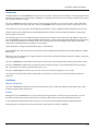
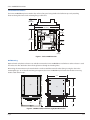
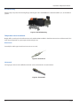
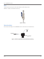
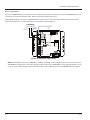
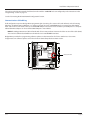
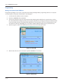
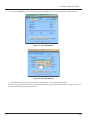
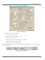
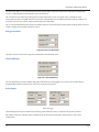
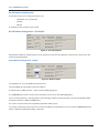
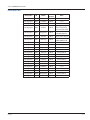
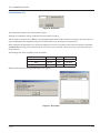
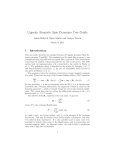
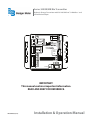
Series 340 BN/MB Btu Transmitter
Hydronic Energy Transmitter with RS-485 BACnet™ & Modbus® and
Scaled Pulse Output
Output
Sensor Input
Power Out
Signal +
Signal Shield
Pulse Out +
Output LED
Data
Industrial
Btu ENERGY METER
Model: 340 BN/MB
S/N 340- 005100
Factory Port
AC C /DC -
Power In
AC L /DC +
Pulse Out -
D.I.C.
Comm
Port
Temp 2
1 2 3
NT PU PD
Input LED
+
REF
_
Temp 1
3 2 1
Comm LED
IMPORTANT:
This manual contains important information.
READ AND KEEP FOR REFERENCE.
PN: 872035 (3-11)
Installation & Operation Manual
Series 340 BN/MB Transmitter
Page ii
3-11
Installation & Operation Manual
CONTENTS
Introduction............................................................................................................................................... 5
Installation................................................................................................................................................. 5
Mechanical installation................................................................................................................................................ 5
Location......................................................................................................................................................................... 5
Surface Mount Installation........................................................................................................................................... 6
Wall Mounting............................................................................................................................................................... 6
Din Rail Mounting......................................................................................................................................................... 7
Temperature Sensor Installation............................................................................................................................ 7
Direct Insert.................................................................................................................................................................. 7
Thermowell................................................................................................................................................................... 7
Hot Tap.......................................................................................................................................................................... 8
Electrical Installation................................................................................................................................ 8
Power Supply Wiring.................................................................................................................................................... 9
Sensor Wiring........................................................................................................................................................... 10
200 Series...................................................................................................................................................................... 10
SDI Series...................................................................................................................................................................... 10
Other Flow Sensors..................................................................................................................................................... 10
Temperature Element Wiring.................................................................................................................................. 10
Thermistors................................................................................................................................................................... 11
Resistance Temperature Detectors (RTDs)................................................................................................................ 11
Pulse Output Wiring................................................................................................................................................ 11
Connecting the RS-485 Buss................................................................................................................................... 12
Communications Cable Wiring............................................................................................................................... 13
Programming............................................................................................................................................ 14
Making Connection Via DIC COM Port................................................................................................................... 14
Flow Sensor Section................................................................................................................................. 18
Temperature Sensor Section.................................................................................................................................. 18
Energy Calculation.................................................................................................................................................. 19
3-11
Page iii
Series 340 BN/MB Transmitter
Filter Coefficients.................................................................................................................................................... 19
Pulse Output............................................................................................................................................................ 19
RS-485 Network Configurations............................................................................................................................. 20
RS-485 Network Configuration – PULSE ONLY...................................................................................................... 20
RS-485 Network Configuration – Modbus.................................................................................................................. 20
Modbus Register Map.................................................................................................................................................. 21
RS-485 Network Configuration – BACnet.............................................................................................................. 21
BACnet Object Map...................................................................................................................................................... 22
BACnet Protocol Implementation Conformance Statement..................................................................................... 23
RS-485 Network Test............................................................................................................................................... 24
Factory Default Settings......................................................................................................................................... 25
Specifications............................................................................................................................................ 26
Power........................................................................................................................................................................ 26
Flow Sensor Input.................................................................................................................................................... 26
Pulse type sensors....................................................................................................................................................... 26
Sine wave sensors:...................................................................................................................................................... 26
Temperature Sensor Input...................................................................................................................................... 26
Pulse Output............................................................................................................................................................ 26
Operating Temperature.......................................................................................................................................... 26
Weight...................................................................................................................................................................... 26
SENSOR CALIBRATION............................................................................................................................................ 26
UNITS OF MEASURE................................................................................................................................................. 26
Flow measurement....................................................................................................................................................... 26
Energy measurement................................................................................................................................................... 26
PROGRAMMING....................................................................................................................................................... 26
Page iv
3-11
Installation & Operation Manual
Introduction
The Badger Meter Series 340 BN/MB Btu transmitter is an economical, compact device for hydronic sub-metering applications.
It utilizes an RS-485 connection for Modbus® and BACnet™ communication protocols and a solid state switch for pulse output
representing either flow or energy.
The Series 340 BN/MB calculates thermal energy by integrating the liquid flow in a closed pipe system and the differential
temperature between the supply and return. The Series 340 BN/MB requires one flow sensor and two temperature sensors.
The temperature sensors can be two-wire 10 kΩ Type II Thermistors or 100 or 1000 Ohm RTDs that follow the IEC 751 curve.
The flow input may be provided by many of the Badger Meter line of flow sensors and other manufacturers' devices that
generate pulses or sine waves.
The onboard microprocessor and digital circuitry make precise measurements and produce accurate drift-free output. The
Series 340 BN/MB is programmed using the Badger Meter Windows® software and a Badger Meter Model A301 programming
cable. Calibration information for the flow sensor, units of measurement, communication protocol settings, and output
scaling may be downloaded prior to installation or in the field.
The RS-485 Modbus settings include Baud Rate, Address and RTU/ASCII.
The RS-485 BACnet is a MS/TP Slave device and includes address, Baud Rate, DeviceName, Device Instance Number and Max
Master Valve.
While the unit is connected to a PC or laptop computer real-time flow rate, flow total, both temperature readings, energy rate,
and energy total are available.
The Series 340 BN/MB transmitter features three LED’s to indicate flow sensor activity, RS-485 activity, and the pulse output.
The Series 340 BN/MB transmitter has an isolated solid state switch closure that is user programmed for units of energy or
flow. The output pulse width is adjustable from 10 mS to 5 sec.
The Series 340 BN/MB Btu transmitter operates on AC or DC power supplies ranging from 12 to 24 volts.
The compact cast epoxy body measures 3.65”(93mm) x 2.95”(75mm) and can be easily mounted on panels, DIN rails or
enclosures.
Installation
Mechanical installation
The Series 340 BN/MB transmitter may be surface mounted onto a panel, attached to DIN rails using adapter clips or wall
mounted using two optional enclosures.
Location
Although the Series 340 BN/MB device is encapsulated, all wiring connections are made to exposed terminals. The unit
should be protected from weather and moisture in accordance with electrical codes and standard trade practices.
In any mounting arrangement, the primary concerns are ease of wiring and attachment of the programming cable.
The unit generates very little heat so not consideration need be given to cooling or ventilation.
3-11
Page 5
Series 340 BN/MB Transmitter
Surface Mount Installation
The Series 340 BN/MB may be mounted to the surface of any panel using double sided adhesive tape or by attaching
fasteners through the holes in the mounting flanges of the unit.
1.60”
(40.6mm)
3.65”
(92.7mm)
Output
Sensor Input
.88”
(22mm)
Pulse Out +
Output LED
Data
Industrial
Btu ENERGY METER
Model: 340 BN/MB
S/N 340- 005100
D.I.C.
Comm
Port
Input LED
.60”
(15mm)
Temp 2
1 2 3
NT PU PD
2.95”
(74.9mm)
Pulse Out -
Factory Port
AC C /DC Power Out
Signal +
Signal Shield
Power In
AC L /DC +
+
REF
_
Temp 1
3 2 1
Comm LED
.20”
(5mm)
Figure 1: Series 340 Dimensions
Wall Mounting
Optional metal and plastic enclosures are available to mount the Series 340 BN/MB to a wall when no other enclosure is used.
The enclosure is first attached to the wall using fasteners through its mounting holes.
After wiring, the transmitter may be attached to the enclosure with the terminal headers facing in using the slots in the
mounting flanges. As an alternate mounting arrangement, the Series 340 BN/MB may be fastened to the box cover using
double-sided adhesive tape.
5.125"
Top
4.50"
Top
3.25"
4.60"
4.50"
4.60"
Side
Side
2.00"
Bottom
2.25"
Figure 2: 340 Metal (left) and Plastic (right) Box Dimensions
Page 6
3-11
Installation & Operation Manual
Din Rail Mounting
Optional clips snap onto the mounting flanges allowing the Series 340 BN/MB to be attached to DIN 15, 32, 35 mm DIN rail
systems.
Figure 3: Din Rail Mounting
Temperature Sensor Installation
Badger offers several styles of 10k Thermistors and 100 Ohm Platinum RTDs in both direct immersion and Thermowells. The
style selected depends on system requirements and pipe size.
Direct Insert
Generally for smaller pipe sizes direct insert sensors are used.
Figure 4: Direct Insert
Thermowell
For larger pipes that are more difficult to drain for service, thermowells are recommended.
Figure 5: Thermowell
3-11
Page 7
Series 340 BN/MB Transmitter
Hot Tap
For pipes that cannot be drained even for initial installation, we offer a Hot Tap version.
Model THT – available as 10k Thermistor version only.
Figure 6: Hot Tap
Electrical Installation
All connections to the Badger® Series 340 BN/MB are made to screw terminals on removable headers.
Wire
3/32" Flathead
Screwdriver
Series 300
Connector
Figure 7: Side View - Typical 300 Series Removable Connector Wiring
Page 8
3-11
Installation & Operation Manual
Power Supply Wiring
The Series 340 BN/MB requires 12-24 Volts AC or DC to operate. The power connections are made to the ORANGE header. The
connections are labeled beside the header. Observe the polarity shown on the label.
If a Badger Meter plug-in type power supply (Model A-1026 or A-503) is used, connect the black/white striped wire to the
terminal marked positive (+) and the black wire to the terminal marked negative (-).
AC or DC
Power Supply
DC or
AC Common
Earth
Ground
DC +
or
AC Load
Output
AC C /DC -
Power In
AC L /DC +
Pulse Out Pulse Out +
Output LED
Input LED
Model: 340
S/N 340- XXXXXX
Temp 2
1 2 3
Data
Industrial
REF
_
Temp 1
3 2 1
+
D.I.C.
Comm
Port
Sensor Input
Power Out
Signal +
Signal Shield
Comm LED
Figure 8: Sample Power Supply Wiring
NOTE: Included with every Series 340 BN/MB is a 340IK kit containing a screw, lock washer and nut to connect the Series
340 BN/MB to earth ground. Connect the earth ground lug of the Series 340 BN/MB to a solid earth ground with as short
a wire as possible. This will help prevent electrical interference from affecting the Series 340 BN/MB’s normal operation.
3-11
Page 9
Series 340 BN/MB Transmitter
Output
Sensor Wiring
D.I.C.
Comm
Port
Temp 2
1 2 3
NT PU PD
Input LED
Red
or Signal +
+
REF
_
Shield
(if applicable)
Temp 1
3 2 1
Series 200
or SDI Sensor
Model: 340
S/N 340- XXXXXX
Sensor Input
Power Out
Signal +
Signal Shield
Black
or Signal -
Factory Port
AC C /DC -
Pulse Out +
Power In
AC L /DC +
All flow sensor types connect to the four terminal headers labeled “Sensor Input”.
Pulse Out -
Comm LED
Figure 9: Sample Sensor Wiring Diagram
200 Series
Connect the red wire to sensor signal (+), black wire to sensor signal (-) and the bare wire to shield.
SDI Series
Connect the plus (+) terminal of the sensor to sensor signal (+) on the transmitter and the minus (-) terminal of the sensor to
sensor signal (-) on the transmitter. Connect the shield terminal of the sensor to the shield terminal of the transmitter.
Other Flow Sensors
The sensor input Power Out terminal supplies nominal 12V DC excitation voltage for 3 wire sensors. Connect sensor signal +
and sensor signal - wires to transmitter terminals.
The 340BN/MB is very versatile, and can accept both Pulse and Zero Crossing Sine Wave flow sensors. Excitation voltage is also
provided for Three Wire Powered Sensors (Example: Hall Effect, of Badger 4000 Series).
See the Programming Section for configuration instructions.
Temperature Element Wiring
Appropriate wire types and proper shielding is required for accurate temperature readings.
Since Btu calculations are based on Delta T cable, in order to maintain a balanced system, T1 and T2 wire runs should be kept
to approximately the same length, and no to exceed 500 feet.
Page 10
3-11
Installation & Operation Manual
Thermistors
Badger Meter thermistors are not polarity-sensitive, therefore, wire color is unimportant. The thermistor located in the same
pipe as the flow sensor, termed temperature sensor T1, should be connected to terminals 2 and 3 on terminal block Temp 1.
The thermistor located other pipe, termed temperature sensor T2, should be connected to terminals 2 and 3 on terminal block
Temp 2. As shown in the thermistor wiring diagram, a jumper must be installed between terminals 1 and 3 for both the T1
and T2 input terminals. These terminals 1 and 3 are used for lead resistance compensation when 100 three wire RTDs are used,
and must be jumpered when not used.
Supply
Temp 1
3 2 1
Return
Temp 2
1 2 3
Jumpers
T1
T2
10KΩ Thermistors
Figure 10: Thermistor Wiring Diagram
Resistance Temperature Detectors (RTDs)
Badger Meter RTDs are three-wire devices. Two of the wires are the same color, and interchangeable. One wire is currentcarrying and connects to terminal #3, and the other is used for lead compensation and is connected to terminal #1. The
single color lead is attached to terminal 2. The RTD located in the same pipe as the flow sensor, termed temperature sensor T1,
should be connected to terminal block Temp 1. The RTD located in the other pipe line, termed temperature sensor T2, should
be connected to terminal block Temp 2.
Temp 2
1 2 3
Supply
Return
Temp 1
3 2 1
T2
T1
100Ω RTDs or 1000Ω RTDs
Figure 11: RTD Wiring Diagram
Pulse Output Wiring
The Badger Meter Series 340 BN/MB has solid state switch output rated for a maximum sinking current of 100 mA @ 36V
DC. In most cases the pulse out (+) terminal of the Series 340 BN/MB will connect to the input pulse (+) and the pulse out (-)
terminal to the input pulse (-) of the receiving device. Although labeled +/-, the pulse output is not actually polarity sensitive,
and can switch low level AC loads if required.
These terminals are located on a separate two terminal removable header on the Series 340 BN/MB labeled “Output”.
3-11
Page 11
Series 340 BN/MB Transmitter
NOTE:
maximum sinking current
is 100 mA @ 36 VDC
Output
AC C /DC -
Power In
AC L /DC +
Pulse Input
Device
(-) (+)
Pulse Out Pulse Out +
Output LED
Figure 12: Sample Pulse Output Wiring Diagram
Connecting the RS-485 Buss
As shown in the Sample Wiring Diagram, the position of jumpers on each 340MB/BN transmitter and wiring between each
340MB transmitter and the RS-485 network are different depending on where the transmitter is installed, i.e. its nodal
position. For all but the final 340MB transmitter in a string, the three jumpers NT, PU, and PD should be in the open position,
and only the (+) and (-) network terminals should be connected to the RS-485 buss. For the final 340MB transmitter in a
Modbus network, the three jumpers NT, PU, and PD should be in the closed position, and all three network terminals (+), (-),
and REF should be connected to the Modbus buss.
NOTE: The Model 340MB/BN transmitter default Modbus or BACnet polling address must be changed before it is
introduced into an existing network to avoid possible address conflicts. Please refer to programming instructions in the
previous section.
Figure 13: Sample Wiring Diagram to Modbus Network
Note 1: Biasing, circuitry, and resistors for PU, PD, and NT terminals are integral part of 340BN/MB transmitter.
Note 2: For the final 340MB transmitter in a given RS-485 network string, NT, PU, and PD jumpers should be in “Closed”
position. Otherwise, NT, PU, and PD should be in the “Open” position.
Note 3: For the final 340MB transmitter in an RS-485 string, all three network terminals (+), (-), and REF should be connected
to the buss. Otherwise, connect only terminals (+), (-) to the buss.
Page 12
3-11
Installation & Operation Manual
Connection to the RS-485 network should not be made until the 340BN/MB has been configured per the instructions in the
"Programming" section on page 14.
See the “Connecting the RS-485 Network Configuration” Section.
Communications Cable Wiring
Field configuration requires a Badger Meter programming kit (consisting of a custom cable and software) and a PC running
Windows® 9x, ME, NT, 2000, or Windows 7. In order to connect, the Series 340 BN/MB must be to powered, and the Model
A301 cable must be connected to the Series 340 BN/MB COM port connector and an available 9-pin COM port on a computer.
USB to COM Port adapters can be used if the DB9 COM port is not available.
NOTE: The Badger Meter A301 Cable will work with all Series 300 products. However the older version of the cable (A300)
does not have sufficient bandwidth to work with the Series 340 BN/MB Transmitters.
Badger Meter provides free programming software updates via the Internet for all of Series 300 devices. Go to www.
badgermeter.com. Software update can be found in the Industrial/Impeller/transmitter section.
Output
Sensor Input
Power Out
Signal +
Signal Shield
Pulse Out +
Output LED
Data
Industrial
Btu ENERGY METER
Model: 340 BN/MB
S/N 340- 005100
Factory Port
AC C /DC -
Power In
AC L /DC +
Pulse Out -
D.I.C.
Comm
Port
D.I.C. Comm Port
Temp 2
1 2 3
NT PU PD
Input LED
+
REF
_
Temp 1
3 2 1
Comm LED
Figure 14: Location of the DIC COM Port
3-11
Page 13
Series 340 BN/MB Transmitter
Programming
Making Connection Via DIC COM Port
Programming the Badger® Series 340 is accomplished by installing the Badger Meter programming software on a computer
and entering data on templates of the Windows® based program.
1. Load the interface software into the computer.
2. Power the 340BN/MB with 12-24V AC/DC
3. Connect the computer to the Series 340 transmitter with the Badger Meter Model A-301 communications cable to
the socket labeled “D.I.C. COM port”, taking care to properly align the tab on the plug and socket to maintain polarity.
Connect the DB9 connector of the Badger Meter Model A301 communications cable to a PC COM port that has the
340 software installed. If a DB9 COM port is not available a USB to COM Port Adapter may be purchased locally.
4. Open the program, and from the DEVICE tab select 340 as shown in the dialog box below.
Figure 15: Select 340
5. After the 340 device has been selected, the specific 340BN/MB can be selected
Figure 16: Device Type
Page 14
3-11
Installation & Operation Manual
6. Once the 340BN/MB has been selected the appropriate COM port can be selected from the Configuration Tab.
Figure 17: Select Set COM Port
Figure 18: Select the COM Port
7. If the COM and Device type have been properly selected, the “---” will be replaced with values.
If this does not occur, communication has not been established, and you cannot continue to the next step. If it does not
connect automatically try clicking on “Poll Now”.
3-11
Page 15
Series 340 BN/MB Transmitter
If communication still does not occur, and you are using a DB9 to COM 1 or COM2, try using a USB to COM adapter. This
will usually create a new COM port that was not previously listed. Windows Device Manager can be helpful in determining
the actual COM ports that are available.
Figure 19: Device Manager
Select this new port created by the adapter, and the screen should change to as shown on the next page which will confirm
normal communications.
Notice that the “---“ are replaced with values. This confirms communications.
Figure 20: Screen Change
Page 16
3-11
Installation & Operation Manual
8. When communication has been confirmed, Click on the Parameters button.
Figure 21: Parameters Screen
9. From this screen we will set up the following:
1. Flow Sensor Type, Scaling, and units.
2. Temperature Sensor Type, Units, Mode, and Zeroing.
3. Energy Calculation Units of Measure
4. Filter Coefficients ( Flow and Energy averaging for reading stability)
5. Scaled Pulse Output resolution and pulse width
6. RS-485 Network Configuration ( BACnet or Modbus)
Be sure to press Send before leaving this page to save any wanted changes. Defaults will restore all factory settings. Exit
returns to the Main Screen.
Figure 22: Parameter Screen Buttons
3-11
Page 17
Series 340 BN/MB Transmitter
Flow Sensor Section
Figure 23: Pulse or Sine
For most Badger Meter sensors the sensor type is “Pulse”, and the “K” and “Offset” values can be found in the respective Flow
Sensor Manual.
“Sine” is used for zero-crossing flow sensors (some turbine meters, etc.)
Several flow rate and flow total units of measure can be selected from the pull-down menu.
Temperature Sensor Section
Figure 24: Sensor Attributes
First choose the sensor type ( 10K Thermistor, 100 Ohm RTD, or 1K RTD).
The calculation mode has three selections.
Initially, it is best to choose “Absolute.” In this mode the Energy Rate and Total will be calculated as a positive value regardless
of the direction of energy flow.
In the T1>T2 Mode, energy will only be calculated if the T1 sensor is warmer than the T2 sensor.
If T1 is cooler than T2, the energy rate will remain at 0.0, and the energy total will not increase.
In the T1<T2 Mode, energy will only be calculated if the T1 sensor is cooler than the T2 sensor.
The T1= and T2= are simply for reference to indicate the current temperature readings.
This is useful in using the zeroing Feature explained on page 19.
Page 18
3-11
Installation & Operation Manual
The “Zero Temp Diff” is a very powerful feature in this product which allows any inaccuracies of drift in the temperature
sensors, or 340 temperature measurements to be cancelled out.
This correction can be either manually typed in or if the temperature sensors are known to be at exactly the same
temperature, the “Zero Temp Diff” button can be used to automatically zero the difference between the two readings. To
correct for any erroneous entries, simply manually type 0.0 in both fields.
This is a very powerful feature, but must be used with caution. If used incorrectly, the temperature readings will be incorrect
and the energy rates and totals will also be in error.
Energy Calculation
Figure 25: Rate and Total Units
Select the units of measure for energy rate and total from the Pull-Down menu.
Filter Coefficients
Figure 26: Filter Coefficients
For most applications leave the default setting of 5. If the Flow rate or Energy Rates are some reason unstable (from a
disturbed flow profile for example). This value can be increased as needed.
Pulse Output
Flow or Energy
The Pulse Output can represent either Flow or Energy. Units will be the same as selected in the previous sections.
Pulse width, and pulse resolution will be selected based on the requirements of the receiving device, and system
requirements.
3-11
Page 19
Series 340 BN/MB Transmitter
RS-485 Network Configurations
The RS-485 Section can be configured in three ways:
-- PULSE OUT only – RS-485- OFF
-- Modbus
-- BACnet
The following sections explain each in detail.
RS-485 Network Configuration – PULSE ONLY
Figure 27: Pulse Only Option
If the Modbus or BACnet communications are not going to be used, the “Pulse Out Only” setting can be selected. This will
disable the RS-485 Network.
RS-485 Network Configuration – Modbus
Figure 28: Modbus Option
Select Modbus, to access the Modbus pull down menus.
Select the BAUD rate, Mode (RTU or ASCII) and address.
The Model 340 uses IEEE 754 Float - Data Located in “Holding Registers”
The 340BN/MB Data Format is “Float 32” where the Data is Stored across two “Holding Registers”.
In the case of Temperature 1, the Upper Byte is stored in Register 40002, and the lower Byte is stored in the Register 40001.
Sometimes referred to a ABCD to CDAB format.
This is done to permit backwards compatibility with older 16 Bit Systems.
For example a temperature of 53.36°F when converted to IEEE 754 is “425570A4.” So in the case of the 340BN/MB, Register #
40001 = 70A4 Hex and Register # 40002 = 4255 Hex.
Page 20
3-11
Installation & Operation Manual
Modbus Register Map
MODEL 340BN/MB Register Map
Register Name
Address
Data Type
Read/Write
Temperature 1
40001 + 40002
IEEE 754 Float
Read Only
Temperature 2
40003 + 40004
IEEE 754 Float
Read Only
Flow Input (Hz)
40005 + 40006
IEEE 754 Float
Read Only
Total Flow
40007 + 40008
IEEE 754 Float
R/W
Total Energy
40009 + 40010
IEEE 754 Float
R/W
Flow Rate
40011 + 40012
IEEE 754 Float
Read Only
Energy Rate
40013 + 40014
IEEE 754 Float
Read Only
K Factor
40015 + 40016
IEEE 754 Float
R/W
Offset
40017 + 40018
IEEE 754 Float
R/W
Temp. Calc. Mode 40019 + 40020
IEEE 754 Float
R/W
Flow Filter Coef.
40021 + 40022
IEEE 754 Float
R/W
Temp. Filter Coef.
40023 + 40024
IEEE 754 Float
R/W
Specific Heat
40025 + 40026
IEEE 754 Float
R/W
Fluid Density
40027 + 40028
IEEE 754 Float
R/W
T1 A Coefficient
40029 + 40030
IEEE 754 Float
R/W
T1 B Coefficient
40031 + 40032
IEEE 754 Float
R/W
T1 C Coefficient
40033 + 40034
IEEE 754 Float
R/W
Temp 1 Offset
40035 + 40036
IEEE 754 Float
R/W
T1 A Coefficient
40037 + 40038
IEEE 754 Float
R/W
T1 B Coefficient
40039+ 40040
IEEE 754 Float
R/W
T1 C Coefficient
40041 + 40042
IEEE 754 Float
R/W
Temp 1 Offset
40043 + 40044
IEEE 754 Float
R/W
RS-485 Network Configuration – BACnet
Figure 29: BACnet Option
Select BACnet, to access the BACnet pull down menus.
Select the BAUD rate to match other devices on the network.
BACnet Device Name can be set to help identify this device and location.
BACnet Device ID ( Incidence #) is a unique number to identifies this device on the network.
Typically, the first part of the number is the same network #, and the last two characters are the same as the Address.
This is not a requirement, but can help in system planning.
3-11
Page 21
Series 340 BN/MB Transmitter
BACnet Object Map
Page 22
Description
ID
Name
Out of
Service
Units
Analog Input
AN1
TempIn
FALSE
ºC, ºF
Analog Input
AN2
TempOut
FALSE
ºC, ºF
Analog Input
AN3
FreqIn
FALSE
Hz
Analog Input
AN4
VolFlow
FALSE
gpm, gph, lpm, lph,
ft3/s, ft3/m, ft3/h,
m3/s, m3/min, m3/h
Analog Input
AN5
EnrgyFlow
FALSE
kBTU/min, kBTU/h,
kW, MW, HP, Tons
Analog Value
AV1
TotalVol
FALSE
gallons, liters, ft3, m3
Analog Value
AV2
TotEnergy
FALSE
BTU, kBTU, MBTU,
kWh, MWh, kJ, MJ
Analog Value
AV3
Kfactor
FALSE
dimensionless
Analog Value
AV4
Offset
FALSE
dimensionless
Analog Value
AV5
TempMode
FALSE
dimensionless
Analog Value
AV6
FFilterCoef
FALSE
dimensionless
Analog Value
AV7
TFiltCoef
FALSE
dimensionless
Analog Value
AV8
SpHtCapac
FALSE
BTU/lb-F
Analog Value
AV9
Density
FALSE
lb/gallon
Analog Value
AV10
InTACoef
FALSE
dimensionless
Analog Value
AV11
InTBCoef
FALSE
dimensionless
Analog Value
AV12
InTCCoef
FALSE
dimensionless
Analog Value
AV13
InTOffset
FALSE
ºC, ºF
Analog Value
AV14
OutTACoef
FALSE
dimensionless
Analog Value
AV15
OuTBCoef
FALSE
dimensionless
Analog Value
AV16
OutTCCoef
FALSE
dimensionless
Analog Value
AV17
OutTOffset
FALSE
ºC, ºF
3-11
Installation & Operation Manual
BACnet Protocol Implementation Conformance Statement
3-11
Page 23
Series 340 BN/MB Transmitter
RS-485 Network Test
Figure 30: RS-485 Test
The Configuration Software has an RS-485 test program.
Although it uses Modbus settings, it is RS-485 communication it is testing.
The test requires connection to a COM port using the Badger Meter A302-20 RS 485 to RS-232 convertor cable. This cable can
also be helpful with other diagnostics programs and devices that use an RS-232 port to communicate.
When testing the RS-485 network, it is sometimes helpful to connect to some other location instead of directly to the Model
340BN/MB. When testing in this way the RS-485 end connector can be removed, and the wires can be connected directly to
the RS-485 pairs.
The following table may be helpful to make connections.
302 Cable -RS-485 End
340BN/MB
340N2
Series 3000
Red
RS-485 +
N2+
RS-485B
White
RS-485 -
N2-
RS-485A
Black
REF
REF
RS-485 Gnd
When the “RS-485 Test” is clicked the following screen appears:
Figure 31: Test Screens
Page 24
3-11
Installation & Operation Manual
Factory Default Settings
The table below is a list of factory default setting for all 340BN/MB variables. These settings can be changed by accessing the
parameters to best fit your application, and if desired, recorded in the table for future reference.
Description
Default Value
Flow Sensor Type
Pulse
"K" Offset
1
"Offset" Value
0
Flow Rate
gpm
Flow Total
gallons
Temperature
ºF
Energy Calculation
absolute
Temperature Sensor Type
thermistor
Energy Rate
kBTU/hr
Energy Total
BTU
Flow Filter Coefficient
5
Energy Filter Coefficient
1
Energy Folter Coefficient
1
MS/TP Address
1
MS/TP Baud Rate
9600
Customer Value
BACnet Device #
BACnet Max Master
3-11
127
Page 25
Series 340 BN/MB Transmitter
Specifications
Power
Power supply options:
12-35V DC +/- 5%
12-24V AC +/- 10%
Current draw:
60 mA @ 12V DC
Flow Sensor Input
Pulse type sensors
Signal amplitude:
2.5V DC threshold
Signal limits:
Vin < 12V (DC or AC peak)
Frequency:
0.25-10kHz
Pull-up:
2 kΩ to 10V DC
Sine wave sensors:
Signal amplitude:
10 mV p-p threshold
Signal limits:
Vin < 12V (DC or AC peak)
Frequency:
0 to10kHz
Excitation voltage 3-wire sensors
7.0V DC to 11.4 V DC 500Ω source impedance
Temperature Sensor Input
2 required:
10 kΩ thermistor, 2 wire, type II,10 kΩ, @ 25°C
100Ω RTD, Platinum three wire,
1000Ω RTD, Platinum, Two or Three wire
RTDs follow IEC 751 DIN Curve @0°C
Pulse Output
Operating Temperature
-29° C to +70° C
-20° F to +158° F
Storage Temperature
-40° C to +85° C
-40° F to +185° F
Weight
4.8 oz. with connector headers installed
SENSOR CALIBRATION
Badger Meter
Use K and Offset provided in sensor owner’s manual
Other Sensors
Check with factory
UNITS OF MEASURE
Flow measurement
Rate:
gpm, gph, l/sec, l/min, l/hr, ft3/sec, ft3/min,
ft3/hr, m3/sec, m3/min, m3/hr
Total:
gallons, liters, cubic feet, cubic meters
Energy measurement
Rate:
kBtu/min, kBtu/hr, kW, MW, hp, tons
Total:
Btu, kBtu, MBtu, kWh, MWh, kJ, MJ
Temperature Units:
Fahrenheit, Centigrade
PROGRAMMING
Requires PC or laptop running Windows® XP, Vista or
Windows 7
Badger Meter Model A-340 programming kit containing
software and Model A301-20 programming cable
Pulse width:
Programmable 10mS to 5 sec. in 50mS steps
Pulse frequency:
Max of 10Hz @ 50mS pulse width Programmable to scaling
requirements of connected device ( Flow or Energy)
Opto-isolated solid state switch
Operating Voltage range:
0 to ±45V (DC or AC peak)
Closed (on) state:
Load Current - 700mA max.
over operating temperature range
Open (off ) state - leakage @ 70ºC
<1µA @ 45V (DC or AC peak)
Page 26
3-11
Installation & Operation Manual
Blank Page
3-11
Page 27
Data Industrial is a registered trademarks of Badger Meter, Inc.
Other trademarks appearing in this document are the property of their respective entities.
Copyright 2011, Badger Meter, Inc. All rights reserved.
Please see our website at www.badgermeter.com
for specific contacts.
Due to continuous research, product improvements and enhancements,
Badger Meter reserves the right to change product or system specifications
without notice, except to the extent an outstanding contractual obligation exists.
Badger Meter | P.O. Box 245036, Milwaukee, Wisconsin 53224-9536
800-876-3837 | [email protected] | www.badgermeter.com