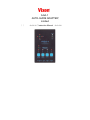
1
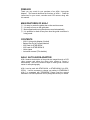
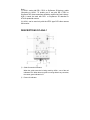
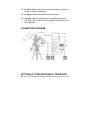
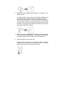
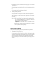
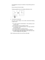
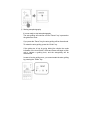
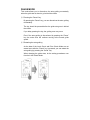
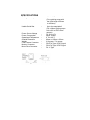
AGA-1
AUTO-GUIDE ADAPTER!
Limited
! !
✍✍✍✍! Instruction Manual
✍✍✍✍
PREFACE
Thank you very much for your purchase of an AGA-1 Auto-guide
Adapter. This manual describes the functions of AGA-1. Read the
instructions for your mount, controller and CCD camera along with
this manual.
MAIN FEATURES OF AGA-1
Ⓓ
Ⓔ
Ⓕ
Ⓖ
It is easy to center the guide star on the monitor screen.
It is easy to focus on the guide star.
Motor speed and turning direction are read automatically.
It is possible to check at any time how the guide correction is
being made.
CONTENTS
-
AGA-1 Auto-guide Adapter (Limited)
Battery Box for 8x D-sized batteries
AGS cord for STAR BOOK
AGS cord for STAR BOOK-S
Velcro tapes
Instruction manual (This booklet)
AGA-1 AUTO-GUIDE ADAPTER
AGA-1 detects the deviation of the guide star imaged through a CCD
video camera, and allows the motor drive system to correct it
automatically. Thus this instrument helps to make guide correction
easier for astrophotography.
AGA-1 can be used with STAR BOOK, or STAR BOOK-S (for GP2,
GPD2). It will be necessary to change your setting in STARBOOK If
AGA-1 is connected with STARBOOK. Please read the manual
attached to SX/SXD equatorial mount (Autoguider section) for details.
Note:
(1) AGA-1 works with DD-1, DD-2 or SkySensor 3D having a cable
connecting to AGA-1. To enable you to use with DD-1, DD-2 or
SkySensor 3D, these controllers should be modified at Vixen’s factory.
AGA-1 cannot be used with DD-1 or SkySensor 3D attached to
ATLUX equatorial mounts.
(2) AGA-1 can be used only with the NTSC type CCD video camera
and monitor.
DESCRIPTIONS OF AGA-1
Ⓓ Guide Correction Indicators
When the guide correction is being made by AGA-1, one of the red
indicators is lit. When the auto-guide is running without any correction,
the center green indicator is lit.
Ⓔ Power-On Indicator
When switching on, the power-on indicator is a green light. If the
power voltage becomes insufficient, it will change to a red light.
Ⓕ Power Switch
When switching on again, wait more than three seconds after
switching off.
Ⓖ Mode Indicators
Ⓗ “LEVEL CHECK” Key
If you press this key after centering the guide star on the monitor
screen, it will check if the guide star is bright enough to use. This key
is also used for resetting AGA-1.
Ⓘ “DRIVE CHECK” Key
If you press this key after checking the brightness of the guide star, it
will check the motor speed and turning direction, and will begin the
auto-guiding.
Ⓙ “GUIDE” Key
If you press this key after checking the motor speed and turning
direction, it will begin the auto-guiding.
Ⓚ “PAUSE” Key
If you press this key, the auto-guiding will be discontinued.
Ⓛ Motor Drive Connector
This is for output of the auto-guiding signals.
Ⓜ Power Cord Connector
A DC12V can be used with this instrument. When connecting a power
cord, make sure that the polarity of the power cord is correct.
Ⓝ CCD Camera Connector
This is to input signals of a CCD video camera.
Ⓞ Monitor Connector
This is for output of signals to a monitor.
HOW TO USE AGA-1
AGA-1 detects deviation of the guide star imaged through the CCD
video camera installed on a guide scope, and it automatically
corrects tracking errors in astrophotography. Center the guide
star on the screen of your monitor and bring it into focus before you
operate the AGA-1.
There are four modes of operation in the AGA-1.
(1) The Level Check mode will let you know if a star you selected
is bright enough to use as a guide star. It also works as a
re-set key for the whole system.
(2) The Drive Check mode will set up the speed and direction of
the drive motors automatically.
(3) The Guide mode will proceed to the auto-guiding.
(4) The Pause mode will suspend the auto-guiding temporarily.
The AGA-1 will go back to the auto-guiding again if the Guide
key is pressed.
CONNECTION DIAGRAM
SETTING UP YOUR EQUATORIAL TELESCOPE
Set up your equatorial telescope and align the polar axis of the
telescope precisely as you do for guided astrophotography. Attach a
guiding scope, a CCD video camera and a camera to the telescope.
[TIPS ON SETTING UP]
(a) Align the polar axis precisely.
The polar axis must be aligned precisely to enable the autoguiding
to be within the range of the guiding error allowance.
(b) To attach the CCD video camera to the guiding scope, an optional
T-C ring as well as an optional camera adapter 36.4mm type or
43mm type is needed.
(c) The appropriate combined focal length of the guiding scope
depends on the photographic lens you use, but it should be
1000mm to 2500mm.
If it is shorter, the guiding accuracy will not be sufficient. If it is
longer, the motor speed and turning direction check (Drive Check
Mode) will not function well.
Even if you use a guiding scope with the excessively long focal
length, the guiding accuracy will not become higher.
(d) The use of a high-sensitivity monochrome CCD video camera with
a C-mount lens adapter is recommended for AGA-1.
A color CCD video camera is not sensitive enough.
CONNECTING AGA-1
After Setting up the telescope, connect AGA-1 to the motor drive
controller, CCD video camera and monitor. At this time, make sure
that each instrument is switched off.
1. Connecting AGA-1 to the CCD video camera
Attach the video output cable to the CCD camera connector of
AGA-1.
2. Connecting AGA-1 to the monitor
Attach the monitor cable to the monitor connector of AGA-1.
3. Connecting AGA-1 to the monitor drive controller
Attach the motor drive cable of the controller to the motor drive
connector of AGA-1.
Connecting with STAR BOOK or SkySensor 2000PC:
Use the supplied AGS cord
Connecting with STAR BOOK-S:
Use the supplied AGS cord for STAR BOOK-S.
4. Switching on each instrument
After making sure that each instrument is connected correctly, turn
on their power switches. If AGA-1 receives signals correctly from
the CCD video camera, crosshairs will appear on the monitor
screen.
LEVEL CHECK MODE
This mode is to check if brightness of the guide star you selected is
good for AGA-1. (In case of using a 60mm guiding scope, the
appropriate magnitude of the guide star is 1 to 3.)
1.
Centering the guide star on the monitor screen
Center the guide star on the monitor screen and bring into focus.
2.
Setting the right ascension and declination accurately on the
monitor screen.
To correctly set the right ascension and declination displayed on
the monitor screen, center the guide star and bring into focus.
After centering the guide star on the cross, press the stop key of
the motor drive. At that time, look at the direction of the guide star
movement. The direction of the guide star movement is the right
ascension. Put the guide star upon the horizontal line of the cross
by turning the CCD video camera.
3.
Select a motor drive speed which is appropriate to the focal length
of your telescope for photography. The longer the focal length,
the slower the speed you set to allow for finer adjustments.
4.
Checking brightness of the guide star
If you press the “Level Check” key, AGA-1 will begin to check if
brightness of the guide star you selected is good. The middle
green indicator goes on and off during checking.
If its brightness is good, the indicator will stop going on and off and
will remain it.
If the guide star is too bright for AGA-1, the [+] red indicator will be
lit.
If it is too dark, the [-] red indicator will be lit.
5.
Finding another guide star
If the guide star is too bright or too dark, find another guide star.
After centering it on the monitor screen, press the “Level Check”
key again.
Note: a) The “Level Check” key is also used for resetting AGA-1.
For rechecking brightness of the guide star, press the
key and all the LED lights will go out.
If you press the key again, AGA-1 will begin to check
brightness.
b) Avoid using a double star as the guide star. The double
star may cause trouble in guiding.
DRIVE CHECK MODE
This mode allows checking the motor speed and turning direction.
1.
Pressing the “Drive Check” key
If you press the “Drive Check” key, AGA-1 will have the right
ascension and declination motors begin to drive and will compute
the moving direction and speed of the guide star automatically.
During computing, the drive check indicator’s green light goes on
and off.
If it is finished correctly, the indicator will stop blinking and will
remain lit.
Now you can go to the next mode.
If there is something wrong, the indicator will light up in red.
! ! !
2.
Correcting the instruments
If the drive check indicator is red, make sure that the following
conditions exist:
♎! The right ascension and declination is set accurately on the
monitor screen.
♎! The motor drive speed is selected correctly.
♎! The telescope is balanced properly on the right ascension
and declination axes.
♎! The motor cables are connected securely.
♎! The right ascension and declination clamps are fastened.
♎! The gear wheels of the slow-motion control shaft and motor
are set to engage each other properly.
After checking, begin with the Level Check mode again.
GUIDE MODE
This mode allows you to begin the autoguiding.
Ⓓ! Pressing the “Guide” key
If you press the “Guide” key, AGA-1 will automatically control the
motor drive to center the guide star on the monitor screen.
During centering the guide star, the green guide indicator will
blink.
When the guide star is centered, the indicator will become solid
green.
Note:
After pressing the key, it takes a few seconds to a few
minutes to begin the auto-guiding. It depends on
where the guide star is on the monitor screen.
!
Ⓔ Starting astrophotography
It is now ready to start astrophotography.
The auto-guiding will continue until the “Pause” key is pressed or
the guide star is lost.
If you press the “Pause” key, the auto-guiding will be discontinued.
To restart the auto-guiding, press the “Guide” key.
If the guide star is lost by going behind the clouds, the mode
indicators of the Level Check, Guide and Pause will begin to blink
red to indicate a guiding error, and the autoguiding will be
discontinued.
In case of such a guiding error, you cannot restart the auto-guiding
by pressing the “Guide” key.
PAUSE MODE
This mode allows you to discontinue the auto-guiding momentarily
when the guide star is about to go behind the clouds.
Ⓓ! Pressing the “Pause” key
By pressing the “Pause” key, you can discontinue the auto-guiding
momentarily.
The key should be pressed before the guide star goes in behind
the clouds.
If you delay pressing the key, the guiding error may occur.
Even if the auto-guiding is discontinued by pressing the “Pause”
key, the motor drive will continue running at the normal guide
speed.
Ⓔ! Restarting the auto-guiding
As the data of the Level Check and Drive Check Mode are not
erased even after the “Pause” key is pressed, you can restart the
auto-guiding by pressing the “Guide” key.
When changing the guide stars, do the setting procedures over
from the Level Check Mode.
SPECIFICATIONS
Guiding Accuracy
:
About ² 15 arc seconds
(For a guiding scope with
the focal length 1000mm
to 4000mm)
Usable Guide Star
:
Power Source Voltage
Power Consumption
Operational Temperature
Outside Dimension
Weight
CCD Camera Connector
Monitor Connector
Motor Drive Connector
:
:
:
:
:
:
:
:
Up to the magnitude 3
(For a 60mm guiding scope
with a 0.2 lux CCD video
camera)
DC 9V to 15V
About 150mA
0΅C to 40΅C
80mm x 125mm x 32mm
210 grams / 7.4 ounces
RCA Pin Type, NTSC Signal
RCA Pin Type, NTSC Signal
RJ-11 Type