1
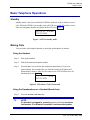
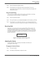
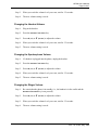
UIP200 User's Manual
Revision 1.0
© Uniden America Corp., May, 2004
This manual contains instructions for installing and operating your UIP200 SIP IP phone. It
provides a description of the telephone’s hardware, features, LCD displays, and explains setup,
configuration, and basic operation. If you have any questions about the information in this
document, please call our Customer Service Department at 1-800-648-4921 or visit us on the
web at http://bcs.uniden.com.
UIP200 User's Manual
Page 2 of 27
Table of Contents
Introduction ......................................................................................................... 5
Document Conventions....................................................................................................... 5
Warnings, Cautions, Notes, and Timesavers...................................................................5
Regulatory Information....................................................................................................... 6
FCC Part 15 .....................................................................................................................6
U.L. Compliance .............................................................................................................6
Industry Canada (ICES-003) ...........................................................................................6
Hearing-Aid Compatibility .............................................................................................6
Recording Conversations ................................................................................................6
What’s New?....................................................................................................................... 6
Important Safety Considerations......................................................................................... 7
Important Electrical Considerations ................................................................................... 8
The FCC Wants You to Know............................................................................................ 8
AC Adapter ......................................................................................................................... 9
Power over Ethernet (PoE)..............................................................................................9
Product Description .......................................................................................... 10
Features ............................................................................................................................. 10
VoIP Specific Features..................................................................................................10
Operational Features......................................................................................................11
Control and Functions....................................................................................................... 11
Function Keys ................................................................................................................... 12
LED Status ....................................................................................................................12
Specifications.................................................................................................................... 12
Physical Interface ..........................................................................................................13
Power Supply ................................................................................................................13
Speaker ..........................................................................................................................13
Installation and Basic Setup Instructions....................................................... 14
Wall-Mounting the Telephone.......................................................................................... 14
Connecting the Telephone ................................................................................................ 15
Basic Telephone Operations............................................................................ 16
Standby ............................................................................................................................. 16
Rev. 1.0, © UAC, May, 2004
UIP200 User's Manual
Page 3 of 27
Making Calls..................................................................................................................... 16
Using the Handset .........................................................................................................16
Using the Speakerphone or a Headset (Hands-free) .....................................................16
Using On-Hook Dialing ................................................................................................17
Receiving Calls ................................................................................................................. 17
Adjusting the Volume ....................................................................................................... 17
Changing the Handset Volume......................................................................................17
Changing the Headset Volume......................................................................................18
Changing the Speakerphone Volume ............................................................................18
Changing the Ringer Volume........................................................................................18
Transferring a Call ............................................................................................................ 19
Call Waiting Operation ..................................................................................................... 19
Hold 19
Feature Operations ........................................................................................... 20
Programmable and Fixed Function Keys.......................................................................... 20
1-Touch Dialing ............................................................................................................20
2 -Touch Dialing ...........................................................................................................21
DND ..............................................................................................................................21
Voice Message Access ..................................................................................................21
Mute...............................................................................................................................22
Dial (fixed key) .............................................................................................................22
Emergency Proxy.............................................................................................................. 22
Configuring the Telephone............................................................................... 23
Navigating the Menus ....................................................................................................... 23
Speed Dial Sub-Menu ....................................................................................................... 23
Programming a 1-Touch Number..................................................................................23
Clearing or Editing the 1-Touch Number......................................................................24
Programming the 2 Touch Number...............................................................................24
Clearing or Editing the 2-Touch Number......................................................................25
Phone Settings Sub-Menu................................................................................................. 25
Changing the LCD Contrast ..........................................................................................25
Changing the Display Language ...................................................................................25
Adjusting the Date and Time.........................................................................................26
Network Setting ................................................................................................................ 27
View Info .......................................................................................................................... 27
Rev. 1.0, © UAC, May, 2004
UIP200 User's Manual
Page 4 of 27
Figures in This Document
Figure 1
Figure 2
Figure 3
Figure 4
Figure 5
Attaching the Wall Mount Bracket...........................................................................14
Mount the Phone on the Wall Plate..........................................................................14
LCD in standby mode...............................................................................................16
LCD when a Call is Connected ................................................................................16
LCD display when Receiving a Call ........................................................................17
Tables in This Document
Table 1
Table 2
Table 3
Table 4
Table 5
Revision History .........................................................................................................6
Control Keys and Their Functions............................................................................11
LEDs and Their Meanings ........................................................................................12
Fixed-Function Key and Programmable Key Defaults.............................................20
Configuration Menus and Their Functions ...............................................................23
Rev. 1.0, © UAC, May, 2004
UIP200 User's Manual
Page 5 of 27
Introduction
Document Conventions
Warnings, Cautions, Notes, and Timesavers
This document uses particular conventions for warnings, cautions, notes and
timesavers. Below is an example of these conventions and how they are used:
WARNING
Warnings appear with the stop sign. They indicate there is
extreme danger or a risk of injury if the instructions are not
followed correctly. Some warnings are required by
government regulation or company policy.
CAUTION
Cautions appear with the “slow” sign. They indicate there is a
danger of damaging the equipment or causing a missioncritical problem if the instructions are not followed correctly.
Some cautions are required by government regulation or
company policy.
!
!
NOTE
Notes point out important and useful information that the user
should remember, but there is no danger. Most notes are
based on by suggestions from users or frequent questions to
support personnel.
TIMESAVER
Timesavers are hints that will make things go a little faster.
Most timesavers are suggestions from users that have
worked well in the field.
Rev. 1.0, © UAC, May, 2004
UIP200 User's Manual
Page 6 of 27
Regulatory Information
FCC Part 15
This product complies with the limits for a Class B computing device pursuant to
Sub part B of Part 15 of FCC Rules.
U.L. Compliance
This equipment complies with Underwriters Laboratories Standard U.L. 60950.
Industry Canada (ICES-003)
This class B digital apparatus complies with Canadian ICES-003. Users should not
attempt to make such connections themselves, but should contact the appropriate
electric inspection authority, or electrician, as appropriate.
Hearing-Aid Compatibility
The equipment is hearing-aid compatible.
Recording Conversations
The act of monitoring or recording telephone conversations under certain
circumstances may violate federal or state statutes. Consult your legal counsel prior
to monitoring or recording any telephone conversation.
CAUTION
No repairs can be done by the customer! Attempting repairs
will damage the equipment and void your warranty!
What’s New?
This is the first release of documentation for this product.
Table 1
Revision History
Revision
Publication Date
1.0
May 31, 2004
Changes
First release of this document.
Rev. 1.0, © UAC, May, 2004
UIP200 User's Manual
Page 7 of 27
Important Safety Considerations
When using this product, basic safety precautions should always be followed to
reduce the risk of fire, electrical shock and injury to persons, including but not
limited to the following:
#
Read and understand all instructions.
#
Follow all warnings and instructions marked on the product.
#
Unplug this product from the wall outlet and network connection before
cleaning. Do not use liquid cleaners or aerosol cleaners. Use a dry cloth for
cleaning.
#
Do not use this product near water; for example, near a sink or in a wet area.
#
Do not place this product on an unstable cart, stand, or table. The telephone
can fall, causing serious damage to the unit.
#
Slots and openings in the cabinet and the back or bottom are provided for
ventilation. To protect the product from overheating, these openings must not
be blocked or covered. This product should never be placed near or over a
radiator or heat register. This product should not be placed in a built-in
installation unless the proper ventilation is provided.
#
This product should be operated only from the type of power source indicated
on the marking label. If you are not sure of the type of power supply to your
home, consult your dealer or local power company.
#
Do not allow anything to rest on the power cord. Do not locate this product
where the cord will be damaged by people walking on it.
#
Do not overload wall outlets and extension cords, as this can result in the risk
of fire or electrical shock.
#
Never push objects of any kind into this product through cabinet slots, as they
may touch dangerous voltage points or short out parts that could result in a risk
of fire or electrical shock. Never spill liquid of any kind on the product.
#
To reduce the risk of electric shock, do not disassemble this product. Contact
qualified service personnel when some service or repair work is required.
Opening or removing covers may expose you to dangerous voltages or other
risks. Incorrect reassembly can cause electric shock when the appliance is
subsequently used.
#
Unplug this product from the wall outlet and network connection; servicing to
be performed by qualified service personnel under the following conditions:
1.
2.
3.
4.
When the power supply cord is damaged or frayed.
If liquid has been spilled onto the product.
If the product has been exposed to water or rain.
If the product does not operate normally when following the operating
instructions. (Adjust only those controls that are covered by the operating
Rev. 1.0, © UAC, May, 2004
UIP200 User's Manual
Page 8 of 27
instructions. Improper adjustment of other controls can result in damage, and
will often require extensive repair work by a qualified technician.)
5. If the product has been dropped, or the cabinet has been damaged.
6. If the product exhibits a distinct change in performance.
#
Uniden works to reduce lead content in our PVC coated cords in our products
and accessories.
WARNING
The cords on this product and/or accessories contain lead,
a chemical known to the State of California to cause birth
defects or other reproductive harm. Wash hands after
handling.
Important Electrical Considerations
Unplug all electrical appliances when you know an electrical storm is approaching.
Lightning can pass through your household wiring and damage any device
connected to it. This product is no exception.
WARNING
Do not attempt to unplug any appliance if lightning is
already present.
The FCC Wants You to Know
Changes or modifications to this product not expressly approved by the party
responsible for compliance could void the user’s authority to operate the equipment.
This equipment has been tested and found to comply with the limits for a Class B
digital device pursuant to part 15 of the FCC Rules. These limits are designed to
provide reasonable protection against harmful interference in a residential
installation. This equipment generates, uses and can radiate radio frequency energy
and, if not installed and used in accordance with the instructions, and may cause
harmful interference to radio communications. However, there is no guarantee that
interference will not occur in a particular installation.
If this equipment does cause harmful interference to radio or television reception,
which can be determined by turning the equipment off and on, the user is
Rev. 1.0, © UAC, May, 2004
UIP200 User's Manual
Page 9 of 27
encouraged to try to correct the interference by one or more of the following
measures:
#
Reorient or relocate the receiving antenna.
#
Increase the separation between the equipment and the receiver.
#
Connect the equipment into an outlet on a circuit different from that to which
the receiver is connected.
#
Consult the dealer or an experienced radio/TV technician for help.
AC Adapter
The UIP200 is intended to be supplied by IPAD-532 a UL Listed direct plug-in
power unit marked “Class 2” or “LPS” or “I.T.E. Power Supply” and rated 5VDC,
1.7A output. Connect the AC adaptor to a continuous outlet (i.e., one that is not
controlled by a switch.)
Place the power cord where it will not create a trip hazard, or where it could
become chafed or frayed, create a risk of fire or electrical shock.
Power over Ethernet (PoE)
The UIP200 may obtain power via the LAN when a Power over Ethernet switch is
used. Connect the category 5 RJ 45 cable to the LAN port only; the input is –48
VDC, 6.4 W.
Place the RJ 45 cable where it will not create a trip hazard, or where it could
become chafed or frayed, create a risk of fire or electrical shock.
Rev. 1.0, © UAC, May, 2004
UIP200 User's Manual
Page 10 of 27
Product Description
Features
#
11 LED indicators (8 programmable keys, Headset/speaker, Hold, and Receive
Signaling Lamp)
#
12-key dial pad
#
16 specific keys (Eight programmable keys, Menu, Cancel, Dial, Transfer,
Headset/speaker, Hold, Volume Up/Down)
#
Volume control for speaker, handset, headset and ringer
#
4 One-Touch speed dial numbers
#
10 Two-touch speed dial numbers
#
Automatic Ringdown (Hotline feature)
#
Call Waiting
#
Call Transfer (Blind and Consultation)
#
Do Not Disturb (DND)
#
DTMF generation
#
Hold, Mute, Redial
#
Hands free talking via headset
#
2-line, 16-character alphanumeric LCD display
#
Date and time display
#
Call duration display
#
On-hook dialing
#
LCD contrast control
#
Display Caller ID (Name & Number)
#
Hands free talking via speakerphone
VoIP Specific Features
The following features are specific to the VoIP function.
#
SIP standard compliant (RFC 3261)
#
Voice Codec: G.711 (µ-Law and A-Law), G729A
#
Acoustic Echo Cancellation (AEC) (G.165)
#
DHCP or Static IP address Configuration
Rev. 1.0, © UAC, May, 2004
UIP200 User's Manual
Page 11 of 27
#
Quality of Service (IEEE 802.1 p/q based and DiffServ)
#
Jitter compensation
#
10/100 Base-T Ethernet Interface
#
Additional 10/100 Base-T Ethernet Switch port for connecting a PC.
Operational Features
#
Terminal configuration
#
Firmware update via TFTP
#
Auto Configuration update using TFTP
#
Remote Reboot using NOTIFY event message
#
Password protection for configuration update
Control and Functions
To make phone operations easier and to avoid user confusion, many required
functions are already programmed into the fixed-function keys. There are 8 fixed
function keys in the UIP200.
Table 2
Control Keys and Their Functions
Key
Situation
Operation
HEADSET/SPEAKER
On a call
Turns speakerphone/headset on and off
HOLD
On a call
Places the remote party on Hold.
One caller is on the line
Transfers the call to another number
Call waiting tone sounds
Flash
Standby
Redials the last called number
Entering numbers
Immediately sends entered digits.
Standby
Displays the main Setup menu
Within a sub-menu
Select
Manual configuration
Cancels configuration changes
When a phone number has
dialed but not connected
Cancels the dialing sequence and
returns the phone to standby
When entering character
strings or digits
Deletes the whole character string or
digits(s)
Setup menus
Cancels the operation and returns to the
previous menu.
On a call
Adjusts volume
In the setup menu
Scrolls through options
XFR/FLASH
DIAL
MENU
CANCEL
UP ▲ and
DOWN ▼
Rev. 1.0, © UAC, May, 2004
UIP200 User's Manual
Page 12 of 27
Function Keys
There are eight user programmable function keys in the UIP200. Each can be
programmed to one of several functions, for example, 1-Touch Speed Dialing,
Voice Message Access, Do Not Disturb, Mute, or 2-Touch Speed Dialing.
LED Status
There are eleven LEDs on the UIP200 IP phone. Two LEDs are also the fixedfunction keys HOLD and HEADSET/SPEAKER. These fixed-function keys illuminate
to show the status of the function while it is used. Another LED, the Visual Ringer
LED, notifies the user of an incoming call. The other eight LEDs are the
programmable function keys; these keys illuminate when they are used.
Table 3
LEDs and Their Meanings
LED
LED On
LED Blinking
LED Off
All LEDs
The phone has powered
up and is initializing.
N/A
The phone has
initialized.
HOLD
N/A
A call is on hold.
N/A
HEADSET/SPEAKER
The speaker phone or
headset is enabled.
N/A
The speaker phone or
headset is disabled.
MUTE
The mute function is
enabled.
N/A
The mute function is
disabled.
Do Not Disturb mode is
enabled.
N/A
Do Not Disturb mode
is enabled.
A voice message is
waiting.
There is an
incoming call.
N/A
(programmable
button)
DND
(programmable
button)
VISUAL RINGER
!
NOTE
If all 8 programmable keys remain illuminated, refer to
Appendix A for troubleshooting steps.
Specifications
The following specifications apply to the physical interface, power supply, and
speaker.
Rev. 1.0, © UAC, May, 2004
UIP200 User's Manual
Page 13 of 27
Physical Interface
#
PC connection 10/100 Base-T (RJ-45)
#
LAN connection 10/100 Base-T (RJ-45)
#
Handset connection (RJ-22) x 1
#
Headset (Phone Jack φ2.5mm) X 1
#
DC Jack (EIAJ Class2, Center +) X 1
Power Supply
#
Input to the phone from the power supply: 5 Vdc, 1.7 A (IPAD-532)
#
Input to the phone from Power Over Ethernet: nominal -48 Vdc (-36 to -57)
Speaker
#
8 Ω 8W φ57mm
Rev. 1.0, © UAC, May, 2004
UIP200 User's Manual
Page 14 of 27
Installation and Basic Setup Instructions
Wall-Mounting the Telephone
The wall mount bracket is included with the UIP200. The wall mount bracket can
be attached to the bottom of the UIP200, allowing the user to wall mount the
telephone. The bracket can only be attached one way. Once the bracket is attached,
the phone may be mounted over an existing wall plate.
Figure 1 Attaching the Wall Mount Bracket
Attach the wall mount bracket to the rear of
the phone. Be sure the wide end of the
bracket is at the bottom of the phone and
the narrow end is at the top.
Figure 2 Mount the Phone on the Wall
Plate
After attaching the wall mount bracket,
place the bracket holes over the screws of a
standard wall plate. Push the phone in and
slide it down until it is securely seated on the
plate.
Rev. 1.0, © UAC, May, 2004
UIP200 User's Manual
Page 15 of 27
Connecting the Telephone
Before using the UIP200, you must connect the handset to the phone, connect the
phone to the LAN network, and connect the phone to power.
CAUTION
If using Power over Ethernet, do not connect the AC power
supply.
Step 1:
Connect the handset to the handset port (RJ-22) located on the left side of the
phone as viewed from the front of the phone.
Step 2:
Connect the Ethernet cable from the network to the port labeled LAN on the rear
of UIP200.
CAUTION
Do not connect the UIP200 to a standard phone line.
Step 3:
If the phone is not receiving power from the LAN, connect the AC adapter to the
power jack located on the back of the phone and plug it in to a suitable power
outlet.
Rev. 1.0, © UAC, May, 2004
UIP200 User's Manual
Page 16 of 27
Basic Telephone Operations
Standby
Standby mode is the state in which the UIP200 is on-hook, ready to make or receive
calls. While the UIP200 is in standby mode, all LEDs are turned off and the current
date, time and phone number are shown on the LCD (see Figure 3).
01/01/70 9:00AM
5555551234
Figure 3 LCD in standby mode
Making Calls
You can make calls using the handset or using the speakerphone or headset.
Using the Handset
Step 1:
Pick up the handset.
Step 2:
Dial the destination telephone number.
Step 3:
Press the DIAL key to initiate the connection immediately. If you wait
approximately four seconds after you enter the last digit, the phone will
automatically connect. After the call connects, the LCD will show the call
duration timer (see Figure 4).
5555553154
0:04
Figure 4 LCD when a Call is Connected
Using the Speakerphone or a Headset (Hands-free)
Step 1:
!
Press the HEADSET/SPEAKER key.
NOTE:
If a headset is plugged in, pressing HEADSET/SPEAKER activates
the headset. If no headset is present, it activates the speaker.
Rev. 1.0, © UAC, May, 2004
UIP200 User's Manual
Page 17 of 27
Step 2:
Enter the destination telephone number.
Step 3:
Press the DIAL key to initiate the connection immediately. If you wait
approximately four seconds after you enter the last digit enter, the phone will
automatically connect.
Using On-Hook Dialing
You can also enter telephone numbers before picking up the handset or activating
the speakerphone (while the telephone is in standby mode).
Step 1:
Enter the destination number.
Step 2:
Pick up the handset or press HEADSET/SPEAKER to make the phone go off-hook.
Step 3:
Press the DIAL key to initiate the connection; if you wait approximately four
seconds after you enter the last digit enter, the phone will automatically connect.
Receiving Calls
When there is an incoming call, the VISUAL RINGER LED will flash and the LCD
will display the number and name (if available) of the calling party. To answer the
incoming call with the handset, simply pick up the handset. To answer an incoming
call with the speakerphone or headset, leave the handset in the cradle and press the
HEADSET/SPEAKER key.
JOHN DOE
8175553198
Figure 5 LCD display when Receiving a Call
Adjusting the Volume
You can control the volume separately for the handset, the headset, the
speakerphone, and the ringer.
Changing the Handset Volume
Step 1:
Pick up the handset.
Step 2:
Press ▲ (UP) or ▼ (DOWN) to adjust the volume.
Rev. 1.0, © UAC, May, 2004
UIP200 User's Manual
Page 18 of 27
Step 3:
When you reach the volume level you want, wait for 2.5 seconds.
Step 4:
The new volume setting is saved.
Changing the Headset Volume
Step 1:
Plug in the headset.
Step 2:
Press the HEADSET/SPEAKER key.
Step 3:
Press ▲ (UP) or ▼ (DOWN) to adjust the volume.
Step 4:
When you reach the volume level you want, wait for 2.5 seconds.
Step 5:
The new volume setting is saved
Changing the Speakerphone Volume
Step 1:
If a headset is plugged into the phone, unplug the headset.
Step 2:
Press the HEADSET/SPEAKER key.
Step 3:
Press ▲ (UP) or ▼ (DOWN) to adjust the volume.
Step 4:
When you reach the volume level you want, wait for 2.5 seconds.
Step 5:
The new volume setting is saved.
Changing the Ringer Volume
Step 1:
Be certain that the phone is in standby (i.e., the handset is in the cradle and the
HEADSET/SPEAKER key is not pressed).
Step 2:
Press ▲ (UP) or ▼ (DOWN) to adjust the volume.
Step 3:
When you reach the volume level you want, wait for 2.5 seconds.
Step 4:
The new volume setting is saved.
Rev. 1.0, © UAC, May, 2004
UIP200 User's Manual
Page 19 of 27
Transferring a Call
The steps below represent the most common method of transferring a call. Please
note that the transfer operation may work differently with different systems.
Step 1:
During a call, press the XFR/FLASH key. This puts the current call on hold, and
you will hear a dial tone.
Step 2:
Dial the number you wish to transfer the call to; you can transfer a call to any
number, even one outside of your network.
Step 3:
If you do not want to wait for the other party to answer (a blind transfer), hang up
the phone.
Step 4:
If you wait for the other party to answer, you can speak with the other party
before hanging up the phone and transferring the call.
Call Waiting Operation
Step 1:
If the call-waiting feature is enabled, you will hear a call waiting tone when
another call comes in while you are on the line.
Step 2:
Press the XFR/FLASH key. This puts the current call on hold and allows you to
speak with the new caller.
Step 3:
You can switch between the calls by pressing the XFR/FLASH key.
!
NOTE:
If you disconnect one party, you will hear a fast ring,
indicating there is another call waiting. You can reconnect by
going off-hook again.
Hold
During a conversation, you can put the other party on hold by pressing the HOLD
key. The HOLD key will blink continuously, and the LCD will display the duration
timer and phone number of the party on hold. After 360 seconds (six minutes), an
alert tone will sound to let you know the caller has been holding for a long time. To
return to the call, press the HOLD key again.
Rev. 1.0, © UAC, May, 2004
UIP200 User's Manual
Page 20 of 27
Feature Operations
Programmable and Fixed Function Keys
There are eight programmable function keys and eight fixed functions keys in the
UIP200. Programmable function keys can be assigned to any one of the available
functions: One-touch speed dial, Two-touch speed dial, DND, Voice Message
Access (VMA) or Mute. The programmable keys also act as LEDs to indicate the
status of the assigned function.
Table 4
Fixed-Function Key and Programmable Key Defaults
Key
Operation
Programmable key 1-4
One-Touch Dialing
Programmable key 5
Two-Touch Dialing
Programmable key 6
Do Not Disturb
Programmable key 7
Voice Message Access
Programmable key 8
Mute (microphone)
1-Touch Dialing
Programmable Keys 1 through 4 come pre-programmed with 1-Touch dialing
feature. To use the 1-Touch dialing feature, you must program a phone number to
one of the 1-touch programmable keys (see Programming a 1-Touch Number on
page 23). (1-Touch dialing keys do not illuminate to indicate their state).
1-Touch Dialing–Off-Hook Operation
Step 1:
Pick up the cradle or press the HEADSET/SPEAKER key.
Step 2:
Select the appropriate 1-TOUCH key. If you programmed the DIAL key as part of
the number, the phone will start connecting immediately; otherwise, connection
will start the after approximately 4 seconds.
1-Touch Dialing–On-Hook Operation
Step 1:
Press the desired 1-TOUCH key.
Step 2:
Pick up the cradle or press the HEADSET/SPEAKER key. If you programmed the
DIAL key as part of the number, the phone will start connecting immediately;
otherwise, connection will start the after approximately 4 seconds.
Rev. 1.0, © UAC, May, 2004
UIP200 User's Manual
Page 21 of 27
2 -Touch Dialing
Users can make calls by pressing a key that has been previously programmed for
two-touch dial and then pressing one of the number keys (0 through 9) on the dial
pad. This combination allows you to program up to 10 numbers for 2-touch dialing.
To use the 2-touch dialing feature, you must program a phone number to one of the
2-touch dialing number keys (see Programming the 2 Touch Number on page 24).
(The 2-Touch dialing keys do not illuminate to indicate their state).
2-Touch Dialing–Off-Hook Operation
Step 1:
Pick up the cradle or press the HEADSET/SPEAKER key.
Step 2:
Press the 2-TOUCH key.
Step 3:
Select the desired 2-touch dialing number (0-9). If you programmed the DIAL key
as part of the number, the phone will start connecting immediately; otherwise,
connection will start the after approximately 4 seconds.
2-Touch Dialing–On-Hook Operation
Step 1:
Press the 2-TOUCH key.
Step 2:
Select the desired 2-touch dialing number (0-9).
Step 3:
Pick up the cradle or press the HEADSET/SPEAKER key. If you programmed the
DIAL key as part of the number, the phone will start connecting immediately;
otherwise, connection will start the after approximately 4 seconds.
DND
Programmable Key 6 comes pre-programmed with Do Not Disturb (DND). When
DND is activated, your station will appear busy to any callers. The phone will not
ring on an incoming call, nor will it flash the VISUAL RINGER LED. When the DND
feature is activated, the DND LED remains on.
To activate the DND feature, simply press the DND key. To deactivate the DND
feature, press the DND key again.
Voice Message Access
Programmable Key 7 comes pre-programmed with the Voice Message Access
feature. The VMA feature provides one-touch access to your voice mailbox. When
Rev. 1.0, © UAC, May, 2004
UIP200 User's Manual
Page 22 of 27
a new voice message arrives, the VISUAL RINGER LED illuminates to notify you
that a new message is waiting. To access your voice mail, follow the steps below:
Step 1:
Pick up the cradle or press the HEADSET/SPEAKER key.
Step 2:
Select the appropriate 1-TOUCH key. If you programmed the DIAL key as part of
the number, the phone will start connecting immediately; otherwise, connection
will start the after approximately 4 seconds.
Mute
Programmable Key 8 is pre-programmed as the MUTE key. During a call, you can
press MUTE to disable the microphone on the handset, speakerphone or headset.
While the Mute feature is activated, the MUTE LED remains on. To deactivate the
Mute feature, press the MUTE key again.
Dial (fixed key)
The DIAL key sends dialed digits without the usual four-second delay. The DIAL key
may be entered while programming a speed dial number to eliminate the delay
when speed dialing.
Emergency Proxy
The UIP200 provides an Emergency Proxy feature that allows the user to access a
SIP Emergency Proxy Server with pre-defined 2-digit dial plan. To execute a call
via the emergency proxy dial the two digit prefix followed by the number.
Rev. 1.0, © UAC, May, 2004
UIP200 User's Manual
Page 23 of 27
Configuring the Telephone
The main configuration menu is the Setup menu. This menu consists of five
submenus that allow you to configure and display information about the UIP200.
Table 5 shows the available menus and their uses.
Table 5
Configuration Menus and Their Functions
Menu
Used To
Speed Dial
Configure 1-Touch and 2-Touch Speed Dial numbers
Phone Setting
Set terminal specific features such as LCD contrast, Language, Date
& Time
Network Setting
Available to the administrator only
View Info
Display the telephone IP address and firmware version.
Unlock Config
Available to the administrator only
Navigating the Menus
The following information will help you understand the interface for the
configuration menus.
#
Press the MENU key to access the Setup menu.
#
Use the ▲ and ▼ keys to scroll through the menu choices.
#
When the desired menu option is highlighted, press the MENU key again to
select the highlighted option.
#
Press the CANCEL key to return to the previous screen.
#
When a setting is successfully changed, you will hear a long beep. If an error
occurs, you will hear a series of short beeps.
#
If no key is pressed for 60 seconds during any menu operation, the phone will
cancel menu operation and return to standby mode.
Speed Dial Sub-Menu
The Speed Dial sub-menu is the first item inside the Setup main menu. You will use
this menu to program or edit 1-touch and 2-touch speed dial numbers.
Programming a 1-Touch Number
Step 1:
Press the MENU key to enter the Setup menu
Rev. 1.0, © UAC, May, 2004
UIP200 User's Manual
Page 24 of 27
Step 2:
Highlight the Speed Dial sub-menu and press MENU again.
Step 3:
Highlight the 1-Touch Dial sub-menu and press MENU.
Step 4:
Press the unused 1-touch dial key you wish to program.
Step 5:
The phone will prompt you to enter a phone number. Enter a maximum of 32
digits. If you wish to eliminate the four-second delay before dialing, press the
DIAL key at the end of the phone number. Press the CANCEL key at anytime to
clear the entered digits and return to the 1-Touch Dial sub-menu.
Step 6:
After entering the phone number, press MENU. You will hear a long beep, and the
phone number is stored.
Clearing or Editing the 1-Touch Number
Step 1:
Enter the 1-Touch Dial sub-menu as describe above.
Step 2:
Press the already-programmed 1-touch dial key you wish to clear or edit.
Step 3:
If you want to edit the phone number, change the number and press the MENU
key. If you want to clear the phone number, simply press the MENU key without
editing the phone number.
Step 4:
You will hear a long beep confirming your changes to the 1-touch dial key.
Programming the 2 Touch Number
Step 1:
Press the MENU key to enter the Setup menu
Step 2:
Highlight the Speed Dial sub-menu and press MENU again.
Step 3:
Scroll down to highlight the 2-Touch Dial sub-menu and press MENU.
Step 4:
Press the 2-touch dial key (default is programmable key 6) and then press the dial
key (0-9) you wish to program.
Step 5:
The phone will prompt you to enter a phone number. Enter a maximum of 32
digits. If you wise to eliminate the four-second pause before dialing, press the
DIAL key at the end of the phone number. Press the CANCEL key at anytime to
clear the entered digits and return to the 2-Touch Dial sub-menu.
Step 6:
After entering the phone number, press MENU. You will hear a long beep, and the
phone number is stored.
Rev. 1.0, © UAC, May, 2004
UIP200 User's Manual
Page 25 of 27
Clearing or Editing the 2-Touch Number
Step 1:
Enter the 2-Touch Dial sub-menu as describe above.
Step 2:
Press the 2-touch dial key (default is programmable key 6) and then press the
already-programmed dial key (0-9) you wish to clear or edit.
Step 3:
If you want to edit the phone number, change the number and press the MENU
key. If you want to clear the phone number, simply press the MENU key without
editing the phone number.
Step 4:
You will hear a long beep confirming your changes to the 2-touch dial key.
Phone Settings Sub-Menu
There are a total of six sub-menus inside the Phone Settings sub-menu. You can
only access the LCD Contrast, Adjust Time and Language sub-menus. The
Preferred Codec, Factory Reset and Auto Config sub-menus are available to
administrators only.
Changing the LCD Contrast
The LCD Contrast sub menu allows the user to configure the contrast setting of the
LCD display.
Step 1:
Press the MENU key to enter the Setup menu
Step 2:
Scroll down to highlight the Phone Settings sub-menu and press MENU again.
Step 3:
Highlight the LCD Contrast sub-menu and press MENU.
Step 4:
Use the ▲ and ▼ keys to set the LCD display to the desired contrast.
Step 5:
When the LCD display reaches the desired contrast level, press MENU to save the
setting. Press the CANCEL key to exit the sub-menu without saving.
Changing the Display Language
You can set the language of the display to English, French, or Spanish.
Step 1:
Press the MENU key to enter the Setup menu
Rev. 1.0, © UAC, May, 2004
UIP200 User's Manual
Page 26 of 27
Step 2:
Scroll down to highlight the Phone Settings sub-menu and press MENU again.
Step 3:
Highlight the Language sub-menu and press MENU.
Step 4:
Use the ▲ and ▼ keys to scroll through the available languages.
Step 5:
When the LCD display shows the desired language, press MENU to save the
setting. Press the CANCEL key to exit the sub-menu without saving.
Adjusting the Date and Time
Step 1:
Press the MENU key to enter the Setup menu
Step 2:
Scroll down to highlight the Phone Setting sub-menu and press MENU again.
Step 3:
Highlight the Adjust Time sub-menu and press MENU. The phone will prompt you
to edit the year.
Step 4:
If necessary, use the number keys to change the year and press MENU. The phone
will prompt you to edit the month.
Step 5:
If necessary, use the number keys to change the month and press MENU. The
phone will prompt you to edit the day.
Step 6:
If necessary, use the number keys to change the day and press MENU. The phone
will prompt you to edit the hour.
Step 7:
If necessary, use the number keys to change the hour and press MENU. The phone
will prompt you to edit the minutes.
Step 8:
If necessary, use the number keys to change the minutes and press MENU. The
phone will then display Enable DST.
Step 9:
If your local community observes Daylight Savings Time (DST), select ENABLED.
If your community does not observe DST, select DISABLED. Select the correct
setting and press MENU. The phone will prompt you to set the GMT Offset.
Step 10: Use the number keys to set the number of hours your local time zone differs from
Greenwich Mean Time or GMT (also called Zulu Time or Universal Time/UT).
For example, Eastern Standard Time in the US is 5 hours behind GMT, so you
would enter the GMT offset as -5 if you lived in the EST time zone.
Step 11: Press MENU to save the date and time setting. You will hear a long confirmation
beep. Press the CANCEL key to exit the sub-menu without saving.
Rev. 1.0, © UAC, May, 2004
UIP200 User's Manual
Page 27 of 27
!
NOTE:
The local date and time can also be derived from the Date
Header field in the response to a register request. User should
set time to local time not GMT time.
Network Setting
The Network Setting sub-menu is used to assign network settings such as the IP Address, Subnet
Mask and Default Gateway. All sub-menus under Network Setting are password protected and
can be altered only by an administrator. Users may view the information but not change it.
View Info
The View Info sub-menu allows users to view the IP address and firmware version.
Step 1:
Press the MENU key to enter the Setup menu
Step 2:
Scroll down to highlight the View Info sub-menu and press MENUagain.
Step 3:
The phone will display the current firmware version and IP address of the
terminal.
Step 4:
Press the CANCEL key to exit the sub-menu.
Rev. 1.0, © UAC, May, 2004