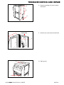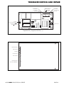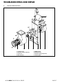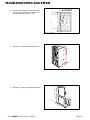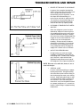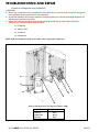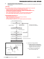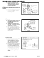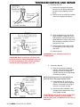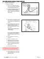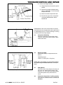
1
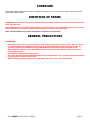
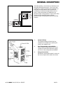
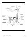
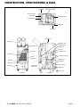
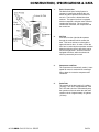
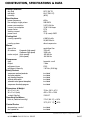
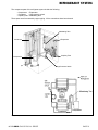
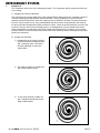
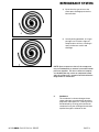
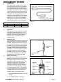
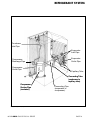
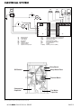
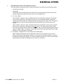
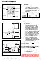
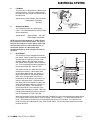
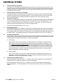
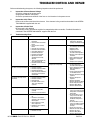
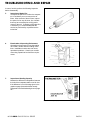
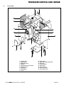
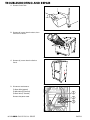
SERVICE M A N U A L CLASSIC PLUS 26 DENSO SALES CALIFORNIA, INC. REGISTERED TO ISO 9002 FILE NO. A5537 (800) 264-9573 www.movincool.com © 2000 DENSO SALES CALIFORNIA, INC. All rights reserved. This book may not be reproduced or copied, in whole or in part, without the written permission of the publisher. DENSO SALES CALIFORNIA, INC. reserves the right to make changes without prior notice. MovinCool is a registerd trademark of DENSO CORPORATION. DSCA P/N: LA990009-0549-E FOREWORD This manual has been published to service the MovinCool Classic Plus 26. Please use this service manual only when servicing the Classic Plus 26. DEFINITION OF TERMS WARNING: Describes precautions that should be observed in order to prevent injury to the user during installation or unit operation. CAUTION: Describes precautions that should be observed in order to prevent damage to the unit or its components, which may occur during installation or unit operation if sufficient care is not taken. NOTE: Provides additional information that facilitates installation or unit operation. GENERAL PRECAUTIONS WARNINGS: • • • • • All electrical work if necessary, should only be performed by qualified electrical personnel. Repair to electrical components by non-certified technicians may result in personal injury and/or damage to the unit. All electrical components replaced must be genuine MovinCool, purchased from an authorized reseller. When handling refrigerant, always wear proper eye protection and do not allow the refrigerant to come in contact with your skin. Do not expose refrigerant to an open flame. The proper electrical outlet for MovinCool units must be equipped with a “UL” approved ground-fault breaker to prevent electrical shock from the unit. When brazing any tubing, always wear eye protection and work only in a well ventilated area. MOVINCOOL CLASSIC PLUS 26 SERVICE PAGE 2 GENERAL DESCRIPTION Generally speaking, conventional air conditioners cool the entire enclosed environment. They act as “heat exchangers”, requiring an interior unit (evaporator) to blow cool air into the interior and an exterior unit (condenser) to exhaust exchanged heat to the outdoors. Unlike conventional air conditioners, the MovinCool Spot Cooling System is a spot cooler which directs cool air to particular areas or objects. MovinCool Spot Cooling Systems have the following features: CONDENSER (OUTDOOR UNIT) EVAPORATOR (INDOOR UNIT) Conventional Air Conditioner 1. Compact Design The innovative design of MovinCool has resulted in one compact unit, replacing the need for two separate units. 2. Easy Transportation and Installation With the whole cooling system built into one compact unit, MovinCool requires no piping and can be easily transported and installed. 3. Energy Conservation MovinCool is economical because it cools only the area or objects which need to be cooled. Air Flow of MovinCool Spot Cooling System MOVINCOOL CLASSIC PLUS 26 SERVICE PAGE 3 Construction of Classic Plus 26 MOVINCOOL CLASSIC PLUS 26 SERVICE PAGE 4 CONSTRUCTION, SPECIFICATIONS & DATA Side Panel High Pressure Switch Blower Housing (Evaporator) Exhaust Air Outlet Evaporator Fan Condenser Side Panel Upper Panel Cool Air Duct Modulating Tank Blower Housing (Condenser) Control Panel Fan Motor Front Panel Condenser Fan Evaporator Air Filter (Condenser) Air Filter (Evaporator) Capillary Tube Control Box Drain Pan Drain Tube Service Panel Base Panel Drain Switch Rear Panel Power Cord Drain Tank Caster Compressor Construction Diagram of Classic Plus 26 MOVINCOOL CLASSIC PLUS 26 SERVICE PAGE 5 CONSTRUCTION, SPECIFICATIONS & DATA 1. Basic Construction The MovinCool Spot Cooling System is compact in construction because the condenser and the evaporator are enclosed in one unit. The interior is divided into three sections. The upper front face is equipped with the evaporator, while the lower front face contains the drain tank. The rear section contains the condenser, the compressor and the control box. 2. Air Flow Air drawn from the right side face passes through the condenser which extracts the heat. This hot air is blown out through the upper exhaust air duct. Air taken in from the front face is cooled by the evaporator and then blown through the cool air duct which can be turned in any direction. All the air inlets are equipped with filters, while the exhaust air outlet is protected by wire mesh. 3. Compressor and Fans The compressor is hermetically sealed. A twospeed fan motor is used with two centrifugal fans to draw air across the evaporator and condenser. 4. Drain Tank The capacity of the drain tank is 5.0 gallons (19 liters). The unit is equipped with a "Tank Full" LED and a device to automatically stop the operation of the unit when the drain tank reaches a level of approximately 4.0 gallons (15 liters). Air Flow MOVINCOOL CLASSIC PLUS 26 SERVICE PAGE 6 CONSTRUCTION, SPECIFICATIONS & DATA Rating Conditions dry bulb wet bulb humidity Specifications power frequency line voltage, single phase power consumption current consumption power factor starting current power cord Cooling Unit cooling capability cooling system Blower type of fan Evaporator (high speed) air volume: Condenser (high speed) motor output (high speed) (low speed) Compressor type output refrigerant type refrigerant capacity Safety Devices compressor overload protector fan motor protector anti-freezing thermistor full drain tank switch automatic restart (power interruption) compressor time delay program Dimensions & Weight W x D x H (in.) W x D x H (mm) weight (lbs/kg) Operating Conditions inlet air (relative humidity) Control Device temperature control two speed fan Specifications MOVINCOOL CLASSIC PLUS 26 SERVICE 95 oF (35 oC) 83 oF (28.3 oC) (60%) 60Hz 208/230V 3.37/3.24 Kw 16.8/14.6 Amps 97% 62A 12 (3-core) AWG 6,500 Kcal/hr 26,000 Btu/hr direct expansion centrifugal fan 708 cfm 1680 cfm .59/.63 Kw .54/.56 Kw hermetic scroll 1.6kw R-22 1.87 lbs. (0.85 kg) included included included included included included 19.4 x 28.7 x 47.2 492 x 730 x 1200 235/107 113 oF (45 oC), < 50% 70oF (21.1 oC), > 50% included included Specifications are subject to change without notice. PAGE 7 CONSTRUCTION, SPECIFICATIONS & DATA 10.60 2.62 3.70 10.80 3.84 7.28 29.24 23.76 48.0 44.12 3.88 12.56 16.80 19.60 2.80 21.88 28.40 3.72 Exterior Dimensions MOVINCOOL CLASSIC PLUS 26 SERVICE PAGE 8 CONSTRUCTION, SPECIFICATIONS & DATA Cool Air Temperature Difference Curve (high speed only) Cooling Capability Curve (high speed only) Power Consumption Curve (high speed only) MOVINCOOL CLASSIC PLUS 26 SERVICE PAGE 9 REFRIGERANT SYSTEM The component parts of the refrigerant system include the following: • Compressor • Evaporator • Condenser • High pressure switch • Capillary tube • Modulating tank These parts are all connected by copper piping. All the connections have been brazed. Modulating Tank Condenser Compressor Evaporator Capillary Tube High Pressure Switch Refrigerant System MOVINCOOL CLASSIC PLUS 26 SERVICE PAGE 10 REFRIGERANT SYSTEM 1. Compressor The compressor used for the unit is hermetically sealed. The compressor and the compressor motor are in one casing. A. Compressor Theory of Operation The scroll utilizes an involute spiral which, when matched with a mating scroll form, generates a series of crescent-shaped gas pockets between the two members. During compression, one scroll remains stationary (fixed scroll) while the other form (orbiting scroll) is allowed to orbit (but not rotate) around the first form. As this motion occurs, the pockets between the two forms are slowly pushed to the center of the two scrolls while simultaneously being reduced in volume. When the pocket reaches the center of the scroll form, the gas, which is now at a high pressure, is discharged out of a port located at the center. During compression, several pockets are being compressed simultaneously, resulting in a very smooth process. Both the suction process (outer portion of the scroll members) and the discharge process (inner portion) are continuous. B. Compressor Operation 1) Compression in the scroll is created by the interaction of an orbiting spiral and a stationary spiral. Gas enters the outer openings as one of the spirals orbits. 2) The open passages are sealed off as gas is drawn into the spiral. 3) As the spiral continues to orbit, the gas is compressed into two increasingly smaller pockets. MOVINCOOL CLASSIC PLUS 26 SERVICE PAGE 11 REFRIGERANT SYSTEM 4) By the time the gas arrives at the center port, discharge pressure has been reached. 5) Actually, during operation, all six gas passages are in various stages of compression at all times, resulting in nearly continuous suction and discharge. NOTE: Upon compressor shut-off, the compressor may run backward for a moment or two until internal pressures equalize. This has no effect on compressor durability but may cause an unexpected sound after the compressor is turned off and should not be diagnosed as a malfunction. 2. MOVINCOOL CLASSIC PLUS 26 SERVICE Condenser The condenser is a heat exchanger whose copper tubes are covered with thin aluminum projections called spine fins. Heat is given off and absorbed by air being pulled across the condenser fins by the centrifugal fan and then expelled through the exhaust air duct. PAGE 12 REFRIGERANT SYSTEM 3. Capillary Tube The capillary tube is a long thin tube and its line flow resistance serves as an expansion valve. The length and the inner diameter of the capillary tube are determined according to the capacity of refrigeration system, operating conditions and the amount of refrigerant. The capillary tube causes the high pressure, high temperature liquid refrigerant sent from the condenser to expand rapidly as the refrigerant is sprayed out through the fixed orifice in the capillary tube. As a result, the temperature and state of the refrigerant become low and mist-like, and therefore it evaporates easily. Capillary Tube Qty 1 Capillary Tube Dimensions Purpose of Use I.D. (mm) Length (mm) For cooling ∅1.5 ± 0.05 540 4. Evaporator The evaporator, like the condenser, is a heat exchanger covered with spine fins. Heat is removed from the air being pulled across the evaporator by the centrifugal fan and the resulting cool air is expelled through the cooling air ducts. 5. Modulating Tank The modulating tank consists of a copper pipe and tank sections, each being separated from the other. The pipe connects to the evaporator outlet at one end and to the compressor at the other; the tank connects to the evaporator inlet. The modulating tank is covered with insulation to reduce thermal effects of ambient temperature. It varies the quantity of refrigerant in the refrigerating cycle for optimum operating condition; it stores part of refrigerant under light load and delivers additional refrigerant to the cycle under heavy load. 6. High Pressure Switch The high pressure switch prevents the condenser and compressor from being damaged by excessively high pressure in the high pressure line of the refrigeration cycle. The switch is normally closed. The snap disk responds to variations in pressure and, if pressure is abnormally high, the snap disk moves down to push the pin down, causing the internal contacts to open. This interrupts the ground signal at the Control Board (J104 connector) which turns the compressor off. Modulating Tank Possible causes of this trouble include: A. The condenser air filter is dirty, restricting air flow. High Pressure Switch B) The condenser blower is defective. MOVINCOOL CLASSIC PLUS 26 SERVICE PAGE 13 REFRIGERANT SYSTEM Condenser Inlet Pipe Evaporator Inlet Pipe Evaporator Outlet Pipe Compressor Discharge Pipe Compressor Outlet Pipe Capillary Tube Connecting Tube (condenser to capillary tube) Compressor Suction Pipe (insulated) Connecting Pipe (evaperator to compressor) Refrigerant System Piping MOVINCOOL CLASSIC PLUS 26 SERVICE PAGE 14 ELECTRICAL SYSTEM AP RTH THS DS 3 G T R HPRS 1 CC 1 2 2 TB MC IOLC G G CF 1 2 L0 MF HI J4 IOLF J101 J102 J103 J104 J8 (AUX1) J5 G J6 J9 J201 J2 J1 J3 AP TB CB RB MF MC CF CC Attachment Plug Terminal Block Control Board Relay Board Fan Motor Compressor Motor Capacitor for Fan Capacitor for Compressor RB IOLC IOLF HPRS DS THS RTH G J8 (AUX1) CB Internal Overload Protector of Compressor Internal Overload Protector of Fan Motor High Pressure Switch Full Drain Warning Switch Freeze Protection Thermistor Room Thermistor Ground Auxiliary Connector (CPK-4) Relay Board DIP Switch Relay Board Fuse Terminal Block Compressor Capacitor Fan Motor Capacitor Electrical System and Control Box for Classic Plus 26 MOVINCOOL CLASSIC PLUS 26 SERVICE PAGE 15 ELECTRICAL SYSTEM 1. Basic Operation of Classic Plus 26 Electrical Circuit There are two basic components used to control the operation of the Classic Plus 26 Electrical System: • Control Panel Assembly • Control Box The Control Panel Assembly contains the Control Panel, Control Board (with inputs for the freeze and room temperature thermistors), drain switch, and a microprocessor. A. Fan “Only” Mode Low Fan Mode - When the “Low” Fan Mode button on the control panel is pressed, the microprocessor turns on the button’s LED and activates the Fan “On” Relay (Relay Board), sending line voltage (208/230 VAC) to the N.C. (Normally Closed) contacts of the fan “mode” relay. This output is connected to the J5 terminal (relay board) where the LOW SPEED wire of the fan motor is connected. High Fan Mode – When the “High” Fan Mode button on the control panel is pressed, the microprocessor turns on the button’s LED and activates both the Fan “On” Relay and Fan “Mode” Relay. This sends line voltage (208/230 VAC) from the Fan “On” Relay to the N.O. (Normally Open) contacts of the Fan “Mode” Relay. This output is connected to the J6 terminal (Relay Board) where the HIGH SPEED wire of the Fan Motor is connected. B. Cool Mode - In Addition to Fan “Only” Mode (as described above) When the Cool On/Off button on the control panel is pressed, the microprocessor turns on the button’s LED and if the Temperature Set Point is less than the current room temperature, activates the Compressor Relay (Relay Board). This sends line voltage (208/230 VAC) to the J4 terminal (Relay Board) where the wire from the Compressor wire harness is connected. MOVINCOOL CLASSIC PLUS 26 SERVICE PAGE 16 ELECTRICAL SYSTEM 2. Control Box A. Capacitors Relay Board Relay Board Fuse DIP Switch Terminal Block Compressor Capacitor Fan Motor Capacitor The capacitors are used to temporarily boost the power output available to the fan motor and the compressor at start-up. The specifications of each capacitor are listed below: CAPACITOR APPLICATION VOLTAGE RATING CAPACITANCE (µf) Fan Motor Compressor 440 370 12.5 40 Control Box B. Relay Board J9 C STOP DIP Switch Temperature Scale Display Switch ˚C ˚F Fan Mode Control Switch STOP OPERATE S1 F OPERATE The Relay Board receives signals and outputs from the control board that contains a microprocessor. The relay board contains the compressor, fan on and fan mode (speed) relays. It also contains a step-down transformer that converts the line voltage (208/230 VAC) to 12 volts. This is then converted from AC to DC and used for relay coil activation. The 12V (DC) power is sent to the Control Panel Assembly where it is further reduced to 5 volts for the system logic. DIP Switch Relay Board Fuse The relay board also contains the DIPSwitch. The DIP-Switch is used to change the Fan Mode operation from Stop to Operate and change the Set Point temperature display from ˚F to ˚C. NOTE: The relay board must be serviced as a complete assembly. It has only one serviceable component, the fuse. (a) Relay Board Fuse NOTE: The relay board fuse is the only serviceable component on the relay board assembly. This fuse provides protection against damage to the step-down transformer. It must be replaced with the exact type of fuse or an equivalent. Fuse Specifications: 2/10A 250V Relay Board MOVINCOOL CLASSIC PLUS 26 SERVICE CAUTION: Failure to use the exact type of fuse could result in damage to the unit and/or to components. It will also void the warranty of the unit. PAGE 17 ELECTRICAL SYSTEM 3. Fan Motor The fan motor is a single phase, induction type two-speed motor. The motor rotates fans on the evaporator side and the condenser side at the same time. Specifications: Rated Voltage: 230 volts 60 Hz Rated Output: 559 watts 355 watts 4. Compressor Motor The compressor motor is a single phase motor. It is contained within the same housing as the compressor. Specifications: CF1 (White) CF2 (Brown/White) J5 Low (Red) J6 High (Black) Ground (Green/Yellow) Fan Motor Rated Voltage: 230 volts Rated Output:1600 Watts NOTE: An internal overload relay is used to protect the compressor motor and fan motor. This relay is built into the compressor motor and fan motor and will interrupt the flow of current when there is an overcurrent situation or if abnormally high temperature builds up in the compressor motor or fan motor. 5. Drain Switch The Classic Plus 26 is equipped with a drain tank switch. When the drain tank accumulates approximately 4.0 gallons (15 liters) of condensate (water) in the drain tank, the drain tank switch sends a signal to the microprocessor. The microprocessor stops all operation of the unit and flashes the "Tank Full" LED. TOP OF BASE PLATE DRAIN SWITCH To J103 DRAIN PAN NC DS2 This system utilizes a .1 AMP, 250 VAC microswitch for this function. When drain water accumulates approximately 4.0 gallons (15 liters) in the drain tank, the drain tank base plate, which is supported at its fulcrum, is pushed down in the direction of the arrow as shown in the figure below. When the drain tank base plate is forced down, the top of the drain tank base plate opens the contacts (1) – (2) of the micro switch. This causes the ground signal at the J103 connector of the control panel assembly to go open. When the microprocessor detects this event, it turns the unit off and flashes the "Tank Full" LED. EVAPORATOR 2 1 DRAIN TUBE DS1 C DRAIN TANK DRAIN WATER SPRING FULCRUM BASE BASE PLATE Operation of Drain Switch When the drain tank is removed (or the drain tank is emptied), the top of the drain tank base plate returns to its original position by the tension of the coil spring. Then contacts (1) – (2) of the drain tank switch close. This provides a ground to the microprocessor through the J103 connector. To re-start the unit, press one of the fan mode buttons or the “Cool On/Off” button. The unit will return to the previous Temperature Set Point. MOVINCOOL CLASSIC PLUS 26 SERVICE PAGE 18 ELECTRICAL SYSTEM 6. Condensate Pump Kit (optional) The Classic Plus 26 model comes standard with a drain tank, which collects the water that forms on the evaporator during normal cooling operation. If the unit is required to operate continuously without periodic emptying of this tank, a condensate pump may be needed. A condensate pump kit (CPK-4) is available for the Classic Plus 26 model. 7. Automatic Restart After Power Interruption The program within the microprocessor of the Classic Plus 26 contains a feature that will automatically restart the unit after power is lost and then regained. The unit also has memory in order to return itself back to the operating mode (including temperature set point) it was in prior to the loss of power. 8. Compressor Protection There is a Time Delay program within the microprocessor. This prevents a heavy load from being applied on the Compressor Motor when restarting the unit (Cool Mode) after a very short period of time. This “delay” is in effect any time when the compressor is turned on by either the “Cool On/Off” button, temperature set point (thermostatic control), or power interruption restart. Time Delay Program Specifications: 120 ± 10 sec. 9. Temperature Control The compressor operation (Cool Mode) is controlled by the microprocessor which receives input signals from the room temperature thermistor (evaporator inlet air) and the setting of the Temperature Set Point. The Temperature Set Point (desired room temperature) can be adjusted by pressing the ▲ / ▼ buttons on the Control Panel. The adjustment range of the Temperature Set point is 70˚F to 95˚F (21˚C to 35˚C). 10. Fan Mode Control Switch The fan motor operation is controlled by relays on the relay board through a microprocessor in the control panel assembly. The fan program in the microprocessor can be changed by a DIP-Switch on the left side of the Relay Board located in the Control Box. There are two settings: A. Cool to Stop When the DIP-Switch is set to the down or “Stop” position, the microprocessor controls the fan motor using the same room temperature thermistor that it uses to control the compressor. In this case, both the fan and the compressor stop when the microprocessor receives a sufficiently low intake air (room temperature) signal from the thermistor (equal to or less than the set point). When the temperature increases (exceeds the set point) the microprocessor will restart the fan and compressor automatically. However, if the unit has been off for less than 130 sec., the fan will start before the compressor (time delay program). B. Cool to Operate When the DIP-Switch is set in the up or “Operate” position, the microprocessor controls the fan operation using control panel inputs only. The fan will operate continuously during Fan Only and Cool Modes. (This is the “Factory Default” setting.) 11. Temperature Scale Display Switch When the DIP Switch is set in the down or “˚C” position, the Set Point Temperature will be displayed in degrees Celsius. The LED that indicates ˚C will also be illuminated. When the DIP Switch is set in the up or “˚F” position, the Set Point Temperature will be displayed in degrees Fahrenheit.. The LED that indicates ˚F will also be illuminated. (This is the “Factory Default” setting.) MOVINCOOL CLASSIC PLUS 26 SERVICE PAGE 19 TROUBLESHOOTING AND REPAIR Before troubleshooting the system, the following inspection should be performed. 1. Inspection of Power Source Voltage Check the voltage of the power source. Single phase 208/230 volts (60Hz) Check the operation and condition of the fuse or circuit breaker in the power source. 2. Inspection of Air Filters Remove the air filters and check the element. If the element is dirty, wash it as described in the OPERATION MANUAL supplied with the unit. 3. Inspection of Drain Tank Be sure tank is fully drained. The following chart is provided as a guide for categorized problem remedies. Detailed information is contained in the OPERATION MANUAL supplied with the unit. 4. Troubleshooting Chart Trouble Probable Cause Trouble Probable Cause Unit does not operate at all • Check for Power at Receptacle • Check for Power at Terminal Board • Check for Power at Relay Board • Check all wire connections • Defective Drain Tank Switch • Check Relay Board Fuse • Defective Relay Board • Defective Control Board • High Pressure Switch activated, disconnected, defective • Jumper on Relay Board (J8) not installed correctly • Defective Condensate Pump (optional) Insufficient Air Flow (cont’d) • Clogged spine fins or Evaporator or Condenser (running unit without filter(s)) Insufficient Cooling • Environmental conditions exceed design specifications • Clogged air filter • Clogged spine fins • Set point temperature exceeds room temperature • Defective room temperature thermistor • Leak in refrigerant system • Restriction in refrigerant system • Compressor not operating Compressor not operating • Set point temperature exceeds room temperature • Unit is operating in Fan Only Mode (Cool Mode not activated) • Jumper on Relay Board (J8) not installed correctly • Defective Condensate Pump (optional) • Defective Compressor Capacitor • Defective Thermistor • Defective Compressor Motor • Check wiring connections • Defective Relay Board • Defective Control Board Fan Motor not operating • Fan mode switch is set to “Stop” and current Set Point Temperature exceeds Room Temperature • Fan mode switch is set to “Stop” and unit has been equipped with optional Condensate Pump that is defective • Fan mode switch is set to “Stop” and Jumper on Relay Board (J8) is not installed correctly • Check wire connections • Defective fan motor capacitor • Defective fan motor • Defective Relay Board • Defective Control Board Unit starts, but stops immediately • • • • Defective Fan Motor Defective Compressor Motor Defective Relay Board Room and Freeze Thermistor connectors are reversed on control board Unit operates, but stops after a few minutes • • • • Defective Compressor Motor Defective Fan Motor Drain Tank Full Fan Mode Switch is set to “Stop” and compressor cycled off Water leakage from the unit • Drain Tank not installed • Drain Tank is defective (cracked) • Drain Pan hole is obstructed Abnormal noise and/or shaking • Loose Compressor mounting nut • Deformed or worn rubber grommet on the compressor mounting bolt • Internal interference with other components • Damaged or out of balance fan and scroll Insufficient Air Flow • Fan mode switch on “Low” • Defective fan motor MOVINCOOL CLASSIC PLUS 26 SERVICE PAGE 20 TROUBLESHOOTING AND REPAIR In case of trouble, perform the following inspection before disassembly. 5. Inspection of Spine Fins To inspect the spine fins of either the evaporator or condenser you must remove the air filters. After removal of the air filters, inspect the spine fins for any dirt, dust, lint, or debris that may have caused poor cooling performance of the unit. If cleaning of the spine fins is necessary, it is recommended that this service be performed by a qualified service technician. Spine Fins 6. Examination of Operating Environment Operating environments will vary depending on location, climate and surrounding conditions. Installation location also can cause operational problems. Consult your reseller concerning operational environment requirements. Operating Environment 7. Inspection of Cooling Capacity Measure the difference in temperature between the inlet of the evaporator and the cool air duct. If the difference is out of the range given in the graphs on page 8 proceed with the remedy suggested in the troubleshooting chart on page 20. Inspection of Cooling Capacity MOVINCOOL CLASSIC PLUS 26 SERVICE PAGE 21 TROUBLESHOOTING AND REPAIR 8. Disassembly 2 1 4 10 3 4 16 5 11 6 12 17 7 13 8 15 9 14 9 1. 2. 3. 4. 5. 6. 7. 8. 9. Control panel Upper panel Right side panel Air filter Blower housing (condenser) Condenser fan Rear panel Drain Switch Caster 10. 11. 12. 13. 14. 15. 16. 17. Front panel Blower housing (evaporator) Drain pan Left side panel Drain tank Service panel Room thermistor Freeze thermistor Disassembly MOVINCOOL CLASSIC PLUS 26 SERVICE PAGE 22 TROUBLESHOOTING AND REPAIR A. Remove Drain Tank. Removal of Drain Tank B. Remove (8) screws from the ducts, then remove the 2-ducts. Removal of Duct Screws and Ducts C. Remove (4) screws from the Service Panel. 4 Removal of Service Panel Screws D. Disconnect and remove: ➀ Green Wire (ground) ➁ White Wire (R-Terminal) ➂ Black Wire (T-Terminal) ➀ ➁ ➂ Remove the power cord. Removal of Power Cord Screws MOVINCOOL CLASSIC PLUS 26 SERVICE PAGE 23 TROUBLESHOOTING AND REPAIR E. Remove remaining (13) screws and the back panel. 4 3 3 3 Removal of Back Panel Screws 4 (backside) 4 F. Remove (14) screws from the Top Panel. 2 Removal of Top Panel Screws 2 G. Top Panel (4). 2 Removal of Top Panel MOVINCOOL CLASSIC PLUS 26 SERVICE PAGE 24 TROUBLESHOOTING AND REPAIR AP RTH THS DS 3 G T R HPRS 1 CC 1 2 2 TB MC IOLC G G CF 1 2 L0 MF HI J4 IOLF J101 J102 J103 J104 J8 (AUX1) J5 G J6 J9 J201 J2 J1 J3 AP TB CB RB MF MC CF CC Attachment Plug Terminal Block Control Board Relay Board Fan Motor Compressor Motor Capacitor for Fan Capacitor for Compressor RB IOLC IOLF HPRS DS THS RTH G J8 (AUX1) CB Internal Overload Protector of Compressor Internal Overload Protector of Fan Motor High Pressure Switch Full Drain Warning Switch Freeze Protection Thermistor Room Thermistor Ground Auxiliary Connector (CPK-4) Relay Board DIP Switch Relay Board Fuse Terminal Block Compressor Capacitor Fan Motor Capacitor Removal of Electrical Parts in the Control Box MOVINCOOL CLASSIC PLUS 26 SERVICE PAGE 25 TROUBLESHOOTING AND REPAIR To Terminal Block (R-Terminal) Pin #2 Compressor Overload Relay To Fan Motor (Low Speed) J4 J5 J6 J2 J3 S1 C STOP J9 Relay Board Fuse J8 DIP Switch Temperature Scale Display Switch ˚C ˚F Fan Mode Control Switch STOP OPERATE Relay Board Ground (not used) F1 F OPERATE J1 To Terminal Block (T-Terminal) To Fan Motor (High Speed) Main Wiring Harness Relay Board to Control Panel Jumper or 2-Pin Connector of (optional) Condensate Pump Kit - CPK-4 Drain Tank Switch NOT USED Freeze Thermistor Room Thermistor Main Wiring Harness (Control Panel to Relay Board) J201 High Pressure Switch J101 J102 J106 J103 J104 Connections to Relay Board Connections to Control Board MOVINCOOL CLASSIC PLUS 26 SERVICE PAGE 26 TROUBLESHOOTING AND REPAIR 9. Removal of Electrical Parts ➇ ➀ 1. 2. 3. 4. ➁ ➂ Condenser fan Blower housing (condenser) Fan motor Motor bracket ➄ ➃ 5. 6. 7. 8. ➅ ➆ Middle Frame Evaporator fan Blower housing (evaporator) Air flow guide Disassembly of Blower MOVINCOOL CLASSIC PLUS 26 SERVICE PAGE 27 TROUBLESHOOTING AND REPAIR 10. Removal of Blower Assembly A. Loosen the set screw using an allen wrench and then remove the centrifugal fan. Removal of Centrifugal Fan B. Remove the two (2) nuts on the inside of the housing in the locations shown. A - NUT Removal of Blower Housing C. Remove two nuts and two screws as depicted. Then remove the motor bracket together with the fan motor. A - NUT B - SCREW Removal of Fan Motor Assembly MOVINCOOL CLASSIC PLUS 26 SERVICE PAGE 28 TROUBLESHOOTING AND REPAIR D. Remove the centrifugal fan by loosening the set screw on the shaft. Remove the fan motor, by loosening “A” nuts. Removal of Fan Motor E. Remove (7) screws from Left Side Panel. 4 3 Removal of Left Side Panel Screws F. 3 Remove (7) screws from Right Side Panel. 3 Removal of Right Side Panel Screws MOVINCOOL CLASSIC PLUS 26 SERVICE PAGE 29 TROUBLESHOOTING AND REPAIR G. Remove (2) screws from Control Panel Assembly Right Stay. Removal of Right Stay Screws H. Remove (2) screws from Control Panel Assembly Left Stay. Removal of Left Stay Screws I. Disconnect the following connectors from the control board: (1) Wire Harness, Relay Board to Control Board J201 (10-pin) (2) Drain Tank Switch J103 (2-pin) (3) Room Temperature Thermistor J101 (2-pin) (4) Freeze Thermistor J102 (2-pin) (5) High Pressure Switch J104 (2-Pin) Removal of Control Panel Assembly MOVINCOOL CLASSIC PLUS 26 SERVICE NOTE: Mark each of the 2-pin connectors with a different color marker to ensure the correct orientation when they are re-connected. PAGE 30 TROUBLESHOOTING AND REPAIR J. Remove the five (5) screws from the control board on the control panel assembly. Remove the control board. Removal of Control Board 11. Inspection of Capacitor (Fan Motor and Compressor) Ohmeter Method – Set the ohmeter to the 100K Ω range. Place the two probes against the two terminals of the capacitor. At first, the ohmeter should indicate 0Ω, then the reading should gradually increase towards infinity (∞). This indicates that the capacitor is charging. If the reading indicates infinity right away (shorted) or the ohmeter fails to move from 0Ω (open), replace the capacitor. 12. Capacitance Tester Method Using a capacitance tester and the chart on page 15, test the capacitor for the value indicated. If the value tested is not within 10% of indicated capacitance, replace the capacitor. Inspection of Capacitor WARNING: Properly discharge the capacitor(s) before testing and after testing has been completed. Failure to do so could cause damage to test equipment or the unit and/or result in personal injury (electrical shock) or death. MOVINCOOL CLASSIC PLUS 26 SERVICE PAGE 31 TROUBLESHOOTING AND REPAIR TOP OF BASE PLATE 13. Inspection of Drain Switch Check for continuity between terminals 1 and 2. Continuity should exist. With switch depressed, continuity should not exist between terminals 1 and 2. If continuity is not as specified above, replace the switch. 14. Inspection of Fan Motor Measure resistance across the terminals of the fan motor. DRAIN SWITCH To J103 NC DS2 2 1 DS1 C Inspection of Drain Switch Terminals (at 77˚F (25˚C)) J6 - CF1 Approx. 6.8Ω J5 - CF1 Approx. 10.5Ω CF1 - CF2 Approx. 19.0Ω CF1 (White) CF2 (Brown/White) J5 Low (Red) J6 High (Black) If the measured resistance is not equal to these standard values, replace the fan motor. Ground (Green/Yellow) Inspection of Fan Motor 15. Inspection of Compressor Motor Measure resistance across the terminals of the compressor motor. Terminals (at 77˚F (25˚C )) R-C C-S S-R Inspection of Compressor Motor MOVINCOOL CLASSIC PLUS 26 SERVICE Approx. 0.94 Approx. 1.96 Approx. 2.90 If the measured resistance is not equal to these standard values, replace the compressor. The compressor has a built-in overload relay. The overload relay should be operational if the above resistance is obtained under normal temperature. PAGE 32 TROUBLESHOOTING AND REPAIR 16. Inspection of High Pressure Switch Check for continuity across both terminals of the high pressure switch or the J104 connector. With pressure equalized when the unit is stopped, there should be continuity across both terminals and the J104 connector. If there is no continuity (open circuit), replace the high pressure switch. Specifications: Cut off pressure - 29.5kg/cm2G (420 PSIG) Reset pressure - 20.5kg/cm2G (291 PSIG) 17. Inspection of Wiring Connection Refer to the Wiring Diagrams (pg. 40) and check for connection of each wire. 18. Inspection of Thermistor(s) Using an Ohmeter, check the resistance value across the 2-Pin connector. At normal temperature (77˚F, 25˚C) either thermistor (Room or Freeze) should measure approx. 10,000 or 10k ohms. 19. Inspection In most cases, the probable cause for insufficient cooling is a clogged system, leakage or an incorrect amount of refrigerant. In such cases, inspect the system according to the following procedure. A. Inspection of Clogged System Check the component parts of the refrigerant system, including piping, that could be clogged with refrigerant. If clogged with refrigerant, only the clogged part is frosted partially. In such a case, change the part in question. B. Inspection of Refrigerant Leak Carefully check all connections, and each component for leaks whenever the refrigerant system is installed or repaired. Use an electronic gas leak tester to inspect the system. C. Insufficient Refrigerant In case the unit is judged to be deficient in cooling capacity, be sure to perform the inspections in A. and B. to confirm the cause of trouble. After that, charge the system with refrigerant to the specified amount. 20. Repair of Refrigerant System In case there is a leak, obstruction, or trouble in the refrigerant system of the Spot Cooling System, replace or repair the part in question. After replacing any component all connections must be brazed. A. Proper Brazing Techniques It is desirable to use a slightly reducing flame. Oxyacetylene is commonly used since it is easy to judge and adjust the condition of the flame. Unlike gas welding, a secondary flame is used for brazing. It is necessary to preheat the base metal properly depending on the shape, size or thermal conductivity of the brazed fitting. The most important point in flame brazing is to bring the whole brazed fitting to a proper brazing temperature. Care should be taken to not cause overflow of brazing filler metal, oxidization of brazing filler metal, or deterioration due to the overheating of flux. MOVINCOOL CLASSIC PLUS 26 SERVICE PAGE 33 TROUBLESHOOTING AND REPAIR • BRAZED FITTING AND ITS CLEARANCE In general, the strength of brazing filler metal is lower than that of the base metal. So, the shape and clearance of the brazed fitting are quite important. As for the shape of the brazed fitting, it is necessary to maximize its adhesive area. The clearance of the brazed fitting must be minimized to facilitate brazing filler metal to flow into it by capillary action. • Brazed Fitting and Clearance CLEANING OF BRAZING FILLER METAL AND PIPE When the refrigerant system has been opened up, exposure to heat may have caused brazing filler metal to stick to the inside and outside of the pipe. Brazing filler metal may also be compounded with oxygen in the air to form oxide film. Fats and oils may stick to the pipe from handling. All these factors will reduce effectiveness of brazing. It is necessary to eliminate excess brazing filler metal using sand paper and by cleaning thoroughly with a solvent such as Trichlene. • USE OF DRY NITROGEN GAS During brazing, the inside of the pipe undergoes an oxidative reaction due to the brazing flame. Introduce dry nitrogen gas (1 liter/min.; adjust with the flow regulator) through the pinch-off tube of the refrigerant cycle to prevent oxidation. Vertical Down Joint NOTE: Take care not to allow dirt, water, oil, etc. to enter into the pipe • Vertical Up Joint MOVINCOOL CLASSIC PLUS 26 SERVICE VERTICAL JOINT Heat the whole brazed fitting to a proper brazing temperature. Bring the brazing filler metal into contact with the fitting so that the brazing filler metal starts flowing by itself. Stop heating the fitting as soon as the brazing filler metal has flown into the clearance. Since the brazing filler metal flows easily into the portion heated to a proper temperature, it is essential to keep the whole fitting at a proper brazing temperature. PAGE 34 TROUBLESHOOTING AND REPAIR B. Removal of Refrigeration Cycle Components CAUTION: 1. Before any refrigeration cycle component can be replaced, it is necessary to recover the refrigerant using standard recovery procedures and equipment. 2. To prevent oxidation, dry nitrogen should be conducted (flow rate 1 liter/min) through the pinch-off tube during any brazing operation. 3. During any component replacement involving brazing, shield nearby parts with a steel plate, asbestos, etc., to protect them from the flame. (1) Evaporator (2) Capillary tube (3) Condenser (4) Compressor NOTE: Hold the compressor body, not the tube, when carrying the compressor. A C D F E B Removal of Refrigerant Cycle Components (Refer to 20.B.) PART REPLACED Compressor Condenser Capillary tube Evaporator DISCONNECT AT: A&B A&C D&E E&F Refrigeration Cycle Components MOVINCOOL CLASSIC PLUS 26 SERVICE PAGE 35 TROUBLESHOOTING AND REPAIR 21. Charging the System with R-22 Refrigerant Always ensure that the refrigerant system has been properly evacuated before charging with the specified amount of R-22. WARNING: When handling refrigerant (R-22), the following precautions should always be observed: • Always wear proper eye protection while handling refrigerant. • Maintain the temperature of the refrigerant container below 40˚C (104˚F). • Perform repairs in a properly ventilated area. (Never in an enclosed environment.) • Do not expose refrigerant to an open flame. • Never smoke while performing repairs, especially when handling refrigerant. • Be careful the liquid refrigerant does not come in contact with the skin. If liquid refrigerant strikes eye or skin: • Do not rub the eye or the skin. • Splash large quantities of cool water on the eye or the skin. • Apply clean petroleum jelly to the skin. • Go immediately to a physician or to a hospital for professional treatment. STEP 1. CONNECT MANUFOLD GAUGE STEP 2. EVACUATE THE SYSTEM 750 mmHg (29.55 inHg) OR MORE OF VACUUM 15 MINUTES OR MORE WHEN LEAK IS FOUND, REPAIR THE CONNECTION OR COMPONENTS STOP EVACUATING THE SYSTEM LEAVE FOR FIVE MINUTES CHECK THE VACUUM STEP 3. CONNECT TO REFRIGERANT SOURCE STEP 4. TEST THE SYSTEM FOR LEAKS STEP 5. CHARGE THE SYSTEM WITH R-22* * SEE SPECIFICATIONS ON PAGE 6 STEP 6. REMOVE MANIFOLD GAUGE A. Connection of Gauge Manifold (1) Properly remove the crushed end of the pinch-off tube at the high pressure side and the low pressure side of the refrigerant cycle with a pipe cutter. (2) Fit the process tube fitting to the pinch-off tube on both sides. Mounting of Process Tube Fitting MOVINCOOL CLASSIC PLUS 26 SERVICE PAGE 36 TROUBLESHOOTING AND REPAIR (3) Connect the charging hoses (red high pressure side, blue - low pressure side) of the gauge manifold to the process tube fittings. NOTE: Connect the hoses using care not to mistake the high pressure side for the low pressure side and vice versa. (4) Connect the charging hose (green) at the center of the gauge manifold to the vacuum pump. Connection of Gauge Manifold B. Evacuation (1) Open the high pressure valve (HI) and the low pressure valve (LO) of the gauge manifold. (2) Turn on the vacuum pump to start evacuation. (Evacuate the system for approximately 15 minutes.) (3) When the low pressure gauge indicates 750mmHg (29.55 in.Hg) or more, turn off the vacuum pump and close the high and low pressure valves of the gauge manifold. Evacuation C. Checking Vacuum (1) Leave the high pressure valve and the low pressure valve of the gauge manifold closed for five minutes or more, and confirm that the gauge pointer does not return to zero. (2) If the gauge pointer returns gradually to zero there is a leak somewhere in the system (this could also include gauge manifold). Perform leak check according to procedure indicated in D. Once leak has been found and repaired evacuate the system once more, and confirm system holds vacuum. MOVINCOOL CLASSIC PLUS 26 SERVICE Checking Vacuum PAGE 37 TROUBLESHOOTING AND REPAIR D. Checking Gas Leak (1) Remove the charging hose (green) from the vacuum pump, and connect the hose to the refrigerant cylinder (R22). (2) Loosen the nut on the gauge manifold side of the charging hose (green). Evacuating Air Inside Charging Hose (3) Open the high pressure valve of the gauge manifold. Charge the system with refrigerant until the low pressure gauge indicates 57 PSIG. (4 kg/cm2G.) After charging is complete, close the high pressure valve. (4) Check carefully for gas leaks inside the refrigerant system using the gas leak tester. (5) Repair any leak. Charging with Refrigerant for Gas Leak Check WARNING: Do not attempt any repair on a charged system. WARNING: Before checking for gas leaks, fully confirm that there is nothing flammable in the area to cause an explosion or fire. Contact of refrigerant with an open fire generates toxic gas. E. Evacuation (Repeat) (1) Close the valve of the refrigerant cylinder. Then remove the charging hose (green) from the refrigerant cylinder, and connect it to the refrigerant recovery machine. NOTE: Keep the high pressure valve and the low pressure valve of the gauge manifold closed. (2) Using procedure B., evacuate the system until the low pressure gauge indicates 750mmHg (29.55 inHg) or more (for 15 minutes or more). (3) After evacuation is complete, close the high and the low pressure valves of the gauge manifold. Evacuation (repeat) MOVINCOOL CLASSIC PLUS 26 SERVICE CAUTION: Be sure to evacuate the system twice or more using the repetitive vacuum method. Evacuate the system an additional time on rainy or humid days. PAGE 38 TROUBLESHOOTING AND REPAIR 22. Refrigerant Charging Work A. Refrigerant Charging (1) Remove the charging hose (green) from the vacuum pump, and connect it to the refrigerant cylinder (R-22). (2) Loosen the nut on the gauge manifold side of the charging hose (green). Open the valve of the charging hose (green). Open the valve of the refrigerant cylinder. Evacuating Air Inside Charging Hose (3) Securely place the refrigerant cylinder on a scale with a weighing capacity of 70 lbs (30 kg) that is graduated by 0.2 oz (5 g). (4) Open the high pressure valve of the gauge manifold and the valve of the refrigerant cylinder. Charge the system with refrigerant to the specified amount. Standard Amount of Refrigerant: 1.87lbs (0.85kg) If the system cannot be charged with the specified amount of refrigerant under this condition, follow the steps below: Charging with Refrigerant (a) Close the high-pressure valve of manifold. (b) Operate the refrigerant system. (c) Slowly open the low-pressure valve while observing the scale reading. (d) When the scale reads the specified amount, immediately close the lowpressure valve. (e) Bring the system to a stop. CAUTION: The amount of refrigerant charged has a great effect on the cooling capacity of the unit. Charge to the specified amount, always observing the scale graduations while charging. (5) Close the high pressure valve of the gauge manifold and the valve of the refrigerant cylinder. MOVINCOOL CLASSIC PLUS 26 SERVICE PAGE 39 TROUBLESHOOTING AND REPAIR B. Removal of Gauge Manifold (1) Crimp the pinch-off tube with a pinchoff tool. (2) Remove the gauge manifold and the process tube fitting. Crush the end of the pinch-off tube. (3) Braze the end of the pinch-off tube. (4) Ensure that a gas leak is not present at the pinched off portion and the brazed end. Removal of Gauge Manifold Reassemble the unit in the reverse order of removal. Described below are the parts that require special care in reassembling the unit. Perform all wiring or rewiring as referenced in the wiring diagram. 23. Compressor Mounting Mount the compressor on the frame, using cushions, steel collars, spring washers, plate washers and nuts. 24. Blower Assembly Install blower fans (for evaporator and condenser). Compressor Mounting Tightening torque: 10.84 ± 2.17 lbf•ft (150 ± 30 kgf•cm) NOTE: After reassembling, the gap between blower fan and housing should be 0.06 inches (1.5 mm) or more. 25. Wiring Notice Secure the wires using clamps so that they do not come into contact with the edges of the structure, etc. Secure the wires using clamps in the same position they were before removal. 26. Perform the inspection of cooling capacity and check for abnormal noise or abnormal vibration. Blower Assembly Mounting MOVINCOOL CLASSIC PLUS 26 SERVICE PAGE 40 G G T R TB 1 MOVINCOOL CLASSIC PLUS 26 SERVICE 2 AP TB CB RB MF MC CF CC CF G HI CC Attachment Plug Terminal Block Control Board Relay Board Fan Motor Compressor Motor Capacitor for Fan Capacitor for Compressor IOLF MF L0 1 2 J3 J1 J2 J6 J5 J4 IOLC MC IOLC IOLF HPRS DS THS RTH G J8 (AUX1) RB J8 (AUX1) G J9 THS 2 DS 1 HPRS J201 CB J101 J102 J103 J104 3 Internal Overload Protector of Compressor Internal Overload Protector of Fan Motor High Pressure Switch Full Drain Warning Switch Freeze Protection Thermistor Room Thermistor Ground Auxiliary Connector (CPK-4) RTH 27. AP TROUBLESHOOTING AND REPAIR Schematic PAGE 41