1
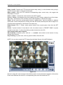
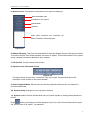
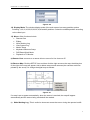
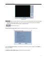
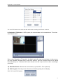
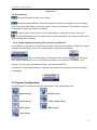
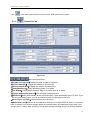
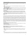
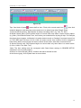
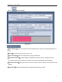
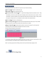
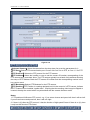
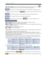
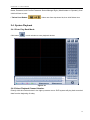
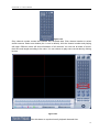
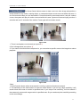
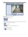
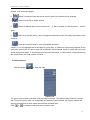
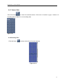
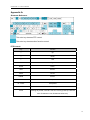
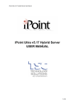
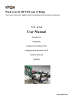
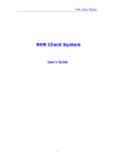
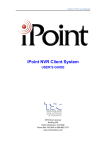
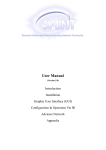
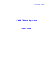
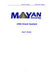
iPoint NVR v5.16 Server User Manual
iPoint NVR Server v5.16
USER MANUAL
1
iPoint NVR v5.16 Server Manual
Table of Contents
iPoint NVR Server v5.16 .................................................................................................................................... 1
USER’S GUIDE..................................................................................................................................................... 1
1. Introduction.......................................................................................................................................................... 3
2. DVR Server ......................................................................................................................................................... 4
2.1 Start Up ...................................................................................................................................................... 4
2.2 Main Interfaces .......................................................................................................................................... 5
2.2.1 Interface Description....................................................................................................................... 5
2.2.2. Instant playback recording files in the current window ............................................................... 13
2.3 System Configuration: ............................................................................................................................. 13
2.3.1. System Set-Up ............................................................................................................................. 14
2.3.2. Camera Setup ............................................................................................................................... 17
2.3.3. Sensor Set-Up .............................................................................................................................. 21
2.3.4. PTZ & Linkage Setup .................................................................................................................. 22
2.3.5. Send Email Setup......................................................................................................................... 25
2.3.6. Digital Matrix Setup .................................................................................................................... 26
2.3.7. System User Set-Up..................................................................................................................... 27
2.4. System Playback ..................................................................................................................................... 29
2.4.1 Enter Play Back Mode: ................................................................................................................. 29
2.4.3 Capture Pictures ............................................................................................................................ 32
2.4.4 Create Clip File ............................................................................................................................. 32
2.4.5 Search Captured Pictures .............................................................................................................. 35
2.4.6 Fast Search .................................................................................................................................... 37
2.4.7 Camera State ................................................................................................................................. 38
2.4.8 Showing files ................................................................................................................................ 39
Appendix A .................................................................................................................................................... 39
2
iPoint NVR v5.16 Server Manual
1. Introduction
Thank you for purchasing the iPoint NVR system. This operation manual was created to help you
quickly and efficiently install the NVR system and its most commonly used features. It is important
to go through this manual, follow each step in order. Read the instructions carefully to ensure
proper programming of the NVR system.
Note: Please set the screen area as 1024x768 pixels before using this system.
System features
•
•
•
•
•
•
•
•
•
•
•
•
•
•
•
•
•
•
•
Hardware support H.264 compression, low HDD cost
Web access through LAN or WAN.
Real time full-motion video-capture & display (Max. 48 channel video input)
Real time high-speed recording: Max. 30 frames/sec per channel
Synchronous audio recording (optional)
Motion detecting (Whole area or max. 12 detection zones per channel)
Normal recording (continuous) and event recording (Motion detection or external sensor)
Electron Map pop-up when alarming
System operating and alarm logging
Alarm-before recording
Remote recording
Alarm message auto-sending
Alarm image auto-sending to email box as attachment
Matrix display and group display
Duplex mode (Recording while playback)
Network support (Remote access via LAN, Ethernet, PSTN, ISDN, ADSL)
P/T/Z/F & speed dome control on keyboard
Search/playback by date/time directory (random-access)
Remote talking between server and client or server and server
Recommended System Requirements
•
•
•
•
Chipset: Intel 845PE, 865PE, 875PE, 915P
Motherboard: Intel: D915PCY, D865PERL Asus: P4P800SE, P5P800 MSI: 865PE Neo2-F,
865PE Neo3-F Gigabit: GA-8PE667, Ultra2 GA-8IPE1000PRO
Video Card: ATI Radeon 9250 128MB ATI Radeon 9550 128MB nVidia GeForce 6200
128MB
nVidia GeForce 6600 128MB
• Processor: Intel Pentium 4 2.4GHz or better
• Memory: 512MB minimum
Recommendations
For optimal performance of your system, it is important to follow these recommendations.
1) Divide your hard disk into two at least two partitions (such as C: and D:).
One partition is for installing Windows OS and system software, the other for storing record files.
2) Please use appropriate motherboard and display card.
3
iPoint NVR v5.16 Server Manual
2. DVR Server
2.1 Start Up
Before you press the NVR power button, please check that all connection interfaces are firmly
connected. Press the NVR system power button, then the application interface will display later
(the time will be decided by how many channels the system has installed, each channel needs
about 4-5 seconds).
on windows
If NVR Autostart has been deleted from start up please double click icon
desktop. The main application interface is as follows:
1
2
9
10
11
12
13
16
8
Figure1-1-1
*Note: If this is the first time the system is run after installation, the operator should setup the
resolution of the compression card.
4
iPoint NVR v5.16 Server Manual
Figure1-1-2
2.2 Main Interfaces
*Show Tips: When the mouse moves close to or stops on a button, the button function text tip will
show immediately.
*Full Screen Mode: Right click mouse button, a menu pops up, select “full screen”, change
display mode to full screen (or press F12 on the keyboard).
*Zoom In/Out Video Image: Double click the left mouse button on a camera window, zoom in/out
video image (or press F11 on the keyboard).
*Recording Status:
a. This icon means the system is recording normally.
b. This icon means the system is recording manually.
c. This icon means the system is recording in motion detect.
2.2.1 Interface Description
1). OSD: Displays the On Screen Display including the current date, time and the camera name.
This information will be watermarked on the recorded files.
2). Version Information: Version of the NVR Software. (v5.16)
3). Color Adjust: Slider adjustments for the video image and recording volume of the selected file.
This also affects the live view of the video images.
5
iPoint NVR v5.16 Server Manual
Increase
Decrease
Figure 1-2-1
①② ③ ④ ⑤
1
2
3
4
5
Allows user to adjust image brightness
Allows user to adjust image contrast
Allows user to adjust image hue
Allows user to adjust image saturation
Allows user to adjust audio
4). PTZ Control:
By pressing and holding these
buttons, the PTZ camera will be
moved up, down, right and left
as well quadrants in between.
Auto Pan: Pressing this button initiates
an automatic tour of all preset positions
by the connected PTZ camera.
Preset zone
Adjust the speed of
speed domes here.
Numeric Panel
Go button (Call out)
Set button (Save preset)
Camera address input field
Figure1-3-1
6
iPoint NVR v5.16 Server Manual
Relay (on/off): Controls the PTZ cameras internal relay (relay1), or the decoders relay (relay1)
Used to turn on a light or control an access gate.
Wiper (on/off): Using the PTZ cameras corresponding wiper control relay, this toggles the
relay/wiper on and off
Zoom +, Zoom- : Controls the zoom function of the PTZ camera.
Focus +, Focus-: Overrides the auto-focus setting of the PTZ camera, adjusts focus of the image.
Iris+, Iris- : Overrides the PTZ cameras auto-iris and brightens or darkens the image.
Setup: Set the speed by moving speed domes to desired place. Input the address in address
space (take 3 as an example here). Finally press the SET button and the pointer will be bright for 3
seconds while programming. Set others in the same way.
Delete Preset: Click “-” button, select preset number from numeric panel, then click the SET
button.
Preset: If preset number is less than16, click its number button in PRESET ZONE. If preset
number is more than 17, call out by clicking number button then click GO.
Auto tracking along with all preset.
Start tracking: In numeric panel, click the “-, + number” (this number is the interval of every
preset), then click GO.
Stop Tracking: In preset zone, click any preset number, then click GO.
NOTE: You can also control the PTZ image from the Main Screen of the NVR Software.
Figure1-2-3
Shown in image #3, each rectangle is the effective action. Arrows denote the direction of the action.
Press and hold down the mouse in a corresponding area, this will control the PTZ.
7
iPoint NVR v5.16 Server Manual
5). Network Panel: The Network Configuration of the system is displayed.
Network adapter type
IP address of the system
Subnet Mask
Gateway
When client computers are connected, the
Client IP address will be displayed
Figure1-2-4
6). Matrix & Display: This panel includes Matrix Groups and Display Groups. Each group includes
16 numeric buttons. Each button denotes one matrix or display. This will be showed in the “system
setup” (detailed information attached in later chapter).
7). DO Control: Controls alarms and sensors.
8). System Active Information Panel:
Figure1-2-5
This panel shows current date, current time, day of the week, free hard disk space and
description of the camera in the current window.
9). Enter Playback Mode: Allows users to enter the playback software suite, and search for
recorded video/audio.
10). System Setup: Dialog box to set up system features
11). System Lock: Prevents unauthorized users to operate system by locking the keyboard and
mouse.
Press
button, the dialog box will be displayed. Input your User ID and Password then press
OK. Default User ID is “admin”, no password.
8
iPoint NVR v5.16 Server Manual
Figure1-2-6
12). Display Mode: The window display mode of the main screen has many partition options
including 1,4,9,12,16,20,25,28,33,36,40 and 49 partitions. Select the suitable partition according
to the video input.
13). Menu: Other functions include
• Remote Chat
• E-Map
• Write Working Log
• View System Log
• Motion Setup
• Keyboard Shortcuts Setup
• DVR Board Work Mode
• Playback to TV Monitor.
a) Remote Chat: connects to a remote client or server for live chat over IP.
b) Electron Map: Click the SETUP icon and then click the right arrow on the map, the dialog box
on the right of the map will appear. Add or delete sensors and cameras (the cameras are those
pointed by the arrow). Or change the digital map as follows:
Figure1-2-7
If e-map is set to appear automatically, when the sensor is touched, the map will appear
automatically and the sensor being touched will be marked.
c)
Write Working Log: This is useful to document events that occur during the operator’s shift.
9
iPoint NVR v5.16 Server Manual
Figure1-2-8
d)
System Log: Allows users to view all recorded activities as well as operator log reports.
System log keeps a record of system events such as shutdown, camera setup changes,
program startup and shutdown, and all Operator or System Administrator’s daily activities
according to time and date. Users can search by date and by system parameters. System
parameter includes operations, system prompts, alarms and other activities.
Figure1-2-9
e) Motion Detection Area & Cover Area Set-Up: Used to set up the built-in motion detection.
By default the entire screen is setup for motion detection as indicated by the green border around
the image. To mask a specific area, first click the DELETE button to get rid of the full screen
detection border. Then left click and hold while stretching a rectangle. A green rectangle will mark
the area of interest. Several areas of detection may be used. Any activity within the green bordered
areas will trigger recording, depending on the reaction method, and alarms may be generated
along with electronic map icons flashing in alert mode. Click the TEST mode icon to test the
sensitivity of motion detection. The sensitivity can be adjusted using the slider bar at the bottom of
the motion detection window.
10
iPoint NVR v5.16 Server Manual
Sensitivity
Figure1-2-10
Add a cover area. If there are some areas you don’t want show, draw those areas with
mouse till they change to black. You can set several coverage areas. Press the Add Mask
button, set cover area, and press again to complete setup.
Delete all cover areas.
f) Keyboard Shortcuts Setup: Disable the fast key functions if you do not want to use.
Figure1-2-11
Click “Lock Sensitive Fast Key”, and choose the fast keys you want to disable. Click “SAVE” to
apply your settings.
g) DVR Board Work Mode Setup: Change DVR board work mode.
11
iPoint NVR v5.16 Server Manual
The new DVR board work mode will take effect after restarting DVR Server software.
h) Playback to TV Monitor: In DVR system, the recorded data can be transmitted to TV monitor
via the Matrix Card.
When using “Playback to TV monitor”, the Matrix card will output recorded data. In this process,
you can playback recorded files by date and camera, and the recorded files will be played
automatically by turn. Otherwise the matrix decoder card will output real time video according to
your setup.
14). Minimize Button: Minimize the main window (or press WIN + Z on keyboard).
15). Exit Program: Click this power off button and following dialog box will display.
Click “OK” to quit DVR system.
12
iPoint NVR v5.16 Server Manual
Figure1-2-12
16). Function Key:
Cameras Sequence Partition auto-switch.
Emergency Record Button: This button triggers recording by all cameras for 30 seconds,
Even if they have been setup to record by motion, sensor or time period. This function is useful in
an emergency where quick action is required.
Image Capture: Allows users to save a still images of a selected camera in live view.
Manual Record Button (on/off): Allows users to record manually by any camera. (Note: must
stop manually after recording).
2.2.2. Instant Playback Recording Files in the Current Window
Press TAB key on keyboard, or press Page UP (select next camera window) or Page Down (select
last camera window) key, select one camera window, right click mouse button.
Select “Instant playback”, and another menu will popup
, choose the
time, system will playback in the current window according to your selection. For example, if you
choose 1 min the system will playback the last 1 minute of recorded files.
If you want to stop the instant playback, right click mouse button in the playback window, and select
End Playback.
2.3 System Configuration:
The DVR System Configuration and Set-Up includes 7 sub configuration icons
System set-up
Camera set-up
Sensor set-up
PTZ & linkage set-up
Email set-up
Matrix set-up
User set-up
13
iPoint NVR v5.16 Server Manual
Click
2.3.1.
in the main system screen to enter into the DVR system set-up mode:
System Set-Up
Figure1-3-1
Set system parameter
【Number of Channels】Display the total number of channels.
【Sensor Input (DI)】 Display the number of sensors (DI).
【Sensor Output (DO)】Display the number of alarms (DO).
【Audio Monitoring】Select monitoring audio or no audio.
【Use E-Map】Select display Electron Map or not when there is an alarm.
【Camera Sequencing Interval】Set auto-split changing speed.
【DI/DO Port】Select sensor/alarm driver connection port, it must be different from PTZ Port. If you
do not use alarming input, you can close this function to save system resource.
【Save Log for (x) Days】Log save days(max 100 days).
【When Disk is Full】Select record mode when there is not enough HDD free space. If “Overwrite
data” is selected, DVR system will auto-delete the recorded data of the earliest day when there is not
enough space. If select “Stop recording” DVR system will stop recording and give a warning message.
14
iPoint NVR v5.16 Server Manual
【Main Recording Disk】Select the first disk partition from which the DVR saves data. The previous
disk of this one will not be used to record or will not be checked by the system.
【System Keystroke】When it is in use, some system keys will be disabled such as (Ctrl+Alt+Del).
【DI/DO Device】Select alarm driver type.
【Alarm Beep】Disable or enable beep alarm from drop-down list. When there is an alarm, system will
make beep noise if “enable” is selected.
【Date Format】Select date mode. It decides the date mode in the information panel
on the main screen in the date panel.
(
) of the playback window.
【Time Format】select time mode.
【Remote Connection】Select using the network or not.
【Remote Port】 Select remote connection port.
【Remote Buffer Priority】There are three items “smooth” demands the system to Buffer in “real
time” to have enough bandwidth. Otherwise, the data will be jumpy when they are sent by the net.
【Automatic Alarm Notification Client IP】Assign a network client to receive alarm message
when there is an alarm. The alarm channel image will auto display in the client software.
【Alarm Send Port】This is the alarm message connection port.
【Web Server Port】This is IE client connection port.
【Use DNS】 Select DNS or not for supporting dynamic IP.
【Local Host Name】Input the name for DNS Server identification.
【DNS Server IP】DNS server host IP.
【DNS Connection Port】DNS server host port is provided to connect DNS software.
【Interval Connection Time】 Interval time connects DNS automatically.
【Permit Max Connect Video Num】The maximum clients permitted to connect to the DVR server.
The number can be setup according to the network bandwidth. The maximum is 256.
*Note: Alarm auto connection to IP is used to input alarms automatically. When a sensor, normal
or motion record is set to input and there is IP address, the system will check if the client has
connected with this system. If there is no connection, the system will try to connect to it through
Port 5300 (preset). When it cannot connect, the system will keep trying till the connection is OK.
*Note: DNS server work mode.
15
iPoint NVR v5.16 Server Manual
Figure 3-2
1. If your DVR uses a dynamic IP, you should configure your DVR system as follow :
Figure1-3-3
2. The DNS server will get your DVR’s domain name and the current IP.
Figure1-3-4
3.
Clients will get the DVR’s current IP through DNS the server according to the DVR’s domain.
4.
Clients will visit DVR through the IP its get from DNS server.
For stability purposes, the system can be set to restart automatically.
【Exit to Windows】 Users can exit program and back out to the windows desktop.
【Exit and Shutdown】Users can exit program and shut down the computer.
【Auto Shut Down】Schedule shutdown of the computer.
【Auto Reboot Date(Mon-Sun)】Select auto restart days.
【Reboot at】Set auto-restart time.
16
iPoint NVR v5.16 Server Manual
2.3.2.
Camera Setup
Figure1-3-5
Individual setup
【Selected Camera】 Set the parameters for a camera by selecting the camera from the drop-down
list.
【Camera Description】Input the description for easy identification.
【Camera Type】Select camera type from drop-down list. Users can choose from PAL or NTSC.
【Camera】Enable or disable selected camera. Video loss detection will sound if a camera is not
physically connected while enabled.
【Bit Rate】Set record mode. Variable Bit Rate (VBR) or Constant Bit Rate (CBR) Recording.
VBR allows each frame to be recorded and the bit rate to go up or down, depending on the image
complexity, activity and color. CBR allows each frame to be recorded at fixed rate, irrespective of
scene activity. In many cases, this limits detail (resolution). The benefit of CBR is its ability to
accurately estimate the total video storage time.
【Image Size】Users can select from CIF, Half D1 and Full D1 Image Sizes. If Full D1 is used the
recording will be around 12-15 FPS.
17
iPoint NVR v5.16 Server Manual
【Image Quality】Sets the quality of the image to be recorded from Poorest, Poor, Medium, Very
Good and Best.
Click this button and users can choose advanced settings for video quality, such as IBP,
FPS and Maximum Bit Rate.
【Frame Rate(fps)】Sets the recording rate for selected camera. For Frames Per Second (fps),
the rate should be from 1 to 30 fps.
【OSD Contrast】
【OSD Pos】 Sets On Screen Display controls brightness and position. Selecting
“auto” in the OSD Contrast’s drop-down list will make the OSD best suit the background color
automatically.
【Record Days】 This section allows users to determine how long the recorded data of each
camera should be kept by the system. The maximum duration for on-line storage is 120 days.
Users can select number of days, or can select “auto” mode. If “auto” is selected the system will
auto-delete the recorded data of the earliest days, when there is not enough space.
【Swap File】Set recorded video file size saved on the HDD. For easy backup, don’t set the file size
too large.
*NOTE: If there is not enough space of HDD, the system will delete the recorded data according to
the length of saving time of each camera. E.g.: there are four cameras, the 1st camera save 2 days,
the 2nd camera save 5 days, the 3rd camera save 10 days, and the 4th camera is set at “auto” mode.
If there is enough space, the 4th camera’s record data will be saved in HDD, while there is not
enough space the system will delete data automatically. If the 4th camera’s record data has been
saved more than 10 days, system will delete the 4th camera’s data, if the 4th camera’s recorded
data has been saved less than 10 days, but the 3rd camera’s data is more than 10 days, system will
delete the 3rd camera’s data. So, even if you set the 3rd camera’s recorded data saving 10 days, the
data which is saved less than 10 days is deleted. System will delete the record data from the
earliest date.
【Copy Set Up to】Set all cameras with the same setup.
【Masking Bitmap File】Watermark function ,the logo picture must be edited at 128 * 128 pixels
and saved as .bmp file.
【Remote Frame Rate(fps)】Sets the frame rate of the client.
【Remote Image Size】Select image resolution to be transmitted to the client side.
【Remote Quality】Set the quality of image of the client side to be recorded from Poorest, Poor,
Medium, Very Good and Best.
Click this button, users can make advanced setup for video quality for the client end. You
can setup IBP frame and maximum bit rate, and adjust Max bit rate according to the network
bandwidth.
*Notes:
1. If less than 64 cameras are in use, many of them can not provide pictures sometimes and an
alarm will appear (beep to tell you some video information is missing). Set the camera with no
18
iPoint NVR v5.16 Server Manual
picture as disabled and the alarm will disappear. When you want to use them later, set as enabled
again.
2. The unit of the swap file should be MB. 2-50 is the range.
3. Set the position and contrast of the date shown on the screen. Sometimes the date cannot be
clearly seen for its color is similar with the background. You can change its position or color when
this happen.
4. Image size is the format used when recording. And Remote image size is the format used when
these images are transmitted to client sides.
5. Remote Frame Rate, Remote image size and Remote Quality are the parameters of the client
side. When the server’s resolution is set as “D1 Auto F”, these three items are no effected. The
client’s parameters will be same as the server. When the server’s resolution is set as others
(except “D1 Auto F”), if Remote image size is set as “with record”, Remote Frame Fate(fps) and
Remote Quality are not effected, the client’s parameters will be same as server’s.
5. Variable Digital Rate Table
Image quality
Poorest
medium
best
recording environment
occupied disk space (/com/hour)
low action indoor
about 45mb
high action road
about 95mb
low action indoor
about 70mb
high action road
about 180mb
low action indoor
about 160mb
high action road
about 320mb
*Note: Invariable digital rate can not improve image quality but it is helpful for counting disk space.
Variable digital rate recording is recommended.
Cameras can be grouped to work according to time lists.
Note: If you setup groups with conflicting camera, then only the last setup is going to work.
【Selected Group】Select group number.
【Selected Cameras】 Select the camera that have the same work mode with group.
【Pre-Event Record】 Select the start time of record when there is an alarm. When DVR system is
in Motion Detect mode or Sensor Detect mode, it can record video before the alarm is trigged.
【Post Record Time】Select the end time of record when there is an alarm. When the system is in
Motion Detect mode or Sensor Detect mode, it can record video after the alarm end.
【Record Audio】Selects Yes or not.
Schedule Setup (Example for the following figure)
19
iPoint NVR v5.16 Server Manual
Figure1-3-6
Tips: One block of pane
means half an hour. Firstly click record mode icon
, then click
schedule diagram, hold down the mouse and move it to select large area (Drag & Drop).
1. Normal Record (Green): DVR System is always recording video. (e.g. Sun. Fri. Sat.)
2. Motion Detect (Blue): DVR System begins to record video only when it detect moving object.
(e.g. Mon.) Click "Motion Detect" icon, then select your schedule time by drag & drop. For example,
the above picture means: on Monday it is motion detect record, on Sunday it is normal record, but
on TUE, WED and THU from 3:30 to 11:00 it is sensor record, from 14:00 to 22:30 it changes to
both motion detect record mode and sensor detect record mode, other time is normal record.
3. Sensor Record (red): DVR System begins to record video only when there is a sensor alarm.
(3:30 to 11:00 in Tue. Wed. Thu.)
*Note: The time setting must be correspond with Check Alarm settings in SENEOR SETUP,
otherwise it can not work properly.
4. Motion or Sensor Record (yellow): Combine with above 2 and 3 function.
5. Not Record (gray): DVR System does not record video.
20
iPoint NVR v5.16 Server Manual
2.3.3.
Sensor Set-Up
Figure1-3-7
【Select Sensor】Select the camera from the drop-down list in order to set the parameters for a
sensor.
【Sensor】 Select this sensor port to use or not.
【Sensor Position】Enter the description for easy identification.
【Activate PTZ Preset】 Select linkage of Speed Dome preset number . Speed Dome will
auto-move to this preset number when there is an alarm. (Need Speed Dome installed).
【Play Alarm Sound】 Select a sound of .wav for a sensor, if there is alarm, the sound file will be
played.
【Link to PTZ】Select which Speed Dome respond with this sensor alarm.
21
iPoint NVR v5.16 Server Manual
Sensor group set up is very similar to the group set up of camera recording.
【Sensor Type】Select N/C or N/O alarm type.
【Alarm Write log】Select write alarm log or not.
【Alarm Action After It Times-Out】Select system alarm linkage mode after an alarm time-out. “Stop
Immediately” means the system stop alarm immediately after the alarm driver stops an alarm. “Follow
Input State ” means the system don’t stop alarm after the alarm driver stops an alarm. “Delay” means
the system will stop alarm at your setting time after the alarm driver stops an alarm.
【Sensor input】Add sensor to selected group.
【Start recording cameras】Select which cameras respond with this sensor group. They will start
recording and auto connect remote network client when there is an alarm.
【Trigger Output Relays】Add alarm devices (alarm out port) to this group. E.g. siren, light. All
connecting devices will send alarm message when there is an alarm.
Schedule Setup (Example for below figure)
Figure1-3-8
1. Check Alarm (Red): DVR System responds with sensor in this time. (00:30 to 12:00 from Sun. to Fri.)
2. Not Check (gray): DVR System doesn’t respond with sensor in this time.
Note: If you setup groups with conflicting camera, then only the last setup is going to work.
2.3.4.
PTZ & Linkage Setup
22
iPoint NVR v5.16 Server Manual
Figure1-3-9
【Selected Camera】Select the camera from the drop-down list to set the parameters for it.
【PTZ Port】Selects PTZ communication port. Choose “No Com” for no PTZ, or Com 1, 2 for PTZ.
【PTZ Protocol】Selects the PTZ protocol for the PTZ camera.
【PTZ Address】Allows the installer or user to set the camera ID number corresponding of the
PTZ camera being controlled. Note: The PTZ camera typically has a bank of dip switches allowing
the setup of PTZ address. Both the PTZ camera ID number and the corresponding number in this
box need to match.
【PTZ Baudrate】Selects PTZ Baudrate for the PTZ camera.
【PTZ Position】PTZ Position is a setting designed to aid in the control of a PTZ camera, it allows
the PTZ camera to be installed “upside down”, requiring that the resulting video image be flipped or
inverted, thereby the control which is synchronized with the camera direction works.
Notes:
1. PTZ position will influence PTZ control. e.g.: if you set as obverse and press left, then it will turn left.
If you set as inverse and press left, then it will turn right.
2. If there is (H) after the PTZ protocol, it has the function of high speed Preset. If there is no (H), then
it only has the function PTZ control.
23
iPoint NVR v5.16 Server Manual
【DO Port】【DO Port Name】If an alarm input is in use and there is alarm associated with a
camera, the alarm will be sent to the client automatically, same with sensors. But the client will only
automatically connect to the cameras when an alarm is detected.
【Send Alarm to Client】Selects whether alarm are sent to a network client or not.
【Motion Detected In Camera】Selects camera from dropdown list.
【Play Alarm Sound】Selects a “.wav” sound file for a camera alarm. If there is an alarm, the
sound file will be played.
【Trigger DO Output】Selects which DO port responds with an alarm on a camera. All connected
devices will send an alarm message when there is Motion Detect.
Schedule Setup
Figure1-3-10
1. Check Alarm is (Red): DVR System responds with Motion Detected and sends an alarm
message only in the time selected. (Every day 00:00 to13:00)
2. Not Check is (Gray): DVR System doesn’t respond with Motion Detected in the time not selected.
Note:
1. The time settings must correspond with Motion Detection time under CAMERA SETUP,
otherwise it will work improperly.
2. Check Alarm Setting does not affect Motion Detection Record. It is only an alarm setting.
24
iPoint NVR v5.16 Server Manual
2.3.5.
Send Email Setup
Figure1-3-11
【SMPT Server】SMTP server address. E.g.: mail.ipontllc.com.
【SMPT Port】SMTP listen TCP’s port for connection requests.
【Authentication Type】 Login mailbox, operator will select SMTP authentication type, or select
“simple login”.
【Login User ID】Mailbox ID.
【Login Pass】 Mailbox password.
【Send To】Address of receiver.
【Sender Email】Operator’s email address.
【Email Screenshot as Attachment】When there is alarm, the system will grab picture, operator can
select whether send the picture as attachment .
【Send Notification from Cameras (Screenshot From Alarm Camera)】Operator can select which
cameras alarm send email.
25
iPoint NVR v5.16 Server Manual
【Send Notification from Sensors (Screenshot From Linked Camera)】Operator can select which
sensors alarm send email.
*NOTE: If send the grab picture as the attachment, you should set the alarm of the camera or sensor,
to “alarm send to network” enabled.
2.3.6.
Digital Matrix Setup
Figure1-3-12
【Matrix Group】System operator can organize into groups to matrix video out, each group has
different display mode. There are 16 groups in common.
【Video Out Port】Matrix video out channel.
【Video Out Standard】Matrix video out standard, select PAL and NTSC.
【Video Split Mode】Video out display mode, there are 1 split
, 2 split
, 4 split
,9
, 13 split
and 16 split
.
split
【Video Window】【Display Video Camera in window】After selecting video split mode, select a
camera number an window where you would like that camera to display. Multiple cameras can be
selected for one window, with a time interval for the camera to cycle.
【Video Switch Interval(sec)】Time Interval that each window shows cameras circularly when there
have more than one camera in one window.
26
iPoint NVR v5.16 Server Manual
【Display Group】 System operator can organize groups to display video out, each group has
different display setup number from 1 to 16.
【Video Split Mode】Video out display mode, the split mode is the same as main window’s
display split mode. There are 1, 4, 9, 12, 16, 20, 25, 28, 33, 36, 40 and 49 partition options.
【Video Window】
【Display Camera in the window】 After selecting the video split mode, select
a corresponding display video window, select one camera show in a window.
*Note: One camera is only showed in one window once, but each camera can display any window
discretionarily. E.g.: The 1st camera has been displayed in window 1, and the 2nd camera has been
displayed in window 2. If you change camera 1 to be displayed in window 2, camera 2 will
automatically display window 1.
2.3.7.
System User Set-Up
Figure1-3-13
Creates user accounts based on administrator or operator privileges. This DVR system supports
up to 256 users.
27
iPoint NVR v5.16 Server Manual
【Use Password】 Click it to enable User Manage mode and activate the lock button
main window. Only authorized user can log into System at User Manage Mode.
in
Add a new user .Press this button, and input user information, including user name,
password, and user level. Then Press
button, the new user will be added in user list.
Select user from user list, and modify his information and authority, then click
button, system will save user’s information and authority.
Select a user from user list, and click
button, system will delete this user.
【User Name】Input new User ID in this box when adding a new user to system.
【Password】Set new user or selected user’s password.
【Rights Level】Select user type. Only Administrator can enter User Manage Window and have
the access to user management.
【Full Name】Input your description of this user.
【Confirm】 Confirm password again.
a. Watch Camera –every user is granted access to view live images by default. To deny access,
click a camera button and the blue button changes to gray.
b. Search Camera – Rights to view recorded video by each camera. By default every user is
granted access to record video by all cameras. Granted rights are outlined in blue, denied access
displays in gray, the same as Watch Camera.
c. Operation Right- Select operational tasks, granting or denying rights. Operational tasks are
normally reserved for administrative, privileged accounts. Operators are rarely granted rights to
adjust camera color, exit program, explore files or operate PTZ controls.
Figure1-3-14
d. Setup User Right- Select setup rights to grant or deny user privileges.
Figure1-3-15
e. Add New User Button-
Maximum quantity is 16 users in one system. Click
to add new user. The cursor will show the “user name” frame. Input System Name, Note
28
iPoint NVR v5.16 Server Manual
Name, Password, and Confirm Password. Select Manage Right, (Administrator or Operator), then
click Add User to save.
f. Delete User Button-
Select user from drop-down list, then click Delete User.
2.4. System Playback
2.4.1 Enter Play Back Mode:
Click button
in main window to enter playback window.
Figure1-4-1
2.4.2 Select Playback Channel Number:
Directly click the number button in the right-up screen corner. DVR system will play back recorded
data from the beginning of today.
29
iPoint NVR v5.16 Server Manual
Figure1-4-2
Gray channel number means that channel has recorded data. Click channel number to select
search camera. Select one window (the 1st one is default), click the channel number and playing
will begin. Different colors will show information of all cameras. You can see all kinds of record,
their time and length according to the color. You can choose to play some record data by clicking
its time.
Figure1-4-3
Click this button to synchronize all playback channels time.
30
iPoint NVR v5.16 Server Manual
The Smart Search allows users to draw a zone on video image and perform a
search based on any motion, missing object, or unattended object events occurred within that zone. It
can find recorded video you are interested in. Press this button to start smart search, and pull a select
a area, the system will play all motion occurred within this area. System will start and play previous 3
seconds and next 3 seconds of the motion. Press again will end smart search.
①
②
Figure1-4-4
1. There is a telephone on the desk (see picture 1).
2. But it disappeared (see picture 2).
3. If you want to know where the telephone is, you can select a specific area on the image then select
playback.
Figure1-4-5
*Note:
1. Press Synchro button when smart search is running, system will end smart search.
2. The sensitivity of the smart search is same as motion detect. If you set up a high sensitivity, it will
search when there was no motion in specified area. If you setup a low sensitivity, it will not search if
there was only some small range motion in specified area. So you need setup the sensitivity according
to the surroundings.
31
iPoint NVR v5.16 Server Manual
Last frame, Start, Pause, Stop and Next frame
First frame of that day, Last Minute, Next Minute, and Last Frame of that day.
Image Zoom Out. Press this button, single click the left mouse button on an image. Quarter
of the image will be enlarged. Thereafter, single click right mouse button on the image, it will
resume to the normal.
Adjust Voice. Click the button to clear the voice.
Adjust Playing Speed. Click the button to resume normal playing speed.
2.4.3 Capture Pictures
Click capture button
to capture a display picture. When one is captured, dialog interference
will appear to ask you to input a file name. After you press confirmation, you will be asked to input the
path.
*Note: the size of the image is that of the playing window.
2.4.4 Create Clip File
Click button
,there are three options
to select.
A. Create File Clip:
Figure1-4-9
32
iPoint NVR v5.16 Server Manual
a.
Select one from file list and double click it ,this file will be played.
Information of the playing file. Including beginning time, ending time, file size,
b.
resolution, frame rate etc.
Play control button
c.
d.【Select Camera】Change a channel conveniently.
e.【Save path】Select clip file’s save path.
f.
Set the beginning position and ending position of the file, the file attribute on the left will
show the size of the file.
h.
i.
Ensure the beginning and end of the file, click it to save the file.
Voice control, press it to clear voice.
B. Backup by Time:
33
iPoint NVR v5.16 Server Manual
Figure1-4-10
【Save Path】Select “save path” for the backup file.
【Backup Camera】Select the backup camera.
【Select begin time】
【Select end time】Select the backup files’ beginning time and ending time.
【Unite File】Enable or disable unite file . If select disable, the record file will not united. If select enable,
all record files will be united. Users can set the Max. value of the united file.
【Backup File Max Value】Max. value of the united file. If the file’s value big than max value, it will be
split. Users can check the file’s value by using button
, it’s value will be showed in【Backup
Date Size】
C. View Backup File
34
iPoint NVR v5.16 Server Manual
Figure1-4-11
a.【Save Path】Select path of the backup file.
b【Select Channel】 Select channel.
Select one from File List and double click it ,this file will be played. The united file is
c.
named by “date + begin time” and “date + end time”.
d.
Start writing CD
e.
Copy the player to the catalog of the backup file.
2.4.5 Search Captured Pictures
Click
to enter the search window:
35
iPoint NVR v5.16 Server Manual
Figure1-4-12
a.
Directory list.
b.
File list.
c.
Name and path of current picture. If
you want to save the reworked picture in another file, you can change its name and path here, with
bmp and jpg as suffix. Then click the button
d.
e.
f.
g.
.
Save the reworked picture.
Function buttons of picture disposal.
When the result of disposal is not good click it to the default.
Print picture. When the image is wider than 400 pixels, it will be printed smaller. If it is
36
iPoint NVR v5.16 Server Manual
smaller, it will be printed bigger.
When it’s selected, with the mouse moving, part of the picture will be enlarged.
h.
i.
Delete current file or delete all files.
J.
Button of Window split, in server there are 1,4,9and 16 splits. In client there are 1, 4 and 9
splits.
k.
Open all: press this button, open all playback windows in turns according to the order of the
cameras.
l.
Close all: press this button, close all playback windows.
*Note:1.It is not suggested that multi-channel (more than 10 channels) record and playback at the
same time unless your PC has a large HD and RAM 2. Multi-channel search in client and server are
similar except their paths. In client there are local and LAN search. In LAN search, it searches among
the record data in the local network of server.
2.4.6 Fast Search
Click this button
to show the date:
Figure1-4-6
The green number means that there is Record Data on that day. The yellow number means the current
day. Only those green ones can be selected and when they are selected, the camera window will
appear automatically to show which cameras has recorded data.
Click
or
to change month and year of search data.
37
iPoint NVR v5.16 Server Manual
2.4.7 Camera State
Click this button
to show the cameras status. If the color of number is gray, it means it is
recording data. If white, it is not recording data.
Figure1-4-7
2.4.8 Showing Files
Click this button
to show all the files of current cameras.
Figure1-4-8
38
iPoint NVR v5.16 Server Manual
Appendix A:
Shortcuts Reference:
This color key denotes PTZ control.
This color key denotes other function control.
PTZ Control:
Key
Function
↑
Up
↓
Down
←
Left
→
Right
Home
Zoom-
End
Zoom+
Insert
Focus-
Delete
Focus+
S
Save preset
G、Enter
Call preset
C、—、 Num0-9
Presets Control Operation
F3-F8
Tracking all presets, interval is 3-8 Sec of every preset.(F3 denotes
3sec.F4 denotes 4 sec,F8 denotes 8 Sec etc.)
39
iPoint NVR v5.16 Server Manual
Other Control:
Key
Function
F1
System Help
Tab
Switch the camera channel
Page Down
Switch to the next screen
Page UP
Switch to the previous screen
F9
All cameras begin recording in 30 Sec while emergency
F11
Zoom in/out the single camera view
F12
Switch to Full screen mode
WIN+ Z
Minimize the Main System window
40