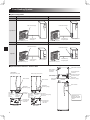
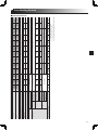
1
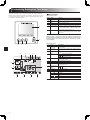
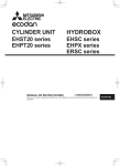
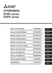
Cylinder Unit
EHST20 series
EHPT20 series
OPERATION MANUAL
Hydrobox
EHSC series
EHPX series
FOR USER
For safe and correct use, please read this operation manual thoroughly before operating the cylinder unit and
the hydrobox.
Bedienungsanleitung
FÜR NUTZER
Lesen Sie sich zur sicheren und korrekten Verwendung diese Bedienungsanleitung bitte sorgfältig durch, bevor Sie den Speicher und die Hydraulikeinheit.
Mode d'emploi
POUR LES UTILISATEURS
Pour garantir une utilisation sûre et appropriée, lisez attentivement le présent mode d'emploi avant d'utiliser le
module hydraulique combiné et le module hydraulique.
Handleiding
VOOR DE GEBRUIKER
Voor een veilig en juist gebruik moet u deze handleiding goed doorlezen alvorens de cilinder-unit en hydrobox
in gebruik te nemen.
MANUAL DE INSTRUCCIONES
PARA EL USUARIO
Para un uso correcto y seguro de la unidad cilindro y del Hydrobox, lea este manual de instrucciones antes de
su utilización.
Manuale di funzionamento
PER L’UTENTE
Manual de Funcionamento
PARA O UTILIZADOR
Per un uso corretto e sicuro del dispositivo, leggere attentamente il presente manuale di funzionamento prima
di utilizzare dell'unità con bollitore e dell'hydrobox.
Para uma utilização segura e correcta, é favor ler cuidadosamente este manual de funcionamento antes de
trabalhar com o no cilindro e nos hídricos.
Brugsvejledning
TIL BRUGER
Användarmanual
FÖR ANVÄNDAREN
Læs venligst denne brugsvejledning grundigt inden betjening af den i cylinderenheden og hydroboksen.
För säker och korrekt användning, var god läs denna användarmanual noggrant innan du använder i tanken
och hydroboxen.
Bruksanvisning
FOR BRUKEREN
Les denne bruksanvisningen nøye før du bruker i sylinderenheten og vanntanken i bruk, for å sikre trygg og
riktig bruk.
Käyttöopas
KÄYTTÄJÄLLE
Turvallisen ja asianmukaisen käytön varmistamiseksi lue tämä käyttöopas huolellisesti ennen varaajayksikkö
ja hydrobox käyttöä.
English
Deutsch
Français
Nederlands
Español
Italiano
Português
Dansk
Svenska
Norsk
Suomi
Contents
1. Safety Precautions............................................ 2
Disposal of the Unit.......................................................... 2
2. Introduction........................................................ 3
Overview of the System................................................... 3
How the Heat Pump Works.............................................. 3
Economical Best Practice................................................ 4
Overview of Controls....................................................... 4
3. Your Heating System......................................... 5
System Configuration...................................................... 5
Important Parts of the Units - Points to Note................... 5
Product Specification....................................................... 6
4. Customising Settings for Your Home.............. 7
Main Controller................................................................ 7
General Operation........................................................... 8
Changing Initial Settings.................................................. 8
Schedule.......................................................................... 9
Holiday Mode................................................................. 10
Heating Mode................................................................ 10
Domestic Hot Water (DHW) / Legionella Prevention......11
Service Menu................................................................. 12
5. Service and Maintenance............................... 13
Troubleshooting............................................................. 13
Maintenance.................................................................. 13
Abbreviations and glossary
Abbreviations/Word
Description
Ambient temperature
The outdoor temperature
Freeze stat. function
Heating to prevent water pipes freezing
ASHP/HP
Air source heat pump
COP
Coefficient of performance the efficiency of the heat pump
Cylinder unit
Indoor unvented DHW tank and component plumbing parts
Hydrobox
Indoor unit housing the component plumbing parts and a plate heat exchanger
DeltaT
Difference in temperature between two variables
DHW mode
Domestic hot water heating mode for showers, sinks, etc
Flow rate
Speed at which water circulates around the primary circuit
Flow temperature
Temperature at which water is delivered to the primary circuit
FTC3
Flow temperature controller, the circuit board in charge of controlling the system
Compensation curve mode
Space heating incorporating outdoor temperature compensation
Heating mode
Space heating through radiators or UFH
Legionella
Bacteria potentially found in plumbing, showers and water tanks that may cause Legionnaires disease
LP mode
Legionella prevention mode – a function on systems with tanks to prevent the growth of legionella bacterium
Packaged model
Plate heat exchanger in the outdoor heat pump unit
Refrigerant
A compound used within the heat cycle that goes through a phase change from gas to liquid
Split model
Plate heat exchanger in the indoor unit
TRV
Thermostatic radiator valve – a valve on the entrance or exit of the radiator panel controlling the heat output
UFH
Under floor heating – a system of water carrying pipes under the floor, that warms the floor surface
1 Safety Precautions
► Before operating this unit it is important to read the safety precautions.
► The following safety points are provided to prevent injury to yourself and damage to the unit please adhere to them.
Used in this manual
WARNING:
Precautions listed under this title should be observed to prevent
injury or death to the user.
CAUTION:
Precautions listed under this title should be observed to prevent
damage to the unit.
• Follow the instructions provided in this manual and local regulations when using this unit.
WARNING
•
•
•
•
•
•
•
•
•
•
•
•
•
•
•
•
•
The unit should NOT be installed or serviced by the user. If installed incorrectly water leakage, electric shock and fire may result.
NEVER block discharges from emergency valves.
Do not operate the unit without emergency valves and thermostatic cut outs being operational. If in doubt contact your installer.
Do not stand on or lean on unit.
Do not place objects on top or below the unit and observe service space requirements when placing objects next to the unit.
Do not touch the unit or controller with wet hands as electric shock may result.
Do not remove the panels of the unit or try to force objects inside the unit’s casing.
Do not touch protruding pipework as it may be very hot and cause burns to the body.
Should the unit start vibrating or making abnormal noises stop operation, isolate from the power supply and contact the installer.
Should the unit start to produce any burning smells stop operation, isolate from the power supply and contact the installer.
Should water be visibly being discharged through the tundish stop operation, isolate from the power supply and contact the installer.
The Mitsubishi Electric cylinder and hydroboxes are NOT intended for use by children or infirm persons without supervision.
Care should be taken to prevent children and pets having easy access to the units.
In the case of a refrigeration leak, stop the operation of the unit, thoroughly ventilate the room and contact the installer.
If power supply cable is damaged, it must be replaced by the manufacturer, its service agent or similarly qualified persons in order to avoid a hazard.
Do not place containers with liquids in on top of the unit. If they leak or spill the unit may be damaged and fire could occur.
When installing or relocating, or servicing the cylinder unit and the hydrobox, use only the specified refrigerant (R410A) to charge the refrigerant lines.
Do not mix it with any other refrigerant and do not allow air to remain in the lines. If air is mixed with the refrigerant, then it can be the cause of abnormal
high pressure in the refrigerant line, and may result in an explosion and other hazards.
The use of any refrigerant other than that specified for the system will cause mechanical failure or system malfunction or unit breakdown. In the worst
case, this could lead to a serious impediment to securing product safety.
CAUTION
• Do not use sharp objects to press the buttons of the main controller as this will cause damage to the buttons.
• If power to unit is to be turned off for a long time, the water should be drained.
• Do not place a container etc. filled with water on the top panel.
Disposal of the Unit
<Figure 1.1>
This symbol mark is for EU countries only.
This symbol mark is according to the directive 2002/96/EC
Article 10 Information for users and Annex IV, and/or to the
directive 2006/66/EC Article 20 Information for end-users and
Annex II.
Your Mitsubishi Electric heating system products have been manufactured with high quality materials and components which can
be recycled and/or reused. The symbol in Figure 1.1 means that
electrical and electronic equipment, batteries and accumulators
at the end of their life, should be disposed of separately from your
household waste.
If a chemical symbol is printed beneath the symbol (Figure 1.1),
this chemical symbol means that the battery or accumulator contains a heavy metal at a certain concentration. This is indicated as
follows;
Hg: mercury (0.0005%), Cd: (cadmium (0.002%), Pb: lead (0.004%)
In the European Union there are separate collection systems for used electrical
and electronic products, batteries and accumulators.
Please dispose of this equipment, batteries and accumulators correctly at your local community waste collection/recycling centre.
Contact your local Mitsubishi Electric dealer for country-specific details on
disposal.
Please, help us to conserve the environment we live in.
2 Introduction
The purpose of this user manual is to inform users how their air source heat
pump heating system works, how to run the system at its most efficient and how
to change settings on the main controller.
This appliance is not intended for use by persons (including children) with
reduced physical, sensory or mental capabilities, or lack of experience and
knowledge, unless they have been given supervision or instruction concerning the use of the appliance by a person responsible for their safety.
Children should be supervised to ensure they do not play with the appliance.
This user manual should be kept with the unit or in an accessible place for
future reference.
Overview of the System
The Mitsubishi Electric Air to Water (ATW) heat pump system consists of the following components; outdoor heat pump unit and indoor cylinder unit or hydrobox
incorporating main controller.
Schematic of package cylinder system
How the Heat Pump Works
Space heating and DHW
Heat pumps take electric energy and low grade heat energy from the outdoor air
to heat refrigerant which in turn heats water for domestic use and space heating.
The efficiency of a heat pump is known as the Coefficient of Performance or COP
this is the ratio of heat delivered to power consumed.
The operation of a heat pump is similar to a refrigerator in reverse. This process
is known as the vapour-compression cycle and the following is a more detailed
explanation.
1. Compressor
The first phase begins with the refrigerant being cold and low pressure.
1. The refrigerant within the circuit is compressed as it passes through the compressor. It becomes a hot highly pressurised gas. The temperature also rises
typically to 60°C.
2 kW
1 kW
3. Expansion valve
4. Evaporator
(Outdoor unit air heat exchanger)
Low temperature renewable heat
energy taken from the environment
Electrical power input
2. Condenser
(Plate heat exchanger)
Useful energy output
3 kW
2. The hot refrigerant gas is then condensed as it passes across one side of a
plate heat exchanger. Heat from the refrigerant gas is transferred to the cooler
side (water side) of the heat exchanger. As the temperature of the refrigerant
decreases its state changes from a gas to a liquid.
3. Now as a cold liquid it still has a high pressure. To reduce the pressure the liquid passes through an expansion valve. The pressure drops but the refrigerant
remains a cold liquid.
4. The final stage of the cycle is when the refrigerant passes into the evaporator
and evaporates. It is at this point when some of the free heat energy in the outside air is absorbed by the refrigerant.
It is only the refrigerant that passes through this cycle; the water is heated as it
travels through the plate heat exchanger. The heat energy from the refrigerant
passes through the plate heat exchanger to the cooler water which increases in
temperature. This heated water enters the primary circuit and is circulated and
used to serve the space heating system and indirectly heat the contents of the
DHW cylinder (if present).
2 Introduction
Economical Best Practice
Air source heat pumps can provide both hot water (providing a suitable cylinder is
used) and space heating all year. The system is different to a conventional fossil
fuel heating and hot water system. The efficiency of a heat pump is shown by its
coefficient of performance as explained in the introduction. The following points
should be noted to achieve the most efficient and economical operation of your
heating system.
Important points about heat pump systems
• Domestic hot water and legionella functions are only available on cylinder units
or hydroboxes plumbed to an appropriate storage cylinder.
• In normal operation simultaneous DHW and space heating is unadvisable.
However during periods of extremely low ambient temperature, the immersion
heater (if present) can be used for DHW whilst the heat pump continues to provide space heating. Please be aware that the immersion heater, used alone, is
not an efficient method to heat the whole DHW tank. Therefore it should only
be used as a back up in normal operation.
• The hot water produced by the heat pump is typically at a lower temperature
than a fossil fuel boiler.
Implications
• If the heat pump is being used for DHW the time at which tank heat up occurs should be scheduled using the SCHEDULE function (see page 10).
Ideally this should be during the night time when little space heating is required and economy electricity tariffs can be taken advantage of.
• In most situations space heating is best performed using the room temperature mode. This enables the heat pump to analyse current room temperature and react to changes in a controlled manner utilising the specialised
Mitsubishi Electric controls.
• Using the SCHEDULE and HOLIDAY functions prevent unnecessary Space
or DHW heating when the property is known to be unoccupied for instance
during the working day.
• Due to lower flow temperatures, heat pump heating systems should be used
with large surface area radiators or under-floor heating. This will provide a
steady heat to the room whilst improving efficiency and so lowering running
costs of the system as the heat pump does not have to produce water at
very high flow temperatures.
Overview of Controls
Built into the cylinder unit and hydrobox is the Flow Temperature Controller3
(FTC3). This device controls the function of both the outdoor heat pump unit and
the indoor cylinder or hydrobox. The advanced technology means that by using an FTC3 controlled heat pump you can not only make savings compared to
traditional fossil fuel type heating systems but also compared to many other heat
pumps on the market.
As explained in the earlier section, ‘How the Heat Pump Works,’ heat pumps are
most efficient when providing low flow temperature water. The FTC3 advanced
technology enables the room temperature to be kept at the desired level whilst
utilising the lowest possible flow temperature from the heat pump.
In room temp (Auto adaptation) mode the controller uses temperature sensors
around the heating system to monitor space and flow temperatures. This data
is regularly updated and compared to previous data by the controller to predict
changes in room temperature and adjust the temperature of water flowing to the
space heating circuit accordingly. By monitoring not only the outdoor ambient, but
the room and heating circuit water temperatures, the heating is more consistent
and sudden spikes in required heat output are reduced. This results in a lower
overall flow temperature being required.
3 Your Heating System
System Configuration
Packaged model system
Split model system
EHPT20X-
EHST20C-
Model name
Plate heat exchanger
Plate heat exchanger
Cylinder unit
Interconnecting
water pipes
Outdoor heat pump unit
Indoor cylinder unit
Outdoor heat pump unit
Model name
EHPX-
Interconnecting
refrigerant pipes
Indoor cylinder unit
EHSC-
Plate heat exchanger
Plate heat exchanger
Hydrobox
Interconnecting
water pipes
Outdoor heat pump unit
Interconnecting
refrigerant pipes
Indoor hydrobox
Outdoor heat pump unit
< Cylinder unit >
Important Parts of the Units - Points to Note
Cold water inlet connection
DHW outlet connection
Solar (ancillary
heat source)
connection
< Hydrobox >
EHSC (Split model system)
Space heating flow
connection
EHPX (Package model system)
Pressure relief valve
Space heating
return connection
Main controller
Main controller
Space heating/
Indirect DHW
cylinder
(primary) flow
connection
Heat pump
connection Space heating/
Heat pump
Indirect DHW
cylinder (primary) connection
return
connection
Discharge pipe
from pressure
relief valve
View of base
5
Heat pump
connection
Automatic air vent
Plan view
Manometer
(Pressure gauge)
Main controller
Manometer
(Pressure gauge)
Manometer
(Pressure gauge)
Space heating/
Indirect DHW
cylinder (primary)
return
connection
Indoor hydrobox
Space heating/
Indirect DHW cylinder (primary)
flow connection
Temperature and
pressure relief valve
*EHPT20X-VM2HA
ONLY
Discharge pipe
from pressure
relief valve
View of base
Front elevation
60 kg
2 kW+4 kW
26 A
~/N, 230 V,
50 Hz
Current
Current
Capacity
Immersion heater Power supply
*3
(Phase, voltage, frequency)
Not applicable
Not applicable
13 A
3 kW+6 kW
3~, 400 V,
50 Hz
44 kg
39 kg
9A
2 kW
~/N, 230 V,
50 Hz
~/N, 230 V, 50 Hz
Capacity
Booster heater Power supply
(Phase, voltage, frequency)
Control board Power supply
(Phase, voltage, frequency)
Solar (ancillary) connection
Electrical data
Time to reheat 70% of DHW tank to 65°C
Time to raise DHW tank temp 15-65°C
Operating ambient condition – Temperature (relative humidity)
Tank performance *2
60 kg
54 kg
—
Heating
ONLY
EHPXVM2A
0 (*1) - 35°C ( 80 %)
54 kg
Weight (full)
Plate heat exchanger
—
Heating
ONLY
EHSCYM9A
Hydrobox
800 × 530 × 360 mm
Weight (empty)
Overall unit dimensions
—
Heating
ONLY
Modes
Nominal domestic hot water volume
EHSCVM6A
Model name
13 A
3 kW+6 kW
3~, 400 V,
50 Hz
346 kg
131 kg
Heating
ONLY
13 A
3 kW
~/N, 230 V, 50 Hz
26 A
2 kW+4 kW
~/N, 230 V,
50 Hz
346 kg
131 kg
Heating
ONLY
26 A
2 kW+4 kW
~/N, 230 V,
50 Hz
345 kg
130 kg
Heating
ONLY
Heating
ONLY
200L
Heating
ONLY
Heating
ONLY
—
—
—
13 A
3 kW+6 kW
3~, 400 V,
50 Hz
345 kg
130 kg
119 kg
332 kg
26 A
2 kW+4 kW
~/N, 230 V,
50 Hz
9A
2 kW
119 kg
26 A
2 kW+4 kW
~/N, 230 V,
50 Hz
332 kg
13 A
3 kW+6 kW
26 A
2 kW+4 kW
~/N, 230 V,
50 Hz
331 kg
118 kg
Heating
ONLY
—
—
—
13 A
3 kW+6 kW
3~, 400 V,
50 Hz
331 kg
118 kg
Heating
ONLY
*3 Do not fit immersion heaters without thermal cutout.
*2 Tested under BS7206 conditions.
*1 The environment must be frost-free.
13 A
3 kW
332 kg
119 kg
Heating
ONLY
3~, 400 V,
50 Hz
~/N, 230 V, 50 Hz
~/N, 230 V,
50 Hz
~/N, 230 V, 50 Hz
20.5 min
23 min
0 (*1) - 35°C ( 80 %)
346 kg
131 kg
1600 × 595 × 680 mm (Height x Width x Depth)
Heating
ONLY
EHST20C- EHST20C- EHST20C- EHST20C- EHST20C- EHPT20X- EHPT20X- EHPT20X- EHPT20X- EHPT20XVM6HA
YM9HA
VM6A
YM9A
VM6SA
VM2HA
VM6HA
YM9HA
VM6A
YM9A
Cylinder unit
3 Your Heating System
Product Specification
4 Customising Settings for Your Home
To change the settings of your heating system please use the main controller located on the front panel of the cylinder unit or hydrobox. The following is a guide
to viewing the main settings. Should you require more information please contact
your installer or local Mitsubishi dealer.
A
F1
F3
F2
C
<Main controller parts>
Letter
Name
Function
A
B
Screen
Menu
C
D
E
Back
Confirm
Power/Holiday
F1-4
Function keys
Screen in which all information is displayed
Access to system settings for initial set up and
modifications.
Return to previous menu.
Used to select or save. (Enter key)
If system is switched off pressing once will turn system on. Pressing again when system is switched on
will enable Holiday Mode. Holding the button down
for 3 secs will turn the system off. (*1)
Used to scroll through menu and adjust settings.
Function is determined by the menu screen visible
on screen A.
*1
When the system is switched off or the power supply is disconnected, the
cylinder protection functions (e.g. freeze stat. function) will NOT operate.
Please beware that without these safety functions in operation the cylinder
may be damaged.
F4
E
B
Main Controller
<Main screen icons>
D
Icon
Description
2
Legionella
prevention
Heat pump
3
Electric heater
4
Target
temperature
When this icon is displayed ‘Legionella prevention
mode’ is active.
When this icon is displayed the ‘Heat pump’ is in
use.
When this icon is displayed the ‘Electric heaters’ are
in use.
Target flow temperature
1
12
11
2
1
3
Target room temperature
Compensation curve
10
4
5
OPTION
6
7
8
+
Information
9
Space heating
mode
10
11
12
DHW mode
Holiday mode
9
Pressing the function button below this icon will display the option screen.
Increase desired temperature.
Decrease desired temperature.
Pressing the function button below this icon displays
the information screen.
Heating mode
Normal or ECO mode
When this icon is displayed ‘Holiday mode’ activated.
Timer
Prohibited
Stand-by
Stop
8
7
6
5
Operating
4 Customising Settings for Your Home
General Operation
In general operation the screen displayed on the main controller will be as in the
figure on the right.
This screen shows the target temperature, space heating mode, DHW mode (if
cylinder is present in system), any additional heat sources being used, holiday
mode, and the date and time.
You should use the function buttons to access more information. When this
screen is displayed pressing F1 will display the current status whilst pressing F4
will transfer the user to the option menu screen.
Home screen
<Option screen>
This screen shows the main operating modes of the system.
Use the function buttons to switch between Operating (►), Prohibited ( ) and
Timer ( ) for DHW and space heating or edit/activate the holiday setting.
The option screen allows quick setting of the following;
• Forced DHW (if tank present) — to activate press F1
• DHW operating mode (if tank present) — to change mode press F2
• Space heating operating mode — to change mode press F3
• Holiday mode — to access Holiday screen press F4
Option screen
<Viewing system settings>
To access the main settings menu press button B ‘MENU’
The following menus will be displayed;
• DHW (Cylinder unit or hydrobox plus 3rd party cylinder)
• Heating
• Schedule
• Holiday
• Initial setting
• Service (Password protected)
Main settings menu screen
Changing Initial Settings
1. From main settings menu use F2 and F3 buttons to highlight ‘Initial Settings’
icon and select by pressing CONFIRM.
2. Use F1 and F2 buttons to scroll through the menu list. When the required title
is highlighted then press CONFIRM to edit.
3. Use the relevant function buttons to edit each initial setting then press CONFIRM to save the setting.
Initial settings that can be edited are
• Date/Time
• Language
• Temp. unit
• Room temp. display setting
• Contact number
• Time display
• Selected thermistor
Icon
Description
Hot water (DHW)
Heating
Schedule timer
Holiday mode
Initial setting
Service
To return to the main settings menu press the BACK button.
4 Customising Settings for Your Home
Schedule
The Schedule mode allows daily and weekly space heating and DHW patterns
to be entered. When setting up the system your installer should discuss with you
your heating and DHW requirements so that the optimum schedule can be created.
Activation or deactivation of the schedule is done in the option screen. (See
option section)
1. From the main settings menu use F2 and F3 to highlight the schedule icon
then press CONFIRM.
2. The schedule sub menu will be displayed. The icons show the following
modes;
• Heating
• DHW
3. Use F2 and F3 buttons to move between mode icons press CONFIRM to be
shown the PREVIEW screen for each mode.
The PREVIEW screen allows you to view the current settings. Days of the week
are displayed across the top of the screen. Where the day appears underlined,
the settings are the same for all those days underlined.
Hours of the day and night are represented as a bar across the main part of the
screen. Where the bar is solid black, heating/DHW (whichever is selected) is allowed.
<Setting the schedule>
1. In the PREVIEW menu screen press F4 button.
2. First select the days of the week you wish to schedule.
3. Press F2/F3 buttons to move between days and F1 to check or uncheck the
box.
4. When you have selected the days press CONFIRM.
5. The time bar edit screen will be displayed.
6. Use buttons F2/F3 to move to the point at which you do not want the selected
mode to be active press CONFIRM to start.
7. Use F3 button to set the required time of inactivity the press CONFIRM.
8. You can add up to 4 periods of inactivity within a 24 hour interval.
9. Press F4 to save settings.
When scheduling heating, button F1 changes the scheduled variable between
time and temperature. This enables a lower temperature to be set for a number of
hours e.g. a lower temperature may be required at night when the occupants are
sleeping.
Notes:
•The schedule for space heating and DHW are set in the same way. However for DHW only time can be used as scheduling variable.
•A small rubbish bin character is also displayed choosing this icon will delete the last unsaved action.
•It is necessary to use the SAVE function F4 button to save settings CONFIRM does not act as SAVE for this menu.
4 Customising Settings for Your Home
Holiday Mode
Holiday mode can be used to keep the system running at lower flow temperatures
and thus reduced power usage whilst the property is unoccupied. Holiday mode
can run either flow temp, room temp, heating, compensation curve heating and
DHW all at reduced flow temperatures to save energy if the occupier is absent.
Holiday mode can be activated in 2 ways. Both methods will result in the holiday
mode activation screen being shown.
Option 1.
From the main menu screen press button E should be pressed. Be careful not to
hold down button E for too long as this will turn off the controller and system.
Option 2.
From the main menu screen press button F4 the current settings screen will be
displayed. Press button F4 again to access the holiday mode activation screen.
Once the holiday mode activation screen is displayed you can activate/deactivate
and select the duration that you would like holiday mode to run for.
• Press button F1 to activate or deactivate holiday mode
• Use buttons F2, F3 and F4 to input the date which you would like holiday
mode to activate or deactivate holiday mode for space heating.
<Editing holiday mode>
Should you require the Holiday mode settings e.g. the flow temp, room temp to
be altered you should contact your installer.
Heating Mode
The heating menu deal with space heating using normally either a radiator or
under-floor heating system depending on the installation.
There are 3 heating modes
• Room temp (Auto adaptation) (
• Flow temp ( )
• Compensation curve (
)
)
<Room temp (Auto adaptation) mode>
This mode is explained in detail in ‘Overview of Controls’ Section.
<Flow temp mode>
The temperature of the water flowing to the heating circuit is set by the installer to
best suit the space heating system design, and user’s desired requirements.
<Explanation of compensation curve mode>
During late spring and summer usually the demand for space heating is reduced.
To prevent the heat pump from producing excessive flow temperatures for the
primary circuit the compensation curve mode can be used to maximise efficiency
and reduce running costs.
The compensation curve is used to restrict the flow temperature of the primary
space heating circuit dependent on the outdoor temperature. The FTC3 uses
information from both an outdoor temperature sensor and a temperature sensor
on the primary circuit supply to ensure the heat pump is not producing excessive
flow temperatures if the weather conditions do not require it.
Your installer will set the parameters of the graph depending on local conditions
and type of space heating used in your home. It should not be necessary for you
to alter these settings. If however you find that over a reasonable operating period the space heating is not heating or is overheating your home, please contact
your installer so they can check your system for any problems and update these
settings if necessary.
10
4 Customising Settings for Your Home
Domestic Hot Water (DHW) / Legionella Prevention
The hot water and legionella prevention menus control the operation of domestic
hot water tank heat ups. They are not available if your system uses the hydrobox
with no cylinder.
When DHW screen is displayed pressing button F1 changes between Normal
and Eco DHW modes. Pressing button F3 activates/deactivates Legionella Prevention mode.
Menu subtitle
Function
Range
Unit
Default value
DHW max. temp
DHW max. temperature
drop
DHW max. operation time
DHW mode restriction
Desired temperature of stored hot water
Difference in temperature between DHW max. temp and the temperature at which DHW
mode starts
Max time allowed for stored water heating DHW mode
The time period after DHW mode when space heating has priority over DHW mode temporarily preventing further stored water heating
(Only when DHW max. operation time has passed.)
40–60
5–30
°C
°C
50
10
30–120
30–120
min
min
60
30
If you wish to make changes contact installer.
<Explanation of DHW operation>
• When the tank temperature drops from “DHW max. temp” by more than the
“DHW max. temperature drop” (set by installer), DHW mode operates and the
flow from the primary heating circuit is diverted to heat the water in the storage
tank.
• When the temperature of the stored water reaches the ‘DHW max. temp’ set
by the installer or if the ‘Max operation time’ set by the installer is exceeded
DHW mode ceases to operate.
• Whilst DHW mode is in operation hot water is not directed to the space heating
circuit.
• Directly after DHW mode operation ‘DHW mode restriction’ will operate. The
duration of this feature is set by the installer and during its operation DHW
mode can not be reactivated allowing time for primary hot water flow to be directed to the space heating circuit if necessary.
• After the ‘DHW mode restriction’ operation the DHW mode can operate again
and tank heating will continue if needed.
<Eco mode>
DHW mode can run in either ‘Normal’ or ‘Eco’ mode. Normal mode will heat the
DHW tank quickly using the full power of the heat pump. Eco mode takes a little
longer to heat the tank but the energy used is reduced as the heat pump operation is restricted using signals from the FTC3 based on measured tank temperature.
Note:
The actual energy saved in Eco mode will vary according to outdoor temperature.
Tank temp.
Stop
DHW max.
temp.
DHW max.
temp.drop
Restart
Start
Time
DHW mode
DHW mode
Tank temp.
Stop
DHW max.
temp.
Stop
Restart
DHW max.
temp. drop
Start
DHW max.
operation time
DHW mode
restriction DHW mode
<Forced DHW>
The forced DHW function is used to force the system to operate in DHW mode. In
normal operation the water in the DHW tank will be heated either to the set temperature or for the maximum DHW mode time, whichever occurs first. However
should there be a high demand for hot water the ‘Forced DHW’ function can be
used to prevent the system switching to space heating and continue to provide
DHW tank heating
Forced DHW mode is activated by pressing button F1 when option screen is displayed.
Legionella prevention mode (LP mode)
During legionella prevention mode the temperature of the stored water is increased
above 60°C to inhibit legionella bacterium growth. It is strongly recommended that
this is done at regular intervals. Please check local regulations for the recommended
frequency of heat up cycles.
Note: If failures occur on the cylinder unit the LP mode may not function normally.
Menu subtitle
Function
Range
Unit
Default value
Hot water temp.
Frequency
Start time
Max. operation time
Duration of max. temp.
Desired temp of stored hot water
Time between LP mode tank heat ups
Time when LP mode will begin
Maximum time allowed for LP mode tank heat
The time period after LP mode max. water temp has been reached
60–70
1–30
0:00–23:00
1–5
1–120
°C
day
65
15
03:00
3
30
If you wish to make changes contact installer.
11
hour
min
Time
4 Customising Settings for Your Home
<Explanation of Legionella Prevention mode operation>
• At the time entered by the installer ‘Start time’ useful heat from the system is
diverted to heat the water in the storage tank.
• When the temperature of the stored water exceeds the ‘Hot Water temp.’ set
by the installer (above 65°C) water is no longer diverted to the tank.
• Whilst legionella prevention mode is in operation hot water is not directed to
the space heating circuit.
• Directly after LP mode operation ‘Duration of max. temp’ will operate. The duration of this feature is set by the installer and during its operation stored water
temperature will be monitored.
• If stored water temperature should drop to LP restart temp, LP mode will restart and water flow from the plate heat exchanger will be directed to the tank
to boost the temperature. Once the set time for duration of max. temp has
passed LP mode will finish and not recur for the set interval (set by installer).
• It is the responsibility of the installer to ensure the settings for legionella prevention are compliant with local and national guidelines.
Important
Please note that LP mode uses electric heaters (if present) to supplement the energy input of the heat pump. Heating water for long periods of time is not efficient
and will increase running costs. The installer should give careful consideration
to the necessity of legionella prevention treatment whilst not wasting energy by
heating the stored water for excessive time periods. End-users should seek advice from their installers if they wish to change the LP mode settings.
Tank temp.
Stop
Restart
Stop temp.
Legionella
hot water temp.
Restart temp.
Start
LP mode
Stop
Space
Heating LP mode
Mode
finish
Time
Duration of Max. temp.
( LP mode : Legionella Prevention Mode )
Service Menu
The service menu is password protected to prevent accidental changes being
made to the operation settings, by unauthorised/unqualified persons.
12
5 Service and Maintenance
Troubleshooting
The following table is to be used as a guide to possible problems. It is not exhaustive and all problems should be investigated by the installer or another competent person.
Users should not attempt to repair the system themselves.
At no time should the system be operating with the safety devices by-passed or plugged.
Fault symptom
Possible cause
Solution
Cold water at taps
(systems with cylinder)
Scheduled control off period
Check schedule settings and alter if necessary.
All hot water from tank used
Ensure DHW mode is operating and wait for tank to re-heat.
Heat pump or electric heaters not working
Contact installer.
Water discharges from one of the The system has overheated/overpressurised
relief valves
Switch off power to the heat pump and any immersion heaters then contact installer.
Small amounts of water drip from Dirt may be preventing a tight seal in the valve
one of the relief valves.
Twist the valve cap in the direction indicted until a click is heard. This will
release a small amount of water flushing dirt from the valve. Be very careful the water released will be hot. Should the valve continue to drip contact
installer as the rubber seal may be damaged and need replacing.
Noisy pipework
Air trapped in the system
Try bleeding radiators (if present) If the symptoms persist contact installer.
Loose pipework
Contact installer.
Heating system does not get up Prohibit, schedule or holiday mode selected
to set temperature.
Incorrectly sized radiators
Check settings and change as appropriate.
Contact installer.
The room in which the temperature sensor is located is at Reposition the temperature sensor to a more suitable room.
a different temperature to the rest of the house.
Battery problem *wireless control only
Check the battery power and replace if flat.
An error code appears in the The indoor or outdoor unit is reporting an abnormal condi- Make a note of the error code number and contact installer.
main controller display.
tion
Pump runs without reason for
short time.
Pump jam prevention mechanism to inhibit the build up of Normal operation no action necessary.
scale.
Mechanical noise heard coming Heaters switching on/off
Normal operation no action required.
from cylinder unit
3-way valve changing position between DHW and heating Normal operation no action necessary.
mode.
After DHW operation room tem- At the end of the DHW mode operation the 3-way valve Normal operation no action necessary.
perature rises a little.
diverts hot water away from the cylinder into space heating circuit. This is done to prevent the cylinder unit components from overheating. The amount of hot water directed
into the space heating circuit is dependent on the type of
system and the pipe run between the plate heat exchanger
and the cylinder unit.
Schedule function inhibits the Freeze stat. function is active.
system from operating but the
outdoor unit operates.
Normal operation no action necessary.
H e a t i n g m o d e h a s b e e n o n Duration is set to excessively short time at “Economy set- Contact installer.
standby for a long time (does not ting for pump”.
start operation smoothly.)
Heating emitter is hot in the DHW The 3-way valve may have foreign objects in it, or hot wa- Contact installer.
mode. (The room temperature ter may flow to the heating side due to malfunctions.
rises.)
<Power failure>
All setting will be saved for 1 week with no power, after 1 week Date/Time ONLY will be saved.
Maintenance
Maintenance to the cylinder and hydrobox should be carried out annually by a competent person only. Users should not try to service or replace parts of the cylinder or hydrobox themselves. Failure to observe this instruction could result in injury to the user, damage to the unit and the product warranty becoming invalid.
In addition to annual servicing it is necessary to replace or inspect some parts after a certain period of system operation. Please see tables below for detailed instructions.
Replacement and inspection of parts should always be done by a competent person with relevant training and qualifications.
Parts which require regular replacement
Parts
Pressure relief valve (PRV)
Air vent (Auto/Manual)
Drain cock (Primary circuit)
Flexible hose
Manometer
Inlet control group (ICG)*
* OPTIONAL PARTS for UK
Parts which require regular inspection
Replace every
Possible failures
6 years
Water leakage due to
copper corrosion
(Dezincification)
Parts
Check every
Immersion heater
2 years
Pump
20,000 hrs (3 years)
Possible failures
Earth leakage causing
circuit breaker to activate
(Heater is always OFF)
Pump failure
Parts which must NOT be reused when servicing
* O-ring
* Gasket
Note: Always replace the gasket for pump with a new one at each regular
maintenance (every 20,000 hours of use or every 3 years).
13
Installers: Please be sure to put your contact address/telephone number on
this manual before handing it to the customer.
HEAD OFFICE: TOKYO BLDG., 2-7-3, MARUNOUCHI, CHIYODA-KU, TOKYO 100-8310, JAPAN
Authorized representative in EU: MITSUBISHI ELECTRIC EUROPE B.V.
HARMAN HOUSE, 1 GEORGE STREET, UXBRIDGE, MIDDLESEX UB8 1QQ, U.K.
This product is made by Mitsubishi Air Conditioning System Europe Ltd.: NETTLEHILL Rd, HOUSTOUN IND ESTATE,
LIVINGSTON, EH54 5EQ, UK
BH79D189H02
Printed in UNITED KINGDOM