1
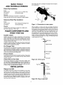
SEARS
OWNER'S
MANUAL
MODEL NO.
390.2509
I:RRFTSMRN°
CAUTION:
Read and Follow
All Safety Rulesand
Operating Instructions
Before FirstUse of
This Product.
Save ThisManual For
Future Reference.
1/2 HP SHALLOW WELL
WATER SYSTEM
• Safety Instructions
• Installation
• Electrical
• Maintenance
• Repair Parts
Sears, Roebuck and Co., Hoffman Estates, IL 60179
PRtNTED
IN U.S.A,
U.S.A.
Form No. F642-04074
(8/3/04)
CONTENTS
INTRODUCTION/WARRANTY
MAJOR
COMPONENTS
INSTALLATION
INTRODUCTION
.....................................................
3-4
..................................................................
ELECTRICAL
...............................................................................
OPERATION
..................................................................................
M.MNTENANCE
4
5_5
7
........................................................................
7-10
HINTS ..........................................................................
11
REPAIR PARTS ........................................................................
TROUBLESHOOTING
GUIDE
12-14
.....................................................
15
READ AND FOLLOW
Carefully
ual or on
_This
read and
pump.
all safety
instructions
is the safety alert symboL
on your pump or in this manual,
ing signal
words
_
sonal
follow
death
r
about
or major
ILazards
property
in this
SAFETY INSTRUCTIONS!
man-
When you see this symbol
look for one of the follow-
and be alert to the potential
warns
injury,
Please read our instructions before installing and using your Shallow
Well Water System. This will help you obtain the full benefits of the
quality and convenience built into this equipment. It will also help
you avoid any needless service expense resulting from causes beyond our control which are not covered by our warranty.
3
..........................................................................
PUMP PERFORMANCE
HELPFUL
2
.................................................................
that
for personal
will
cause
damage
injury!
serious
1.
To avoid risk of serious bodily
read safety instructions
carefldiy
2.
Follow local and/or
national
when installing pump.
3.
Keep well covered
personal
injury,
death
hazards
or major
that will
per-
if ignored.
property
or can
damage
cause
4.
personal
injury
about
or property
hazards
damage
that will
serious
r
[_
installing
and electrical
pump
to prevent
and piping
system
to freeze
could
avoid
serious
leaves and
well and pos-
from freezing.
severely
codes
Allowing
pump
damage
pump
and
and
equipment
if ignored.
or can
cause
LAWARNINGJTo
minor
instructions
which
injury
damage,
limit system
pressure
inch (PSI) or below
at all times.
explosion;
install
relief
valve
pump
volume
at 75 PSI.
if ignored.
The word NOTICE
indicates
special
portant
but not related to hazards.
Protect pump
or water system
voids warranty.
P
[A CAUTION Iwarns
plumbing
other debris from falling into well, contaminating
sibly damaging
pump.
I
[ ..XWARNING ]warns about
while
injury and property
damage,
before installing pump.
are im-
to 75 pounds
Over-pressure
capable
of
per sqlmre
can cause
passing
full
i
CAUTION
[Never
may cause pump
burns to persons
starting.
rtm pump
dry. Running
pump
without
5.
water
to overheat,
damaging
seal and possibly causing
handling
pump.
Fill pump
with water before
With a new well, test well for purity
Health Department
for procedure.
F
before
use. Consult
local
_
LAWARNINGJHazardous
cause death, or start fires.
voltage.
6.
Disconnect
electrical
ing on pump.
source
7.
Ground pump with a ground wire run from grounding
motor to a grounded
lead in the service panel.
8.
Line voltage and frequency
agree with motor nameplate.
9.
Use
Can
shock,
burn,
P
L_k WARNING_ Never
run pump
against closed
discharge.
TO do
so can boil water inside pump, causing
hazardous
pressure
in
unit, risk of explosion
and possibly
scalding
persons
handling
pump.
F
lax CAUTIONJ
Motor
normaUy
operates
at high temperature
and
will be too hot to touch.
It is protected
from heat damage during
operation
by an automatic
internal cutoff switch.
Before handling
pump or motor, stop motor and allow to cool for 20 minutes.
of fuses
owner's
manual
void warranty.
2
or
wire
power
of electrical
smaller
can cause
before
than
overheating,
installing
power
size
or work-
supply
recommended
possible
lug on
must
in
fires, and will
BASIC TOOLS
AND MATERIALS NEEDED
When using a foot valve, a priming
are recommended.
tee and plug as shown
in Figure 1,
Plastic Pipe Installation
Tools
Pipe Wrenches
Knife
Screwdriver
Tire Pressure
or Saw to Cut Plastic
Pipe
Gauge
Materials
Plastic
Pipe and Firings
Teflon
Tape
(as required
(DO NOT
Galvanized
use joint
Steel
to complete
compound
job).
on plastic
fittings).
Pipe Installation
Tools
Pipe Wrenches
Pipe Cutting
and Threading
Screwdriver
Tire Pressure
Gauge
Tools
Figure
I - Connections
to water
system
Materials
Galvanized
Pipe and Fittings
Pipe Joint
Compound
(as required
or Teflon
to complete
When installed
System should
job).
Tape
Impeller
The maximum
lift of any pump decreases
at the rate of about 1'
less lift for every 1,000 feet of elevation
above sea level. For example, at Denver,
Colorado
(Elev. 5,000') the pump loses five feet
of lift. The maximum
depth from which
it would
pump water
would therefore
be 15 feet.
and Jet
causing
rotation
point well, your Shallow Well Water
valve installed as shown in Figure 2A.
For a pump at sea level mounted directly over the well, be sure the
total lift from the pumping
water level to the pump does not exceed 20 feet. This will be less if the pump is offset from the weB.
MAJOR COMPONENTS
AND
WHAT THEY DO
Impeller
turns with motor shaft,
rim by centrifugal
force. Impeller
on a driven
have a check
water to fly out from its
creates
a vacuum which
pulls in more water. Part of the water is diverted
back to the jet
where it passes through the nozzle and venturi. This creates more
vacuum
to draw in more water.
C_heck
Valve
In shallow webs (less than 20 feet deep), the vacuum created at the
pump is enough to pull water to the pump. Therefore,
for shallow
web use the jet is built into the pump.
Pre-Charged
Tank
The tank serves two functions.
It provides
a reservoir
of water
under pressure
and maintains
a cushion of air pressure
to prevent
pipe hammering
and possible
damage to plumbing
components.
When water is drawn off through
the house fixtures, the pressure
in the tank is lowered
and the pump starts.
Pressure
Switch
The pressure
switch
provides
when
pressure
drops
reaches 50 pounds.
for automatic
to 30 pounds
and
operation.
stops
_Steel
_Drive coupling
_Well point
Pump starts
when
pressure
_Ddven
Check Valve or Foot Valve
to web
as possible
(all types
point
Figure 2A - Driven point
This pump is equipped
with a built:m check valve. Install a check
valve as close
to well as possible
on web point installations.
A
foot valve must be installed in the well on dug or cased wells. See
Figures 2A and 2B. For long horizontal
pipe runs, install check valve
as close
Drive Pipe
Well Seal
Plastic PilSe
of wells).
INSTALLATION
Piping
in the Well
The Shallow Well Water System can be installed
on a dug well,
cased well or with a driven point. In a dug or cased well, a foot
valve and strainer should be installed for easy priming. It should be
installed five to ten feet below the lowest level to which the water
Foot Valve
and Strainer
will drop while the pump is operating
(pumping
water level). To
keep sediment
from clogging the strainer, be sure it is five to ten
feet above the bottom of the well. Before installing the foot valve,
make sure that it works freely.
Figure
3
2B - Dug or cased well
INSTALLATION
PUMP/TANK
INSTALLATION
Tank
Pump
NOTICE: Use Teflon tape supplied with the pump or Plasto-Joint Stik _
for making all pipe-thread
connections
to the pump itself. To avoid
stress-cracking,
do not use pipe joint compounds
on the pump.
1.
Wrap male pipe threads being attached
to pump
two layers of Teflon tape. Cover entire threaded
pipe.
2.
Do not overtighten
threaded
fittings in the plastic pump.
Be
sure you do not try to tighten joint past thread stop in pump
port!
3.
If leaks occur, remove fittings, clean off old tape, rewrap
with
two to three layers of tape and remake the connection,
ff joint
still leaks, replace the fittings (fittings may be undersized).
4.
Be sure to support
Horizontal
all piping
connected
with one or
portion
of
check tank pressure
with tire gauge to deterneeds adjustment.
Tank pre-charge
should be
see instructions
at right.
to the System.
1-114"
1-1/2"
2"
Up to 25 Ft.
25 to 50 Ft.
50 to 200 Ft.
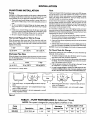
1. Open
faucets
furthest
from
2.
Air in the system will cause
run until you have a steady,
3.
Open and close faucets
been removed.
4.
If stream
tank and allow pump
repeatedly
does not become
NOTICE:
To prevent
To Check
waterlogging,
1"
1-114"
1-1/2"
Up to 25 Ft.
25 to 100 Ft.
100 to 600 Ft.
faucets
air may be leaking into the syson the suction
check
side of the pump.
tank air charge
annually.
Tank Air Charge
available
per cycle)
1.
To check air charge in tank, shut off electric
open faucet near tank, and drain completely.
2.
At the air valve in top of tank, check
decreases
power
air pressure
sig-
to pump,
with standard
tire gauge. Air pressure
should be the same as the turn on pressure of the pressure
switch (30 PSI).
Co., Chicago, IlIinois
3.
If the air pressure
is below 30 PSI, add air to the tank. Use an
air compressor
or a portable
air storage tank.
4.
Use soap or liquid detergent
to check for air leaks around air valve.
Continuous b_
_
a lealc If necessary, install new core in
air valve. This is tiae same as those used for amons3b_le tabeless tires.
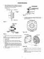
1
x-d
2
Tank nearly
arator.
2.
Water begins m enter tank - air is compressed
rator as it fills with water.
3.
Pump-up cycle completed - air now compressed
setting of pressure switch.
- air expands
L_d
3
1.
filling area above
X_d
"_d
4
5
vinyl sep-
4.
Water being drawn from tank - compressed
water out of separator.
above sepa-
5.
Separator
completely
empty
- new
cycle
tank air forces
ready
to begin.
to cut off
Figure 3
TABLE
to
until you are sure all air has
steady,
If drawdown
(amount
of water
nificantly,
check as follows:
When the pump is some distance from the house or point of water
use, the discharge
pipe size should be increased
to reduce pressure
losses caused by friction.
to operate.
a sputtering
flow; allow
air free stream.
tem; check for leaks in the pipio_
Pipe Sizes
empty
proper
operation;
mine if air charge
checked
annual!y;
It is necessary
to flush aL! air out of the piping system and water
reservoir
portion
of the pre-charged
tank. This is required
on new
installations,
pumps requiring repriming
and pumps that have been
disassembled
for service. Do this as follows:
When the pump is offset more than 25 feet from the well, horizontal suction
pipe size should
be increased
to reduce
friction
losses. Never install a suction pipe that is smaller than the suction
tapping
of the pump.
'Lake Chemical
with 40 pounds per square inch (PSI) air presYour tank requires
an air charge of 30 PSI for
In areas where the temperature
is high for long periods of time, the
tank pre-charge
pressure
may increase.
This may reduce the tank
drawdown
(amount
of water available per cycle). If this occurs, reduce the pre-charge
pressure
to match the pump cut-in setting of
the pressure
switch (normally 30 PSI).
Piping from Well to Pump
Discharge
Tank is pre-charged
sure at the factory.
I - PUMP
PERFORMANCE
(In Gallons per Minute)
NOTE: This system is designedfor pumping depths of 20 feet or less.
Pump
Model
Description
Suct.
Disch,
Pressure PSI
5'
10'
15'
20'
390.2509
112HP S.W. Jet
1-1/4"
3/4"
40
7.3
6.2
5.2
4.2
Discharge
4
Pumping Depth in Feet
ELECTRICAL
Disconnect
Motor
Switch
power
before
working
on pump,
Settings
Dial
motor,
Type
pressure
Voltage
switch,
Selector
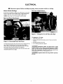
lfthe motor can operate at either 115 or 230 volts, it is set at the
factory to 230 volts. Do not change
motor voltage setting if line
voltage is 230 volts, or if you have a single voltage motor.
NOTICE:
Never
Remove
wire
Motor
a 115 volt
motor
or wiring.
rConnections
to a 230 volt line.
End Cover
Ground Wire Connection
Figure 5 - Voltage Set To 230 Volts, Dial Type
To change to I 15 volts:
1. Make sure power is off.
Figure 4 - Removing
Motor
2. Turn the dial counter-clockwise
window.
End Cover
3. Reinstall
You will need to remove
the motor end cover to change the voltage setting. The illustration
above also shows the pressure
switch. If the power
supply connection
still needs to be made,
the pressure
switch cover v_di need to be removed.
Your
should
motor
terminal
board
(located
look like the one at right.
under
the motor
end cover)
the Motor
4. Go to Wiring
until
115 shows
in the dial
end cover
Connections,
Page 6.
[_,WARNING] Hazardous voltage. Can shock, burn, or kill
Connect
ground wire before connecting
power
supply
wires. Use the wire size (including
the ground wire) specified in the wiring chart. If possible, connect the pump to a sep
arate branch circuit with no other appliances on it.
_
ply line.
Explosion
hazard.
Do not ground
to a gas sup-
ELECTRICAL
WIRING
CONNECTIONS
I _,WARNING_J Fire
hazard.
Connection Procedure:
Incorrect
voltage
can cause
seriously
damage
the motor and voids the warranty.
voltage must be within ± 10% of the motor nameplate
1.
a fire or
The supply
voltage.
apply.
Consult
your
and maintain
your pump in compliance
Code (NEC) or the Canadian
Electrical
and with all local codes and ordinances
local
building
inspector
for code
the ground
wire
wire must be a solid
supply wires.
2.
NOTICE: Dual-voltage
motors
are factory wired for 230 volts. If
necessary,
reconnect
the motor for 115 volts, as shown.
Do not
alter the wiring in single voltage motors.
Install, ground, wire,
the National Electrical
(CEC), as applicable,
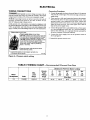
Connect
first as shown
copper
in Figure 6. The ground
wire at least as large as the power
There must be a solid metal connection
between
the pressure
switch and the motor for motor grounding
protection.
If the
pressure
switch
is not connected
to' the motor,
connect
the
green ground screw in the switch to the green ground
screw
under the motor end cover. Use a solid copper wire at least as
large as the power supply wires.
with
Code
that
information.
Motor wires connect here.
-Power supply wires connect here.
230 Volt: Connect 2 hot wires (black and re(
here and cap the white (neutral) wire. It does
not matter which wire goes to which screw.
115 Volt: Connect one hot wire (black or red)
to one of these screws (it doesnl matter
which one). Connect the white (neutral) wire
to the other screw. Cap any remaining
• blackor red wires.
3.
Connect
the ground wire to a grounded
lead in a service panel,
to a metal undergromad
water pipe, to a metal well casing at
least ten feet (3M) long, or to a ground electrode
provided
by
the power company
or the hydro authority.
4.
Connect
the power
shown in Figure 6.
5. Reinstall
the pressure
supply
wires
switch
cover.
to the pressure
switch
power cable to prevent strain
on the terminal screws.
areen (or bare copper) ground wire
to the green ground screw.
Figure 6 - Pressure
31870398
switch wiring
TABLE
II WIRING
CHART
- Recommended
Wire
and Fuse Sizes
Distance in Feet fromMotorto
Max,
Load
Branch
Fuse*
Motor
Horsepower
Volts
Amps.
Rating
Amps
1/2
115/230
10.4/5.2
15/15
0'
to
100'
101'
to
200'
201'
to
300'
Meter
301'
to
400'
401'
to
500'
6/14
6/12
Wire Size
14/14
6
10/14
8/14
as
OPERATION
Priming
To prime
Vinyl
the Pump
NOTICE: To prevent
until pump has been
damage to intemal
filled with water.
do not
start motor
Remove
2.
Fill pump
priming
3.
Replace priming plug, using Teflon
plug threads; tighten
plug.
4.
Start the pump. Water should
repeat steps 1, 2 and 3.
with
plug (Figure
LAWARNINGJ
1, Page 4).
water.
tape or Plasto-Joint
be pumped
I_AWARNING
Stik z on
in 1-2 minutes.
fore
If not,
1.
DISCONNECT
2.
Drain
From 10 to 20 foot depths, you might have to shut offthe
and repeat steps 1, 2 and 3 several times.
4.
Disconnect
several
times,
no water
pump
is pumped,
suction
pipe
B. Be sure
suction
pipe does
Co., Chicago,
Risk
on
is in the water.
not leak.
to lift water
too high (see
shock.
The motor
seal in the
1.
DISCONNECT
POWER.
2.
Open faucet
ceeding.
and relieve
5.
6.
Disconnect
power
be-
unit.
Pump should be drained whenever
or is in danger of freezing.
it is disconnected
all pressure
released
on system
from
14) from pump body
to drain completely,
power
be-
(expel)
to tank.
(Key No. 6, Page
ALL air pressure
outside
piping
14) from tank elbow.
in system
by removing
valve
from tank and pump.
To avoid
serious
or fatal
released
Continue
pulling
before
all
pro*
and dry inside
No. 2, Page 14). Tap inlet
and cutting
7.
Clean
8.
Place replacement
bag on a clean
Flatten bag and force air out.
9.
Tightly
until
bag is removed.
of tank.
roll bag towards
center
surface
with
opening
up.
opening.,
10.
Before center opening
is covered
up, force
ing portion
of bag. Finish rolling bag.
11.
To make bag easier to insert
with talcum powder.
12.
Being careful not to break valve, stand
roiled bag into tank.
13.
Reach into bag and push
all wrinkles.
14.
Clean center
15.
Pull ring on bag through tank opening and fit over tank lip. BE
SURE it seats properly in groove on tank lip.
16.
Clean sealing
17.
NOTICE:
opening
tighten
into tank, sprinkle
out sidewalls.
of inlet flange
C. Tighten
opposite
You need
Recharge
20.
Reconnect
(above).
opposite
and place
on studs.
pairs to a snug fit.
tank to proper
and
Be sure
all nuts
are
you may twist studs off of tank.
tighten to 85 inch-pounds
torque.
tank on feet and reconnect
hoses
not remove
nut snug.
tightening
NOTICE: Do not ovettighten;
If you have a torque wrench,
Stand
of bag
all nuts.
one nut snug.
19.
outside
nuts as follows:
B. Tighten
18.
of remain-
tank on end. PUsh tightly
E. Recheck
all nuts, using same pattern.
tight and you have a good seal.
and
tilt
air out
ring on bag and lip on tank.
surface
Tighten
D. Proceed,
7
be sure
tank
Wherever
convenient,
hold bag with pliers and cut with single-edge razor blade or sharp knife. Bag will not come out in
A. Hand
sys-
injury,
from
6.
pro-
Remove priming plug to vent pump; disconnect
hose (Key No.
6, Page 14) at tank end and drain pressure
tank and aL! piping
to a point below the frost line.
Be sure to drain any piping that may be cut off from normal
tem drain due to check valve installation.
Disconnect
Remove nuts from inlet flange (Key
flange to break seal. Remove flange.
service
before
shock.
5.
Disconnect
pressure
switch
tube (Key No. 15, Page 12) at
barbed elbow on pressure
switch (Key No. 26) and allow tube
to drain.
Unscrew
barbed
elbow (Key No.
allow pump
to drain. If necessary
pump.
been
TO PUMP.
closest
hose
one piece.
Illinois
of electric
has
p
Draining for Winter
working
POWER
air pressure
has been
ceeding
to step 5.
It is not necessary
to lubricate
the pump or its motor.
bearings
are lubricated
for life. The mechanical
shaft
pump is water lubricated
and self-adjusting.
L_'WARNING]
pressure
as follows:
L,_WARNING_
A. Be sure
Chemical
of electric
faucet
Relieve
core.
If, after priming
pump
check the following:
ALL air
unit.
system
3.
Lubrication
4.
on
B. Remove
MAINTENANCE
3.
] Risk
working
A. Open
D. As long as foot valve and check valve function
correctly and
suction pipe does not develop leaks, pump should not need
repriming
in normal service.
fore
Be sure
On shallow depths
to water (10 feet or less), the pump will
probably
prime the first time after following steps 1 through
4
above.
C. Be sure that pump is not trying
"Piping in the Well", Page 4).
2 Lake
Bag Replacement
from tank before
removing
nuts from flange.
Failure to do
this may result
in serious
or fatal injury.
Do not attempt
to
open
tank unless
all pressure
has been relieved_
pump:
1.
5.
parts,
piping.
air pressure
pressure
(see Page 5).
switch
tube;
prime
pump
MAINTENANCE
Air Valve Replacement
1. Follow steps
Page 7.
1 through
2.
5 under
"Vinyl
Push
B. Pick up a small amount of petroleum
jelly on one finger and
spread eveniy over seal plate and venturi O-Ring gasket for
lubrication
during reassembly.
Be careful
not to nick or
tear O-Ring.
Cut valve off as close to tank as possible.
tion back into tank.
3.
Tip tank on end and BE SURE al! water
4.
Ca_efially remove
bag ring from lip on tank opening
and push
bag ring back into tank; reach in mound it and remove cut off
portion of valve from tank.
remaining
is drained
from
5. Wipe a thin film of soapy solution on replacement
from inside tank insert in hole in top of rank.
porbag.
14 through 20 under
bag in tank.
"Vinyl Bag Removal
D. Replace
at
1 through
2. Tip tank on end,
4 under
valve down.
3. If bag leaks, water
structed
above.
of electrical
and power
motor.
disconnected
Your pump
is designed
shock.
before
not to break
If so, replace
Disassemble
pump
A. Disconnect
valve!
attempting
for ease in servicing.
any work
Should
on pump
repair
or re-
tube from
pump
body
to separate
pump
1.
Disassemble
2.
Remove
diffuser
Page 12).
D. Turn
body
and aflow
D. Remove motor, seal plate, impeller,
rubber pad and diffuser
(Key Nos. 1, 3, 7, 8 and 9, Page 12) as a unit. You may have
to pry gently with two screwdrivers
between
the motor
and the pump
Nos.
5 and
3,
tubing
and motor
wiring.
above.
of two parts, a rotating member
and a
of the seal are easily damaged.
Read in-
as follows:
pump
per instructions
and impeller
screws
C. Place 7/16"
and piping
C. Remove
four hexnuts
and lockwashers
(Key Nos. 24 and
23, Page 12) which hold the pump body to the motor.
flange
(Key
to instructions
holding
and motor.
8
impeller
open
above.
as follows
(Key
Nos. 9 and 7,
diffuser.
B. Loosen two screws and remove
(Key No. 1, Page 12).
as follows:
switch
motor
A. Remove
or
power.
B. Remove pressure
pump to drain.
switch
NOTICE:
The seal consists
ceramic
seat. The surfaces
structions
carefully.
bag as in-
Be sure unit is grounded
placement
of the motor or seal be needed,
the pump
do not need to be disconnected
or disturbed.
1.
plate
If it is necessary
to separate
motor and seal plate, always replace
the shaft seal. We suggest you purchase
this item, U109_6A, and
have it on hand for future use.
Bag Replacement",
Remove
{_,_WARNING]
seal
°, Page
AND
OF PUMP
Risk
_VinyI
Be careful
ASSEMBLY
on
Removing
Motor for Service
and Replacing Shaft Seal
will run out of valve.
DISASSEMBLY
pressure
E. Prime pump according
F. Check for leaks.
Testing for Bag Leakage
1. Follow
steps
Page 7.
gasket
C. Replace motor onto pump body; be sure rubber pad (Key
No. 8, Page 12) stays in place on top of diffuser. Remount
base on lower studs. Tighten four hexnuts and lockwashers
snugly (35-45 inch-lbs, torque).
Do not overtighten.
valve and
Pull valve through hole with pliers or a valve tool (available
your local filling station or Automotive
Center).
7. Follow steps
7, to reinstall
of pump:
Bag Replacement",
2.
6.
Reassembly
A. Install O-Ring
Page 12).
end wrench
cotmterclockwise
motor canopy
on motor
when
from motor
shafx flat.
facing
it.
MAINTENANCE
3.
Remove seal plate from motor by inserting
two screwdrivers
between
the seal plate and the motor flange. Pry seal plate off
motor flange. This will force rotating portion
of seal off shaft.
NOTE:
Be sure you do not
scratch
/
,_:/./_
shaft!
POLISHED SURFACE
OF FLOATING SEAL
See Figures 7 & 8.
MOTOR FLANGE
ER
HALF
//_
3/4" PIPE
CUP SEAL _
......
Figure 9
F.
Reassemble
seal plate to motor
up: index pins should be down;
Figures 10A and lOB.
TOP OF MOTOR
flange. BE SURE it is right side
seal plate is marked at top. See
FLANGE
Figure 7
COPPER SEAT
SEAL PLATE INDEX PINS
SLIDE IN HERE
FLOATING
SEAT
Figure
I 0A
MEMBER
Figure 8
MOTOR FLANGE
4.
Place
seat.
seal plate
face down
NOTICE: Do not force
will occur. See section
6.
Clean seal cavity.
InstaLl new seal.
A.
Clean
B.
Wet outer
solution.
5.
C,
polished
of ceramic
of cup seal with
seat with
petroleum
clean
cloth.
jelly or detergent
With finger pressure,
press firmly and squarely
into cavity.
Polished
face of seat faces inside of pump. If seat will not locate properly,
place cardboard
washer over polished face and
use piece of 3/4" standard
pipe for pressing
purposes.
See
Figure 9.
D,
Dispose
E.
Clean motor
of cardboard
SEAL PLATE
and tap out ceramic
out copper insert, ff it has moved, leakage
on installing copper
insert on Page 10.
surface
edge
on flat surface
washer
and dean
surface
iNDEX PINS
Figure I 0B
of seat.
shaft.
G,
H.
Apply detergent
member.
solution
diameter
of rotating
seal
Slide rotating member on shaft untO rubber drive ring tOts shaft
shoulder.
NOTE: Be sure you do not
shoulder
or seal will leak!
9
to inside
chip
or scratch
seal face on shaR
MAINTENANCE
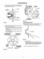
Screw impeller
on shaft (clockwise)
while holding
shaft with
7/16" open end wrench
on shaft flats. This will automatically
locate seal in place. See Figure 11.
I*
SEAL
PLATE
HOLES MUST
LINE UP
DIFFUSER
FACE OF
SEALING WASHER
SHAFT
SHOULDER
BE SURE NIBS
ENGAGE NOTCHES
RUBBER DRIVE RING
Figure
Figure
Installing
II
NOTE:
during
J.
Remount
dittuser on seal plate. Be sure
up as follows (see Figures 7 and 8).
a.
Rib next
to priming
b. Part number
ten o'clock.
c.
13
hole should
(N1-28P)
Both mounting
screws
plate. See Figure 12.
should
must
d. Be sure rubber pad (Figure
place on top of diffuser.
BE SURE RUBBER PAD
STAYS IN PLACE ON
diffuser
is right
be at six o'clock
be between
engage
holes
Insert
Remove
copper
insert
as shown
in Figure
or shifts
14. do not deform.
position;
nine o'clock
screw
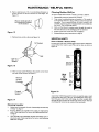
1.
side
Copper
If the copper
insert (Key No. 4, Page 12) moves
seal removal,
it should be removed and reinstalled.
and
in seal
12; Key No. 8, Page 12) stays in
TO DISASSEMBLE
BE SURE SCREW
ENGAGES HOLE IN
SEAL PLATE
Figure
2.
14
Replace
copper
insert:
A. Clean off surplus Permatex* from around insert cavity. Be
careful not to scratch or mark the machined
bore. It is im-
MOLDED
PART NO,
AT9:3O
O'CLOCK
RIBAT 6 O'CLOCK
Figure
portant
behind
BESURESCREW
ENGAGES HOLE
IN SEALPLATE
PRIMING
* "Permatex"
HOLE
12
10
that this area be clean so no old Permatex
the new insert and causes improper
seating.
is a registered trademark of Permatex Co. Inc,
lodges
MAINTENANCE
/ HELPFUL
B. Place a small amount of No. 2 non-hardeding
Permatex
surface
of insert as shown.
Smooth
out with finger.
Figure 15.
on
See
Cleaning
To remove
Figure
debris
Disassemble
2.
Turn.venturi
Well
from venturi
pump
Jet
or nozzle,
per instructions
counterclockwise
proceed
as follows:
on Page 8.
and remove
it. The
nozzle
is
now exposed.
Remove it using a 5/8" hex socket wrench with
extension.
Turn counterclockwise.
If socket wrench
is not
available, insert an ice pick or similar pointed
the nozzle. This will dislodge debris.
15
C. Pull insert
Shallow
1.
Wipe on small amount of
non-hardening Permatex
on this surface
HINTS
into cavity as shown
in Figure
tool carefully
3.
Flush out the debris by running water through
the nozzle
the same direction
as the dislodging
tool was inserted.
4.
Replace
5.
Reassemble
nozzle
and venturi.
per pump
into
in
Do not overtighten!
instructions
on Page
8.
16.
HELPFUL
HINTS
How to Handle a Gaseous Well
In some areas well water contains
escape before
the water is used.
Figure 18.
gases which must be allowed
This can be done as shown
to
in
Socket
"Bo,,
Figure
wire to hold
pipe sleeve
16
D. Clean OUt any surplus
Permatex
from Insert
new seal will be located. See Figure 17.
Remove
cavity
where
Not
to
L_
SUrrP/US
pipe
vaJve
Scale
f_
2369 0396
sleeve
cap
ProperlyJ
Seated °
Figure
Figure
A good way of delivering
gas-free water is to suspend a pipe, closed
at the bottom
and open at the top, surrounding
the suction pipe.
Since the gases rise in the well casing, the water sucked
down
",_
I7
Cleaning
18
through
the pipe and into the suction
of well must be vented to the outside
Impeller
1.
Follow steps 1A through
of Pump _ on Page 8.
1D under
"Disassembly
and Assembly
2.
Remove
diffuser
tinder "Removing
on Page 8.
3.
Clean impeller
and reassemble
impeller
and diffuser per instructions
under "Removing
Motor for Serivce and Replacing
Shaf_ Seal" on Page 8.
and impeller
from pump
per instructions
Motor for Service and Replacing
Shaft Seal"
11
pipe is free of gas. This type
of any enclosure.
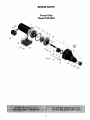
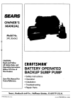
REPAIR PARTS
Pump Only
Model 390.2509
28
27,
2
4
6
8
9
10
26
11
25
/
24
23
\
22
AVC
Port
21
20
19
18
17
2305 0296
/
13
12
/
12
J
12A
/
12B
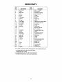
REPAIR PARTS
Key
No,
Par[ Number
Qty.
Used
Description
1#
J218-953C
1
Motor - 115/230V
2
3*
4
C69-2
N203-12P
J3-2
1
1
1
Water Slinger
Seal Plate Assembly
Seal Plate Insert
5
6
U9-390
2784
1
1
O-Ring
Shaft Seal
7
8
9
J105-40PF
C35-41
N1-28P
1
1
1
Impeller
Rubber Pad
Diffuser
10
11**
12
12A
12B
U30-738SS
N176-35PE
N76-35PE
U9-226
N 166-5P
2
1
1
1
1
Capscrew #10-16 Hex Head
Pump Body Assembly
Pump Body
O-Ring
Check Valve
13114t
15
16
U37-670P
J20-18
1
1
1
1
Pipe Plug 1/8" NPT
90 ° Hose Barb
Pressure Switch Tube
Gasket
17
18
19
20
N76-29P
U30-742SS
N34P-19
N32P-66
1
4
1
1
Pump Body Jet Insert
Capscrew #10-16
Nozzle #45
Venturi
21
22
23t
24t
25
U9-201
J104-9F
1
1
4
4
1
O-Ring
Base Assembly Painted
Lock Washer 3/8"
Nut 3/8" - 16
Rubber Pad
26
27t
28
2781
1
1
1
Pressure switch
Locknut 1/2"
Connector 1/2"
C35-5
L43-5C
# For repair or service to motors, always give the motor model number and
any other data found on the motor model plate.
* Includes Key Nos. 4 and 5.
** Includes Key Nos. 12, 12A, 12B, and 16 through 21.
t Standard hardware item, may be purchased locally.
]3
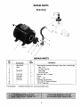
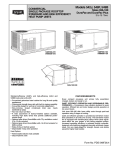
REPAIR PARTS
Tank Only
9 ----_Q
/
2433 0596
2
3
4
REPAIR PARTS
Key
No.
1
"t
2
3t
4
5
6
7
819t
• Not illustrated,
Pad Num_r
U231-285-S
U20-7
I
U31-442P
I
U78-770P
U 19-55SS
U74-37X
U78-972P
I
Qty.
Used
1
1
1
1
6
1
2
1
1
1
1
Description
Tank Assembly (Includes Diaphragm, Valve, Nuts, & Inlet Flange)
Bag - Vinyl
Air Valve with Cap
Inlet Flange
Nut 5/16-18 Hex
Elbow 3/4" MPT x 1" Insert
Clamp
Hose - 1" x 23"
Discharge Tee with Barb
1/2" x 1/8" NPT Reducer Bushing
1/8" NPT Pipe Plug
t Standard hardware item, may be purchased locally.
14
TROUBLESHOOTING
TROUBLE
Motor will not run
Motor runs hot and
overload kicks off
Motor runs but no
water is delivered
(*Note: Check
prime before looking for other
causes. Unscrew
priming plug and
see if there is water
in priming hole)
POSSIBLE
CAUSES
1. Disconnect switch is off
2. Fuse is blown
3. Starting switch is defective
4. Wires at motor are loose,
disconnected, or wired incorrectly
5. Motor is wired incorrectly
6. Pressure switch contacts are dirty
GUIDE
REMEDIES
1. Be sure switch is on
2. Replace fuse
3. Replace starting switch
4. Refer to instructions on wiring
5. Refer to instructions on wiring
6. Clean by sliding piece of plain paper between contacts
"1. Motor is wired incorrectly
2. Voltage is too low
3. Pump cycles too frequently
"1. Pump in a new installation did
not pick up prime through:
a. Improper priming
b. Air leaks
c. Leaking foot valve
*2. Pump has lost its prime through:
a. Air leaks
b. Water level below suction of pump
3. Jet or impeller is plugged
4. Check valve or foot valve is stuck
in closed position
5. Pipes are frozen
1. Refer to instructions on widng
2. Check with power company. Install heavier wiring
if wire size is too small. See wiring instructions
3. See section below on too frequent cycling
1. In new installation:
a. Re-prime according to instructions
b. Check all connections on suction line and jet
c. Replace foot valve
2. In installation already in use:
a. Check all connections on suction line, jet and shaft seal
b. Lower suction line into water and re-prime. If receding
water level in a shallow well operation exceeds
suction lift, a deep well pump is needed
3. Clean jet or impeller according to instructions
4. Replace check valve or foot valve
5. Thaw pipes. Bury pipes below frost line. Heat pit or
pump house
6. Raise foot valve and/or strainer above well bottom
6. Foot valve and/or strainer are
buried in sand or mud
Pump does not
deliver water to full
capacity (also check
point 3 immediately
above)
1. Water level in well is lower than
estimated
2. Steel piping (if used) is corroded or
limed, causing excess friction
3. Offset piping is too small in size
Pump pumps water
but does not shut off
1. Pressure switch is out of adjustment
or contacts are "frozen"
2. Faucets have been left open
3. Jet or impeller is clogged
4. Motor is wired incorrectly
5. Water level in well is lower than
estimated
1. A deep well jet pump may be needed (over 20 ft. to water
2. Replace with Plastic Pipe where possible, otherwise with
new steel pipe
3. Use larger offset piping
1. Adjust or replace pressure switch
2.
3.
4.
5.
Close faucets
Clean jet or impeller
Refer to instructions on wiring
Check possibility of using a deep well jet pump
Pump cycles too
frequently
1. Pipes leak
2. Faucets or valves are open
3. Foot valve leaks
4. Pressure switch is out of adjustment
5. Air charge too low in
Captive Air_ Tank
1. Check connections, replace pipe fittings
2. Close faucets or valves
3. Replace foot valve
4. Adjust or replace pressure switch
5. Disconnect electrical power and open faucets until all
pressure is relieved. Using automobile tire pressure
gauge, check air pressure in tank at the valve stem
located at top of tank. If less than 30 pounds, pump air
into tank from outside source, until 30 pounds pressure
is reached. Check air valve for leaks, using soapy
solution, and replace core if necessary
Air spurts from
faucets
1. Pump is picking up prime
2. Leak in suction side of pump
3. Well is gaseous
4. Intermittent over-pumping of well
1. As soon as pump picks up prime, all air will be ejected
2. Check suction piping, make sure joints are not sucking air
3. Change installation as described in manual
4. Lower foot valve if possible, otherwise restrict discharge
side of pump
15
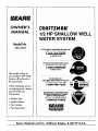
SEARS
OWNER'S
MANUAL
I:RRFTSMRN°
1/2 HP SHALLOW WELL
WATER SYSTEM
Model No.
390.2509
Forthe repair or replacementparts youneed
Call7 am - 7 pro, 7 days a week
t -800-366-PART
(1-800-366-7278)
Forin-homemajorbrandrepair service
Call24 hoursa day,7 days a week
1-800-4-REPAIR
(1-800-473-7247)
The model number of
your Shallow Well Water
Systemwill be found on
the pump body.
When requesting service
or ordering parts, always
give the following
information:
• Product Type
• Model Number
• Part Number
Forthe locationof a
SearsRepairServiceCenterin yourarea
Call24 hours a day,7 days a week
1-800-488-1222
Forinformationon purchasinga Sears
MaintenanceAgreementor to inquire
aboutan existingAgreement
call 9 am - 5 pm, Monday-Saturday
1-800-827-6655
SEARS
• Part Description
America'sRepair Specialists
Sears, Roebuck and Co., Hoffman Estates, IL 60179
U.S.A.