1
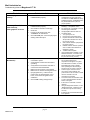
Merit Industries Inc.
Troubleshooting Guide for Megatouch™
XL
Refer to the list below if you are experiencing a problem with your Megatouch XL Game…
PROBLEM
No Power, Game
reboots/monitor seems to
power cycle
CORRECTIVE ACTION
•
•
•
•
•
No Video.
•
•
•
“BOOT ERROR - INSERT
DISC IN DRIVE A,”
“OPERATING SYSTEM NOT
FOUND,”
“SYSTEM BOOT FAILURE.”
•
•
•
•
•
Check that the power cord is connected to a
“live outlet.”
Check that the Power Switch is turned “ON.”
Check that the power cord is connected to
the game power supply.
Check that the power supply’s voltage
select switch is set to the proper voltage.
Check that the game is powered and turned
“ON.”
Check that the monitor is connected to the
game motherboard.
Check that the power is connected to the
monitor and the motherboard.
Make sure the RAM SIMMs is properly
seated.
Make sure that the I/O board is correctly
installed and seated.
Make sure that the riser card is correctly
installed and seated.
Check EPROM chips. Make sure it is
installed and seated.
Check that no EPROM pins are bent.
Make sure that the JP1 jumper is shorted.
COMMENT
•
•
•
•
•
•
•
•
•
•
•
Game starts in cleaning or
Troubleshooter mode when
first turned on.
•
Switch DS2-2 or DS2-1 is set in the wrong
position.
•
“ERROR - INVALID KEY”
•
Check the Dallas Key. Verify that it is
installed and not damaged.
Verify that the CD is the most recent
version.
•
•
•
“FAILURE DRIVE F,”
“BAD FILE COMMAND,”
“FILE NOT FOUND,”
Unit comes on but no game
is displayed.
•
•
Check that the game CD is installed. (CD
must be installed with label UP.)
Check the cable connections to CD-ROM
drive (both ends). Re-seat if necessary.
•
•
•
“Live outlet” is an outlet powered with
electricity.
The power switch is located in the rear
of the game.
The power cord is plugged into the
power supply inside the game.
See “No Power” under “PROBLEM”.
The monitor connection is located inside
the rear compartment of the game.
The monitor is powered from a
connection on the game power supply,
located inside the rear compartment.
I/O board is the small printed circuit
board in the CPU section of the game.
Board must be fully inserted in its
socket.
Riser card is the printed circuit board
connecting the I/O board to the
motherboard. Riser card must be fully
inserted in the socket.
The EPROM is the IC chip installed in U12
socket on the I/O board. EPROM must be
fully inserted in the socket.
Bent pins on the EPROM result in
unreliable contact with the circuit.
JP1 is located near U3 on I/O board.
Install hardware jumper in JP1.
DS2-2 is located on the I/O Circuit Board
in the back of the game. All switches
(DS2 & DS3) should be UP for normal
game operation.
The Dallas key is located near DS2 &
DS3 on the small circuit board inside the
rear of the game. It is a black box
approx. 3/4-inch square. Make sure that
all pins are properly connected between
the key and the board.
The R2/R3 CD will automatically
reprogram the Dallas key for the latest
version. Afterwards, the key will no
longer work with older versions of game
CDs (the R5 CD will not reprogram the
key).
Game CD must be installed for operation.
If CD-ROM drive cables are not
completely connected, CD-ROM will not
operate.
Run the “Motherboard Tests,” using the
diagnostics software, to make sure the
motherboard is working properly.
For more information contact Merit Customer Service at 1(800) 445-9353, 8:30 AM - 6:00 PM EST
page: 1
PM0076-01-0A
Merit Industries Inc.
Troubleshooting Guide for Megatouch™
PROBLEM
Game displays an error with
memory.
“Causeway Error #9,”
Game locks up,
Game graphics incorrect.
XL
CORRECTIVE ACTION
COMMENT
•
Check that the RAM SIMMs is
installed/seated properly.
•
•
Check that the RAM SIMMs is
installed/seated properly.
Check CD for scratches or damage.
Clean CD.
Perform a Two-button clear. See
“COMMENT” for instructions.
Check NV RAM (U11 on I/O card) for proper
seating and/or bent pins.
•
•
•
•
•
•
•
•
•
Touchscreen does not work.
(Microtouch)
•
•
•
•
•
•
•
Verify that the Touchscreen controller is
connected to power.
Verify that the Touchscreen controller is
operating.
Verify that the Touchscreen controller is
connected to the motherboard.
Make sure the screen is not scratched.
Make sure no metal is touching the screen.
Upright games only - make sure the
monitor door is closed properly. If it is
loose, it can cause the game to lose
calibration.
Check COM1 setting during boot-up.
•
•
•
•
•
•
The SIMMs is located on the
motherboard in the rear of the game.
Two 4MB or one 8MB SIMMs are factory
installed in the game. The SIMMs must be
fully seated and locked in place for
proper operation.
See “Game displays an error with
memory” in the problem column.
Dirt, fingerprints, or scratches on the CD
will cause game malfunction.
Use appropriate method to clean CD.
Two Button Clear:
1. Turn game power off.
2. Remove the coin box/bill acceptor.
3. Depress and hold the Calibrate and
Set-up buttons located in the rear of
the coin box opening.
4. With Calibrate and Set-up depressed,
turn game power on.
5. Release Calibrate and Set-up buttons
when “2-Button Clear Detected” is
displayed on screen.
6. “2-Button Clear Complete”
Using the diagnostics software, run the
“Motherboard Tests,” “Processor Test”
and “Co-Processor Test” to make sure
they are each working correctly.
The touch screen controller is a small
box mounted inside the rear
compartment of the game. On a game
with a Microtouch controller, an LED is
illuminated when power is applied.
When operating the LED will change
intensity when the screen is touched.
Check for proper connection of the
touch screen power lead with the
power harness. The connection is made
near the controller in the rear
compartment of the game.
The Touch Screen is connected to COM
1 input on the motherboard in the CPU
section of the game.
If the screen is scratched, it must be
replaced.
Using the diagnostics software, run the
“Motherboard Tests,” “Serial Port Test”
to make sure they are each working
correctly.
If COM1 is bad, the motherboard needs
to be replaced.
For more information contact Merit Customer Service at 1(800) 445-9353, 8:30 AM - 6:00 PM EST
page: 2
PM0076-01-0A
Merit Industries Inc.
Troubleshooting Guide for Megatouch™
PROBLEM
Touch screen does not work
“ELO Graphic”
CORRECTIVE ACTION
•
•
•
•
Poor picture quality.
Game not recording credits
from coins,
Bill acceptor not working.
XL
•
•
•
•
•
•
COMMENT
U12 on the I/O board must be revision R2
or higher
Check the screen for any objects that may
be stuck to it.
Check connections on the controller
Check that the gasket on the bezel is not
dry
Adjust Brightness, Contrast, Horizontal,
Vertical controls
•
Check that the Coin Box/Bill Acceptor is
correctly installed.
Check that the wiring harness on the Coin
Box/Bill Acceptor is intact and not damaged.
Check that the Bill Acceptor is powered.
Check the actuator wire on the coin mech
micro switch.
Check that JP3 (on the I/O board) is shorted
correctly.
•
•
•
•
•
•
•
•
Meter not advancing.
•
Check connection at I/O board.
•
•
No sound,
Game volume low.
•
•
Adjust volume control.
Make sure speaker is plugged in.
•
Game volume loud,
Sound distorted.
•
Turn volume down.
•
Slow loading from CD
player
•
•
•
•
Clean CD
Clean the lens in the CD player
Replace the CD player
Check the U11 on the I/O board for bent
pins.
JP2 on the I/O board should be shorted.
•
99 Credits when the game is
turned on
•
•
LED on the control box will flash, then
stay on steady when the screen is
touched.
Anything stuck to the touch screen will
cause it not work.
Monitor controls are located in the rear
compartment of the game.
Using the diagnostics software, run the
“Video Tests” too fully test all aspects of
the monitor performance.
Coin Box/Bill Acceptor must be fully
inserted and locked into place.
Inspect the wiring harness on the Coin
Box/Bill Acceptor for damage. Make
sure that it is fully connected.
Bill Acceptor (only) requires a power
connection from the power supply. This
power connection is the same plug that
is used to power the monitor. There is a
second connector (two conductors)
behind the Coin Box/Bill Acceptor
connector. Both connections must be
complete for proper operation.
The actuator wire is the thin wire at the
end of the coin chute.
Jumper JP3 (on the I/O board) should be
shorted in the negative position.
Check wiring at J3 METER connector
on I/O board in rear compartment.
Speaker magnet may interfere with the
meter. If you believe this to be the case,
the meter must be replaced.
Volume control is VR1 & VR2 on the I/O
board.
Speaker connection is the small
connector (J9) next to the larger white
connectors on the I/O board.
Volume control is VR1 & VR2 on the I/O
board (and, on front-access, upright
models, an auxiliary volume control is
located on the front of the PC shelf).
•
For more information contact Merit Customer Service at 1(800) 445-9353, 8:30 AM - 6:00 PM EST
page: 3
PM0076-01-0A