1
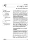
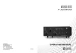
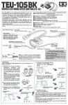
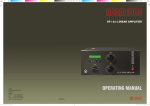
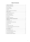
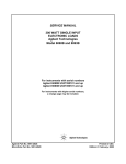
Exhibit 8
1 -17
International, Inc.
Exhibit 8: User’s Manual
External Radio Frequency
Power Amplifier ACOM 1000
Model 1000
157 Horse Pond Road, Sudbury, MA 01776
Tel:
(978) 440-7555
Fax:
(978) 440-9080
e-mail:
[email protected]
1
Exhibit 8
2 -17
TABLE OF CONTENTS
1. GENERAL INFORMATION ..............................................................................................................................2
1-1. INTRODUCTION AND DESCRIPTION .....................................................................................................................2
1-2. OWNER ASSISTANCE .........................................................................................................................................2
1-3. EQUIPMENT SUPPLIED .......................................................................................................................................3
1-4. FEATURES.........................................................................................................................................................3
1-5. SAFETY CONSIDERATIONS, EXPLICIT DEFINITIONS .............................................................................................3
2. INSTALLATION................................................................................................................................................4
2-1. UNPACKING AND INITIAL INSPECTION ................................................................................................................4
2-2. LINE VOLTAGE SELECTION................................................................................................................................4
2-3. AMPLIFIER LOCATION SELECTION .....................................................................................................................4
2-4. CONNECTIONS ..................................................................................................................................................5
2-5. INSTALLATION OF EXTERNAL FAN .....................................................................................................................6
3. POWER ON, CONTROLS AND INDICATORS.................................................................................................6
4. OPERATION......................................................................................................................................................8
4-1. TURNING ON AND OFF.....................................................................................................................................8
4-2. CHANGING OPERATE AND STANDBY MODES ......................................................................................................9
4-3. TUNING ............................................................................................................................................................9
4-4 ON LINE INFORMATION SCREENS AND CONTROL FUNCTIONS. ......................................................................... 11
4-5 AUTO-PROTECTION SYSTEM............................................................................................................................. 11
5. OFF LINE OPERATION .................................................................................................................................. 11
5-1 CONTRAST AND BACKLIGHTING CONTROL ........................................................................................................ 12
5-2 AUTO-OPERATE ENABLING AND DISABLING ...................................................................................................... 12
5-3. READING AUTO-PROTECTION SIGNATURES ...................................................................................................... 12
6. MAINTENANCE.............................................................................................................................................. 12
6-1. CLEANING ...................................................................................................................................................... 12
6-2. FUSES REPLACEMENT ..................................................................................................................................... 12
6-3. TUBE REPLACEMENT....................................................................................................................................... 13
6-4. THE ACOM1000 SIMPLIFIED SCHEMATIC DIAGRAM ........................................................................................ 14
6-5. TROUBLESHOOTING ........................................................................................................................................ 15
7. SPECIFICATIONS ........................................................................................................................................... 15
7-1. PARAMETERS .................................................................................................................................................. 15
7-2. FUNCTIONS ..................................................................................................................................................... 16
7-3. STORAGE AND SHIPMENT ................................................................................................................................ 16
1. GENERAL INFORMATION
1-1. Introduction and Description
This manual explains the installation, operation, and maintenance of the ACOM1000 HF+6 meters linear amplifier.
The ACOM1000 is a complete and self-contained linear amplifier that covers all amateurs bands from 1.8 through
54MHz and provides over 1000W-output power with less than 60W-exciter drive. Antenna VSWR up to 3:1 is acceptable
at full power. Tuning is substantially simplified by a plate-load True Resistance Indicator (TRI) and by an automatically
controlled input attenuator. Operating parameters are displayed by a multi-functional backlighted Liquid Crystal Display.
Full break-in transmit/receive switching (QSK) is standard.
1-2. Owner Assistance
If assistance is needed, you should contact your local dealer first. If you still have an issue you need to discuss with one
of ACOM's specialists, the contact information is as follows: fax + 359 2 230 116, tel. + 359 2 229 147, e-mail
[email protected] or by mail: bul. Gornobanski Nr.151, 1330 Sofia, Bulgaria.
2
Exhibit 8
3 -17
1-3. Equipment Supplied
The ACOM1000 amplifier and this manual are shipped in a cardboard carton.
1-4. Features
• Easy to operate. The TRI is a powerful tuning aid which, together with the automatically controlled input attenuator,
helps the operator to quickly and precisely match antennas (5-10 seconds typically). The auto-operate function (when
enabled) maintains the amplifier in OPERATE mode for you, thus saving manual operations and time.
• No heavy outboard antenna tuners required for antenna VSWR up to 3:1 (and higher on some bands). Your
amplifier will perform the functions of an antenna tuner, thus enabling you change antennas faster and use them over a
wider frequency range (saving tuning time).
• An amplifier that is both user-friendly, and that looks after itself. It is designed to safely withstand up to 500W
reflected power, up to 100 milliseconds duration of drive spikes, drive RF "tails" after a PTT or KEY release, operator's
inadvertent tuning errors etc. It would also not cease to function with a "soft" AC line and would deliver more than half
power at only 75% of nominal mains voltage. It would withstand up to 10 milliseconds (down to zero) voltage drops, and
up to +15% line voltage spikes, which is important particularly when used at field days, Dxpeditions, and other portable
events.
• LCD comment display. All amplifier status indications are explained via detailed text displayed on the dot matrix
backlighted liquid crystal display (LCD). The upper-line’s strip on the LCD always reads directly peak forward power. For
OPERATE, attenuator-on, and ON/OFF conditions are provided LED indicators.
• Easy maintenance. Signatures of the amplifier internal status are stored in a nonvolatile memory for 7 most recent
auto protection trips. This information can be forwarded to your dealer for diagnostics. Using an EXCEL APPLICATION
(available from ACOM or your dealer free of charge) and a PC you can decode the signatures by yourself too.
• Less noise in the shack: the input bypassing and the vacuum antenna relays are virtually silent even in QSK CW
mode due to their special mounting.
• Less QRM and improved Electro Magnetic Compatibility during tuning. Antenna matching can be achieved in less
than 10 seconds at a quarter of nominal output power.
• Operates without special signals from the transceiver - "ground on TX" and 60W RF drive power are sufficient.
• Broadband input matching circuit resulting in very good load to the transceiver over the entire spectrum from
1.8MHz up to 54MHz.
• Uses a single 4CX800A (GU74B) Svetlana high-performance ceramic-metal tetrode with plate dissipation of 800W
(forced air cooling, grid-driven).
• Permanent monitoring and protection of plate and grid voltages and currents, as well as of the exhaust air
temperature. The Bias Optimizer decreases the heat dissipated from the tube, and there is automatic protection against
overheating in accordance with the specifications of the tube producer.
• An output RF Arc protection is employed. It safeguards the amplifier, antenna, antenna selector, and tuner against
severe damage in case of possible break down.
• High voltage power supply inrush current protection, which eliminates the danger of affecting sensitive devices,
connected to the same mains circuit (important when used portable). The amplifier can be configured for 5 nominal line
voltages: 200, 210, 220, 230, and 240VAC, 50 or 60Hz (100, 110, and 120VAC on request).
• Continuous measuring and/or selectable monitoring of 12 most important parameters of the amplifier, exciter and
antennas via LCD.
• The amplifier can be shipped with 10 and 12 meters capability disabled as required by the FCC for US users.
Contact your dealer about enabling those bands.
1-5. Safety Considerations, Explicit Definitions
The ACOM1000 HF+6 meters Linear Amplifier is a Safety Class I unit. The third grounding lead of its mains cord (which
is colored yellow with two green stripes) and the ground stud on the rear panel of the amplifier, (marked GND) must be
connected to the station's grounding system for safe operation.
The amplifier is designed to meet international safety standards and complies with CE safety and electromagnetic
compatibility requirements, as well as FCC regulations.
This operating manual contains information, precautions, indications for cautions and warnings which must be followed
by the user to ensure safe operation and to keep the ACOM1000 in safe operating condition.
PRECAUTIONS:
The EXPLICIT DEFINITIONS described below apply to this operating manual:
W A R N I N G notes call attention to a procedure which, if not correctly performed, could result in personal injury, fire
hazard or electric shock.
3
Exhibit 8
4 -17
C A U T I O N notes call attention to a procedure which, if not correctly performed, could result in equipment damage,
not only in the amplifier.
N O T E notes call attention to a procedure which, if not correctly performed, could result in inconvenience.
W A R N I N G HIGH VOLTAGE!
The amplifier works with high voltages up to 3000V, which are LETHAL! Also, for your safety, pull the amplifier power
plug out of the mains wall outlet and WAIT AT LEAST 30 minutes EACH TIME BEFORE you remove the cover of the
amplifier. Do not touch any part inside while the amplifier is open because some residual voltages may still be present.
W A R N I N G HIGH VOLTAGE!
NEVER ALLOW ANYONE, ESPECIALLY CHILDREN,
to push anything into holes in the case - this will cause electric shock. NEVER TOUCH AN ANTENNA during
transmission - this may result in an electric shock or burn. NEVER EXPOSE the amplifier to rain, snow or any liquids.
AVOID placing the amplifier in excessively dusty environments or in direct sunlight. DO NOT OBSTRUCT AIR INTAKE
(rear panel) and EXHAUST (top cover) areas of the amplifier. Keep a minimum distance of 10cm (4 inches) to the intake
and 50cm (20 inches) to the exhaust.
WARNING
Do not undertake on your own repairs or changes in hardware or software of the amplifier. Otherwise you may endanger
your or other's health and life or damage the amplifier and the equipment connected with it, not covered by warranty.
The manufacturer is not liable for another's actions and responsibility shall be assumed by the doer.
CAUTION
To avoid damage (not covered under warranty) read the Installation - Section 2 of this operating manual carefully. If you
have any doubts about the installation, operation or safeties of the amplifier please consult your dealer.
2. INSTALLATION
2-1. Unpacking and Initial Inspection
NOTE
Before you start to install the amplifier, thoroughly read this manual. First, carefully inspect the cardboard carton and its
contents for physical damage. If damage is noticed, notify your dealer immediately. Delay may infringe carrier's warranty
conditions. Keep all packing for possible future transportation!
2-2. Line Voltage Selection
CAUTION
To avoid damage (not covered under warranty), check carefully if the voltage for which the amplifier is set corresponds
to your mains nominal voltage.
Normally the amplifier is supplied set for a nominal line voltage of 240V. There might be exceptions in cases of special
delivery and then the voltage set is noted in the Table of Individual Data (Table 2-1). If your power line has a different
nominal voltage, it will be necessary for you to contact your dealer.
AMP s/n
Tube s/n
Voltage Selector
VAC
TABLE 2-1. ACOM 1000 INDIVIDUAL DATA
2-3. Amplifier Location Selection
4
Exhibit 8
5 -17
CAUTION
The weight of the unit is about 18kg, which should preferably be handled by two persons.
Position the amplifier near the place where it will be used. You'll need an easy access to the command knobs and
indicator's area, as well as to the rear panel cabling.
No magnetic-field sensitive devices should be located next to the right side of the amplifier as its power transformer is
located there. It's best to position it to the right of your transceiver. No temperature sensitive devices should be located
above the exhaust hot air area, so don't push it under a shelf. You may prefer to use the bottom scales of both variable
capacitor knobs (TUNE and LOAD) if you install it on a shelf. DO NOT OBSTRUCT AIR INTAKE (rear panel) and
EXHAUST (top cover) areas of the amplifier. Keep a minimum distance of 10cm (4 inches) to the intake and 50cm (20
inches) to the exhaust.
2-4. Connections
Connection to your station must be accomplished in the order described below, before you apply mains voltage to the
amplifier.
WARNING
Note that the grounding system may have to withstand currents over 10A with insignificant voltage drop on it. Therefore,
it may be necessary to improve it considerably, i.e. to become less resistive, with heavier leads and lower-resistive
ground path. The grounding leads should be at least 4mm2 (AWG 11 or SWG 13).
Fig.2-1 Connections
a) First, connect the ground stud of the amplifier (on the rear panel, marked GND) to the station's grounding system
(Fig.2-1).
b) Connect a coaxial cable with a PL-259 plug from the transceiver output to the amplifier rear panel RF INPUT socket.
CAUTION
If this is the first time you will use a power amplifier in your station, pay attention to the coaxial cable type from the
amplifier's output. It must handle the increased power safely, particularly on 10 and 6 meters bands. We recommend
you use RG213 or better. Check the same for the antenna selector and tuner as well as the antenna itself (especially
multi-band trap antennas).
c) Connect a coaxial cable from the amplifier output (on the rear panel, marked RF OUTPUT) with a PL-259 plug to the
antenna selector or tuner or to the antenna for the respective band.
d) Run a cable terminated in a Phono (RCA) connector from the transceiver socket providing "ground on transmit" to the
amplifier rear panel KEY-IN socket.
5
Exhibit 8
6 -17
NOTE
Your amplifier will not work if KEY-IN is not connected properly.
Transceiver producers give different names to this output and they are for instance TX-GND, SEND, T/R-LINE, etc.
Some transceivers require that "ground on transmit" is implemented via a software command, or by changing the setting
of a switch on the rear panel, or interior of the transceiver. Check your transceiver's manual.
e) The KEY-OUT socket on the rear panel provides an extra control signal from the amplifier to the transceiver. It could
be used to improve the transmit/receive switching safety.
If your transceiver has a suitable input that disables transmission, we recommend that you connect it with a cable
terminated in a Phono (RCA) connector to the KEY-OUT socket of the amplifier. Transceiver producers give different
names to this input and they are for instance TX-INHIBIT, MUTE, LINEAR, etc. Check your transceiver's manual or
consult your dealer.
If your transceiver does not have such input, don't worry - the amplifier will function normally, as well and then the KEYOUT may remain unused.
f) Preparation of wall outlet for the amplifier.
WARNING
If your amplifier is only fitted with one mains fuse, it is suitable for 0-220...240 VAC electricity supplies ONLY (these
supplies are standard in the European Community). Your dealer will check that your amplifier is correctly fused before it
is shipped to you. Customers should check with a qualified electrician if the amplifier is to be used outside the country in
which it was purchased.
Due to the different standards in different countries, the mains plug is supplied and mounted by the dealer. He connects
to the mains cord end a standard mains supply plug which meets the Safety Class I units standard in your country. The
ground lead of the amplifier's power cord is colored yellow with two green stripes and the blue and brown leads are
active. When the amplifier is to be used with only one mains fuse, it is connected in series with the brown lead, which
must be the active. If you have any doubts about the correct way of connecting the wires, consult your dealer.
WARNING
Before connecting the amplifier to your mains supply, be sure that the supply is correctly wired, and is adequate for the
current drawn by the amplifier (up to 10A). Make certain that the grounding lead is connected properly in the wall outlet
for the amplifier.
It is preferable that you use the wall outlet closest to the source. The installation leads should be at least 1.5mm2 (AWG
15 or SWG 17). Check if the respective fuses can handle current up to 10A, as well, as if the voltage corresponds to the
voltage for which the amplifier is set (S.2-2). If you connect the amplifier to a different mains outlet, be sure that you
check it, too.
Make sure the main Power Switch on the rear panel is in OFF position and insert amplifier's mains plug into the wall
outlet prepared for it. The amplifier remains switched off.
2-5. Installation of External Fan
This fan (Fig. 2-1) is not necessary in SSB and CW modes, nor in continuous carrier modes (RTTY, SSTV etc.) with
carrier down times of maximum 15 minutes and a subsequent pause of 3 minutes. For higher duties or ambient
temperatures the fan is recommended. The auxiliary fan (92x92mm) must be brushless type, 2...5W/24VDC. It may be
installed by your dealer or by the manufacturer on request.
3. POWER ON, CONTROLS AND INDICATORS
CAUTION
Do not turn the amplifier on for at least 2 hours after unpacking it in the room where it will be used. Pay particular
attention when you move it from a very cold into a very warm place - condensation is likely and this could result in
damage to the high voltage circuits. In such a case, wait at least 4 hours. A similar effect can occur after a rapid
warming of the operating room (for instance after switching on a powerful heater in a cold shack).
CAUTION
6
Exhibit 8
7 -17
To avoid damage (not covered under warranty) carefully check that the voltage for which the amplifier is set corresponds
to your mains nominal voltage (see S.2-2 and table 2-1).
After following all instructions in S.2, you can turn ON the main power switch marked “LINE” on the rear panel (Fig.2-1).
The red LED indicator above the red ON/OFF button located on the front panel must light red and a black inscription
"ACOM1000" will appear on the LCD (Fig.3-1):
Fig.3-1 ACOM1000 Display and Control
You'll note that the upper line of the LCD always reads directly peak forward power, even while the tube is not driven.
The 1200W scale resolution is 10W per bar, dots division weight is 60W, and figures are multiple to 300W. Note also
that levels below 20W may be not detected.
NOTE
If the characters on the LCD are dim or not readable, please follow the method of LCD contrast and backlighting
adjustment described in S.5-1.
In this position (called OFF LINE hereafter) only the micro-controller is operational, while the amplifier itself is still turned
off (the tube is not powered at all).
The control of the amplifier is accessible during OFF LINE and ON LINE states, each having several information screens
and control functions (see Fig.3-2):
7
Exhibit 8
8 -17
POWER ON S.3
OFF LINE S.5
ON LINE S.4
(ON/OFF S4.1)
(NEXT or PREV)
(PREV+NEXT) S.5-1
Contrast 1...9 (PREV)
Back-light 1...5 (NEXT)
(OPER) S.5-3
List of
Auto-Prot.
Signatures
(PREV)--(NEXT)
(PREV+NEXT) S.5-2
Auto-Operate OFF (PREV)
Auto-Operate ON (NEXT)
INFORMATION S.4-4
Forward Power
Reflected Power
Output Power
Antenna VSWR
Drive RF Power
RF Power Gain
Plate Current
High Voltage
Plate RF Peak
Screen Current
DC Power Input
Exh. Air Temp.
(PREV+NEXT)
(PREV+NEXT)
(+2sec)
Tuning S.4-3
TRI
LCD adj. S.5-1
(PREV+NEXT)
Auto-Operate S.5-2
Fig.3-2 Information Screens and Control Functions Structure
The OPER button alternatively changes operate and standby modes (S.4-2) while ON LINE. Please note that AutoOperate might be enabled. The same button activates signature list while OFF LINE.
The PREV and NEXT buttons change information screens or select control functions (S.4-4) for both OFF LINE and ON
LINE.
The ON/OFF button alternatively switches OFF LINE and ON LINE states of the amplifier.
You can proceed in one of two directions:
a) You can use the OFF LINE information screens and control functions. They refer to the auto - protection signatures
list, LCD contrast and backlighting control, as well as the Auto-Operate feature. This is described in S5.
b) You can turn on the amplifier and begin the warm-up sequence. After 2.5 minutes you may tune and start operating
the amplifier and you can use the ON LINE information screens or control functions (see below).
4. OPERATION
Operation of the amplifier is simplified due to the TRI tuning aid, Auto-Operate function, and automatic protection
system, so you'll be able to begin using it immediately after the installation. However, to make full use of amplifier’s
potential and to fully configure it to your local conditions, we recommend you thoroughly read the following information.
There are 14 ON LINE information screens, which can be selected by pressing repeatedly the NEXT or PREV buttons
(see fig.3-2). Their purpose and method of use are described in the next five sections 4-1 through 4-5.
4-1. Turning ON and OFF
In order to turn on the amplifier, while the Main Power Switch (located on the rear panel) is on, press the red ON/OFF
button (on the front panel right-bottom corner) and hold it on for about 1 second. The LCD backlight will light and the
ON/OFF LED indicator above the button will change from red to green. You'll hear the blower start first at high speed,
then slow down.
After successfully passing the initial self-tests, the ON/OFF LED begins flashing green while the following inscription on
the LCD remains lit:
WARMING UP: nnn s
(nnn above is the number of seconds remaining to readiness for operation)
A tube warm-up period of 2.5 minutes follows. During this time the amplifier remains in standby mode, so you can
continue operating with the transceiver.
8
Exhibit 8
9 -17
Pressing either the PREV or NEXT buttons during this period will result in changing the screen to one of the 14 available
information screens described in S.4-4 below. This action will not influence the warming-up process, so you may pass
through all information screens, for instance to monitor the High Voltage value or the Exhaust Air temperature. You can
also return to the old one to see how many seconds are still needed for the tube's heater.
NOTE
When you intend to have a short operating break, it is better to leave the amplifier in standby mode instead of turning it
off. Tube life is shortened by repeatedly turning on and off the tube heater supply. However, if you unintentionally poweroff the amplifier, it is best to switch it on again immediately. When the pause is short (up to 1 minute) and the cathode is
still warm, the warm-up period is shortened significantly, which reduces the waiting time and prolongs the tube's
expected life.
After the indicated period expires, the ON/OFF button stops flashing and lights green constantly. If the auto-operate
function is selected to ON (see S.5-2), the green OPER LED lights too. The last used (one out of 14) information screen
appears on the LCD, for instance: "WARMING UP: Ready".
The bargraph on the upper line always indicates the peak forward power (as well as during OFF LINE).
In order to turn the amplifier off press shortly the red ON/OFF button. If you are not going to use the amplifier for a long
time, it is best to turn it off using the Main Power switch (on the rear panel) as well.
4-2. Changing Operate and Standby Modes
With the Auto-Operate function disabled (see S.5-2), the OPER button changes two modes alternatively.
When Auto-Operate is ON, the amplifier will be maintained to operate mode by default, unless you use the OPER button
manually to go to standby (then Auto-Operate is suppressed temporarily). Pressing OPER again would restore the AutoOperate.
4-3. Tuning
Tuning is possible only in operate mode, so press the OPER button in order to illuminate its LED (unless Auto-Operate is active).
a) Preliminary information.
Tuning the amplifier is a procedure of matching the impedance of the currently used antenna to the optimum tube load resistance. This will ensure
maximum plate efficiency and RF gain at nominal output power, with minimum IMD at that.
Please note, that the REFLECTED POWER readings and the measured VSWR depend on the load impedance only, and not on the amplifier tuning. If
the load impedance is different from 50-Ohm pure resistive (nominal), the REFLECTED POWER reading will always indicate reflected power presence
(even at excellent tuning). The proper tuning will allow you to operate at greater power without distortion or danger to the amplifier.
Note also that the real OUTPUT POWER in the load is equal to the difference between the FORWARD- and REFLECTED- readings. For instance, at
a reading of FORWARD 1200W, and of REFLECTED 200W, the real OUTPUT POWER is 1000W (into a 2.6:1 VSWR load). At very high VSWR (no
antenna or badly mismatched antenna), the FORWARD and REFLECTED readings will be almost equal, while the real OUTPUT POWER (the
difference between them) will be practically zero.
The amplifier can operate safely if the following rule is obeyed: "REFLECTED POWER < 500W". Matching is assured for loads with VSWR up to 3:1.
Nevertheless, for some loads and bands matching is possible at even higher VSWR. For instance, you'll get a
** REFLECTED POWER ** soft-fault protection trip at full-scale (1200W) forward, with more than 500W reflected (700W output power), when antenna
VSWR exceeds 4.5:1.
CAUTION
Using a feeder of coaxial cable at VSWR > 3:1 on HF, and particularly on 10 and 6 meters bands, is not recommended.
At such high values of VSWR, the high voltages, high currents, and heat associated with line losses, risk permanently
damaging your coaxial cable or antenna switch.
Update tuning periodically, even if you have not changed band or antenna, in particular when a significant change in the environment occurs (snow,
ice, newly appeared or removed massive objects, alien wires nearby etc.) that would cause significant changes in the antenna impedance.
NOTE
If you use more than one antenna per band, it is necessary that you select the proper antenna BEFORE the next step.
Retune after selecting a different antenna for the same band, since both impedances may differ substantially (unless
their VSWR is excellent, i.e. below 1.2:1 for both).
CAUTION
Do not switch the BAND switch knob while transmitting with the amplifier! Hot switching (while transmitting) will
eventually destroy the band switch, not covered by the warranty!
CAUTION
When tuning, do not apply continuous drive longer than 3 minutes and after that pause 1-2 minutes for tube cooling.
9
Exhibit 8
10 -17
We recommend that you tune-up at the center frequencies of the preferred frequency band. First select the band switch (never with RF applied!). Then
use table 4-1 in order to achieve an approximate preset for both TUNE capacitor and LOAD capacitor knobs:
Band, MHz
1.8-2
3.5-4
7-7.3
10.1-10.2
14-14.35
18-18.2
21-21.45
24.9-25
28-29.7
50-54
Tune Knob Dial
75 - 50
50 - 30
43 - 40
12 - 10
55 - 45
61 - 63
44 - 17
79 - 81
46 - 20
40 - 15
Load Knob Dial
75 - 45
77 - 60
73 - 66
32 - 30
26 - 24
54 - 52
35 - 33
47 - 49
36 - 32
16 - 12
TABLE 4-1. APPROXIMATE TUNING PRESET
b) Selecting the plate-load True Resistance Indicator (TRI) tuning aid.
You may select TRI scale in three different ways:
- By pressing simultaneously for a moment the PREV+NEXT buttons. This will insert a 6dB attenuator between the driver and the amplifier's input (the
ATT LED will light), so you'll not need to reduce the drive power during tuning. Press PREV+NEXT buttons momentarily again to switch the attenuator
off the input and to return to the old screen. If you use any of PREV or NEXT buttons only, the attenuator would be switched off too, but the information
screen would change to respectively previous or next.
- By pressing repeatedly either PREV or NEXT button (whichever is nearest), until you reach the TRI scale. This will not insert the attenuator, so you'll
have to use less than 20W drive (unless the amplifier is nearly correctly tuned), otherwise the next step would be executed automatically:
- By simply applying a normal working (50-60W) drive power, while the amplifier is not yet tuned. This will automatically invoke the TRI tuning aid and
will insert the input attenuator (the ATT LED will light) after one second. The attenuator will be switched off, and the old screen will be returned
automatically, after you release the PTT shortly. If you have achieved meanwhile a nearly good tuning, the attenuator would not be inserted again. If
the old screen was the same (TRI, selected manually earlier), you'll then be able to precisely tune the amplifier also at nominal power, without
changing drive at all. Use this hint to shorten the tuning process duration.
c) Tuning Procedure.
While a continuous (CW) signal at the desired frequency is still applied:
- Look at the upper scale (forward power); obtain maximum power using the upper (TUNE) knob;
- Look at the lower (Load Cap) scale and turn the lower (LOAD) knob in order to center the triangle marker at the "!"
mark.
- Release the PTT shortly in order to disable the attenuator, then repeat both steps at nominal power. Always finish by
peaking with the TUNE knob.
NOTE
Appearance of an arrow on either left or right TRI scale edges means that the LOAD knob is too far from the proper
position. To correct for this, turn the LOAD knob to the prompted direction until the triangle marker appears inside the
scale field.
i
-----!-----
iiii
>----!-----
no marker:
use TUNE knob
for max.P
to get any marker
marker is far left:
turn LOAD knob
pointer to right
until marker inside
iiiiiiiii
-----!----<
marker is far right:
turn LOAD knob
pointer to left
until marker inside
iiiiii
-----!---vmarker inside:
turn LOAD knob
slightly left
to center it
iiiiiiiiiiiiii
-----v----LOAD is tuned:
turn TUNE knob
to peak Forward
Power & finish.
Fig. 4-1. Using TRI tuning aid
10
Exhibit 8
11 -17
Please note also, that the TRI mark will not appear until at least 5W drive is applied, and at least 20W forward power is
achieved.
If, for some reason, matching cannot be accomplished successfully, check BAND switch and antenna selection. Then
check the antenna VSWR at same drive frequency.
d) Tuning hints.
While turning knobs, you'll note that both tunings would be virtually independent. This is a benefit of the TRI. The plate-load resistance increases to the
right and decreases to the left of the TRI center.
The center of the scale corresponds to the proper LOAD capacitor tuning, which presents an optimum load resistance to the tube.
If you tune to the right, you'll obtain more gain, but less undistorted output power will be attainable. You may prefer to use this hint when your drive
power is insufficient or when you need less output but better efficiency, for instance at heavy duty modes (RTTY, SSTV etc) where less heat is
wanted.
Tuning to the left of the center would lead to the opposite: less gain and more power attainable. Of course, this requires more drive power, more plate
current, and more plate heat, which shortens tube's-expected life, as its cathode would be faster exhausted.
You might use the off-center tuning hint also to compensate for mains voltage variations in order to maintain tube
efficiency: tune to the right when mains is higher, or tune to the left if it's lower than the nominal voltage. Please see S.22 (Line Voltage Selection) for more than 10% difference from the nominal.
4-4 ON LINE Information Screens and Control Functions.
a) Besides the Warming Up and TRI (described above in S.4-1 through S.4-3), you have 12 more
Information screens available. They are as follows: Forward Power, Reflected Power, Output Power (difference between
forward and reflected), Antenna VSWR, Drive RF Power, RF Power Gain, Plate Current, High Voltage, Plate RF Peak,
Screen Current, DC Power Input (product of plate current and high voltage), and Exhaust Air Temperature (Celsius and
Fahrenheit scales). You can use them to monitor the technical state of the amplifier and the associated parameters in
digital form.
Selection is made by the PREV and NEXT buttons. You may change them in a closed loop, while the amplifier is used
and controlled in operate and standby modes, changes transmit and receive, without any influence by the measuring
process.
b) You can control LCD adjustment and Auto-Operate feature selection also while ON LINE.
The method is the same as it is described for OFF LINE, so see S.5-1 and S.5-2 for
details.
4-5 Auto-Protection System
When any abnormal condition is detected, the amplifier will evaluate the risk and may use three different degrees of
protection, depending on the nature of the problem. Each event is accompanied by a text telling you the reason. The
backlight of the LCD is flashed meanwhile in order to attract the operator's attention.
a) The first degree of protection is issuing a warning message only, without any influence on the transmitting process.
This might be for instance "Reduce Drive", "Plate Current", etc. You could continue to transmit under such conditions but
you are close to a trip threshold.
b) The second degree of protection is a trip in standby mode (Soft Fault). You'll get an appropriate message, for
instance ** GRID CURRENT **. All Soft-Fault messages are marked with two asterisks on both screen edges. The
message remains on the display until you press any button (or auto-operate function returns to operate mode
automatically). The Soft Faults are of such kind where you can correct exploitation conditions operatively (using less
drive, improving VSWR, etc).
c) The third degree of protection is a trip in off mode (Auto-Protection).
You'll get the corresponding signature (see S.6-5 - Troubleshooting). If you cannot guess what is the reason, you may
try to turn the amplifier on again in order to check whether it's not an accidental condition. If the problem persists, you'll
need to contact your dealer - see S.1-2.
NOTE
The 6dB input attenuator is automatically inserted about 1 second after a bad tuning is detected at drive levels above
20W. It is switched off at every PTT release (unless inserted manually).
5. OFF LINE OPERATION
There are two control functions and 14 information screens available in this state of the amplifier. You can control the
LCD contrast and backlighting or enable/disable the Auto-Operate feature. You can also list the auto - protection
signatures. The tube is not powered at all (only the micro-controller is active) during these operations.
11
Exhibit 8
12 -17
5-1 Contrast and Backlighting control
Press the PREV+NEXT buttons simultaneously and hold them for two seconds. The back-lighting of the LCD will light
and the "Contrast=... B.Light=..." screen will appear on the bottom line. Control the contrast of the LCD using the PREV
button in steps from 1 to 9. Control the backlighting of the LCD using the NEXT button in steps from 1 to 5.
Press shortly the PREV+NEXT buttons in order to reach the auto-operate function (see next S.5-2), or leave buttons
unused for 20 seconds if you want to accept these selections only (in order not to change Auto-Operate inadvertently).
5-2 Auto-Operate enabling and disabling
When enabled, this function will save manual actions and operating time for you. It will automatically execute OPERATE
commands every time when needed. The OPER button will be still functional, so you'll be able to change to standby and
back to operate manually at any time. After returning to operate the first time (by pressing OPER button again), the autooperate feature will be restored.
In order to enable or disable the auto-operate at all, after a contrast and backlight selection (see the previous S.5-1),
continue with pressing shortly the PREV+NEXT buttons. The "Auto Operate = ..." screen will appear on the bottom line.
Use the PREV button to select OFF or NEXT to select ON. Press shortly the PREV+NEXT buttons again to accept and
return.
NOTE
If LCD back-lighting or contrast are too low, thus no characters are seen on the LCD, execute S.5-1 first to obtain a
readable display. All selections you make are stored in the nonvolatile memory of the amplifier and are used at the next
power-on. If no selection is made for 20 seconds, the currently existing selection is accepted and the function is left
automatically.
5-3. Reading Auto-protection Signatures
On every Hard Fault protection trip of the amplifier, signature information is stored in its nonvolatile memory. The 7 most recent auto-protection trip
signatures related to the amplifier internal status are stored there, which you can copy and forward to your dealer for diagnostics.
In order to read and to copy them press the OPER button while OFF LINE. The backlighting of the LCD will light and you'll see the beginning of the
signatures list. Use NEXT and PREV buttons to navigate through 7 pairs of screens. For each auto-protection trip there is a pair of information
screens, beginning with nA... and nB... where:
- "n" is the number of the event (nr.1 is the last, nr.7 is the oldest one);
- A and B mark the first and the second part of an information screen pair.
Two lines, three groups by six symbols (36 symbols in total) are to be copied concerning every one of the 7 memorized events from 1A-1B through 7A7B.
To decode the signatures please see S.6-5 (Troubleshooting).
NOTE
After every signature listing the tube warm-up time is reset to 150 seconds regardless of the time being in OFF LINE state.
6. MAINTENANCE
If no characters are seen on the LCD at power on maybe its contrast needs adjustment - see S.5-1.
6-1. Cleaning
WARNING
Do not use solvents for cleaning - they may be dangerous both for you and for the amplifier paint or plastics.
Do not open the amplifier. Cleaning of the amplifier outer surface can be done with a piece of soft cotton cloth lightly
moistened with clean water.
6-2. Fuses Replacement
If it is necessary to replace the mains fuses, use only standard ones.
The two Primary Mains Fuses of the amplifier are located on the rear panel (Fig. 2-1). They are 10A/250V Quick blow, 11/4 x 1/4 inch Cartridge Fuses, Size "0" Ceramic.
Besides the primary fuses, on the MAINS PCB (inside the amplifier) there are two more small glass fuses (5x20mm,
100mA and 2A slow-blow type) which are not replaced by the user. Should one of these fuses be blown, it may be
indicative of other failures. This is a complex and potentially dangerous operation. For this reason, we recommend this
work be carried out by a trained service technician.
12
Exhibit 8
13 -17
6-3. Tube Replacement
A single 4CX800A (GU74B) high-performance ceramic-metal tetrode manufactured by Svetlana is employed in the
amplifier. Replacement is a complex and potentially dangerous operation. For this reason, we recommend this work be
carried out by a trained service technician.
13
Exhibit 8
14 -17
6-4. The ACOM1000 Simplified Schematic Diagram
See Fig.6-1 ACOM1000 Simplified Schematic Diagram. * The 4CX800A (GU74B) Svetlana high performance ceramic-metal tetrode (V1) with plate
dissipation of 800W is grid-driven. The input signal from the RF INPUT jack is passed through a broadband input matching circuit, which comprises
14
Exhibit 8
15 -17
some components in the INPUT PCB and Rsw. This circuit tunes out the input capacitance of the tube. The swamping resistor Rsw is a termination
load for this circuit and can dissipate up to 100W of RF drive power.
Cathode resistor Rc creates DC and RF negative feedback, thus stabilizing the gain and equalizing the frequency response. The varistor VSsg in the
screen grid circuit protects the tube screen grid, and voltage regulator in the events of a flashover.
The combination Lp1-Rp1 in the plate circuit is a VHF/UHF parasitic suppressor. DC plate voltage is fed through chokes RFC1-RFC2 and the
capacitor Cb3 blocks it from the output. The output circuit comprises LP1, LP2, LL, CP1-CP3, and CL1-CL3 which form a classic Pi-L network and
suppress the harmonic frequency emissions. This tank is switched and tuned over the bands by S1A-S1C and the air variable capacitors CP1, 2 and
CL1, 2. The output signal is fed through an additional VHF low-pass filter for frequencies above 55MHz (Lf1, Lf2 and Cf). Then it is passed through the
vacuum antenna relay K1, wattmeter current transformer TA1, and a high-pass filter RFC4-Ca for frequencies below 100kHz, to the antenna output.
The chokes RFC3 and RFC4 keep track of the antenna relay contact conditions and together with Ca prevent the plate supply from reaching the
antenna. RFC4 shunts it to ground if the DC blocking capacitor Cb3 fails. The resistor Ra protects the amplifier from charging Electro-static energy fed
by the antenna.
The PLATE CAPACITIVE DIVIDER and RF WATTMETER are the main sources of information for the control circuit of the amplifier during the antenna
impedance matching process. The control circuit is based on the 80C552 micro-controller from Philips.
All voltages are delivered from the MAINS&LOW VOLTAGE and HIGH VOLTAGE SUPPLY PCBs. The control grid, screen grid and plate currents,
plate cooling airflow temperature, reflected power etc. are permanently monitored. Many software-derived protections are based on this information.
* Detailed electrical schematic diagrams are available from ACOM or from your dealer on request.
6-5. Troubleshooting
See S.5-3 for the method of reading the auto-protection signatures. You can decode them using the information below. *
The signatures are structured in two lines, three groups by six symbols for every one event of auto-protection. The last event is numbered as 1A-1B
pair of lines, and the oldest one is 7A-7B.
The meaning of the first group is as follows:
a) nA - the number of the trip;
b) Next three symbols mean the following:
PN0 - tests made during Power-On procedure, before HV is ON;
PN2 - tests made during Power-On procedure, after HV is ON and 1 second after step-start is closed;
SB0 - tests made in Stand-By, during the warm-up period or while entering Stand By (from Operate);
SB2 - tests made during Stand-By, after the warm-up period;
PR0 - tests made while entering Operate;
PR2 - tests made during Operate;
TR0 - antenna relay tests made while changing from Tx to Rx (during Operate)
TR2 - antenna relay tests made while changing from Rx to Tx (during Operate)
TR4 - antenna relay tests made during Tx (Operate mode)
TR6 - antenna relay tests made during Rx (Operate mode)
c) The last symbol of the first group designates the kind of the input parameter, which caused the protection to trip. The abbreviations in brackets
below are the signal names/designations according to the CONTROL PCB electrical schematic diagram and signal type:
1 - peak forward power (pfwd, analogue)
2 - reflected power (rfl, analogue)
3 - input (drive) power (inp, analogue)
4 - peak anode alternate voltage (paav, analogue)
5 - screen grid current (g2c, analogue)
6 - plate current (ipm, analogue)
7 - high voltage (hvm, analogue)
8 - exhaust air temperature (temp, analogue)
9 - drive power exists (*GRIDRF, logic)
A - antenna power exists (*PANT, logic)
B - output relay closed (ORC, logic)
C - arc fault (ARCF, logic)
D - control grid current too high (G1C, logic)
E - +24VDC power supply error (PSE, logic)
F - low airflow (LAIR, logic)
For instance, "1ATR4B" in first group would mean that the last auto-protection (1A) tripped by the antenna relay tests made during Tx - Operate mode
(TR4), and the "output relay closed - ORC" signal was failing (B).
The next five groups of symbols carry information about the analogue and logic values as measured by the micro-controller (at the moment of autoprotection trip).
* Additional information is available from ACOM or from your dealer on how to interpret these values. Using an EXCEL APPLICATION (available from
ACOM or your dealer free of charge) and a PC, you can decode these signatures easily by yourself.
In case it is necessary to ship the amplifier please see S.7-3.
7. SPECIFICATIONS
7-1. Parameters
a) Frequency Coverage: All amateur bands 1.8-54MHz, extensions and/or changes on request.
b) Power Output: 1000W PEP or continuous carrier, no mode limit.
In continuous carrier modes (RTTY etc.) for transmissions longer than 15 minutes (up to several hours depending on
ambient temperature), the external auxiliary fan must be mounted.
c) Intermodulation Distortion: Better than 35dB below rated output.
d) Hum and noise: Better than 40dB below rated output.
15
Exhibit 8
16 -17
e) Harmonic Output Suppression:
1.8-29.7MHz - better than 50dB below rated output,
50-54MHz - better than 66dB below rated output.
f) Input and Output Impedances:
- Nominal value: 50 Ohm unbalanced, UHF (SO239) type connectors;
- Input circuit: broadband, VSWR less than 1.3:1, 1.8-54MHz continuously (no tunings, no switching);
- Bypass path VSWR less than 1.1:1, 1.8-54MHz continuously;
- Output (antenna) impedance matching capability: VSWR up to 3:1 or higher.
g) RF Gain: 12.5dB typically, frequency response less than 1dB (50 to 60W drive power for rated output).
h) Primary Power: 170-264V (200, 210, 220, 230 & 240V nominal taps (100, 110 & 120V taps on request), +10% -15%
tol.), 50-60Hz, single phase, 2200VA consumption at rated output.
i) Complies with CE safety and electromagnetic compatibility requirements as well as FCC-regulations (10 & 12m bands
lock provided).
l) Size & Weight (operating): W422mm x D355mm x H182mm, 18kg.
m) Operating environments:
- Temperature range: 0...+50 degs. Celsius;
- Humidity: up to 75% @ +35 degs. Celsius.
- Height: up to 3000m above sea level without output deterioration.
7-2. Functions
a) Antenna Impedance Matching Process: plate-load True Resistance Indicator (TRI) aided.
b) T/R System: QSK operation with built-in, vacuum RF antenna relay (special quiet installation).
c) Protections:
- Cover interlock for operator's safety;
- Inrush power-on current control;
- High voltage, control grid, screen grid, and plate currents;
- Exhaust air temperature;
- T/R sequencing;
- Antenna relay contacts, including RF power induced in antenna from another nearby transmitter;
- Antenna matching quality;
- Reflected power;
- RF arcs, including in antenna system;
- Overdrive.
d) Signatures of the amplifier internal status are stored in a nonvolatile memory for the seven most recent auto
protection trips.
e) Dot matrix backlighted alphanumeric LCD with bargraph for forward peak power and text messages to the operator.
f) Measurement and constantly monitoring of 12 most important parameters of the amplifier via LCD.
g) Menu-selectable LCD Backlight and Contrast.
h) Tube: a single 4CX800A (GU74B) high-performance ceramic-metal tetrode of Svetlana with plate dissipation of
800W, grid driven, forced air-cooling.
7-3. Storage and Shipment
CAUTION
Should you need to transport the amplifier, use the original packing as described below.
First, switch off the amplifier. Pull the mains plug out of the outlet. Disconnect all cables from the rear panel of the
amplifier (remove the ground connection the last). Finally, pack the amplifier in its original carton.
a) Storage environments: the amplifier can be kept packed in dry and ventilated unheated premises without chemically
active substances (acids, alkalis etc.) in the following climatic environment:
- Temperature range: -40 to +70 degs. Celsius;
- Humidity: up to 75% @ +35 degs. Celsius.
b) Shipping Size and Weight:
W590mm x D430mm x H305mm, 20kg.
c) Shipping environments: all types of transportation, including aircraft baggage section up to 12000 meters above sea
level.
16
Exhibit 8
17 -17
17
ACOM1000 Technical Supplement
Appendix A
p. 1 of 25
Appendix A
Schematics diagrams
Description
1.
2.
3.
4.
5.
6.
7.
8.
9.
10.
11.
12.
13.
page
Antenna Capacitor. . . . . . . . . . . . . . . . . . . . . . 2
Control. . . . . . . . . . . . . . . . . . . . . . . . . . . . 3
Fan Monitor. . . . . . . . . . . . . . . . . . . . . . . . . . . . . 10
HV Supply. . . . . . . . . . . . . . . . . . . . . . . . . . . . . 11
Input. . . . . . . . . . . . . . . . . . . . . . . . . . . . . . . . . . 12
Input-A. . . . . . . . . . . . . . . . . . . . . . . . . . . . . 13
Keyboard. . . . . . . . . . . . . . . . . . . . . . . . . . . . . 14
Mains. . . . . . . . . . . . . . . . . . . . . . . . . . . . . 15
On/Off Cable. . . . . . . . . . . . . . . . . . . . . . . . . . . . . 20
Overlay. . . . . . . . . . . . . . . . . . . . . . . . . . . . . 21
Temperature sensor. . . . . . . . . . . . . . . . . . . . . . . . . 22
Wattmeter. . . . . . . . . . . . . . . . . . . . . . . . . . . . . 23
Cable Harness Connections. . . . . . . . . . . . . . . . 24
Antenna Capacitor
Schematic diagram Sht. 1 of 1
ANTENNA
(SO239A)
10n/500V
10n/500V
Ca5
Ca6
10n/500V
Ca3
10n/500V
10n/500V
Ca2
Ca4
10n/500V
1M/0.5W
Ca1
Ra
SERIAL ANTENNA CAPACITOR:
OUTPUT COAX
p. 2 of 25
ACOM1000 Technical Supplement
Appendix A
*OUTR
(sht.3)
+48V
C9
1n
*ORC
(sht.4)
(JP5:1)
(sht.2)
JP1
MTA100-6
WATTMETER
fwdi
1
rfli
2
3
agnd
4
5
6
2.2k
R2
R8
10k
C7
100n
R6
6.8k
BAS16
D3
R4
100k
+
U1A
-
2
3
2
3
C5
47n
R7
220k
2
3
C10
1n
C3
1n
C2
47n
C6
100n
D2
BZX84C4V7
Philips
R3
10k
C1
1n
8
4
R1
2.2k
+
U2A
-
+
U3A
-
+5VA
LM393D
1
C8
47n
+5VA
(sht.2)
VR
LM393D
1
C
BE
BCX19
To View
C
A n/c
BAS16
BZX84C4V7
C78
47n
*PANT
(sht.5)
*INR
(sht.3)
R13
22k
FHI
+24VI
(JP5:2,3)
(sht.2)
inpi
aavi
tempi
agnd
*ATN
(sht.5)
+5V
(sht.2)
R5
33k
pfwd
1
2
3
4
5
6
7
8
JP2
MTA100-8
TUBE DECK
(sht.5)
R9
10k
+5VA
Q1
BCX19
C4
1uF
10V
(sht.2)
rfl
(sht.2)
(sht.5)
D1
BZX84C4V7
Philips
LM358D
1
8
4
8
4
C11
10n
560
R21
R16
2.2k
5
R19
1k 1%
C18
47n
7
VR
6
5
U6C
C17
10n
C16
100n
LM358D
7
ULN2003D
14
BAS16
+
U1B
-
R15
2.2k
R17
100k
D5
+
U3B
-
3
R20
2k
1%
7
inp
temp
paav
ATN
(sht.6)
(sht.5)
R18
33k
(sht.5)
+5VA
(sht.2)
D4
BZX84C4V7
Philips
(sht.5)
*GRIDRF
(sht.3,5)
Q2
BCX19
LM393D
+
U2B
-
C15
1uF
10V
C13
1n
R12
10k
+5V
+5VA
LM393D
(sht.2)
(sht.2)
R14
2.2k
6
C14 6
1n
D6
BZX84C4V7
Philips
C12
1n
220k
4.7k
5
R11
R10
ACOM 1000 Technical Supplement
Appendix A
p. 3 of 25
Schematic diagram Sht. 1 of 7
CONTROL
CONTROL
Schematic diagram Sht.2 of 7
1
2
3
4
5
6
7
8
9
10
JP5
MTA100-10
MAINS-LV
C79
100n
+24VPI
+48V
(JP1:6)
(sht.1)
+24VI
GND
JP3
MTA100-5
MAINS-MEAS.
g1ci
1
g2ci
2
ipmi
3
hvmi
4
agnd
5
D7
BZX84C4V7
Philips
R24
10k
C29
100n
RFC3
2.2uH
C26
47n
RFC2
10uH
(JP9:1)
(sht.4)
+24VPI
RFC1
10uH
+24VI
(JP2:7)
(sht.1)
R25
2.2k
C19
10n
C25
47n
C20
10n
2
3
+5VI
(sht.4,6)
+24VP
(sht.4)
+24V
(sht.3,4)
R29
2.2k
R28
2.2k
R27
2.2k
LM393D
1
C21
47n
+5VA
(sht.2)
+
U4A
-
8
4
R23
56k
C30
100uF
10V
C27
100uF
10V
RFC4
10uH
C24
10n
C23
10n
C22
10n
D10
BZX84C4V7
Philips
D9
BZX84C4V7
Philips
R26
10k
+5V
(sht.1-5,6)
C28
100n
hvm
ipm
g2c
R31
200k
1%
(sht.5)
(sht.5)
(sht.5)
*G1C
D8
BZX84C4V7
Philips
(sht.5)
+5VA
(sht.1,2,5)
R32
316k
1%
R30
10k
1%
R33
10k
1%
5
6
7
LM393D
U4B
+
-
R22
6.8k
A n/c
BZX84C4V7
Top View
C
C31
100n
R34
10k
(sht.5)
+5V
(sht.2)
PSE
p. 4 of 25
ACOM1000 Technical Supplement
Appendix A
(sht.5)
CD74HCT132M
HARRIS
3
T/*R
Q4
C33
47n
R41
10k
ZVN4424G
SOT223 ZETEX
(BSP88/89/297
Siemens)
(sht.6)
*GRIDRF
(sht.1)
KEYIN
U5A
+5V
(sht.2)
RFC5
10uH
14
7
2
1
+24V
(sht.2)
9
1
8
4
C35
100n
ULN2003D
U6A
R37
1.3k
R35
2.2k
3
D13
BZG 03C100
(SOD106A)
R42
330/3W
GI-SOD214AC/SMA
D15
C39
S1D
10uF/35V
D12
BAS16
D14
S1D
+24V
(sht.2)
D11
BZX84C4V7
Philips
R38
220k
BZG 03C100
(SOD106A)
D13A
C32
10n
2
16
C36
100n
C34
1n
5
4
U5B
R39
39
8
C41
10n/500V
RFC7
10uH
C40
10n/500V
R43
560
CD74HCT132M
HARRIS
Q3
BSS138
SOT23
R36
1.3k
7
9
TAKAMISAWA
KEYNG BYPASS RELAY
K1B
K1C
6
C38
10n
R40
10k
C37
10n
RFC6
10uH
U7D
*INR
13
*OUTR
(JP1:5)
(sht.1)
(JP2:6)
(sht.1)
4
ULN2003D
KEYOUT
(sht.6)
C
A n/c
BAS16
BZX84C4V7
(SOD106A)
Top View
C42
47n
RFC8
10uH
D
*KEYIN
*KEYOUT
G S
BSS138
Top View
(sht.4)
*G1VL
*ENAB
*INH
*PWRON
*EG2ON
*STST
*EXTFAN
D
G D S
ZVN4424G
BSP88/89/297
Top View
GND
1
2
3
4
5
6
7
8
9
10
JP4
MTA100-10
MAINS-CONTROL
ACOM 1000 Technical Supplement
Appendix A
p. 5 of 25
Schematic diagram Sht. 3 of 7
CONTROL
CONTROL
Schematic diagram Sht. 4 of 7
+24VP
ENAB
(sht.6)
PWRON
(sht.6)
FANON
(sht.6)
FANHI
(sht.6)
STST
(sht.6)
EG2ON
(sht.6)
*BYPASS
(sht.6)
5
2
9
1
8
6
4
5
7
6
10
12
13
15
U7E
12
ULN2003D
U7B
ULN2003D
U7A
16
R44
47/2W
ULN2003D
U7F
11
ULN2003D
U6D
ULN2003D
U6E
ULN2003D
U6G
ULN2003D
U6F
11
ULN2003D
C48
47n
RFC14
10uH
C47
47n
RFC13
10uH
10
K1A
C46
47n
A C
BAV99
Top View
COM
*ENAB
(JP4:2)
(sht.3)
C
2
GND
*FAN
R45
47
C
B C E
FZT749
Top View
U6B
15
ULN2003D
n/c
(sht.5)
7
C55
100n
C56
100n
R55
2.2k
Q7
FZT749
ZETEX
R53
100k
10
R54
47k
R56
220
(sht.2)
+5V
R51
4.7k
(sht.2)
Q6
BCX19
ULN2003D
U7G
C53
100n
R52
100k
+5V
RFC15
10uH
KEYOUT
R50
100k
Q5
BCX19
14
C49
47n
RFC16
2.2uH
D21
BAS16
C52
47n
C54
10uF/10V
BCKLT
+5VI
R48
470
U7C
R49
22k
R47
22k
3
C51
47n
D16
BAV99
(JP5:8,9)
(sht.2)
C50
10n
R46
10k
(sht.2)
+24VP
*LAIR
(sht.5)
1
2
3
4
5
JP9
MTA100-5
FAN
(JP1:3)
(sht.1)
*ORC
n/c
B E
BCX19
Top View
+24VPI
(JP5:6)
(sht.2)
*EXTFAN
(JP4:7)
(sht.3)
*STST
(JP4:6)
(sht.3)
*EG2ON
(JP4:5)
(sht.3)
+24V
(sht.2)
*PWRON
(JP4:4)
(sht.3)
RFC12
10uH
C45
47n
RFC11
10uH
C44
47n
RFC10
10uH
C43
47n
RFC9
10uH
1
R83
1k
ULN2003D
(JP8:7)
(sht.6)
BLT
*ARCF
(sht.5)
ORC
*INH
(sht.5)
(JP4:3)
(sht.3)
p.6 of 25
ACOM 1000 Technical Suplement
Appendix A
R58
4.7k
C57
10n
R59
10k
FHI
C61
47n
+5V
R65
2.2k
R64
2.2k
R63
22k
R62
1k
s3 KEYIN
s4
ORC
s4 *ARCF
s1 *PANT
10uF/10V
*G1C
*ON
*OPR
*NEXT
*PREV
FH
s6
D17
BZX84C4V7
Philips
s4 BCKLT
s6 CONTR
(sht.2)
(JP2:8)
(sht.1)
R61
10k
R60
4.7k
C60
10n
+5VA
(sht.2)
C58
100n
s1 temp
s2 hvm
s2 ipm
s2 g2c
s1 paav
s1 inp
s1 rfl
s1 pfwd
R57
10k
(sht.2)
BZX84C4V7
Philips
D18
+5V
C59
(sht.2)
*LAIR
n/c
n/c
5
6
7
8
10
11
12
13
14
15
16
17
9
80
1
2
4
5
6
7
8
74
75
76
77
64
65
66
67
68
69
70
71
61
63
P1.0/CT0I
P1.1/CT1I
P1.2/CT2I
P1.3/CT3I
P1.4/T2
P1.5/RT2
P1.6/SCL
P1.7/SDA
RST
P4.0/CMSR0
P4.1/CMSR1
P4.2/CMSR2
P4.3/CMSR3
P4.4/CMSR4
P4.5/CMSR5
P4.6/CMT0
P4.7/CMT1
STADC
PWM0
PWM1
EW
P5.7/ADC7
P5.6/ADC6
P5.5/ADC5
P5.4/ADC4
P5.3/ADC3
P5.2/ADC2
P5.1/ADC1
P5.0/ADC0
AVSS
AVDD
U8
80C552
E2
E1
E0
VSS
ST24C01M1R
Thomson
SO8
SDA
SCL
MODE
VCC
U9
4
3
2
1
n/c
(sht.2)
+5V
A n/c
BZX84C4V7
Top View
C
JMP1
A15
+5VA
(sht.2)
C
OC
D1
D2
D3
D4
D5
D6
D7
D8
U11
CE
OE
VPP
A0
A1
A2
A3
A4
A5
A6
A7
A8
A9
A10
A11
A12
A13
A14
U12
+5V
2
(sht.2)
20
22
1
27C512-120ns
10
9
8
7
6
5
4
3
25
24
21
23
2
26
27
11
1
M74HCT573M1R
AD7
2
AD6
3
AD5
4
AD4
5
AD3
6
AD2
7
AD1
8
AD0
9
*PSEN
A0
A1
A2
A3
C65 (sht.6)
100n
A4
*RD
A5
(sht.6)
A6
*WR
A7
(sht.6)
A8
*OLE
n/c
A9
(sht.2)
A10
PSE
A11
n/c
A12
n/c
A13
A14
(sht.1)
35
36
27
26
25
24
23
20
19
18
34
72
A15
A14
A13
A12
A11
A10
A9
A8
47
46
45
42
41
40
39
38
AD0
AD1
AD2
AD3
AD4
AD5
AD6
AD7
RP1
10k
F.S.
R66
2.4k
ALE
*PSEN
5
SO8
U10
LM336D
50
49
48
58
57
56
55
54
53
52
51
60
59
C64
100n
*GRIDRF
VSS
VSS
P3.7/RD
P3.6/WR
P3.5/T1
P3.4/T0
P3.3/INT1
P3.2/INT0
P3.1/TXD
P3.0/RXD
VSS
VDD
P2.7/A15
P2.6/A14
P2.5/A13
P2.4/A12
P2.3/A11
P2.2/A10
P2.1/A09
P2.0/A08
EA
ALE
PSEN
P0.0/AD0
P0.1/AD1
P0.2/AD2
P0.3/AD3
P0.4/AD4
P0.5/AD5
P0.6/AD6
P0.7/AD7
AVREF+
AVREF-
C63
27pF
8
4
C62
27pF
32
X1
31
X2
3
21
22
28
29
30
33
37
73
43
44
62
78
79
3
21
22
28
29
30
33
37
73
43
44
62
78
79
+5V
O0
O1
O2
O3
O4
O5
O6
O7
11
12
13
15
16
17
18
19
19
18
17
16
15
14
13
12
C67
47n
Q1
Q2
Q3
Q4
Q5
Q6
Q7
Q8
C66
47n
+5V
28
X1
16000kHz
1
3
20
VCC
GND
10
VCC
GND
14
(JP9:5)
(sht.4)
A[0..7]
AD0
AD1
AD2
AD3
AD4
AD5
AD6
AD7
A7
A6
A5
A4
A3
A2
A1
A0
AD[0..7]
A[0..7]
(sht.6)
AD[0..7]
(sht.6)
ACOM1000 Technical Supplement
Appendix A
p.7 of 25
Schematic diagram Sht. 5 of 7
CONTROL
*WR
R69
470
R67
10k
Q8
BCX19
A2
n/c
BZX84
C3V9
D19
R68
2.2k
Q9
BCX19
(sht.2)
+5V
R70
10k
HARRIS
11
HARRIS
8
HARRIS
3
A[0..7]
AD[0..7]
A3
n/c
*OLE
(sht.5)
A[0..7]
(sht.5)
AD[0..7]
(sht.5)
12
(sht.5)
*RD
U5D
CD74HCT132M
13
9
U16C
CD74HCT132M
10
1
(sht.5)
A1
LCDE
C80
27p
10
11
1
BUF0E
*OL
11
1
M74HCT573M1R
AD7
2
AD6
3
AD5
4
AD4
5
AD3
6
7
AD2
AD1
8
AD0
9
BUF1E
*OL
C
OC
D1
D2
D3
D4
D5
D6
D7
D8
U15
C
OC
D1
D2
D3
D4
D5
D6
D7
D8
U14
U5C
CD74HCT132M
9
12
U16D
CD74HCT132M
13
4
U16B
CD74HCT132M
5
M74HCT573M1R
2
AD7
3
AD6
AD5
4
AD4
5
AD3
6
7
AD2
8
AD1
AD0
9
R84
10k
WLCDE
Q1
Q2
Q3
Q4
Q5
Q6
Q7
Q8
+5V C69
47n
Q1
Q2
Q3
Q4
Q5
Q6
Q7
Q8
+5V C68
47n
HARRIS
8
19
18
17
16
15
14
13
12
19
18
17
16
15
14
13
12
RSLCD
HARRIS
11
HARRIS
6
(sht.5)
6
4
5
ENAB
T/*R
OFFLED
ONLED
n/c
n/c
G1
G2A
G2B
Y0
Y1
Y2
Y3
Y4
Y5
Y6
Y7
(sht.4)
(sht.3)
EG2ON
PWRON
(sht.4)
STST
(sht.4)
OPRLED
*BYPASS
(sht.4)
15
14
13
12
11
10
9
7
D20
BAS16
(sht.4)
(sht.4)
(sht.3,4)
(sht.1)
(sht.4)
FANHI
FANON
KEYOUT
ATN
ATTLED
A7
U13
CD74HCT238M
HARRIS
1
A4
A5
2 A
3 B
A6
C
+5V C70
47n
CONTR
16
VCC
(sht.2)
GND
U16A
CD74HCT132M
2
+5V
20
VCC
GND
10
20
VCC
GND
Schematic diagram Sht. 6 of 7
8
CONTROL
10
C72
100n
C
R72
470
R79
180
1
3
5
7
9
11
13
R78
180
+5V
(sht.4)
BLT
R82
10k
LEDOPR
LEDATT
(sht.2) +5V
R81
10k
A0
WLCDE
AD1
AD3
AD5
AD7
GND
C77
10n
*ONBTN
GND
LEDON
LEDOFF
(JP5:8,9)
(sht.2)
R77
+5VI
1k
R76
10k
2
4
6
8
10
12
14
C73
100n
JP7
DIP14
LCD
18
(sht.2)
VO
RSLCD
AD0
AD2
AD4
AD6
R80
10k
C74
47n
B E
A n/c
BCX17
BAS16
BCX19
BZX84C3V9
Top View
Top View
C
R74
360
C75
47n
R73
360
BUF0E
BUF1E
LCDE
C71
100n
R71
100k
Q10
BCX17
R75
1
2
3
4
5
6
7
8
JP8
MTA100-8
KBDLED
*NEXT
*PREV (sht.5)
*OPR
*ON
(sht.5)
1
2
3
4
5
JP6
MTA100-5
ON/OFF
C76
47n
+5V
(sht.2)
p. 8 of 25
ACOM1000 Technical Supplement
Appendix A
+48V
+24VI
+24VI
GND
GND
+24VPI
GND
+5VI
+5VI
GND
*ONBTN
GND
LEDON
LEDOFF
+5VI
1
2
3
4
5
1
2
3
4
5
g1ci \
g2ci
ipmi (sht.2)
Hvmi
agnd /
JP6
MTA100-5
ON/OFF
JP3
MTA100-5
MAINS-MEAS.
inpi \
aavi
tempi
agnd
(sht.1)
*ATN
*INR
+24VI
FHI
/
1
2
3
4
5
6
7
8
9
10
/
\
/
\
(sht.6)
(sht.2)
\
*G1VL
*ENAB
*INH
*PWRON
*EG2ON
(sht.3)
*STST
*EXTFAN
GND
*KEYIN
*KEYOUT /
1
2
3
4
5
6
7
8
1
2
3
4
5
6
7
8
9
10
JP5
MTA100-10
MAINS-LV
fwdi \
rfli
*ORC
(sht.1)
agnd
*OUTR
+48V /
JP4
MTA100-10
MAINS-CONTROL
JP2
MTA100-8
TUBE DECK
1
2
3
4
5
6
JP1
MTA100-6
WATTMETER
D7
D5
D3
D1
E
RS
+5V
13
11
9
7
5
3
1
1
2
3
4
5
+24VPI
GND
*FAN
GND
*LAIR
/
\
/
\
(sht.4)
(sht.6)
D6
\
D4
D2
D0
(sht.6)
R/*W
Vo
GND
/
*OPR
*PREV
*NEXT
GND
LEDOPR
LEDATT
BLT
GND
JP9
MTA100-5
FAN
1
2
3
4
5
6
7
8
JP8
MTA100-8
KBDLED
14
12
10
8
6
4
2
JP7
DIP14
LCD
ACOM1000 Technical Supplement
Appendix A
p. 9 of 25
Schematic diagram Sht. 7 of 7
CONTROL
FAN MONITOR
Schematic diagram Sht. 1 of 1
1
2
3
JP1
angled-3
3
*LAIR
2
SENSE
WHITE
FAN+
RED
M1
24V
5W
1
FANBLACK
FAN-
FAN+
+24V
D1
BZX79
C4V7
4.7V
R1
2.2k
C1
100n
D3
1N4148
D2
1N4148
R2
6.8k
C2
100uF
10V
R4
6.8k
R3
100k
Q1
2N3906
p. 10 of 25
ACOM1000 Technical Supplement
Appendix A
~2050Va
~2050Vb
FAST-ON
J2
FAST-ON
J1
D3
* 0.94...0.96 Ohm
R1B
22*(10...47)
1W
D4
HV BRIDGE
R1A
1 5%
3W
D2
C1
2.2n/10kV
D1
D1..D4
4xBY6
DIOTEC
BPL
BPLS
BMNS
BMN
C9
150uF
450V
C8
150uF
450V
C7
150uF
450V
C6
150uF
450V
C5
150uF
450V
C4
150uF
450V
C3
150uF
450V
C2
150uF
450V
HV FILTER
R9
150k
2W
R8
150k
2W
R7
150k
2W
R6
150k
2W
R5
150k
2W
R4
150k
2W
R3
150k
2W
R2
150k
2W
D5
BZX85C4V7
4.7V/1.3W
R10
10k/2W
C10
2.2n/10kV
R11
1k
C11
10n
R12
10/10W
R15
1k
FAST-ON
J4
HVRET
JP2
MTA100-3
hvmi 1
agnd 2
-ipmi 3
D6
BZX85C4V7
4.7V/1.3W
C12
10n
R14
1.87k 1%
R13C
1M 1%
2W
R13B
1M 1%
2W
R13A
1M 1%
2W
J3
HV
FAST-ON
ACOM1000 Technical Supplement
Appendix A
p. 11 of 25
Schematic diagram Sht. 1 of 1
HV SUPPLY
INPUT
Schematic diagram Sht. 1 of 1
BAS70-04
Top View
*ATN
*INR
+24VI
GND
IN
GND
OUT
inpd
JP1
MTA100-8
MEAS&CONTROL
inpd
1
aavd
2
tempi
3
agnd
4
*ATN
5
*INR
6
+24VI
7
FHI
8
R4
22k
C13
10n
500V
C12
10n
500V
wC11
10n
500V
w+
C10
10n
500V
C9
10pF
500V
c
nc
C5
1n
C1
1n
4,7
2,9
no
R13
10k
~14Va
1(+)
K2A
TQ2-12V
10
10
1(+)
K1A
TQ2-12V
K1
TQ2-12V
3,8
C6
1n
C2
1n
D1A
BAS70-04
D1B
C3
68pF
H1
C21
10pF
500V
C7
39pF
J2
FAST-ON
R12
110
R11
110
L1
150nH*
C14
20pF
500V
L2
150nH*
C8
L5
10pF/500V 120nH
D2B
R2
22k
D2A
BAS70-04
AAV
J1
FAST-ON
R5
22k
L7 - deleted
R9
220
R8
220
R7
220
R6
220
R1
22k
JP3
MTA100-3
TEMP.SENSOR
+24VP 1
agnd
2
tempi
3
AAV
L6
R50
R14
10k
~14Vb
+24V
FHI
L3
150nH*
A
H2
F5
F4
F3
F2
F1
INPUT A
BIAS BIAS
RFC2
22uH
K2 Atten.
TQ2-12V
2,9
3,8
4,7
C17
62pF/500V
JP2
MTA100-8
G1,G2&FAN
+340V
1
n/a
2
BIAS
3
n/c
4
5
Rsw
6
+24VPI
7
FAN8
50/100W
*LOWAIR
220 0.5W
140nH
C15
L4
20pF
500V 150nH*
L9
75nH
R3
470k
0.5W
R10
2.2k
2W
C4
10pF
500V
G2
U
VSsg
390VDC
D3
1N4004
BIAS
C19
30pF
500V
L8
55nH
RFC1
680uH
Miller
C18
10n/1kV
C20
10n
1kV
R15
4.7k
1W
G1
+24VP
+24VP +24VP
C16
JP4
100uF MTA100-3
35V
FAN
FAN+ 1
FAN- 2
*LOWAIR 3
Rsg
47/1W
p. 12 of 25
ACOM1000 Technical Supplement
Appendix A
L2A
3.15uH
C5
18pF
L2B
1.65uH
C6
15pF
R1
620
C7
1n
R2
22k
C4
24pF
C9
10n
R4
22k
D1
D2
1N5711 1N5711
C10
10n
R5
22k
C8
1n
R3
22k
C11
10n
R7
1k
3
2
R9
220
R8
220k
R6
220k
C3
36pF
R10
220k
C12
8 47n
1
U1A
4 LM393
C2
18pF
0.51uH
L1
6
5
7 n/c
U1B
LM393
C13
47n
C1
36pF
fo=52MHz
R12
6.8k
R11
1k
D3
BZX79C4V7
4.7V/0.4W
Philips
R14
2.2k
R13
2.2k
F1
F2
F3
F4
F5
JP1
angled-5
GND 1
rfh 2
rfl 3
FHI 4
+24V 5
ACOM 1000 Technical Supplement
Appendix A
p. 13 of 25
Schematic diagram Sht. 1 of 1
INPUT-A
KEYBOARD
Schematic diagram Sht. 1 of 1
K
LCD Back lighting
A
JP1
MTA100-8
KBDLED
*OPR
1
*PREV
2
*NEXT
3
GND
4
LEDOPR
5
LEDATT
6
BLT
7
GND
8
BUTTON
ISOSTAT
Cable
Cable
GND
BLT
B2
"PREV"
"yellow"-5mm
"ATT"
D2
"green"-5mm
"OPER"
D1
B1
"OPR"
B3
"NEXT"
p.14 of 25
ACOM 1000 Technical Suplement
Appendix A
23
1
4
5
M1
Mains AC
R3
1M/0.5W
Mains 8
100V 8
110V 8
120V 8
200V 8
210V 8
220V 8
230V 8
240V 8
4
4
4
4
4
4
4
4
4
U
0
0
0
7
7
6
6
5
V
0
0
0
0
0
W
3
2
1
3
2
2
1
1
W
7
6
5
-
X
1
1
2
1
1
1
2
2
X
2
3
3
2
3
3
3
3
X
5
5
6
5
5
5
5
6
X
6
7
7
6
6
7
7
7
10
Amp
F2,F3
20
Amp
0
V
U
W
W
D2
47n
100V
D4
D3
n/c
X X X X - Depot
n/c
n/c
F3
2ASB
(Step)
F2
2ASB
C4B
100n/630V
R4B
10/10W
n/c
C5
3300uF
25V
C8
470uF
35V
(Step)
R5A
100/1W
R4A
10/10W
47n
100V
D1-D4
4x1N4002
C6
C7
D1
R5B
100/1W
(ON)
K2B
AZ733
C4A
100n/630V
(On)
K2A
AZ733
C9
100n
K1B
AZ733
K1A
AZ733
U1 7805
Bottom View
8
4
8
5
6
7
4
1
2
3
RFC1
10uH
o
100V
10V
10V
o
100V
10V
10V
2050V
J1
2050Va
JP1
Sl156-3
19Va 1
19VCT 2
19Vb 3
J2
2050Vb
JP2
CST100-8
120Va 1
2
120Vb 3
4
5
305Va 6
7
305Vb 8
Fast-On
H1
14V Fast-On H2 14Va
14Vb
19V
19V
305V
120V
+5V
(sht.2,3)
HV Transformer:
C11
10uF
10V
(JP7:4)
(sht.4)
*PWRON
(JP5:6)
(sht.4)
+24VPI
(sht.4)
+5VI
(JP5:8,9)
RFC3
2.2uH/1A
C13
47n/100V
RFC2
22uH
C12
47n/100V
K1
793-P-1C
C10
100n
D5
1N4002
R6
2.7k/0.5W
+24VP
(sht.2)
1. Tap 4 always to terminal 4.
2. Tap 8 always to terminal 8.
3. Four depot terminals X
equivalent each other.
Notes:
M2
C2
2.2n
10kV
C3
10n/1kV
HV Transformer Settings:
230V
240V
210V
220V
200V
120V
100V
110V
F1
200mA
SB
C1
2.2n
10kV
R2
160
2W
TV1 - LV Transf.
ANG 2x10.5V 18VA
Shown for 240V
LV Transf. Settings:
R1
160
2W
76
8
ACOM 1000 Technical Supplement
Appendix A
p. 15 of 25
Schematic diagram Sht. 1 of 5
MAINS
MAINS
Schematic diagram Sht. 2 of 5
n/a
n/c
n/c
n/c
D7
BF423
KF423
Bottom View
R23
2.2k
R21 2.2k
D9
D8
C23
10n
R25
2.2k
R13
4.7k
R29
10k1%
LM358
U2B 7
BIAS
GND
RFC5
22uH
R31
1k
R17
680k
S
Q7
STP7N20
D
R19
40.2 1%
4
+5V
(sht.1)
C27
U2A
100n
LM358
8
+5V 3
1
n/c
2
(JP6:1)
(sht.4)
g1ci
(sht.1)
C26
10n
R32
1k
C19
G
10n/1kV
Q6
2N3904
R18
100k
C20
1uF/10V
+340V
(sht.3)
C21
10n/1kV
C25
1uF/10V
R30 20k1%
6
5
100n
R28
6.2k
C24
BIAS2
RP2
50k
(220mA)
BIAS1
RP1
50k
(70mA)
D11
BZX79
C7V5
7.5V
0.25W
R14
47k
R27
100 1%
D12
1N5711
R15
100k
C18
10n
1kV
n/c
n/a
R16
15k 1W
1
2
3
4
5
JP4
MTA100-5
G1/G2
-130V
Q3
2N5551
R26
100k
STP7N20
Bottom View
Q5
BF423
C17
10n
D10
BZT03C130 (1N5381B)
130V/3W
R24
2.2k
BF469
Bottom View
C22
10n
Q4
2N3904
+24VP
(sht.1)
C16
10n
R12
330k
C15
22uF
250V
R8
15k
Q1
BF469
TO126 Philips
R7
27k/0.5W
Q2
BF423
R22
4.7k
D6
C14
10n
1kV
R11
2.2k
R20
4.7k
RFC4
22uH
R10
4.7k
R9
2.2k
~305Vb
(sht.3)
~305Va
~120Vb
~120Va
2N3904
2N5551
Bottom View
*ENAB
(JP7:2)
(sht.4)
(JP7:3)
(sht.4)
*INH
(JP7:1)
(sht.4)
*G1VL
1
2
3
4
5
6
7
8
JP2
CST100-8
120&305V~
D6-D9
4x1N4004
p.16 of 25
ACOM 1000 Technical Suplement
Appendix A
C29
10n
1kV
(JP6:2)
(sht.4)
g2ci
R35A
40.2 1%
(JP2:8)
(sht.2)
~305Vb
(JP2:6)
(sht.2)
~305Va
R39
1k
C35
10n
R40
1k
D17
1N5711
R37
68k
R36
100k1%
C32
100n
D16
C30B
100uF
300V
R35B
40.2 1%
D14
D15
D13
C28
C30A
2.2n 100uF
3kV
300V
D13-D16
4x1N4007
R33A
150k
2W
4
LM358
U3A 1
C33
100n
C34
220n
R38
100k1%
2
3
8
R33D
150k
2W
C36
1n
RP3
10k
(340V)
Bottom View
STP3N80
D20
1N4148
R44
1M
0.5W
46
R46
330k
C41
100n
R52
22k
C42
10n
4
3
2
U5
C43
47n
100V
8
1
1
0
5
6
7
C44
10uF
35V
C45
10n
(JP4:1)
(sht.2)
+340V
(JP7:5)
(sht.4)
*EG2ON
D22
BZV85C10
10V/1W
(1N4740)
(CNY17) 2
(4N35)
R56
R58
4.7k
470
U4B
TIL111 1
C47
10n
C46
10n
+24V
R57 (sht.4)
470
C39
4.7uF/400V
C40
20n/1kV
C38
1.5n/500V
R48
100k
R55
2.2k
R47
1M
0.5W
D19
1N4007
uA723
METAL
CIRCLE
CASE
9
R54
2.2k
R53
15k
D21
1N4148
5 U4A
TIL111
(CNY17,4N35)
Q9
2N3904
C37
10uF/10V
R43
6.2k R45
6.2k
R42A
40.2 1%
R42B
n/a
UA723
Top View
R50
33k
R51
15k
D18
BZX79C7V5
7.5V/0.25W
R49
4.7k
G
S
2N3904
Bottom View
R41
1M
0.5W
D
Q8
STP3N80
ISOWATT220 Thomson
R33C
150k
2W
C31
20n
1kV
(sht.1)
+5V
R34B
100k
1W
R34A
100k
1W
R33B
150k
2W
RFC6
22uH
ACOM1000 Technical Supplement
Appendix A
p.17 of 25
Schematic diagram Sht. 3 of 5
MAINS
MAINS
Schematic diagram Sht. 4 of 5
GND
R60
10
C58
10n
D28
1N5711
C59
100n
R64
68k
*KEYIN
*KEYOUT
6
5
C60
100n
R65
200k1%
LM358
U3B 7
(sht.3) *STST
*EG2ON
EXTFAN-
D26
D25
(sht.1)
(sht.2)
47n
100V
47n
100V
D24
C49
C48
D23
*PWRON
*INH
*ENAB
*G1VL
R63
82.5k1%
R62
1.5k
JP3
MTA100-3
MEAS.IN
hvmi
1
agnd
2
-ipmi
3
1
2
3
4
5
6
7
8
9
10
JP7
MTA100-10
CONTROL
JP1
MTA156-3
2x19V~
~19Va
1
~19VCT
2
~19Vb
3
D23-D26
4x1N4002
R66
1k
C57
10n
C56
10n
RFC9
10uH
K2
793-P-1C
C51
2200uF
35V
C61
10n
RFC8
2.2uH/1A
RFC7
10uH
(sht.3)
g2ci
ipmi
hvmi
agnd
C62
22uF
10V
(sht.2)
g1ci
*KEYOUT
RCA
*KEYIN
RCA
C54
47n/100V
1
2
3
4
5
JP6
MTA100-5
MEAS.OUT
C55
100uF/35V
(sht.1)
C53
+24VPI
47n/100V
+5VI
(sht.1)
D27
1N4002
R59
4.7k
1W
R67
1k
RFC11
22uH
RFC10
22uH
C50
1000uF/35V
C52
47n
100V
R61
47/2W
EXTFAN+ 1
EXTFAN- 2
3
n/c
JP8
MTA100-3
EXTFAN
+24V
(sht.3)
JP5
MTA100-10
LV OUTPUTS
+48VI 1
+24VI 2
3
4
5
6
7
8
9
GND 10
p. 18 of 25
ACOM1000 Technical Supplement
Appendix A
+48V
+24VI
+24VI
GND
GND
+24VPI
GND
+5VI
+5VI
GND
g1ci
g2ci
ipmi
hvmi
agnd
1
2
3
4
5
~120Va
n/c
~120Vb
n/c
n/c
~305Va
n/a
~305Vb
1
2
3
4
5
6
7
8
9
10
1
2
3
4
5
6
7
8
JP6
MTA100-5
MEAS.OUT
~19Va
~19VCT
~19Vb
JP2
CST100-8
120&305V~
JP5
MTA100-10
LV OUTPUTS
1
2
3
JP1
MTA156-3
2x19V~
1
2
3
4
5
6
7
8
9
10
*G1VL
*ENAB
*INH
*PWRON
*EG2ON
*STST
EXTFANGND
*KEYIN
*KEYOUT
hvmi
agnd
-ipmi
JP7
MTA100-10
CONTROL
1
2
3
JP3
MTA100-3
MEAS.IN
JP8
1
2
3
4
5
EXTFAN-
EXTFAN+
+340V
n/a
GND
n/c
BIAS
JP4
MTA100-5
G1/G2
ACOM1000 Technical Supplement
Appendix A
p. 19 of 25
Schematic diagram Sht. 5 of 5
MAINS
JP1
MTA100-4
0N/OFF
*ONBTN
1
GND
2
LEDON
3
LEDOFF
4
CABLE
ON/OFF CABLE
Schematic diagram Sht. 1 of 1
LED RED/GREEN
GREEN-ON
D1
B1
"ON/OFF"
p. 20 of 25
RED-OFF
ACOM1000 Technical Supplement
Appendix A
1
2
3
4
5
JP1
1
2
3
4
JP2
(w7)
(w8)
(w10)
(w6)
(w9)
(W35)
(w42)
(w34)
(w43)
inpd
aavd
agnd
inpi
aavi
EXTFANFAN*EXTFAN
*FAN
R5
470
R7
12k
RP2
10k
R2
68k
cal.aav
R4
2.2
Q4
2N3904
Q1
BD139
RP1
50k
R1
68k
cal.inp
(w11)
Q2
2N3904
R3
470
R6
2.2
Q3
BD139
ACOM1000 Technical Supplement
Appendix A
p. 21 of 25
Schematic diagram Sht. 1 of 1
OVERLAY
ACOM1000 Technical Supplement
Appendix A
C1
100n
Bottom View
C2
100n
Schematic diagram Sht. 1 of 1
V-
V+
U1
LM335Z
ADJ
R1
6.8k
TEMPERATURE SENSOR
LM335Z
GND
tempi
R2
1k 1%
+24VP
p. 22 of 25
TA2
bal.@
50MHz
CT1
1,5/5pF
RELAY
o
ANTENNA
R2A
R1A
TA2
u = 24
K16x8x6
TA1
C1
47n
D1A
D1B
BAS70-04
P=1000W/50-Ohm
R2B
R1B
R2D
R1D
BAS70-04
Top View
R2C
R1C
R1,R2-8x100 Ohm 1%
RF SECTION
RELAY
o
1t. o
42t.
34uH
TA
0.104A
TA1
I=4.472Aeff
U=223.6Veff
C3
1n
D3B
D3A
BAS70-04
C6
1n
cal.rfl
R6
20k
C5
1n
1k
R8
RP2
10k
RP3
10k
1k
R11
cal.fwd
RFC1
10uH
RFC2
10uH
R13
82
0.5w
D6
S1A
D5
S1A
D4
S1A
C15
10n
RFC3
22uH
C14B
10n
C14A
10n
JP1
MTA100-6
fwdi 1
rfli 2
*ORC 3
agnd 4
*OUTR 5
+48V 6
RFC4
22uH
TC2
RFC3
60uH
RF SECTION
K1B
C13
10n
500V
fwdi
+1.789V @ 1000W
R10
8.2k
C12
10n
500V
K1
HC1
R12
82
0.5w
K1A
ANTENNA
[email protected]
RP1 10k
bal@14MHz
CT2
6/110pF
Philips
4x56pF
C11D
+14Vdc @ 1000W
C9
1n
R9
82k
C8
1n
C11C
C11B
C11A
2.6Veff
TC1
rfli
+2.53V @ 500W
C10
1n
R7
62k
C4
1n
C7
1n
D2B
D2A
BAS70-04
+10Vdc @ 500W
C2
47n
2.6Veff
R5
390
R3
1k
R4
33k
Cw
2.7pF
1kV
ACOM1000 Technical Supplement
Appendix A
p. 23 of 25
Schematic diagram Sht. 1 of 1
WATTMETER
ACOM1000 Technical Supplement
Appendix A
p. 24 of 25
ACOM1000 Cable Harness Connections
from PCB Conn.:pin
-----------------CONTROL
(C2) JP2:1
MTA100-8
:2
:3
:4
:5
:6
:7
:8
CONTROL
MTA100-5
(C3) JP3:1
:2
:3
:4
:5
Wire Nr.
------6
9
12
10
13
14
15
16
1
2
3
4
5
to PCB Conn:pin
Sig.name
---------------------OVERLAY JP1:4 - inpi
OVERLAY JP1:5 - aavi
INPUT
JP1:3 - tempi
OVERLAY JP1:3 - agnd
INPUT
JP1:5 - *ATN
INPUT
JP1:6 - *INR
INPUT
JP1:7 - +24VI
INPUT
JP1:8 - FHI
MAINS
MAINS
MAINS
MAINS
MAINS
JP6:1
JP6:2
JP6:3
JP6:4
JP6:5
-
g1ci
g2ci
ipmi
hvmi
agnd
CONTROL
(C4) JP4:1
MTA100-10
:2
:3
:4
:5
:6
:7
:8
:9
:10
27
28
29
31
32
33
34
36
37
38
MAINS
MAINS
MAINS
SW
MAINS
MAINS
OVERLAY
MAINS
MAINS
MAINS
JP7:1
JP7:2
JP7:3
-bJP7:5
JP7:6
JP2:3
JP7:8
JP7:9
JP7:10
-
*G1VL
*ENAB
*INH
*PWRON
*EG2ON
*STST
*EXTFAN
GND
*KEYIN
*KEYOUT
CONTROL
(C5) JP5:1
MTA100-10
:2
:3
:4
:5
:6
:7
:8
:9
:10
17
18
19
20
21
22
23
24
25
26
MAINS
MAINS
MAINS
MAINS
MAINS
MAINS
MAINS
MAINS
MAINS
MAINS
JP5:1
JP5:2
JP5:3
JP5:4
JP5:5
JP5:6
JP5:7
JP5:8
JP5:9
JP5:10
-
+48V
+24VI
+24VI
GND
GND
+24VPI
GND
+5VI
+5VI
GND
DET/TD
JP2:7
- +24VPI
CONTROL
MTA100-5
(C9) JP9:1
39
:2
:3
43
:4
:5
44
---------------------------MAINS
(M4) JP4:1
45
MTA100-5
:2
:3
40
:4
:5
41
MAINS PCB (M5) JP5:1
MTA100-10
:2
:3
:4
:5
:6
:7
:8
:9
:10
17
18
19
20
21
22
23
24
25
26
OVERLAY JP2:4
- *FAN
DET/TD
JP2:6
- *LOWAIR
DET/TD
JP2:1
- +340V
DET/TD
JP2:5
-
GND
DET/TD
JP2:3
-
BIAS
CONTROL
CONTROL
CONTROL
CONTROL
CONTROL
CONTROL
CONTROL
CONTROL
CONTROL
CONTROL
JP5:1
JP5:2
JP5:3
JP5:4
JP5:5
JP5:6
JP5:7
JP5:8
JP5:9
JP5:10
-
+48V
+24VI
+24VI
GND
GND
+24VPI
GND
+5VI
+5VI
GND
ACOM1000 Technical Supplement
Appendix A
PCB
---
Connector:pin
-------------
MAINS PCB (M6) JP6:1
MTA100-5
:2
:3
:4
:5
p. 25 of 25
Wire Nr. to PCB Conn:pin
------- -------------1
2
3
4
5
CONTROL
CONTROL
CONTROL
CONTROL
CONTROL
Sig.name
--------
JP3:1
JP3:2
JP3:3
JP3:4
JP3:5
-
g1ci
g2ci
ipmi
hvmi
agnd
MAINS PCB (M7) JP7:1
27 C
MTA100-10
:2
28
:3
29
:4
30
:5
32
:6
33
:7
35
:8
36
:9
37
:10 38
----------------------------
ONTROL JP4:1
CONTROL JP4:2
CONTROL JP4:3
SW
-aCONTROL JP4:5
CONTROL JP4:6
OVERLAY JP2:1
CONTROL JP4:8
CONTROL JP4:9
CONTROLJP4:10
-
INPUT-TD
MTA100-8
(T1) JP1:1
:2
:3
:4
:5
:6
:7
:8
7
8
12
11
13
14
15
16
OVERLAY
OVERLAY
CONTROL
OVERLAY
CONTROL
CONTROL
CONTROL
CONTROL
JP1:1
JP1:2
JP2:3
ïðîõ.
JP2:5
JP2:6
JP2:7
JP2:8
- inpd
- aavd
- tempi
- agnd
- *ATN
- *INR
- +24VI
- FHI
DET-TD
MTA100-8
(T2) JP2:1
:2
:3
:4
:5
:6
:7
:8
45
41
40
44
39
42
MAINS
JP4:1
- +340V
MAINS
JP4:5
-
MAINS
CONTROL
CONTROL
OVERLAY
JP4:3
JP9:5
JP9:1
JP2:2
- GND
- *LOWAIR
- +24VPI
- FAN-
*G1VL
*ENAB
*INH
*PWRON
*EG2ON
*STST
EXTFANGND
*KEYIN
*KEYOUT
BIAS
DET-TD
(T3) J1
46
(FAST-ON)
J2
47
----------------------------
HV TR. HTR/9
HV TR. HTR/10
- ~14Va
- ~14Vb
HV Transf. (HT) HTR1
46
(FAST-ON)
HTR2
47
----------------------------
DET/TD J1
DET/TD J2
- ~14Va
- ~14Vb
OVERLAY
MAINS
DET/TD
CONTROL
CONTROL
JP7:7
JP2:8
JP4:7
JP9:3
- EXTFAN- FAN- *EXTFAN
- *FAN
JP1:1
7
:2
8
:3 10
:3a 11
:4
6
:5
9
----------------------------
INPUT
INPUT
CONTROL
INPUT
CONTROL
CONTROL
JP1:1
JP1:2
JP2:4
JP1:4
JP2:1
JP2:2
-
Micro-switch(SW) SWa
SWb
CONTROL JP4:4
MAINS
JP7:4
(O2)
JP2:1
:2
:3
:4
35
42
34
43
(O1)
30
31
inpd
aavd
agnd
agnd
inpi
aavi
- *PWRON
- *PWRON
ACOM1000 Technical Supplement
page 1 of 25
Appendix B
Appendix B
PCB Layouts
Description
page
1. Antenna Capacitor. . . . . . . . . . . . . . . . . . . . . . 2
2. Control. . . . . . . . . . . . . . . . . . . . . . . . . . . . 4
3. Fan Monitor. . . . . . . . . . . . . . . . . . . . . . . . . . . . . . 6
4. HV Bridge. . . . . . . . . . . . . . . . . . . . . . . . . . . . . 8
5. HV Filter. . . . . . . . . . . . . . . . . . . . . . . . . . . . . 10
6. Input. . . . . . . . . . . . . . . . . . . . . . . . . . . . . . . . . . 12
7. Input-A. . . . . . . . . . . . . . . . . . . . . . . . . . . . . 14
8. Keyboard. . . . . . . . . . . . . . . . . . . . . . . . . . . . . 16
9. Mains. . . . . . . . . . . . . . . . . . . . . . . . . . . . . 18
10. Overlay. . . . . . . . . . . . . . . . . . . . . . . . . . . . . 20
11. Temperature sensor. . . . . . . . . . . . . . . . . . . . . . . .22
12. Wattmeter. . . . . . . . . . . . . . . . . . . . . . . . . . . . . 24
ACOM1000 Technical Supplement
page 2 of 25
Ra
Ca6
Ca3
Ca4
Ca5
Ca2
Ca1
Appendix B
ANTENNA CAPACITOR
Component side
page 3 of 25
ACOM1000 Technical Supplement
Appendix B
Ca1
Ca2
Ca3
Ca4
Ca5
Ca6
Ra
ANTENNA CAPACITOR
Solder side
ACOM1000 Technical Supplement
page 4 of 25
Appendix B
CONTROL
Component side
page 5 of 25
ACOM1000 Technical Supplement
Appendix B
CONTROL
Solder side
ACOM1000 Technical Supplement
page 6 of 25
Appendix B
Fan Monitor
Component side
page 7 of 25
ACOM1000 Technical Supplement
Appendix B
R1
C1
R2
R3
Q1
C2
R4
JP1
Fan Monitor
Solder side
Appendix B
Page 8 of 25
HV BRIDGE
Component side
ACOM1000 Technical Supplement
page 9 of 25
ACOM1000 Technical Supplement
Appendix B
HV BRIDGE
Solder side
ACOM1000 Technical Supplement
page 10 of 25
Appendix B
HV FILTER
Component side
page 11 of 25
ACOM1000 Technical Supplement
Appendix B
HV FILTER
Solder side
ACOM1000 Technical Supplement
page 12 of 25
Appendix B
INPUT
Component side
page 13 of 25
ACOM1000 Technical Supplement
Appendix B
INPUT
Solder side
ACOM1000 Technical Supplement
page 14 of 25
Appendix B
INPUT A
Component side
page 15 of 25
ACOM1000 Technical Supplement
Appendix B
INPUT A
Solder side
ACOM1000 Technical Supplement
page 16 of 25
Appendix B
KEYBOARD
Component side
page 17 of 25
ACOM1000 Technical Supplement
Appendix B
KEYBOARD
Solder side
ACOM1000 Technical Supplement
page 18 of 25
Appendix B
MAINS
Component side
page 19 of 25
ACOM1000 Technical Supplement
Appendix B
MAINS
Solder side
ACOM1000 Technical Supplement
page 20 of 25
Appendix B
OVERLAY
Component side
page 21 of 25
ACOM1000 Technical Supplement
Appendix B
OVERLAY
Solder side
ACOM1000 Technical Supplement
page 22 of 25
Appendix B
TEMPERATURE SENSOR
Component side
page 23 of 25
ACOM1000 Technical Supplement
Appendix B
TEMPERATURE SENSOR
Solder side
ACOM1000 Technical Supplement
page 24 of 25
Appendix B
WATTMETER
Component side
page 25 of 25
ACOM1000 Technical Supplement
Appendix B
WATTMETER
Solder side