1
SH_ARS
OWNERS
MANUAL
MODEL NO.
315.117151
CAUTION:
Read Rules for
Safe Operation
and Instructions
CRRI:TSMRH"
3 INCH DUSTLESS
BELT SANDER
Carefully
DOUBLE
SAVE THIS
MANUALFOR
FUTURE REFERENCE
Warranty
Introduction
Operation
Maintenance
Repair
612547-53O
10-00
INSULATED
Parts
®
Sold only by
SEARS, ROEBUCK AND CO,, Hoffman Estates, IL 60179
Prined
nUS.A
FULL ONE YEAR WARRANTY ON CRAFTSMAN
BELT SANDER
ff this Craftsman Belt Sander fails to
ogn ive completa satistaction within one year from the date of purchase, RETURN
IT TO THE NEAREST
SEARS
STORE
IN THE UNITED STATES,
and Sears will repair it. flee of charge¸
If this Craftsman
Belt Sander
the date of purchase,
This warranty
gives
is used for commercial
you specific
Sears,
or rental purposes,
legal rights, and you may also
Roebuck
and CO.1
DEPT.
this warranty
have other rights
817 WAI
Roffman
applies
for only 90 days from
which vary from state
Estates,
to state¸
IL 60179
INTRODUCTION
DOUBLE INSULATION is a concept in safety, in electric
power tools, whk:h eliminates the need for the usual three
wire grounded power cord and grounded supply system.
Wherever there is electric current in the too{ there are two
complete sets of insulation to protect the user, A{] exposed
metal pads are isolated from internal metal motor components with protecting insulation.
IMPORTANT - Servicing of a tool with double insulation
requires extreme care and knowledge of the system and
should be performed only by a qualified service technician.
For Sewice we suggest you return the tool to your nearest
Se_rs Store for repair. Always use original factory replacement parts when servicing.
GENERAL
Your Craftsman Belt Bander is suitable for coarse, medium and fine sanding of wood, metals, plastics and other materials. It
is ideal when used for smoothing rough boards, chamfering, rOunding edges and many other general Sanding applications.
It is alsO an excellent tool for removing paint, varnishes, and stains, Its balanced design makes it easy to use.
RULES FOR SAFE OPERATION
READ
1.
2.
ALL
KNOW
manual
tations
related
INSTRUCTIONS
YOUR POWER TOOL - Read owner's
carefully. Learn its applications and limias well as the specific potential hazards
to this tool,
6.
GUARD
AGAINST
ELECTRICAL
SHOCK BY
PREVENTING
BODY
CONTACT
WITH
7.
GROUNDED
SURFACES.
For example:
radiators, ranges, refrigerator enclosures.
5,
AVOID DANGEROUS
ENVIRONMENT,
Don't
use power tool in damp or wet locations or expose to rain, Keep work area well lit.
AND
VISITORS
AWAY.
All
STORE
IDLE
TOOLS,
When
not in use tools
should be stored in a d_, high or locked*up place
- out of the reach of children.
8,
KEEP GUARDS IN PLACE and in working order.
KEEP WORK AREA CLEAN, Cluttered areas
and benches invite accidents,
CHILDREN
visitors should wear safety glasses and be kept a
safe distance from work area, DO not let visitors
contact tool or extension cord.
Pipes,
3.
4.
KEEP
9.
Page 2
DON'T FORCE TOOL. It will do the job better
and safer at the rate for which it was designed.
USE RIGHT TOOL. Don't force small tool or attachment to do the job of a heavy duty too[ Don't
use tool for purpose not intended o for example Don't use a circular saw for cutting tree limbs or
logs,
RULES
FORSAFEOPERATION
(Continued)
10. WEAR PROPER APPAREL.
No loose clothing
or jewelry to get caught in moving parts. Rubber
gloves and non-skid footwear are recommended
when working outdoors. Also, wear protective
hair covering to contain long hair and keep it
from being drawn into air vents.
1 t. ALWAYS WEAR SAFETY GLASSES. Everyday
eyeglasses have only impact-resistant
lenses;
they are NOT safety glasses.
12. PROTECT
YOUR LUNGS. Wear a face or dust
KEEP HANDS AWAY FROM SANDING AREA.
NEVER
USE IN AN EXPLOSIVE
ATMOSPHERE. Normal sparking of the motor could
ignite fumes,
26. INSPECT TOOL CORDS PERIODICALLY
and
24.
25.
27.
if damaged, have repaired at your nearest Sears
Repair Center, Stay constantly aware of cord
location,
INSPECT EXTENSION CORDS PERIODICALLY
and replace if damaged,
mask it operation is dusty.
28. KEEP HANDLES
DRY, CLEAN, AND FREE
13. PROTECT YOUR HEARING. Wear hearing proFROM OIL AND GREASE. Always use a clean
tection during extended periods of operation.
cloth when cleaning, Never use brake fluids, gaso14. DON'T ABUSE CORD. Never carry tool by cord
line, petroleum-basod products or any strong solvents to clean your tool.
or yank it to disconnect from receptacle, Keep
cord from heat, oil and sharp edges.
29, STAY ALERT. Watch what you are doing and
15. SECURE WORK. Use clamps or a vise to hold
use common sense. Do not operate tool when
work. Both hands are needed to operate the
you are tired. Co not rush.
tool.
30. CHECK DAMAGED
PARTS. Before further use
16. DON'T OVERREACH.
Keep proper footing and
of the tool, a guard or other part that is damaged
balance at all times. Do not use on a ladder or
should be carefully checked to determine that it
will operate properly and perform its intended
unstable support.
function. Check for alignment of moving parts,
17. MAINTAIN
TOOLS WITH CARE.
Keep tools
binding of moving parts, breakage
of parts,
sharp at all times, and clean for best and safest
mounting,
and any other conditions
that may
performance. Follow instructions for lubricating
affect its operation. A guard or other part that is
and changing accessories.
damaged should be properly repaired or replaced
18. DISCONNECT
TOOLS. When not in use, before
by an authorized service center unless indicated
servicing, or when changing sanding belts, atelsewhere in this instruction manual.
tachments, blades, bits, cutters, etc., all tools
should be disconnected from power supply.
31. DO NOT USE TOOL IF SWITCH DOES NOT
TURN IT ON AND OFF. Have defective switches
19. REMOVE
ADJUSTING
KEYS
AND
replaced by an authorized service center.
WRENCHES.
Form habit of checking to see that
keys and adjusting wrenches are removed from
32, Inspect for and remove all nails from lumber
before sanding.
too[ before turning it on.
MEDICATION.
Do not op20. AVOID ACCIDENTAL
STARTING,
Don't carry
33. DRUGS, ALCOHOL,
erate tool while under the influence of drugs,
plugged-in tools with finger on switch. Be sure
alcohol, or any medication.
switch is off when plugging in.
21. MAKE SURE YOUR EXTENSION
CORD IS IN
34. DO NOT USE THIS SANDER FOR OVERHEAD
SANDING,
Overhead
sanding could result in
GOOD CONDITION.
When using an extension
dropping sander or loss of control. These situacord, be sure to use one heavy enough to carry
tions could result in an accident resulting in posthe current your product will draw. An undersized
sible sedous injury.
cord will cause a drop in line voltage resulting in
USE ONLY IDENTICAL
loss of power and overheating, A wire gage size
35. WHEN SERVICING
CRAFTSMAN
REPLACEMENT
PARTS.
(A.W.G.) of at least 14 is recommended for an
extension cord 100 feet or less in length. A cord
36. POLARIZED PLUGS. TO reduce the dsk of elecexceeding 100 feet is not recommended.
If in
tric shock, this tool has a potadzed plug (one
doubt, use the next heavier gage. The smaller
blade is wider than the other). This plug will fit in
the gage number, the heavier the cord.
a polarized outlet only one way. If the plug does
22. OUTDOOR
USE EXTENSION
CORDS. When
not fit fully in the outlet, reverse the plug, if it still
tool is used outdoors, use only extension cords
does not fit, contact a qualified electrician to
suitable for use outdoors. Outdoor approved
install the proper outlet, DO not change the plug
cords are marked with the suffix W-A, for exin any way,
ample - SJTW-A or SJOW-A.
37. SAVE THESE INSTRUCTIONS.
Refer to them
23. NEVER USE THIS OR ANY POWER SANDER
frequently and use to Instruct others who may
use this tool. If you loan someone this tool, loan
FOR WET SANDING.
Failure to comply can rethem these instructions also.
sult in electrical shock causing serious injury or
worse.
Page 3
THE
FOLLOWING
RECOMMENDED
ACCESSORIES
ARE
CURRENT
AND
WERE
AVAILABLE
ATTHE
TIME
THIS
MANUAL
WAS
PRINTED,
CRRFTSMRN,
3in,x21in.Aluminum
Oxide
PlyweldBelts
3 in, x 21 in. "Sears Best" Zirconium Plyweld Belts
The use of attachments or accessories not listed above might be hazardous.
[
The operation of any Sander can result in foreign objects being thrown Into your eyes, which|
can result in severe eye damage• Before beginning power tool operation, always wear Safety
goggles or safety glasses with side shields and a full face ah/eld when needed. We
recommend Wide Vision Safety Mask for use over eyeglasses or standard safety glasses
with side shields, available at Sears Retail Stores•
J
Page 4
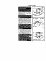
OPERATION
DUST
SAG
TRACKING
SCREW
Make sure power supply is 110-120 volts, 60 HZ, AC
only.
Before attempting to use your Sander, familiarize
yourself with all operating features (See Figure 1)
and
_ requirements.
ANDING
RELT_
FRONTIDLER
PU
Fig
SWITCH
The switch of your sander is equipped with a "lock
on" feature which is convenient when sanding for
extended periods of time. TO lock-on, simply depress
the trigger of the switch, push in the lock button
located on the side of the handle, then while holding
the lock button pushed in, release the trigger. See
Figure 2. To release the lock, depress the trigger and
release it. If you have the "Lock-On" feature engaged
during use and your Sander becomes disconnected
from power supply, disengage the "Lock-On" feature
LOCK "ON"
BUTTON
FRONT HANDLE
1
REAR HANDLE
Fig
2
PREPARING FOR OPERATION
For ease of operation and maintaining proper con.
troL your Sander has a front handle and a rear han.
die. These handles allow two-hand operation which
aid in maintaining
control, keeping sanding area
level with workpiece, and keeping hands clear of
sanding belt. When operating your Sander always
hold the front handle with your left hand anq the rear
handle with your right hand as shown in Fig. 2.
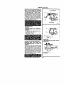
3.
KEEP HANDS AND FINGER:
Fig. 3
AWAY FROM THESE AREAS AT ALL TIMES
Always operate your Sander as shown in Fig. 2.
Page S
OPERATION
Selecting the correct size and type sanding bert is an
important step in achieving a high quagty Sanded
finish. Standard 3 Inch x 21 Inch sanding belts made
of aluminum oxide, silicone carbide, and other synthetic abrasives are best for power sanding. In
general, coarse grit will remove the most material
and fine grit will produce the smoothest finish in all
sanding operations. The condition of the surface to
be sanded wig determine which grit belt wIJI do the
job. If the surface is rough, start with a coarse grit
belt sanding until surface is uniform. Medium grit
belt may then be used to remove scratches left by
the coarser belt and fine grit belt used for finishing
of the surface. Always continue sanding with each
DUST BAG RETAINER
DUST
RAG
BLOWER COVER
Fig. 4
INSTALLING DUST BAG
See Figure 4.
DISCONNECT
SANDER FROM POWER SUPPLY
WHILE ASSEMBLING
PARTS OR MAKING ADJUSTMENTS.
TO INSTALL:
1. Fit opening in dust bag retainer over dust exhaust hole on blower cover.
2. Slide dust bag retainer in the direction of the arrow as shown in Figure 4.
3. Dust bag is secure when it fits snugly on blower
cover.
SANDING
BELT
i
INSTALLING
AND ADJUSTING
SANDING
BELT
DISCONNECT
SANDER FROM POWER SUPPLY
WHILE ASSEMBLING
PARTS OR MAKING AD.
JUSTMENTS.
TO release the sanding belt, Hft tension release lever
straight Up as shown in figure 6. When sufficient
force is exerted, the spring will be compressed
allowing the pulley to lock in a rear position. This
frees the sanding belt so it can be removed. Install
new belt making sure arrow inside of belt is pointing
in the direction of rotation, which is clockwise when
looking into open side of sander. See Fig. 5. Roughly
align the belt to its correct position, then release tension on pulley. Release tension by lowering tension
release lever as shown in Figure 6. The pulley will
snap back into operating position,
LOWER TENSION RELEASE LEVER TO SECURE
SANDING BELT
LIFT TENSION
RELEASE
SANDING
BELT
LEVER
TO
REMOVE
Fig 6
Page 6
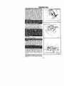
OPERATION
ALWAYS WEAR SAFETY GOGGLES OR SAFETY
GLASSES WITH SIDE SHIELDS WHEN OPERATING
YOUR SANDER. TO adjust Sahding belt, connect
Sander to power supply. Place Sander in upside
down position as shown in Figure 7. NOTE: This
position is for adjustments only. The Sander is not in
an operating position, Pull switch trigger and release
immediately, Observe tracking of sanding belt, If the
sanding belt runs inward, turn the tracking screw
clockwise. It the sanding belt runs Outward, turn the
tracking screw counterclockwise, This should be
done until you are sure belt will not run off sander, or
come in contact with internal parts. After installing a
new sanding belt, it may become necessary to
change the adjustment severa! times until the belt
becomes pliable,
SANDING
BELT
Fig 7
When you are sure the belt will not rub against inter.
nal pats start your Sander and fine adjust the tra_king screw unt I the be t stabilizes. See F gure 8
When co ec I_/adjusted
the outer edge of the belt
witlbeevenw_th
heou er edge of the base of your
Sande. Belt life will be greatly increased if a few
seconds are spent adjusting the belt tracking
TRACKING SCREW
\
TO OPERATE
Clamp or otherwise secure the work to prevent it
from moving under your Sander.
Fig.
8
Before placing Sander on work
ce,
squeeze the trigger switch and let the motor reach
s max mum speed then Ioweryour Sander to the
work surface w_th a slight forwardmotion, Usin=_!the
ear handle to controt your Sander and the front hand e bn y 1o gu de it, mcNe it s_wly over the work• See
Fig. 9, Allowing your Sander to remain in one place
will result in an uneven surface.
/
Your sander was designed to provide the proper
weight on the sanding belt. Extra pressure will result
in uneven work, clogged belts, and possibte motor
burnout. NOTE: The front ro_ler of your sander was
not designed for contour sanding• Sanding on the
front roller could cause irregularity in sanding belt
tracking•
Use a coarser belt when heavy cutting is desired, not
heavy pressure• The importance of this cannot be
over-emphaSized• The weight has been built into the
too{ to give the most efficient pressure at the proper
location.
r _ I_
_"
Fig 9
Page 7
MAINTENANCE
ir"lv_l-'l: I_11_
[e_l,&M
_I=1_It_l;I; LTItO]I _tqqlIkl =lh] _lll¢iel: fzl =IILILv,F_I_U
Ie]=l_|I [W_,IR _1=1
".II,_TN=lLvli=_i m'J=,l:| i_le pp_
=1_Ol
1
TIMING
BELT REPLACEMENT
D(SCONNECT
SANDER
BEFORE
SERVICING
WHEN
MENT
Number
1
2
3
4.
5
6
SMALL PULLEY
FROM
POWER
REPLACING
TIMING
BELT,
BELT
NUMBER
989368-000
5 on
Parts
List,
Page
SUPPLY
USE REPLACE.
ONLY.
See Key
11
Remove
sanding
belt from sander.
See installing
and
adiusting
sanding
belt,
Page
5. NOTE:
REMOVING
THE
SANDING
BELT
WILL
SIMPLIFY
THE
PROCESS
OF
INSTALLING
YOUR
NEW TIMING
BELT,
Remove
the two belt cover screws
Then remove
LARGE PULLEY
the belt cover
See Key Numbers
1 and 2 on exploded
view and parts
list, pages 10 and 11
Force
old
belt
from
small
pulley
with
a
screwdriver
and removeJt
fromlarge
pulley
If it
is worn out, simp{y cut the old belt and remove it.
IELT_VER
BELT
COVER SCREWS
Fig 10
APPLY PRESSURE
HERE AND TURN LARGE PULLEY
Install
new
belt
over
large
pulley
first.
See
Figure
10
Holding
ihe belt as shown
in Figure 11, press the
belt onto the smal_ pulley
NOTE: TO SIMPLIFY
THE PROCESS,
TURN THE LARGE
PULLEY
AS
YOU
PRESS
THE
BELT
ONTO
THE
SMALL
PULLEY.
Reass3mble
belt cover an0 screws
_r_r_'_NEVER
YOUR
SANDER
PLACE
ATTEMPT
TO OPERATE
WITHOUT
BELT
COVER
IN
SWITCH REPLACEMENT
DISCONNECT THE SANDER FROM POWER SUPPLY WHILE REPLACING PARTS OR MAKING ADJUSTMENTS.
1
Remove the handle cover and screws. NOTE THE
LOCATIONS OF ALL WIRING IN THE HANDLE
AND HOW EACH CONNECTION
IS MADE TO
THE SWITCH. Connections and wiring position
must be identical when installing
the new
switch See Figure 12
2 Lift the switch away from the handle, then release the
leads to the switch by inserting a 1/32 in. diameter pin or
nail into each switch lead receptacle. See Figure 13.
3
Make the lead connections to the new switch by
pushing each lead as far as possible into the
switch lead receptacles. Pull on leads to check
lead connections
with lead receptacles.
4,
Arrange the wiring in the handle so that it will not
be pinched or contact screws when the handle
cover and screws are replaced, then position the
switch in place. See Figure 12
5
Place the cord and bend relief
locations, See Figure 12.
6
Replace handle cover and screws,
7.
Tighten all screws securely.
in their
1/32 IN. DIAMETER
NAiL OR PIN
correct
Fig.
Page 8
t3
CORD REPLACEMENT
DISCONNECT THE SANDER FROM POWER SUPP.
LY WHILE REPLACING PARTS OR MAKING ADJUSTMENTS.
1 Ren_ove handle cover and screws as described
on Page 7. Note the locations of all wiring in the
handle and how each connection is made to the
cord. Connections and wiring position must be
identical when installing
the new cord
See
Figure 14.
2. Remove the switch from the handle and disconnect the cord leads from the switch. See Figure
15
3. Removethebendrelieffromoldcordandplaeeit
on the new one.
4 Push each lead of the new cord as far as possible
into the groper switch lead receptacles. Pug on
leads to check lead connections with lead reeeptacles
5. Arrange the wiring in the handle so that it will not
be pinched when handle cover and screws are
replaced.
Position
the switch in place See
Figure 14.
6. Place the bend relief and cord in their correct
locations, then replace handle cover and screws
? Tighten all screws securely,
SCREWS
1/32 IN. DIAMETER
NAIL OR PIN
Fig 15
GENERAL
Only the parts shown on parts list, page eleven, are
intended to be repaired or replaced by the customer.
All other parts represent an important part of the
double insulation system and should be serviced only by a qualified service technician.
Avoid using solvents when cleaning plastic parts
Most plastics are susceptible
to various types of
commercial solvents and may be damaged by their
use. Use clean ctoths to remove dirt, carbon dust,
etc.
When electric tools are used on fiberglass boats,
sports cars. etc., it has been found that they are sub
ject to accelerated wear and possible premature
failure, as the fiberglass
chips and grindings are
highly abrasive to bearings, brushes, commutator,
etc. Consequently
it is not recommended
that this
tool be used for extended work on any fiberglass
material During any use on fiberglass it is extremely
important that the tool is cleaned frequently by blow
ing with an air jet. ALWAYS WEAR SAFETY GOGGLES, SAFETY GLASSES WITH SIDE SHIELDS, OR
A DUST MASK DURING POWER TOOL OPERATION
OR WHEN BLOWING DUST.
LUBRICATION
All the bearings
in this
tool are lubricated
with
a sup
ficient
amount
of high grade lubricant
for the life of
the
unit
under
normal
operating
conditions,
therefore,
no further
lubrication
is required.
EXTENSION CORDS
The use of any extension cord wgl cause some loss
of power To keep the loss to a minimum and to prevent tool overheating, follow the recommended cord
sizes on the chart at right When tool is used ouP
doors, use only extension cords suitable for Outdoor
use and so marked Extension cords are available at
Sears Retail Stores.
Extension Cord Length
25-50 Ft
50-100 Ft
Page 9
Wire Size A,W.G.
16
14
CRAFTSMAN
3 INCH DUSTLESS BELT SANDER --
MODEL NUMBER 315.117151
2
SEE NOTE "A" PAGE 11
10
31
13
9
17
Page 10
CRAFTSMAN
3 INCH
DUSTLESS
BELT
SANDER
_
MODEL
NUMBER
315.117151
your Sander. Always mention the Model Number in all correspondence
, regarding your CRAFTSMAN SANDER or when ordering repair parts.
SEE BACK
PAGE
FOR
PARTS
ORDERING
INSTRUCTIONS
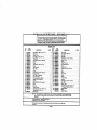
PARTS LIST
KEY
NO,
1
2
3
4
5
6
7
g
9
10
11
12
13
14
15
16
17
18
19
20
21
22
23
24
25
26
27
PART
NUMBER
610122-003
g88367.001
607776002
728693-020
ggg3gg-g00
998386-004
703493-809
998423.002
726693-004
98936_000
998372.001
999448-0O3
999937-001
998401-001
662167-012
008373.002
900004.002
999945-OO4
999927-001
622347-001
99gggg-001
900376.002
998370-001
998371-001
612665.0O5
*-*
998378.001
DESCRIPTION
"Screw (#8-32 x 3/8 In. Pan Hd, T.C,) ..........
Belt Cover ...............................
Driven Pulley ............................
• Screw (#8-32, x 3/8 in, FiL Hd,) ...............
Timing Serf ..............................
Gear Housing Cover w/Bearings ............
Washer .................................
Pinion ..................................
• Screw (#8-32 x 7/8 in, PiL Hd,) ...............
Pulley ..................................
Tracking Knob ...........................
Wear Strip ..............................
Blower .................................
* Screw (#10-32 x 3/8 In, Wafer Hd,) ...........
Retaining Ring ...........................
Idler Roller w/Bearings ...................
Idler Rofler Shaft .........................
Yoke Assembly with Spring ................
Release Lever Assembly ..................
Washer .................................
*Screw (#10-32 x 1/2 Jn.Pan Hd.) .............
Platen ..................................
Bushing ................................
Torsion Spdng ...........................
• Screw (#10-32 x 1/2 In. Pan Hd, T.F.) .........
Sanding Belt (3 In. x 21 in.) .................
Backing Pad ............................
NOTE:
,,A,. _ The assembly
shown teWssent$
allen or damage
to Ihe system
service
Retail $1o_.
"Slandatd
Hardwlre
Item _ May 6e purchased
• *Avail_bl e From DIv. 98 -- Sout¢ e 980.0G
KEY
NO,
QUAN.
PART
NUMBER
28 998380.001
29 999942-001
30 703774-003
31 ' 981548-o01
32 9895924)01
33 999931-001
34 998993.001
35 900300.001
36 998394-_
37 990493-006
38 999929-001
39 617006-009
41 998368-001
42 008895-001
43 613851-001
44 816247.001
45 931744-818
46 618103301
47 999347-001
48 989592-007
49 981547-O01
51 967878-0O3
52 812865-006
4
1
1
3
1
1
2
1
1
1
1
1
1
1
2
1
1
1
1
1
1
1
2
1
2
53
54
1
1
622347,603
622440-O00
612547-530
DESCRIPTION
Wear Plate ..............................
Drive Roller Assembly ....................
Steel Rail ...............................
Data Plate ...............................
• Screw (#8o10 x 1ol/8 In. Fit. Hd.) .............
Slower Cover ............................
Shroud .................................
Blower Housing ..........................
Oust Bag Assembly .......................
Cord ...................................
Handle Cover ............................
"Screw (8-10 x 5/8 in. Pan Hd._ ...............
Gear ...................................
Switch ..................................
Bend Relief .............................
Spring ..................................
Washer .................................
Thrust Washer ...........................
Deflector ...............................
*Screw (#8-10 x 2-1/4 fn. Fil. H.D.) ............
Logo Plate ..............................
Glamor Plate ............................
*Screw (#10-32 x 7/8 In. Pan Hd. T.F.)
For use with Key No. 51 only .............
Spdng Washer ...........................
Washer .................................
Owner's Manual
an Impor tanl pad of the Double Insulated
Syl;lem.
TO ivoid Ihe pol,ibili
W el ll_shoubd be performed
by your nearest
_ars
Rel_a_r Cenlen
Conta¢l
your
near_sl
Locally
• * *Sanding Belts In assorlld grll$ for bolh sandir_j wood ,rid melal rosy be obtained from your nea_Sl Sears
Retail Sto_.
Page
11
QUAN,
1
1
1
1
3
1
1
1
1
1
1
4
1
1
1
1
1
1
1
2
1
1
2
1
2
For repair of major brand appliances in your own home...
no matter who made it, no matter who sold it!
1-800-4-MY-HOME
sMA.ytir_edayor night
(1-800-469-4663)
,,_
www,sears.com
:
To bring in products such as vacuums, lawn equipment and electronics
!
for repair, call for the location of your nearest Sears Parts & Repair Center. :;
1-800-488-1222
Aoytir_e
dayor
night
www.sears.com
For the replacement parts, accessories and owner's manuals
that you need to do-it-yourself, call Sears PartsDirectS"!
1-800-366-PART
(1-800_366-7278)
_ am- 11p m CST,
11¸
7 days a week
www.sears.com/partsdirect
To purchase or inquire about a Sears Service Agreement:
1-800-827-6655
7 a.m, - 5 p.m. CST, Mon, - Sat,
Para pedir servicio de reparaci6n a domicilio,
y para ordenar piezas con entrega a domicilio:
1-888-SU-HOGAR_
Au Canadapourserviceenfrangais:
1-877-LE-FOYER s_
_;_ ,
(1-877-533-6937)
_,
(1 °888-784-6427)
® Registered Trademark _,= Trademark of SeBrs, _u¢_
¢_ Seats. RCebL, Ck aed CO
® Marca Reg_rada
and C_
/ _ Ma,ca de F#adca de Sears¸ Roebuck and CO