1
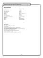
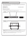
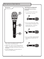
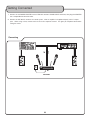
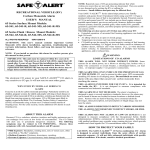
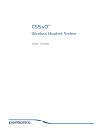
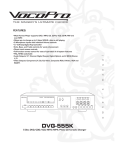
R
TM
DUAL CHANNEL VHF WIRELESS MICROPHONE SYSTEM
RF
VOLUME
VOLUME
CHANNEL 1
CHANNEL 2
o
w
n
e
r
POWER
RF
'
VHF-3000
s
m
a
n
u
a
l
THE SINGER'S ULTIMATE CHOICE
VHF-3000
DUAL-CHANNEL VHF WIRELESS MICROPHONE SYSTEM
Table of Contents
Safety instructions ............................................................ 2
FCC information ................................................................ 3
Welcome ......................................................................... 4
Listening for a lifetime ....................................................... 5
Specifications and features................................................. 6
Getting started ................................................................. 7
Front and rear panel descriptions........................................ 8
Microphone descriptions .................................................... 9
Getting connected........................................................... 10
Microphone basics .......................................................... 11
Operations ..................................................................... 12
Troubleshooting .............................................................. 13
R
TM
THE SINGERS ULTIMATE CHOICE
1
Safety Instructions
8. Ventilation - The appliance should be situated so its
location does not interfere with its proper ventilation. For
example, the appliance should not be situated on a bed,
sofa, rug, or similar surface that may block the
ventilation slots.
CAUTION
RISK OF SHOCK
CAUTION: To reduce the risk of electric shock,
do not remove cover (or back). No userserviceable parts inside. Only refer servicing to
qualified service personnel.
9. Heat - The appliance should be situated away from
heat sources such as radiators, heat registers,
stoves, or other appliances (including amplifiers)
that produce heat.
10. Power Sources - The appliance should be
connected to a power supply only of the type described
in the operating instructions or as marked on the
appliance.
Explanation of Graphical Symbols
The lightning flash & arrowhead
symbol, within an equilateral triangle,
is intended to alert you to the
presence of danger.
11. Grounding or Polarization - Precautions should be
taken so that the grounding or polarization means of
an appliance is not defeated.
12. Power-Cord Protection - Power-supply cords
should be routed so that they are not likely to be walked
on or pinched by items placed upon or against them,
paying particular attention to cords at plugs,
convenience receptacles, and the point where they exit
from the appliance.
The exclamation point within an
equilateral triangle is intended to alert
you to the presence of important
operating and servicing instructions.
WARNING
13. Cleaning - Unplug this unit from the wall outlet
before cleaning. Do not use liquid cleaners or
aerosol cleaners. Use a damp cloth for cleaning.
To reduce the risk of fire or electric shock, do
not expose this unit to rain or moisture.
14. Power lines - An outdoor antenna should be
located away from power lines.
1. Read Instructions - All the safety and operating
instructions should be read before the appliance is
operated.
15. Nonuse Periods - The power cord of the appliance
should be unplugged from the outlet when left unused
for a long period of time.
2. Retain Instructions - The safety and operating
instructions should be retained for future reference.
16. Object and Liquid Entry - Care should be taken so
that objects do not fall and liquids are not spilled into the
enclosure through openings.
3. Heed Warnings - All warnings on the appliance and in
the operating instructions should be adhered to.
17. Damage Requiring Service - The appliance should
be serviced by qualified service personnel when:
4. Follow Instructions - All operating and use
instructions should be followed.
A.
B.
C.
D.
The power supply cord or plug has been damaged; or
Objects have fallen into the appliance; or
The appliance has been exposed to rain; or
The appliance does not appear to operate normally
or exhibits a marked change in performance; or
E. The appliance has been dropped, or the enclosure
damaged.
5. Attachments - Do not use attachments not
recommended by the product manufacturer as they may
cause hazards.
6. Water and Moisture - Do not use this unit near water.
For example, near a bathtub or in a wet basement and
the like.
18. Servicing - The user should not attempt to service
the appliance beyond that described in the operating
instructions. All other servicing should be referred to
qualified service personnel.
7. Carts and Stands - The appliance should be used
only with a cart or stand that is recommended by the
manufacturer.
Note:
To CATV system installer's (U.S.A.): This reminder is
provided to call the CATV system installer's attention to
Article 820-40 of the NEC that provides guidelines for
proper grounding and, in particular, specifies that the
cable ground shall be connected as close to the point of
cable entry as practical.
7 A. An appliance and cart combination
should be moved with care. Quick stops,
excessive force, and uneven surfaces may
cause an overturn.
2
FCC INFORMATION (U.S.A.)
CAUTION:
READ THIS BEFORE OPERATING YOUR UNIT
1. IMPORTANT NOTICE: DO NOT MODIFY THIS
UNIT!: This product, when installed as indicated in the
instructions contained in this manual, meets FCC
requirements. Modifications not expressly approved by
Vocopro may void your authority, granted by the FCC,
to use this product.
1. To ensure the finest performance, please read this
manual carefully. Keep it in a safe place for future reference.
2. Install your unit in a cool, dry, clean place - away from
windows, heat sources, and too much vibration, dust,
moisture or cold. Avoid sources of hum (transformers, v
motors). To prevent fire or electrical shock, do not expose to
rain and water.
2. IMPORTANT: When connecting this product to
accessories and/or another product use only high
quality shielded cables. Cable(s) supplied with this
product MUST be used. Follow all installation
instructions. Failure to follow instructions could void your
FCC authorization to use this product in the U.S.A.
3. Do not operate the unit upside-down.
3. NOTE: This product has been tested and found to
comply with the requirements listed in FCC Regulations,
Part 15 for Class "B" digital devices. Compliance with
these requirements provides a reasonable level of
assurances that your use of this product in a residential
environment will not result in harmful interference with
other electronic devices. This equipment
generates/uses radio frequencies and, if not installed
and used according to the instructions found in the
owner's manual, may cause interference harmful to the
operation of other electronic devices. Compliance with
FCC regulations does not guarantee that interference
will not occur in all installations. If this product is found
to be the source of interference, which can be
determined by turning the unit "Off" and "On", please try
to eliminate the problem by using one of the following
measures:
4. Never open the cabinet. If a foreign object drops into the
set, contact your dealer.
Relocate either this product or the device that is being
affected by the interference.
9. This unit consumes a fair amount of power even when the
power switch is turned off. We recommend that you unplug
the power cord from the wall outlet if the unit is not going to
be used for a long time. This will save electricity and help
prevent fire hazards. To disconnect the cord, pull it out by
grasping the plug. Never pull the cord itself.
5. Place the unit in a location with adequate air circulation.
Do not interfere with its proper ventilation; this will cause the
internal temperature to rise and may result in a failure.
6. Do not use force on switches, knobs or cords. When
moving the unit, first turn the unit off. Then gently disconnect
the power plug and the cords connecting to other
equipment. Never pull the cord itself.
7. Do not attempt to clean the unit with chemical solvents:
this might damage the finish. Use a clean, dry cloth.
8. Be sure to read the "Troubleshooting" section on common
operating errors before concluding that your unit is faulty.
Use power outlets that are on different branch (circuit
breaker or fuse) circuits or install AC line filter(s).
In the case of radio or TV interference, relocate/reorient
the antenna. If the antenna lead-in is 300-ohm ribbon
lead, change the lead-in to coaxial type cable.
10. To prevent lightning damage, pull out the power cord
and remove the antenna cable during an electrical storm.
If these corrective measures do not produce satisfactory
results, please contact your local retailer authorized to
distribute Vocopro products. If you can not locate the
appropriate retailer, please contact Vocopro, 1728
Curtiss Court, La Verne, CA 91750.
11. The general digital signals may interfere with other
equipment such as tuners or receivers. Move the system
farther away from such equipment if interference is
observed.
NOTE:
Please check the copyright laws in your country
before recording from records, compact discs,
radio, etc. Recording of copyrighted material may
infringe copyright laws.
CAUTION
The apparatus is not disconnected from the AC power
source so long as it is connected to the wall outlet,
even if the apparatus itself is turned off. To fully insure
that the apparatus is indeed fully void if residual power,
leave unit disconnected from the AC outlet for at least
fifteen seconds.
Voltage Selector (General Model Only)
Be sure to position the voltage selector to match the
voltage of your local power lines before installing the
unit.
240V
120V
3
Welcome...
And Thank you for purchasing the VHF-3000 from VocoPro, your ultimate choice in
Karaoke entertainment! With years of experience in the music entertainment business,
VocoPro is a leading manufacturer of Karaoke equipment, and has been providing
patrons of bars, churches, schools, clubs and individual consumers the opportunity to
sound like a star with full-scale club models, in-home systems and mobile units. All our
products offer solid performance and sound reliability, and to reinforce our commitment
to customer satisfaction, we have customer service and technical support professionals
ready to assist you with your needs. We have provided some contact information for
you below.
VocoPro
1728 Curtiss Court
La Verne, CA 91750
Toll Free: 800-678-5348
TEL: 909-593-8893
FAX: 909-593-8890
VocoPro Company Email Directory
Customer Service & General Information
[email protected]
Tech Support
[email protected]
Remember Our Website
Be sure to visit the VocoPro website www.vocopro.com for the latest information on
new products, packages and promos. And while you're there don't forget to check out
our Club VocoPro for Karaoke news and events, chat rooms, club directories and even
a KJ Service directory!
We look forward to hearing you sound like a PRO, with VocoPro, your ultimate choice in
Karaoke entertainment.
FOR YOUR RECORDS
Please record the model number and serial number below, for easy reference, in case of loss or theft. These
numbers are located on the rear panel of the unit. Space is also provided for other relevant information
Model Number
Serial Number
Date of Purchase
Place of Purchase
4
Listening For A Lifetime
Selecting fine audio equipment such as the unit you’ve just purchased is only the start of
your musical enjoyment. Now it’s time to consider how you can maximize the fun and
excitement your equipment offers. VocoPro and the Electronic Industries Association’s
Consumer Electronics Group want you to get the most out of your equipment by playing it
at a safe level. One that lets the sound come through loud and clear without annoying
blaring or distortion and, most importantly, without affecting your sensitive hearing.
Sound can be deceiving. Over time your hearing “comfort level” adapts to a higher volume
of sound. So what sounds “normal” can actually be loud and harmful to your hearing. Guard
against this by setting your equipment at a safe level BEFORE your hearing adapts.
To establish a safe level:
• Start your volume control at a low setting.
• Slowly increase the sound until you can hear it comfortably and clearly, and without
distortion.
Once you have established a comfortable sound level:
• Set the dial and leave it there.
• Pay attention to the different levels in various recordings.
Taking a minute to do this now will help to prevent hearing damage or loss in the future.
After all, we want you listening for a lifetime.
Used wisely, your new sound equipment will provide a lifetime of fun and enjoyment. Since
hearing damage from loud noise is often undetectable until it is too late, this manufacturer
and the Electronic Industries Association’s Consumer Electronics Group recommend you
avoid prolonged exposure to excessive noise. This list of sound levels is included for your
protection.
Some common decibel ranges:
Level
Example
30
40
50
60
70
80
Quiet library, Soft whispers
Living room, Refrigerator, Bedroom away from traffic
Light traffic, Normal Conversation
Air Conditioner at 20 ft., Sewing machine
Vacuum cleaner, Hair dryer, Noisy Restaurant
Average city traffic, Garbage disposals, Alarm clock at 2 ft.
The following noises can be dangerous under constant exposure:
Level
Example
90
100
120
140
180
Subway, Motorcycle, Truck traffic, Lawn Mower
Garbage truck, Chainsaw, Pneumatics drill
Rock band concert in front of speakers
Gunshot blast, Jet plane
Rocket launching pad
-Information courtesy of the Deafness Research Foundation
5
Specifications and Features
SPECIFICATIONS
TX Frequency:
RF Output Power:
RF Spur Emission:
Normal Deviation:
Current Drain:
T.H.D.:
Sensitivity:
Mute Sen:
Audio Output Level:
Audio Frequency Responses:
S/N Ratio:
T.H.D.:
Battery:
Power:
170~260MHz
�10mW
-30dBC
±15KHz
�25mA
1%
15uV For 30dB S/N
-80dBm
0~300mV
100~10KHz±3dB
60dB
1%
9V Layers Style
AC110V or 220V
FEATURES
•
•
•
•
•
•
•
•
•
2 wireless handheld mics included
2 mic outputs
Individual Volume controls for precise vocal balancing
Dual antennas provide clear RF reception
VHF Band (180 MHZ-250MHZ) Quartz Lock for drift-free operation
Rugged 1 RU metal receiver chassis
Rack-mountable with included mounting brackets
Battery life: Approx: 12 hours
Receiver Dimensions: 10.25” (W) x 6.25” (D) x 2” (H)
6
Getting Started
Before starting any installation procedures, it is recommend that you completely unpack all the package contents.
The original packaging should be kept in the event that re-shipping is needed. Upon unpacking the VHF-3000, you
should have received the following items:
VHF-3000 receiver (1)
Handheld microphones (2)
Mounting brackets (1 pair)
AC power adapter (1)
3 ft. male/male ¼” cable (1)
9 volt alkaline batteries (2)
Mounting the VHF-3000
The included mounting brackets enable the VHF-3000 to be securley mounted into a 19” rackcase.
1. Attach mounting brackets to the VHF-3000 via the supplied mounting screws.
Brackets
1
2
4
Mounting
1
2
3
4
2. Align the VHF-3000 with the desired space in the rack and slowly slide in, rear panel first.
NOTE: Depending on your rack case design, it may be necessary to allow for sufficient space for the antennas.
3. While aligned, use rack case screws (not included) in the order shown below to stabilize the VHF-3000 in its
space, using the “X” rotation (numbered below) will ensure even tension and plush alignment.
NOTE: Do not tighten screws firmly until all screws are in place.
7
Front and Rear Panel Descriptions
Front Panel
2
1
VHF-3000
DUAL CHANNEL VHF WIRELESS MICROPHONE SYSTEM
RF
POWER
RF
VOLUME
VOLUME
CHANNEL 1
CHANNEL 2
4
3
1. POWER button - Turns the VHF-3000 On and Off.
2. VOLUME controls - Adjusts the individual VOLUME of the receiver’s 2 microphone channels.
3. POWER (LED) - Indicates whether the VHF-3000 is ON or OFF. When it is lit, the power is ON.
4. RF (LEDs) - Lights when RF signals are received from the microphone channels.
Rear Panel
7
6
VHF-3000
DUAL-CHANNEL VHF WIRELESS MICROPHONE SYSTEM
Professional Equipment no
user serviceable parts inside
!
www.vocopro.com
LA VERNE CALIFORNIA
U.
S.
A
ANT-B
RF B
RF A
SERIAL NO:
AC IN: 110V or 220V
CAUTION
RISK OF ELECTRICAL SHOCK
DO NOT OPEN
CAUTION: TO PREVENT ELECTRIC SHOCK,
DO NOT REMOVE COVER SCREWS
NO USER-SERVICEABLE PARTS INSIDE.
REFER SERVICING TO QUALIFIED
PERSONNEL
ANT-A
5
5. ANTENNAS - Provide the RF signal.
6. MIC CHANNEL OUTPUTS - These ¼” outputs are for connection to amplifiers, effects devices or mixers. OUT A
corresponds to CHANNEL 1 and OUT B corresponds to CHANNEL 2.
7. AC POWER connection - Main power jack for connection to an AC electrical outlet or power strip/surge
protector.
8
Microphone Descriptions
MAINTENANCE PROCEDURES
Microphone
Handheld Microphone Battery
Installation
1
1. To remove the cap, twist counterclockwise until it comes off.
2
2. Insert 1 fresh 9-Volt battery. Make
sure the battery is facing the correct
direction with the +/- end facing
towards the grill of the mic.
3
3. Close the BATTERY COMPARTMENT
lid by twisting it clockwise until it is
secure.
1. GRILL - Protects the microphone cartridge and helps
reduce “breathy” and wind noise pick-up.
2. POWER switch - Used to turn the microphone power ON
and OFF. The mic power is ON when the switch is in the
ON position and the power is OFF when the switch is in the
OFF position.
3. BATTERY COMPARTMENT - Removable lid hides and
protects the microphone battery.
9
Getting Connected
1. Connect the AC POWER ADAPTER to the VHF-3000 receiver’s POWER INPUT connector, then plug the ADAPTER
into a compatible AC electrical outlet.
2. Connect the VHF-3000’s receiver to a sound system, mixer or amplifier’s microphone input(s) with ¼” output
jacks. When using a mixer, connect each mic line into a separate channel. This gives you complete control when
mixing the vocals.
Connecting
DSP ECHO
V.CANCEL
V.PARTNER
VOCAL CANCEL/PARTNER
IN
VHF-3000
OUT
OUT
IN
DUAL CHANNEL VHF WIRELESS MICROPHONE SYSTEM
RF
POWER
RF
VOLUME
VOLUME
CHANNEL 1
CHANNEL 2
IN
VHF-3000
10
POWER
TAPE REC.
TAPE REC.
DSP
REVERB
LEVEL
SONIC
ENHANCER
LOW
HIGH
Microphone Basics
Microphone Position
The VHF-3000 is ideal for close-up vocals and can be held in the hand or mounted on a mic stand. The most
common applications and placement techniques are listed below. Keep in mind that microphone technique is largely a
matter of personal taste, and there is no one “correct” microphone position.
Proximity Effect
When the sound source is less than ¼” from the microphone, the microphone boosts bass frequencies (by 6 to 10
dB at 100 Hz), creating a warmer and richer bass sound than when farther away. This effect, known as proximity
effect, happens only in unidirectional dynamic microphones like the VHF-3000.
Feedback
Feedback occurs when the amplified sound from any loudspeaker reenters the sound system through any open
microphone and is repeatedly amplified. Most commonly, feedback is caused by the following conditions: placing
loudspeakers too close to microphones, having too many open active microphones, boosting tone controls
indiscriminately (mainly treble) and performing in areas with high ratios of room surfaces that have hard and reflective
surfaces such as glass, marble and wood. What to do if feedback occurs before the sound system is loud enough?
• Request that the talker speak louder into the microphone.
• Reduce the distance from the talker to the microphone. Each time this distance is halved, the sound system output
will increase by 6dB.
• Reduce the number of open microphones.
• Move the loudspeaker farther away from the microphone. Each time this distance is doubled, the sound system
output can be increased by 6dB.
• Move the loudspeaker closer to the listener.
• Use an equalizer/feedback reducer to cut the frequency bands in which the feedback occurs.
MICROPHONE PLACEMENT & TONE QUALITY
Lead & Backup Vocals
Lips should be less than 3” from or even touching the windscreen on an axis to the microphone. Doing this creates a
robust sound, emphasizes bass and provides maximum isolation from other sources.
Speech
When giving a speech or simply speaking, place the microphone 4” to 10” away from the mouth, just above nose
height for a natural sound with reduced bass. You can also place the microphone 8” to 16” away from the mouth,
slightly off to one side, for a more “distant” sound with highly reduced bass and minimal “s” sounds.
11
Operations
If you will be using the VHF-3000 with stage monitors and/or P.A. system, try the following:
•
•
in
•
Place the stage monitor directly behind the microphone.
Locate the P.A. loudspeakers so that they point away from the rear of the microphone. (With the speakers located
these positions, the possibility of feedback is greatly reduced).
Always check the stage setup before a performance to ensure optimum placement of microphone and monitors.
IMPORTANT: Every wireless microphone installation is a unique situation, and can present a variety of problems. Never
attempt a live performance without first conducting a “walkthrough” test of the system in the performing area. If major
changes (additional wireless systems or intercoms, relocation of scenery, etc.) have been made since the last walkthrough test, check the wireless system again, as close to performance time as possible.
P.A. S peakers F acing A wa y
Fr om R ear of M icr ophone
M onit or D irectl y B ehind
M icr ophone
OPERATIONS
1. Press the POWER button on the VHF-3000 receiver’s front panel. The power LED on the receiver will be BLUE.
2. Adjust the receiver’s VOLUME controls to approximately 50%.
3. Switch the microphone’s POWER BUTTONS to the ON positions.
4. Talk or sing into the microphones. During normal operation, the RF/AF signal LED’s will light RED when a
microphone is being used.
5. Adjust the receiver’s VOLUME controls until the output levels are balanced with eachother and other possible
source output i.e. CD+G tracks.
12
Troubleshooting
PROBLEMS
SOLUTIONS
No sound; receiver RF light(s) and mic(s) not lit.
Make sure POWER switches on transmitters and
receiver are set to ON positions.
Check microphone batteries to ensure they are
providing power.
Replace or charge batteries if necessary.
Check receiver's AC power connection.
Make sure antennas are in the microphones' line of
sight.
If necessary, reduce the distance between the
microphones and reciever.
No receiver sound but the RF lights are glowing.
Turn up the receiver's VOLUME level controls.
Check for proper connection between receiver and
external amplifier/mixer.
Talk into the mic and observe the receiver's RF signal
LEDs. If they glow, the problem is elsewhere in the
sound system.
Received signal is noisy or contains interference with
transmitter on.
Check microphone batteries and charge or replace if
power is low.
Remove local sources of RF interference, such as
lighting equipment. Two transmitters may be operating
at the same frequencies or frequencies which are too
close in proximity. Turn one off or exchange for one
with a different frequency. Signal may be too weak. If
so, reposition antenna (If possible, move them close to
the transmitter).
Noise coming from the receiver with the mics turned
OFF.
Remove local sources of RF interference, such as
lighting equipment.
Reposition the receiver or antennae.
Momentary loss of sound as transmitter is moved
around performing area.
Reposition receiver and perform a "walkthrough" test
and observe the signal strengths. If audio droppouts
persist, mark these "dead spots" in the performing
areas and avoid them during the performance.
Battery running low even after recharging.
Replace rechargeable batteries (rechargeable
batteries have a life of 500 hours of charging and
recharging).
13
�
��
����������������������������
VHF-3000 owner’s manual © VocoPro 2007
v2.0
www.vocopro.com