1
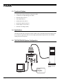
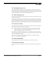
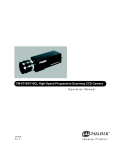
TM-7200 / TM-6200
High Resolution Digital CCD Camera
Operation Manual
69-0046
Rev. A
Notice
The material contained in this manual consists of information that is proprietary to PULNiX America, Inc., and may only
be used by the purchasers of the product. PULNiX America, Inc. makes no warranty for the use of its product and assumes
no responsibility for any errors which may appear or for damages resulting from the use of the information contained
herein. PULNiX America, Inc. reserves the right to make changes without notice.
Warranty
All of our solid state cameras have a full three year warranty. If any such product proves defective during this warranty
period, PULNiX America, Inc. will repair the defective product without charge for parts and labor or will provide a
replacement in exchange for the defective product. This warranty shall not apply to any damage, defect or failure caused
by improper use or inadequate maintenance and use.
Certifications
UL
CE
FCC: This equipment has been tested and found to comply with the limits for a Class A digital device, pursuant to Part 15
of the FCC Rules. These limits are designed to provide reasonable protection against harmful interference when the equipment is operated in a commercial environment. This equipment generates, uses and can radiate radio frequency energy
and, if not installed and used in accordance with the instruction manual, may cause harmful interference to radio communications. Operation of this equipment in a residential area is likely to cause harmful interference in which case the user
will be required to correct the interference at his own expense.
WARNING
Changes or modifications to this unit not expressly approved by the party responsible
for FCC compliance could void the user’s authority to operate the equipment.
TM-7200/TM-6200 Operation Manual
Printing: November 1998
PULNiX America, Inc.
1330 Orleans Drive
Sunnyvale, CA 94089
Tel: (408) 747-0300
Tel: (800) 445-5444
Fax: (408) 0880
E-mail: [email protected]
Web site: www.pulnix.com
Table of Contents
1 INTRODUCTION
1.1
1.2
1.3
1.4
1.5
Product Description .......................................................................... 1
Features ........................................................................................... 1
Functional Options ........................................................................... 2
Applications ...................................................................................... 2
TM-7200/TM-6200 System Configuration ........................................ 2
2 INSTALLATION
2.1
2.2
3.2
..................................................................... 3
Getting Started ................................................................................. 3
2.1.1 Unpacking Instructions ........................................................ 3
2.1.2 Components List ................................................................. 3
2.1.3 Accessories ......................................................................... 3
Camera Setup .................................................................................. 4
2.2.1 Rear Panel .......................................................................... 4
2.2.2 Connector Pin Configurations ............................................. 4
2.2.3 Power Supply and Power Cable Setup ................................ 5
2.2.4 Digital Cable Assembly ....................................................... 7
2.2.5 Attaching the Video Output ................................................. 8
2.2.6 Attaching the Camera Lens ................................................. 9
2.2.7 Back Focusing the Lens ...................................................... 9
2.2.8 Auto-Iris Lens Setup ............................................................ 9
2.2.9 Monitor Display Mode .......................................................... 9
2.2.10 Connectors and Cables ....................................................... 9
3 OPERATION
3.1
.................................................................... 1
.......................................................................... 10
Modes of Operation .......................................................................... 10
3.1.1 Shutter Operation ................................................................ 10
3.1.2 Asynchronous Reset with Shutter ....................................... 10
3.1.3 Integration ........................................................................... 14
3.1.4 Field Mode and Frame Mode .............................................. 14
3.1.5 Video Output ....................................................................... 15
3.1.6 Timing ................................................................................. 16
Adjustment Procedures .................................................................... 18
3.2.1 Signal Board ........................................................................ 18
3.2.2 Memory Board .................................................................... 19
3.2.3 Power Board ........................................................................ 20
4 TROUBLESHOOTING
4.1
4.2
........................................................... 21
Problems and Solutions ................................................................... 21
4.1.1 Symptom: No Video ............................................................. 21
4.1.2 Symptom: Dark Video .......................................................... 21
4.1.3 Symptom: Non-synchronized Video .................................... 21
Information and Support Resources ................................................ 22
i
Table of Contents
5 APPENDIX
5.1
5.2
5.3
.............................................................................23
Specifications ................................................................................... 23
5.1.1 Product Specifications ......................................................... 23
5.1.2 Physical Dimensions ............................................................ 24
5.1.3 Glass Specifications ............................................................ 25
5.1.4 C-Mount Specifications ........................................................ 25
5.1.5 Front End Detail ................................................................... 26
Spectral Response ........................................................................... 27
Block Diagram .................................................................................. 28
ii
List of Figures
FIGURE 1.
TM-7200/TM-6200 Rear Panel Configuration
FIGURE 2.
12P-02 Interface Cable (optional)
FIGURE 3.
External Pulse Width Mode
FIGURE 4.
Internal Fast Reset Mode
........................................................... 12
FIGURE 5.
Internal Slow Reset Mode
.......................................................... 13
FIGURE 6.
Async Reset Image Capture
FIGURE 7.
Integrated Image Capture Timing
FIGURE 8.
Continuous Sync Output
FIGURE 9.
Line Data Valid
FIGURE 10.
Frame Data Valid
FIGURE 11.
Pixel Clock
FIGURE 12.
Signal Board (top side)
FIGURE 13.
Memory Board (bottom side)
FIGURE 14.
Power Board
FIGURE 15.
Physical Dimensions
FIGURE 16.
Camera Front End - Glass Specifications
FIGURE 17.
Combination with “CS-Mount” Camera
FIGURE 18.
Front End Detail
FIGURE 19.
Front End Assembly
...................................................................27
FIGURE 20.
Spectral Response
.....................................................................27
FIGURE 21.
TM-7200/TM-6200 Block Diagram
iii
............................ 4
.............................................. 6
........................................................ 11
...................................................... 15
............................................... 15
............................................................ 16
...........................................................................16
........................................................................17
..................................................................................7
............................................................... 18
...................................................... 19
...............................................................................20
..................................................................24
.................................. 25
....................................... 25
.........................................................................26
............................................. 28
November 3, 1998
TM-7200/TM-6200
High Resolution
Digital CCD Camera
Operation Manual
1
INTRODUCTION
1.1 Product Description
The PULNiX TM-7200/TM-6200 CCD camera is a high resolution monochrome shutter camera with
asynchronous reset capability and a built-in video frame memory. The TM-7200/TM-6200 is designed
as a basic machine vision or automated inspection imaging sensor that provides low cost image capture
and storage functions right in the camera.
1.2 Features
•
High resolution 1/2" imager
TM-7200 (EIA): 768 (H) x 494 (V)
TM-6200 (CCIR): 752(H) x 582(V)
•
8-bit RS-422 digital output
•
Built-in asynchronous video memory
•
Asynchronous reset with external shutter control
•
Low light sensitivity (0.5 lux) with on-chip lenses
•
Eight shutter speeds to 1/31,000 sec. selectable via a convenient rotary selector switch
Page 1
INTRODUCTION
1.3 Functional Options
•
Frame mode setting for full frame integration (OP60)
•
Continuous sync output during reset (OP51)
•
Remoted imager (OP10-1)
•
AGC Enable (OP1-2)
•
Internal IR cut filter (OP3-1)
•
Optical Filter Removal (OP3-2)
•
Gamma Adjust to 0.45 (OP4-1)
•
Glassless CCD Imager (OP21)
1.4 Applications
The TM-7200/TM-6200 is designed as a basic machine vision or automated inspection imaging sensor.
It is excellent for applications such as on-line, high speed automated inspection, bar code and label
reading, and process inspection.
1.5 TM-7200/TM-6200 System Configuration
DIGITAL
POWER
SHUTTER
7 8
456
VIDEO
2 3
9 01
Computer with
Frame Grabber
Board
Power
Ext. Sync
Integration
Monitor
Page 2
TM-7200/TM-6200 High Resolution Digital CCD Camera
INSTALLATION
2
INSTALLATION
The following instructions are provided to help you to set up your video camera system quickly and
easily. It is suggested that you read through these instructions prior to unpacking and setting up your
camera system.
2.1 Getting Started
2.1.1 Unpacking Instructions
It is recommended that the original packing cartons for the cameras and lenses be saved in case there is
a need to return or exchange an item.
It is also recommended that any equipment being sent to another location for field installation be bench
tested to assure that everything is fully operational as a system.
2.1.2 Components List
Please begin by checking your order against the Components List (below) to assure that you have
received everything as ordered, and that nothing has been overlooked in the packing materials. If any
item is missing, please contact your PULNiX representative immediately.
•
TM-7200/TM-6200 (EIA) or TM-6200 (CCIR) camera
•
TM-7200/TM-6200 / TM-6200 Data sheet
•
PULNiX Camera Installation and Setup instructions
•
TM-7200/TM-6200 / TM-6200 Operation Manual
2.1.3 Accessories
Following is a list of additional accessories or equipment that may be recommended or required for your
particular application. Please check with your PULNiX representative prior to the installation of your
video system to determine what you might need.
•
Digital Cable: 30DG-02-7200
•
Power Cable: 12P-02
•
Power Supply: PD-12, DC-12N or K25-12V
•
B/W monitor
•
Lens
TM-7200/TM-6200 High Resolution Digital CCD Camera
Page 3
INSTALLATION
2.2 Camera Setup
2.2.1 Rear Panel
FIGURE 1.
TM-7200/TM-6200 Rear Panel Configuration
• 12-pin connector (power)
• 31-pin connector (digital output)
DIGITAL
• Video connector
POWER
SHUTTER
7 8
2 3
9 01
• Shutter control switch
456
VIDEO
2.2.2 Connector Pin Configurations
2.2.2 (a)
12-Pin Connector
1
The TM-7200/TM-6200 has a 12-pin connector for power
input.
Page 4
Pin#
Description
Pin#
Description
1
GND
7
VD Input
2
+12V DC
8
GND
3
GND
9
HD Input
4
Video Out
10
GND
5
GND
11
INT. CONT.
6
VINIT
12
GND
2
3
9
11
4
8
10
7
12
5
6
TM-7200/TM-6200 High Resolution Digital CCD Camera
INSTALLATION
2.2.2 (b)
31-Pin Connector
16
1
The TM-7200/TM-6200 has a 31-pin connector for digital output.
Pin#
Description
I/O
Pin#
Description
I/O
1
CLK+
O
17
CLK-
O
2
LDV+
O
18
LDV-
O
3
FDV+
O
19
FDV-
O
4
GND
20
VINIT
I
5
FI+
O
21
FI-
O
6
INTEG
I
22
ENINT
I
7
LPULSE
O
23
GND
8
D0+
O
24
D0-
O
9
D1+
O
25
D1-
O
10
D2+
O
26
D2-
O
11
D3+
O
27
D3-
O
12
D4+
O
28
D4-
O
13
D5+
O
29
D5-
O
14
D6+
O
30
D6-
O
15
D7+
O
31
D7-
O
16
GND
31
17
2.2.3 Power Supply and Power Cable Setup
2.2.3 (a)
Power Supplies
PULNiX recommends the following power supplies:
K25-12
110V AC/12V DC
2.1A power supply
P-15-12
220V AC/12V DC
2.1A power supply
K50-12
110V AC/12V DC
4.2A power supply
PD-12P
110V AC/12V DC
0.5A power supply
For users providing power through the 12-pin connector, the PD-12P power supply is available with the
12-pin mating connector already attached to the leads from the power supply. The PD-12 power supply
can be connected to the PULNiX power cable via a terminal strip or directly.
When wiring the PD-12 power supply directly, please note the following:
•
Twist the lead ends together and tin solder for strength and electrical continuity.
•
Use shrink tubing or a similar insulator to prevent exposed leads from touching.
•
The +12V lead is marked with a red stripe or white lettering; be sure not to reverse the leads.
•
Properly insulate all connections to prevent shorting.
TM-7200/TM-6200 High Resolution Digital CCD Camera
Page 5
INSTALLATION
2.2.3 (b)
PULNiX Power Cables
If you are using PULNiX power cables, such as the 12P-02, KC-10, etc., please refer to the pin-out
diagram. The color coded leads use Grey for Ground and Yellow for +12V DC.
FIGURE 2.
12P-02 Interface Cable (optional)
Flying
Leads
32mm
1
2,000mm± 10mm
(2 Meters)
1 PC-12P (Hirose Part #10A-10P-12S/PC12P)
12P-02 Interface Cable
Note:
Pin#
Lead Color
Function
Pin#
Lead Color
Function
1
Gray
GND
7
Black coax
VD Input
2
Yellow
+12VCD
8
White coax shield
GND
3
Red coax shield
GND
9
White coax
HD Input
4
Red coax
Video
10
Brown
GND
5
Orange coax shield
GND
11
Blue
Int. Cont.
6
Orange coax
VINIT
12
Black coax shield
GND
Make sure that the unused leads are not touching and that there is no possibility that the
leads could short due to exposed wires.
2.2.3 (c)
“K” Series Power Supplies
Attach the 110V line cord to the two terminals marked “AC”. Do not plug the cord into a 110V AC
socket until later in the procedure. Next, attach the Grey and Yellow leads of the power cable to the
Ground and 12V DC terminals respectively. Be sure to replace the plastic terminal guard on the power
supply at this time.
Note:
The “K” series power supplies are designed primarily for OEM users who will be
mounting the power supply inside a protective enclosure. For use in exposed situations,
the DC-12N and PD-12 are recommended.
2.2.3 (d)
Building Your Own Power Cable
Consult the pin-out for the camera purchased. Connect the Ground and +12V power leads of the PC12P power connector to Pin #1 and Pin #2, respectively (power must be DC regulated and of sufficient
current to properly power the camera).
Page 6
TM-7200/TM-6200 High Resolution Digital CCD Camera
INSTALLATION
2.2.3 (e)
Attaching the Power Cable to the Connector
The 12-pin connector is keyed and will only fit in one orientation. Rotate the connector while applying
slight pressure until the keyways line up. Press the connector into place until firmly seated.
The power cord may now be plugged into the 100V AC socket and the camera powered up.
2.2.4 Digital Cable Assembly
2.2.4 (a)
31-Pin Connector (MP211-031-113-4300)
1
16
31
17
Pin#
Signal
Cable
Pin#
Signal
Cable
1
CLK+
OR 1 RED
17
CLK-
OR 1 BLUE
2
LDV+
GRY 1 RED
18
LDV-
GRY 1 BLUE
3
FDV+
WHT 1 RED
19
FDV-
WHT 1 BLUE
4
GND
YLW 1 RED
20
VINIT
YLW 1 BLUE
5
FI+
PINK 1 RED
21
FI-
PINK 1 BLUE
6
INTEG
OR 2 RED
22
EN INTEG
OR 2 BLUE
7
L PULSE
WHT 2 RED
23
GND
GRY 2 BLUE
8
D0+
WHT 2 RED
24
D0-
WHT 2 BLUE
9
D1+
YLW 2 RED
25
D1-
YLW 2 BLUE
10
D2+
PINK 2 RED
26
D2-
PINK 2 BLUE
11
D3+
OR 3 RED
27
D3-
OR 3 BLUE
12
D4+
GRY 3 RED
28
D4-
GRY 3 BLUE
13
D5+
WHT 3 RED
29
D5-
WHT 3 BLUE
14
D6+
YLW 3 RED
30
D6-
YLW 3 BLUE
15
D7+
PINK 3 RED
31
D7-
PINK 3 BLUE
16
N/C
TM-7200/TM-6200 High Resolution Digital CCD Camera
Page 7
INSTALLATION
2.2.4 (b)
37-Pin D-Sub Connector
19
1
37
20
Pin#
Signal
Cable
Pin#
Signal
Cable
1
CLK+
OR 1 RED
20
CLK-
OR 1 BLUE
2
LDV+
GRY 1 RED
21
LDV-
GRY 1 BLUE
3
FDV+
WHT 1 RED
22
FDV-
WHT 1 BLUE
4
N/C
23
GND
GRY 2 BLUE
5
FI+
24
FI-
PINK 1 BLUE
PNK 1 RED
6
N/C
25
N/C
7
N/C
26
N/C
8
D0+
WHT 2 RED
27
D0-
WHT 2 BLUE
9
D1+
YLW 2 RED
28
D1-
YLW 2 BLUE
10
D2+
PINK 2 RED
29
D2-
PINK 2 BLUE
11
D3+
OR 3 RED
30
D3-
OR 3 BLUE
12
D4+
GRY 3 RED
31
D4-
GRY 3 BLUE
13
D5+
WHT 3 RED
32
D5-
WHT 3 BLUE
14
D6+
YLW 3 RED
33
D6-
YLW 3 BLUE
15
D7+
PINK 3 RED
34
D7-
PINK 3 BLUE
16
GND
YLW 1 RED
35
GND
SHIELD
17
VINIT
YLW 1 BLUE
36
N/C
18
EN INTEG
OR 2 BLUE
37
INTEG
19
N/C
OR 2 RED
2.2.5 Attaching the Video Output
Most users utilize the BNC connector for video output from the camera. Connect the output from the
camera to the input of your monitor, VCR or switching device. The input of the monitor should be
balanced for 75Ω termination. Standard RG-59 type coaxial cable should carry a full video signal for up
to 500 feet.
Users wishing to output the video and input the power and sync to a camera over a single cable can use
the PULNiX multi-conductor cables, such as the 12P-02, the KC-10, etc. The mini coaxial leads in
PULNiX multi-conductor cables are designed for short runs of no longer than 100 feet.
Note: Make sure that no extraneous wires are visible which could cause a short.
Page 8
TM-7200/TM-6200 High Resolution Digital CCD Camera
INSTALLATION
2.2.6 Attaching the Camera Lens
The TM-7200/TM-6200 camera accepts 1/2" or larger format size C-mount lenses. To attach the Cmount lens to the camera, carefully engage the threads and rotate the lens clockwise until it firmly seats
on the mounting ring. Do not force the lens if it does not seat properly. Please note that some lenses with
extremely long flangebacks may exceed the mounting depth of the camera.
2.2.7 Back Focusing the Lens
To backfocus the TM-7200/TM-6200 camera, first attach a C-mount lens in the lens mount. Be sure that
the lens is properly mounted.
Set the lens focus to infinity (if the lens is a manual iris, set the iris to a high f-stop while still retaining a
well-illuminated image). Obtain the best focus possible at this setting, then loosen the two miniature hex
head set screws locking the focus ring in place. Now turn the entire lens and focus ring assembly back
and forth until the best image is obtained. Tighten the focus ring set screws. Your backfocus is now set.
2.2.8 Auto-Iris Lens Setup
Auto-iris lenses with full video input can be used with the PULNiX TM-7200/TM-6200, although this
camera model does not come equipped with auto-iris output.
Note:
Make sure that the power is removed from the camera before connecting or disconnecting
the auto-iris lens. There is a small chance that damage could occur to the auto-iris lens by
plugging or unplugging it while the camera is powered up.
Power down the camera before installing the auto-iris lens. To install the auto-iris lens in a PULNiX
camera for which the auto-iris input is not supplied, wire the signal (video) on the lens into the terminal
1 Vp to peak video output on the camera.
Point the camera at a light area and then quickly towards a darker area. If everything is working
properly, the iris should adjust for the light change.
2.2.9 Monitor Display Mode
For monitoring real time video, connect the video output to a video monitor or other device.
2.2.10 Connectors and Cables
12-pin connector and cable: Standard cable is 12P-02 (2m, 8 conductor cable) for power and external
controls.
TM-7200/TM-6200 High Resolution Digital CCD Camera
Page 9
OPERATION
3
OPERATION
3.1 Modes of Operation
3.1.1 Shutter Operation
The TM-7200/TM-6200 has a substrate drain type shutter mechanism which provides a superb picture
at various speeds without smearing. Manual shutter speed control can be selected at 1/60, 1/125, 1/250,
1/500, 1/1000, 1/2000, 1/4000, or 1/10,000 sec. rate.
3.1.2 Asynchronous Reset with Shutter
The TM-7200/TM-6200's asynchronous reset is flexible and takes external HD for phase locking.
Applying a VINIT pulse resets the camera's scanning and purging of the CCD.
TABLE 1.
Shutter Control
Manual Mode
Page 10
4 56
78
9 01
2 3
When async reset pulse (VINIT) is applied to High state (+5V) with dial
switch select from1 to 9, the TM-7200/TM-6200 asynchronous camera
discharges the photo charges into the substrate drain although the camera is
still running on its sync timing and only outputs captured video. When the
negative going reset pulse is applied, the camera will latch the falling edge
to its next horizontal drive and reset vertical sync timing immediately. Then
it starts integrating for the period of shutter control set by either an external Shutter Control Switch
pulse width pulse or internal shutter control. Therefore the horizontal phase
will not be interrupted. The TM-7200/TM-6200 asynchronous camera will output one field of shuttered
video after reset.
Async Reset Mode
Set
TM-7200/TM-6200
TM-7200
TM-6200
0
1/60
normal 1/60
normal 1/50
1
1/125
0.5H 1/31,000
1/31,000
2
1/250
1.5H 1/10,000
1/10,000
3
1/500
3.5H 1/4,500
1/4,500
4
1/1,000
6.5H 1/2,400
1/2,400
5
1/2,000
16.5H 1/950
1/950
6
1/4,000
32.5H 1/480
1/480
7
1/10,000
64.5H 1/245
1/245
8
N/C
128.5H 1/120
1/120
9
N/C
Shutter determined by pulse width
TM-7200/TM-6200 High Resolution Digital CCD Camera
OPERATION
There are three modes to control the asynchronous reset and shutter speed, External Pulse Width Mode,
Internal Fast Reset Mode and Internal Slow Reset Mode.
3.1.2 (a)
External Pulse Width Mode
The TM-7200/TM-6200 can be reset with external reset pulse (VINIT). Set the dial switch to “9”.
Apply a pulse width control VINIT signal generated from an external event trigger to the camera The
internal reset pulse will be latched to HD and at 9th HD timing from the external pulse leading edge
(negative going edge). The CCD discharge pulse will be generated to clear the images. The internal
VINIT will be generated at the following edge (positive going edge) of the external pulse, resetting the
internal timing including the video sync. The shutter speed is the same as the external pulse width, but
the integration delays 9H from the leading edge.
FIGURE 3.
External Pulse Width Mode
External
Pulse
Width
(Vinit)
X
Hd
Internal Vinit
9.5H
Transfer Gate
Pulse
10H
X
Exposure Time
Discharge
Pulse
Composite
Video
For the progressive format, one frame of video output will start from the rising edge of the pulse width
control. The camera will output the same video from memory when VINIT is kept high (5V), then
update the image upon receiving the next pulse. At async mode with external pulse input high, the video
output will be disabled as the camera continues discharging the CCD image providing black video only.
This feature is especially important in capturing moving objects at the precise location of the field of
view, such as belt conveyer, fast event observation and still image capturing.
TM-7200/TM-6200 High Resolution Digital CCD Camera
Page 11
OPERATION
3.1.2 (b)
Internal Fast Reset Mode
The video signal has no delay from the reset timing. Shutter speed range is 1/2400 to 1/31,000 sec.
Select a dial switch setting from "1" to "4". When the fast reset mode is selected, the camera resets with
internal VINIT timing, which is latched to Hd, and video output is also synchronized with internal
VINIT timing without further delay. The shutter speed is controlled by the dial switch on the camera’s
rear panel.
FIGURE 4.
Internal Fast Reset Mode
External
Pulse
Hd
Internal Vinit
9.5H
Transfer Gate
Pulse
Exposure Time
Purge Pulse
(discharge)
Composite
Video
Page 12
TM-7200/TM-6200 High Resolution Digital CCD Camera
OPERATION
3.1.2 (c)
Internal Slow Reset Mode
The speed control ranges from 1/120 to 1/950 sec. The video signal starts with internal V. Select a dial
switch setting from "1" to "4". With the internal slow reset mode selected, the camera operates the reset
and shutter in the same way as the external double pulse control mode. When the external VINIT pulse
is applied, internal VINIT is latched to Hd and the second internal VINIT signal is delayed to set up the
shutter speed period. The shutter speed is controlled by the dial switch from "5" to "8". Video output
timing starts right after the second internal VINIT.
FIGURE 5.
Internal Slow Reset Mode
External
Pulse
Hd
Internal Vinit
X
9.5H
Transfer Gate
Pulse
Purge Pulse
10H
(Discharge)
Exposure Time
Composite
Video
TM-7200/TM-6200 High Resolution Digital CCD Camera
Page 13
OPERATION
3.1.3 Integration
The CCD imager of the TM-7200/TM-6200 can be exposed longer than normal TV timing (16.7 msec.).
Because the TM-7200/TM-6200 has an interline transfer chip, a full frame of resolution is achievable
with the Frame Mode option (OP60).This feature provides high sensitivity for dark environment
applications.
Note:
A full frame is not available in the shutter mode.
Integration is achieved by controlling pin #11 of the 12-pin connector to Low (GND). Integration also
can be controlled by VINIT with the pulse width more than one field.
During integration, the signal processing keeps optical black levels as the reference black video to
clamp video levels. This results in cancelling out thermal noise during the integration period.
3.1.4 Field Mode and Frame Mode
The standard factory setting for the TM-7200/TM-6200 cameras is FIELD MODE. The mode selection
is by solder jumper on the process board and should only be changed by a PULNiX factory authorized
representative. If FRAME MODE is required, please contact PULNiX for this setting. The differences
between the two modes is explained below.
3.1.4 (a)
Field Mode
In Field Mode, two horizontal rows are scanned together, changing the pair at each interlace scan
(Fig. ). The sensitivity of the CCD is doubled for one field of integration, therefore it can obtain the
same sensitivity as in Frame Mode in half the period of time. This is an advantage when the shutter is
used often. Because of the alternating two row scanning, Moire is almost unnoticeable. While the
vertical resolution is not as good as in Frame Mode, it is sufficient to view the full vertical resolution of
the TV format.
Note:
Field Mode cannot provide full frame resolution with strobe lighting applications.
3.1.4 (b)
Frame Mode
In Frame Mode, each horizontal row is scanned as interlace scanning. The integration of each pixel is
one frame period. Vertical pixel resolution is good, and exact location is obtained. A disadvantage as
compared with Field Mode is the tendency to show vertical Moire. For strobe lighting, Frame Mode
must be used to achieve full frame resolution.
Page 14
TM-7200/TM-6200 High Resolution Digital CCD Camera
OPERATION
3.1.5 Video Output
3.1.5 (a)
Async Reset Image Capture
With built-in memory, an image can be captured when VINIT pulse is applied. The captured image will
be continuously scanned out until the next VINIT pulse occurs.
FIGURE 6.
Async Reset Image Capture
VINIT
VD
CAPTURED VIDEO
NORMAL VIDEO
VIDEO
REPEATED FIELD
3.1.5 (b)
Built-in Memory for Integration Image Capture
With EN INT high (enable integration, pin #10), set the integration control (pin #11) to low for
integration. Integrated video can be captured once integration control goes back to high. All captured
fields in this case are the same fields.
With the full frame integration option, the TM-7200/TM-6200 provides one full frame (two fields) of
integrated image. This option requires additional frame memory inside the camera.
FIGURE 7.
Integrated Image Capture Timing
EN INT
INT CONT
INTEGRATED
CAPTURED VIDEO
CAPTURED INTEGRATED VIDEO
VIDEO
NORMAL
VIDEO
VIDEO
REPEATED FIELD
TM-7200/TM-6200 High Resolution Digital CCD Camera
REPEATED FIELD
REPEATED FIELD
Page 15
OPERATION
3.1.5 (c)
Continuous Sync Output Option (OP51) )
When async reset is applied, video sync is also reset asynchronously. This phenomenon causes video
picture rolling or bouncing on the monitor. With this option, a continuous output (no more bouncing or
rolling pictures) will be achieved at async reset.
FIGURE 8.
Continuous Sync Output
ASYNC RESET
A
B
ASYNC VIDEO OUTPUT
STANDARD
A
B
A
B
CONTINUOUS OUTPUT
A: PREVIOUSLY GRABBED IMAGE
B
B: NEW CAPTURED IMAGE
3.1.6 Timing
3.1.6 (a)
Digital Video
Differential line-driven, 10-bit parallel signal with EIA-422 format. 100Ω output termination
impedance. Output from 31-pin connector. Mating connector: Airborne MP211-031-113-4300. Please
consult digital cable information, e.g., 50-13-1-01, 30DG-02 (8-bit) or 30DG-02-10 (10-bit), 2m cable.
3.1.6 (b)
Line Data Valid
This is differential line-driven signal with EIA-422 format. It is active high (+ side is higher than - side)
during the transfer of each line of data, producting horizontal line readout.
FIGURE 9.
Line Data Valid
HD
63.5µSec.
LDV
2µSec.
Page 16
TM-7200/TM-6200 High Resolution Digital CCD Camera
OPERATION
3.1.6 (c)
Frame Data Valid and Odd/Even Field Valid
This is differential line-driven signal with EIA-422 format. It is active high during the transfer of each
frame data. During integration, both LDV (Line Data Valid) and FDV (Frame Data Valid) are kept low
and restart upon the completion of integration. When F1 is kept high, the camera outputs odd field data;
otherwise, even field data is output.
FIGURE 10.
Frame Data Valid
VD
9H
VIDEO OUT.
4H
1H
OB
NON-INTERLACE
FDV (DIGITAL)
16.4ms
FDV
1H
FI
3.1.6 (d)
Pixel Clock
Differential line-driven signal with EIA-422 format. The frequency is 40.068 MHz (standard).
FIGURE 11.
Pixel Clock
DIGITAL DATA
N-5
N-4
N-3
N-2
PIXEL CLOCK
4nsec
69.9nsec.
TM-7200/TM-6200 High Resolution Digital CCD Camera
Page 17
OPERATION
3.2 Adjustment Procedures
3.2.1 Signal Board
FIGURE 12.
Signal Board (top side)
W1
AGC
MGC
VR1
VR2
VR3
VR4
W2
U1
OFF
ON
W3
AV
DV
U3
W4
R
S
U2
J4
Page 18
Set
Set
Set
Set
Set
Set
Set
W1(AGC/MGC)
W2(GAMMA)
W3(DV/AV)
W4(Video R/S)
W5(N/P)
W6(FRM/FLD)
W7(SMD2)
VR1
VR2
VR3
VR4
AGC
MGC
AGC MAX
Pedestal
Right (MGC) Manual Gain
Left(1) Gamma = 1.0
Left(DV) Direct analog (right)
Left(R)
Open(N)
Open(FLD)
Open
TM-7200/TM-6200 High Resolution Digital CCD Camera
OPERATION
3.2.2 Memory Board
FIGURE 13.
Memory Board (bottom side)
VR2
VR1
W3
C
R
U10
W2
W1
C
R
C
R
U5
U9
P
U8
W4
N
W7
W8
FM
FL
1
2
J3
Set
Set
Set
Set
Set
Set
W1(FLD)
W2(HD)
W3(VD)
W4(P/N)
W7(MFM1/2)
W8(FM/FL)
Left(R)
Left(R)
Left(R)
Open(N)
Open(2)
Open(FL)
VR1 A/D VREF
VR2 D/A VREF
TM-7200/TM-6200 High Resolution Digital CCD Camera
Page 19
OPERATION
3.2.3 Power Board
FIGURE 14.
Power Board
VR2
VR1
J3
VR1 EXT. VD PHASE
VR2 PLL
Page 20
TM-7200/TM-6200 High Resolution Digital CCD Camera
TROUBLESHOOTING
4
TROUBLESHOOTING
4.1 Problems and Solutions
Following are troubleshooting tips for common problems. Generally, problems can easily be solved by
following these instructions. If the following remedies fail to offer a solution to your problems, please
contact a PULNiX representative.
4.1.1 Symptom: No Video
Remedies: Check that the following are properly connected and operational.
•
Power supplies
•
Power cables
•
Main power source
•
Shutter control
•
Async mode
•
Lens
4.1.2 Symptom: Dark Video
Remedies: Check that the following are properly connected and operational.
•
Shutter selection
•
Iris opening on the lens
4.1.3 Symptom: Non-synchronized Video
Remedies: Check that the following are properly connected and operational.
•
Proper mode output
•
Frame grabber software camera selection
TM-7200/TM-6200 High Resolution Digital CCD Camera
Page 21
TROUBLESHOOTING
4.2 Information and Support Resources
For further information and support:
Phone:
408-747-0300
800-445-5444
800-3-PULNIX (24-hour message access)
Page 22
Fax:
408-747-0660
E-mail:
[email protected]
Mail:
PULNiX America Inc.
Sales Department
1330 Orleans Drive
Sunnyvale, CA 94089
ATTN: Video Applications
Web Site:
www.pulnix.com
TM-7200/TM-6200 High Resolution Digital CCD Camera
APPENDIX
5
APPENDIX
5.1 Specifications
5.1.1 Product Specifications
Model
Imager
Pixels
Cell size
Sensing area
TM-7200 (EIA)
TM-6200 (CCIR)
1/2 inch interline transfer CCD
768 (H) x 494 (V)
752 (H) x 582 (V)
8.4 (H) x 9.8 (V) microns
8.4 (H) x 8.2 (V) microns
6.41 (H) x 4.89 (V) mm
Dynamic range
Chip size
Scanning
67dB
7.95 mm (H) x 6.45 mm (V)
525 lines, 2:1 interlace
625 lines, 2:1 interlace
Clock
28.6363 MHz
28.3750 MHz
Pixel clock
14.31818 MHz
14.18750 MHz
15.734 KHz
15.725 KHz
59.94 Hz
50.00 Hz
570(H) x 485(V) lines
560(H) x 575(V) lines
Horizontal frequency
Vertical frequency
TV resolution
Video output
Analog: 1.0V p-p composite video, 75Ω
Digital: 8-bits RS-422 differential output,
Data clock
14.3MHz
S/N ratio:
50 dB min.
Min. illumination
AGC
Gamma
Lens mount
0.5 lux (F=1.4) without IR cut filter
ON/OFF (OFF std.)
1.0 std. (0.45 optional)
C-mount
Power requirement
DC 12V, 300 mA
Operating temperature
-10 °C to +50 °C
Storage temperature
30 °C to +60 °C
Operating humidity
Max. 70%
Storage humidity
Max. 90%
Vibration & Shock
Dimensions:
Weight:
TM-7200/TM-6200 High Resolution Digital CCD Camera
7 G (11 Hz to 200 Hz), 70 G
42mm x 32mm x 130mm
206 grams (6.65 oz.)
Page 23
APPENDIX
5.1.2 Physical Dimensions
FIGURE 15.
Physical Dimensions
118 mm (Remote)
"C" mount
PULNiX
32 mm
130 mm
42 mm
142.7mm
M2 (4X)
PULNiX
LAPP
PG 7
25 mm SQUARE
PATTERN
47 mm
25.4 mm
1/4-20 UNC-2B
44.8 mm
1/4-20 UNC-2B
8 mm
REMOTE HEAD
Page 24
TM-7200/TM-6200 High Resolution Digital CCD Camera
APPENDIX
5.1.3 Glass Specifications
FIGURE 16.
Camera Front End - Glass Specifications
CCD Glass (BK-7) 0.75mm thickness
Refractive Index = 1.5
Glass Cover (BD-65) 1.0mm thickness
Refractive Index = 1.51
CCD
Glass Cover
CCD Glass
5.1.4 C-Mount Specifications
The Flange Back Length of the CS-Mount is 12.5mm versus 17.526 of the C-Mount. The shorter Flange
Back Length of the “CS-Mount” allows room for the stripe filter incorporated in the color camera.
Additionally, the shorter Flange Back Length allows for reduction of the effective diameter of the first
lens and reduces the number of lens elements. The common C-Mount lens is completely compatible
with a CS-Mount camera when a 5mm extension ring is inserted between the lens and the camera.
FIGURE 17.
Combination with “CS-Mount” Camera
CS-Mount Lens
Focal Point
5mm Extension Ring
C-Mount Lens
5
12.5
17.526
Flange Surface of
C-Mount
TM-7200/TM-6200 High Resolution Digital CCD Camera
Page 25
APPENDIX
5.1.5 Front End Detail
FIGURE 18.
Front End Detail
18.20
Front End
1.00
Image Plane
C-Mount Ring
CCD Imager
1.41
Page 26
16.8
TM-7200/TM-6200 High Resolution Digital CCD Camera
APPENDIX
FIGURE 19.
Front End Assembly
C-MOUNT
RING
FILTER
GASKET
PIN 1
I.C.
FRONT
END
2X MOUNTING
HARDWARE
3X C-MOUNT RING
LOCKING SET SCREW
5.2 Spectral Response
FIGURE 20.
Spectral Response
1.0
O.9
0.8
0.7
Relative Sensitivity
0.6
0.5
0.4
0.3
0.2
0.1
0
400
500
600
TM-7200/TM-6200 High Resolution Digital CCD Camera
700
800
900
1000
1100
1200
Wavelength (nm)
Page 27
APPENDIX
5.3 Block Diagram
FIGURE 21.
TM-7200/TM-6200 Block Diagram
CCD
CDS
TIMING
GENERATOR
ASYNC
GEN
Page 28
A/D
MEM
D/A
MEM
CONTROL
RS-422
SYNC
GEN
SYNC
ADD
Digital
Out
Video
TM-7200/TM-6200 High Resolution Digital CCD Camera
Industrial Products Division
PULNiX America Inc.
1330 Orleans Drive
Sunnyvale, CA 94089
Tel: 408-747-0300
Tel: 800-445-5444
Fax: 408-747-0660
Email: [email protected]
www.pulnix.com