1
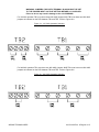
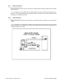
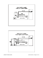
Argus Switched Mode
Battery Charger
010-523-B2
This page intentionally left blank.
Argus Technologies Ltd.
Burnaby, British Columbia. Telephone: 604 436 5900 Fax: 604 436 1233
Argus Technologies reserves the right to make changes to the products and information contained in this document without notice.
Copyright 2008 Argus Technologies Ltd. Argus® is a registered trademark of Argus Technologies Ltd. All Rights Reserved.
Printed in Canada.
Visit www.argus.ca
Argus Switched Mode
Battery Charger
010-523-B2
The following documents and drawings are included in this manual to provide the necessary information required for routine
operation and fault diagnosis of the unit.
• Specifications:
010-523-B1 Rev A
• CSA/NRTL Equivalence:
048-554-10
• Warranty Policy:
048-507-10
• Installation and Operation Instructions:
010-519-C0 Rev A
• Outline Drawing:
010-519-06
• Factory Service Information:
048-527-10
Argus Technologies Ltd.
Printed in Canada. © 2005 Argus Technologies Ltd. ARGUS is a registered trademark of Argus Technologies Ltd. All Rights Reserved.
010-523-B2 Rev C WC
SPECIFICATIONS FOR ARGUS TECHNOLOGIES BATTERY CHARGER, 24 V / 10 A
Battery Output:
Voltage:
Float: 24-30 VDC
Equalize: Float + 2.0 V
Current:
10 ADC
Power:
250 Watts Continuous
Regulation:
< 1.0% line and load (static)
< 10% deviation for 10% to 90% load step (dynamic)
<2 ms to +/-1.0% of output for 10% to 90% load step
Temperature Stability:
<200 ppm/degree C over the operating range
Noise:
Less than 32 dBrnc (Voice Band)
Less than 50mVrms to 10MHz (Wide Band)
Less than 150mVp-p to 100MHz (Wide Band)
Output Protection:
Current Limiting Circuitry, Output Fuses, Over-Voltage Shutdown
Withstands ESD to 15kV, Battery Reversal Protection
System Output:
Voltage:
24V Battery Output
High impedance when not on battery
Noise:
Less than 32 dBrnc (Voice Band)
Less than 50mVrms to 10MHz (Wide Band)
Less than 150mVp-p to 100MHz (Wide Band)
Protection:
Inline 60A (maximum) fuse between battery and charger
Withstands ESD to 15kV
Battery Transfer Time:
< 1 ms
Argus Technologies Ltd.
010-523-B1 Rev. A Page 1 of 3
Input:
Voltage:
85-140 VAC (47-63 Hz)
180-264 VAC (47-63 Hz)
Current:
3.7 Amps (120 VAC nominal) @ 250 Watts output
1.9 Amps (240 VAC nominal) @ 250 Watts output
Power Factor:
Greater than 0.75 (True PF) @ 100% load, nominal input voltage
Efficiency:
76% minimum @ 100% load, nominal input voltage
Input protection:
Input Fuses
Withstands 300VAC for 1 second with no failure
(input configured for 240VAC)
Withstands ESD to 15kV
Recommended Feeder Breaker: 7 Amps or greater (120VAC)
4 Amps or greater (240VAC)
Mechanical:
Size:
3.5" H x 17.0" W x 10.0" D
(8.9cm H x 43.2cm W x 25.4cm D)
Mounting:
19" or 23", center or flush mount, or stand alone
Minimum 1.75" free air space above unit for cooling
Weight:
14 lbs (6.4 kg)
Acoustic Noise:
45 dBA at three feet (one metre)
Connections:
Input:
Output:
Alarms:
Temp. Comp.:
Standard IEC-320 AC Inlet
1/4" studs
Terminal Block #24-#18 AWG
Terminal Block #24-#18 AWG
Argus Technologies Ltd.
010-523-B1 Rev. A Page 2 of 3
Environmental:
Cooling:
Natural Convection
Temperature:
-30ºC to +60ºC (-22ºF to +140ºF) (operating)
Humidity:
0-95% Relative Humidity @ +50ºC (non-condensing)
Elevation:
-500 to +2000 metres (-1640 to 6560 feet)
*ELEVATION ABOVE 2000m: The maximum operating
temperaure can be linearly derated to 40°C at 6000m.
Derating is due to reduced cooling efficiency.
Standards met:
CSA:
UL:
CENELEC:
FCC:
EMC
“
CE ” Mark
950 (Certified under the NRTL program)
1950 (As part of the CSA NRTL program)
EN 60950
Part 15, Sub J Class B (radiated and conducted emissions)
EN 50081-1 to EN 55022 Class A Only
EN 50082-1
Per Directive 89-336-EC “EMC”
In Accordance with FCC requirements, we provide the following statement as specified in the FCC guidelines for
conformance to Part 15 Subpart J, Level B:
WARNING: This equipment generates, uses, and can radiate radio frequency energy and if not
installed and used in accordance with the instruction manual, may cause interference to
radio communications. It has been tested and found to comply with the limits for a Class
B computing device pursuant to Subpart J of Part 15 of the FCC Rules, which are
designed to provide reasonable protection against such interference when operated in a
residential environment. However there is no guarantee that interference will not occur
in a particular installation. If this equipment does cause interference to radio or
television reception, which can be determined by turning the equipment off and on, the
user is encouraged to try to correct the interference by one or more of the following
measures: a) Relocate the unit with respect to the receiver; b:) Move the unit away from
the receiver; c) Plug the unit into a different outlet so that unit and receiver are on
different branch circuits. If necessary, consult dealer or an experienced radio technician
for additional suggestions. :WARNING
Argus Technologies Ltd.
010-523-B1 Rev. A Page 3 of 3
WARRANTY AND REPAIR INFORMATION
Warranty Policy
Argus Technologies Ltd. warrants all equipment manufactured by it to be free from defects in parts
and labor, excluding third party OEM materials (example: air conditioners, batteries), for a period of
two years from the date of shipment from the factory. For third party products the OEM’s warranty
shall apply. The liability of Argus applies solely to repairing, replacing or issuing credit (at Argus’ sole
discretion) for any equipment manufactured by it and returned by the customer during the warranty
period. The terms of the warranty are Ex Works (EXW) from Argus’ factory service location.
Argus reserves the right to void the warranty if:
(1) identification marks or serial numbers are removed or altered in any way,
(2) invoice is unpaid, or
(3) defect is the result of misuse, neglect, improper installation, environmental
conditions, non-authorized repair, alteration or accident.
Argus shall not be liable to the customer or other parties for any loss of profits, loss of use, costs for
removal or installation of defective equipment, damages or consequential damages based upon
equipment failure during or after the warranty period. There shall be no other obligations either
expressed or implied. Argus will not honor warranties for batteries and other third party products
without prior written Argus authorization.
Freight Policy
Customer is responsible for all shipping and handling charges (COD and freight collect will not be
accepted without prior approval from Argus Technologies).
Terms of Payment (North America)
Payment terms are net 30 days subject to prior credit approval. All other orders require payment
before shipping.
Terms of Payment (International)
Payment terms are subject to prior approval and are typically through Tele-Transfer.
Return Material Policy
Our RMA policy is designed to ensure prompt, efficient and high quality factory service. A Return
Material Authorization (RMA) number must be obtained before products can be accepted for
servicing by the Argus factory. For returns to an authorized service center (refer to “Authorized
Service Centers” for locations), please consult the individual service center for specific return policies
and instructions.
To obtain a RMA number for a factory return, customers must call the appropriate location with the
product serial and model number, as well as a brief description of the problem, shipment instructions
and billing details.
The original packing container should be used whenever possible. Both the shipping documents
and the outside of the box must have the RMA # clearly marked and the product shipped prepaid to
the Argus factory service center. Argus will endeavor to repair products within five working days of
receipt. Repairs to the returned product are warranted for a period of six months. A service charge
may be applied if no fault is found in the returned product. Argus will not accept products without an
RMA number.
Business Hours
Argus North American office hours are 7:30 am to 5:00 pm (Pacific Standard Time) Monday to Friday.
Factory Service Centers
Canada and International
Argus Technologies Ltd.
ATTN: RMA Returns
7033 Antrim Avenue
Burnaby, BC, V5J 4M5 Canada
Tel:
+1 604 436 5900
+1 604 436 1233
Fax:
Email: [email protected]
USA
Argus Technologies Inc.
ATTN: RMA Returns
3116 Mercer Avenue
Bellingham, WA, 98225 USA
Tel:
+1-360 756 4904
+1-360 647 0498
Fax:
Email: [email protected]
Asia-Pacific
PCM Electronics (Dong Guan) Co., Ltd.
Hongli Industrial Area, Miaobian, Liaobu Town,
Dongguan City, Guangdong Province,
523400 China
Tel:
+86 755 8895 3310
+86 755 8895 3307
Fax:
Authorized Service Center
Argentina
Argus Technologies de Argentina
Belen 315, Capital Federal, Buenos Aires,
1407l Argentina
Tel:
+54 (11) 4672 4821
+54 (11) 4504 4698
Fax:
Cell:
+54 9 (11) 4993 9996
Email: [email protected]
Asia
Argus Technologies Asia Pte Ltd
Blk 6 Tagore Lane #160
Singapore 787570
Tel:
+65 6458 8900
+65 6458 2122
Fax:
Australia
CPS National
8/376 Newbridge Rd
Moorebank, NSW, 2170 Australia
Tel:
+61 02 9822 8977
+61 02 9822 8077
Fax:
Australia/New Zealand
Alpha Power Systems Pty Ltd
Unit 3, 30 Heathcote Road
Moorebank, NSW, 2170 Australia
Tel:
+61 02 9602 8331
+61 02 9602 9180
Fax:
Century Yuasa
37 - 65 Colbalt Street
Carole Park QLD 4300
Australian Sales & Service
Tel:
+61 07 3361 6587
+61 07 3361 6705
Fax:
New Zealand Sales & Service
Tel:
+64 9 978 6689
+64 9 978 6677
Fax:
Canada
Compower Systems Inc.
118 Tiffield Road
Toronto, ON, M1V 5N2 Canada
Tel:
+1 416 293 3088
+1 416 293 0671
Fax:
Europe
Alpha Technologies Europe Ltd.
Cartel Business Estate
Edinburgh Way
Harlow, Essex, CM20 2DU UK
Tel:
+44 1279 422110
+44 1279 423355
Fax: Mexico & Central America
Technologies Argus First De Mexico SA de CV
Anatole France No. 17
Col. Polanco
Mexico City, 11560 Mexico
Tel:
+52 55 5280 6990
+52 55 5280 6585
Fax: South America
Argus Technologies Argentina
Santo Tome 2573, Capital Federal
Buenos Aires, 1416 Argentina
Tel:
+54 11 4504 4698
+54 9 11 4993 9996
Cell:
E-pager: [email protected]
Turkey
IPC Enerji Elk San ve TIC AS
Inonu cad. Kanarya sok. No:20
Yenisahra - Kadikoy
Istanbul, Turkey
Tel:
+90 216 317 41 42
+90 216 472 90 66
Fax:
048-507-10-I1 Rev S (09/2007)
Canada and USA toll free 24 hour emergency technical support: +1 888 GO ARGUS (462 7487) Outside North America: +1 604 436 5547
CSA/NRTL — MARKS — BACKGROUND
What are the CSA and NRTL?
CSA (Canadian Standards Association also known as CSA International) was established in 1919 as
an independent testing laboratory in Canada. CSA received its recognition as an NRTL (Nationally
Recognized Testing Laboratory) in 1992 from OSHA (Occupational Safety and Health Administration) in
the United States of America (Docket No. NRTL-2-92). This was expanded and renewed in 1997, 1999,
and 2001. The specific notifications were posted on OSHA’s official website as follows:
Federal Register #: 59:40602 - 40609 [08/09/1994]
Federal Register #: 64:60240 - 60241 [11/04/1999]
Federal Register #: 66:35271 - 35278 [07/03/2001]
The product on which either of these marks appear
has been certified by CSA as meeting applicable
Canada/US standards.
When these marks appear with the indicator “C and US” or “NRTL/C” it means that the product is
certified for both the US and Canadian markets, to the applicable US and Canadian standards. (1)
Argus rectifier and power system products, bearing the aforementioned CSA marks, are
certified to CSA C22.2 No. 950 and UL 1950, or CSA/UL 60950.
As part of the reciprocal, US/Canada agreement regarding testing laboratories, the Standards Council
of Canada (Canada’s national accreditation body) granted Underwriters Laboratories (UL) authority to
certify products for sale in Canada. (2)
Only Underwriters Laboratories may grant a licence for the use of this mark, which indicates compliance
with both Canadian and US requirements. (3)
The product on which this mark
appears has been certified by UL
as meeting applicable Canada/US
standards.
What are NRTLs and what do they do?
NRTLs are third party organizations recognized by OSHA, US Department of Labor, under the NRTL
program.
The testing and certifications are based on product safety standards developed by US based standards
developing organizations and are often issued by the American National Standards Institute (ANSI). (4)
The NRTL determines that a product meets the requirements of an appropriate consensus-based
product safety standard either by successfully testing the product itself, or by verifying that a contract
laboratory has done so, and the NRTL certifies that the product meets the requirements of the product
safety standard. (4)
When was the NRTL started and who governs it?
In 1983, in a suit brought on by an independent testing laboratory, OSHA was court ordered to remove
specific references to UL (Underwriters Laboratories) and FMRC (Factory Mutual Research Corporation)
from its regulations.
In 1988, OSHA revised its regulations to remove those references and the NRTL program was
established.
The NRTL Program is both national and international in scope with foreign labs permitted.
References:
Information in this document has been developed from the official websites of the respective
organizations.
(1) www.csa-international.org
(2) www.scc.ca
(3) www.ulc.ca
(4) www.osha.gov
048-554-10-I1 Rev C (2004/02)
argusdcpower.com
MANUAL ADDENDUM
Unit Description: Argus Switch Mode Battery Charger
Manual P/N: 010-519-C0
Applies to Manual Revision: A
#
1
Date
00-06-13
2
Page#
11
Line#
25
15
all
Correction to be implemented
Insert:
Connect the shield of temperature probe one to E14 and connect the shield
of temperature probe two to E15.
Disregard this page. Refer to document 048-527-10, included with this
manual, for factory service information.
3
4
5
6
7
8
9
MANUAL ADDENDUM
Authorized by:
FORM 954-010-10
010519c1.doc
MANUAL ADDENDUM
Unit Description: Argus Switched Mode Battery Reverting Charger
Manual P/N: 010-519-C0
Applies to Manual Revision: A
#
1
2
Date
03-06-11
Page#
All
2
Line#
Any
9
Correction to be implemented
Change “Battery Charger” to “Battery Reverting Charger”
Insert the following (under General/Introduction):
The Argus Battery Reverting Charger must be used with a load that has its own internal power supply. The charger is
not intended to power the load directly.
A complete system consists of the Argus Battery Reverting Charger, batteries, load with power supply, and an AC
source. The system provides a separate charging source and automatic-revert to a battery bank in the event of
an AC power interruption. The Argus Battery Reverting Charger system interfaces with the load’s normal supply
source (or the standard power supply).
The internal supply will supply the load under normal conditions. In the event that the AC source has failed, the
charger initiates a transfer process whereby the battery is connected to supply the load (see Features and
Operation sections).
3
2
9
Insert Figures (below):
Figure 1–Front view of Battery Reverting Charger (010-519-20 typical)
Figure 2–Front panel of 12V 20A Battery Reverting Charger (010-519-20)
MANUAL ADDENDUM
Authorized by:
FORM 954-010-10
010519c0a__2ndAddendum Page 1 of 2
#
4
Date
Page#
5
Line#
11
Correction to be implemented
Insert Figure (below):
Figure 3–Front panel of 24V 10A Battery Reverting Charger (010-523-20)
5
7
6
5.0
13
34
Insert (under Installation/AC Connections):
All
Connect appropriate end of charger power cable to AC supply. The AC
feeding the charger should be the same source feeding the load power
supply. Proceed to the next section, AC Voltage Selection, before
connecting other end of charger power cable to charger.
Replace page (Operation section) with the following:
OPERATION
5.1
Startup
Ensure all power and alarm connections are secure and the AC input voltage selection jumpers are set correctly
(see AC Voltage Selection under Installation Instructions for details). Re-install the back cover and plug the AC
cable into the rear of the unit (drawing 010-519-06, page 2).
The battery fuse(s) should be installed after AC power has been applied to the charger and the POWER ON LED
is illuminated. Although this procedure is not critical it will ensure a more controlled charging of the output filter
capacitors, and power up of the control circuitry in the charger.
To properly start up and test the battery reverting charger the DC connections to the load, AC connections for
both the charger and for the connected load must be connected.
Turn on the AC power to both the charger and the connected load. The load will be powered by its own internal
supply and the charger will be charging the system battery.
5.1.1 Test Transfer Function
Remove AC power from both the battery revert charger and the connected equipment. With the AC removed the
charger will connect the battery to the load instantly.
Reconnect AC power to both the charger and the connected load and the charger will disconnect the battery from
the communications equipment and will start recharging the battery. The communications equipment will now be
powered from its own internal power supply.
Note: Due to the nature of the transfer sensing circuitry section 5.1.1 is the only effective method of testing the
transfer circuitry. Bench testing the charger without the connected load will not effectively test the transfer function.
5.2
Shutdown
Ensure the battery is not connected to the load (the ON BATTERY LED(s) are off). Remove the battery fuse(s).
Unplug the AC cable from the rear of the charger.
5.3
Default Operating Mode
The charger’s default operation is in Float mode. The POWER ON and FLOAT MODE LEDs are illuminated.
To change from FLOAT mode to EQUALIZE mode press and hold the FLOAT/EQUALIZE Mode button for 3
seconds. When the charger changes to EQUALIZE mode the output voltage will increase (see Battery Output
Voltage specifications). Pressing this button again will revert to FLOAT mode (no 3 second delay).
NOTE: Refer to Sections 3.3 and 3.4 regarding Equalize mode, controls and other features of charger operation.
5.3.1 Typical System (Transfer Process)
During AC power, the purpose of the charger is to charge and maintain the battery bank in a Float mode with
automatic equalization every 30 days. The battery bank becomes the source of power to the load when AC power
fails, and the charger is turned off.
Under AC power fail condition, the automatic revert circuit detects this condition and connects the load to the
battery for backup battery operation. After normal AC power is restored, the battery and charger are automatically
disconnected from the load and, at that time, the charger will begin to recharge the battery.
MANUAL ADDENDUM
Authorized by:
FORM 954-010-10
010519c0a__2ndAddendum Page 2 of 2
IMPORTANT SAFETY INSTRUCTIONS
SAVE THESE INSTRUCTIONS - This manual contains important safety and operating
instructions for the Argus battery charger:
1.
Before using battery charger, read all instructions and cautionary markings on:
(1) battery charger, (2) battery, and (3) product using battery.
2.
CAUTION - To reduce risk of injury, charge only lead-acid or NiCad type rechargeable
batteries. Other types of batteries may burst causing personal injury and damage.
3.
Do not expose charger to rain or snow.
4.
Use of an attachment not recommended or sold by the battery charger
manufacturer may result in a risk of fire, electric shock, or injury to persons.
5.
Do not operate charger if it has received a sharp blow, been dropped,
or otherwise damaged in any way; take it to a qualified service center.
6.
Do not disassemble charger; take it to a qualified service center when service or repair
is required. Incorrect reassembling may result in a risk of electrical shock or fire.
INSTALLATION AND OPERATOR'S MANUAL FOR ARGUS BATTERY CHARGER
Table of Contents
1.0
2.0
3.0
4.0
WARRANTY
DOCUMENTATION - PART NUMBER INFORMATION .........................................................................1
2.1
Introduction..................................................................................................................................1
2.2
ARGUS Numbering system ........................................................................................................1
GENERAL ................................................................................................................................................2
3.1
Scope ..........................................................................................................................................2
3.2
Introduction..................................................................................................................................2
3.3
Features ......................................................................................................................................2
3.3.1
Battery Transfer Circuit:..............................................................................................2
3.3.1.1 Current Flowing into Battery: ......................................................................2
3.3.1.2 Connecting the Battery to the Load: ..........................................................2
3.3.1.3 Manually disconnecting the battery from the load. ....................................2
3.3.1.4 Automatically disconnecting the battery from the load: .............................3
3.3.1.3.1 .....AC Failed at time of transfer ..................................................3
3.3.1.3.2 .....AC Valid at time of transfer ...................................................3
3.3.2
Low Voltage Disconnect (LVD):..................................................................................3
3.3.3
Auto Equalize:.............................................................................................................4
3.3.4
Over Voltage Protection (OVP) Reset: .......................................................................4
3.3.5
Temperature Compensation: ......................................................................................4
3.3.6
Reverse Battery Protection.........................................................................................5
3.4
Controls and Indicators: ..............................................................................................................5
3.4.1
Power On Indicator: ....................................................................................................5
3.4.2
Battery Disconnect (Reset) Switch: ............................................................................5
3.4.3
Float Mode Indicator: ..................................................................................................5
3.4.4
Float/Equalize Mode Switch: ......................................................................................5
3.4.5
Equalize Mode Indicator: ............................................................................................5
3.4.6
Temperature Compensation Mode Indicator: .............................................................5
3.4.7
Voltage Down and Voltage Up Pushbuttons (12V and 24V sections): ......................6
3.4.8
Over Voltage Protection Indicator (12V and 24V sections): ......................................6
3.4.9
Low Voltage Disconnect Indicator (12V and 24V sections): ......................................6
3.4.10
Charger Fail Indicator (12V and 24V sections): .........................................................6
3.4.11
On Battery Indicator (12V and 24V sections):............................................................6
3.4.12
Test Points (12V and 24V sections):..........................................................................6
3.4.13
Output Current Indicators (12V and 24V sections): ...................................................6
INSTALLATION INSTRUCTIONS............................................................................................................7
4.1
Tools Required............................................................................................................................7
4.2
Inspection ....................................................................................................................................7
4.3
Preparation/Mounting ..................................................................................................................7
4.4
Connections ................................................................................................................................7
4.4.1
AC Connections ..........................................................................................................7
4.4.2
AC Voltage Selection..................................................................................................8
4.4.3
Battery Connection .....................................................................................................9
4.4.4
Load Connection.........................................................................................................9
4.4.5
Alarm Contacts Connections ......................................................................................11
4.4.5.1 On Battery Alarm ........................................................................................11
4.4.5.2 Over Voltage Protection Alarm ...................................................................11
4.4.5.3 Charger Fail Alarm .....................................................................................11
4.4.6
Temperature Compensation Probe Installation ..........................................................11
5.0
6.0
7.0
OPERATION
....................................................................................................................................13
5.1
Startup.........................................................................................................................................13
5.2
Shutdown ....................................................................................................................................13
SETTINGS / ADJUSTMENTS .................................................................................................................14
6.1
Factory Settings ..........................................................................................................................14
6.2
Adjustments.................................................................................................................................14
6.2.1
Adjustment Ranges.....................................................................................................14
6.2.2
Voltage Adjustment.....................................................................................................14
6.2.3
Voltage Adjustments With Temperature Compensation ............................................14
FACTORY SERVICE INFORMATION.....................................................................................................15
7.1
Moving And Storage ...................................................................................................................15
2.0
DOCUMENTATION - PART NUMBER INFORMATION
2.1
Introduction
Please read this manual thoroughly prior to use in order to become familiar with the unit's numerous
features and operating procedures. To obtain a maximum degree of safety, follow the prescribed
sequences as outlined.
This manual incorporates warnings and notes to the user. Points that are vital to the proper operation or safety of the operator are indicated by the heading: WARNING. Points that are important to
the performance or ease of use of the equipment are covered by a notation that is double underlined.
Items that refer to physical components or features such as indicator lights will be in Bold Italic
typeface. Items that refer to states or modes or generated messages will be in BOLD UPPERCASE typeface.
2.2
ARGUS Numbering system
ARGUS Technologies uses a eight digit drawing number system which is broken into three blocks.
The first three digits describe the category of the product ie. rectifier or fuse panel. The next three
digits indicate the sequence in which the product number was allocated in a particular category.
The last two digits indicate the type of drawing ie:
05 . . . . . . . . . . . . . . . . . Schematic
06 . . . . . . . . . . . . . . . . . . Outline Drawing
20 . . . . . . . . . . . . . . . . . Main Assembly
ARGUS Technologies uses a eight digit part numbering system for all components and sub assemblies. Each part is covered by its own unique number. Due to the quantity categories will not be
listed within this manual.
010-519-C0 Rev. A Page 1 of 15
ARGUS TECHNOLOGIES
3.0
GENERAL
3.1
Scope
This instruction manual covers the installation, and operation of Argus Technologies' Battery
Charger.
3.2
Introduction
The Argus Battery Charger employs a high frequency switched mode conversion technique to provide a fully regulated and isolated DC output from the A.C. mains. The unit provides external connections for input, output and alarm interfaces. The units are available in 12V single output, 24V
single output and 12V/24V dual output models.
3.3
Features
The following sections (3.3.1 through 3.3.6) will cover the various features available on the Argus
Battery Charger.
3.3.1
Battery Transfer Circuit:
The transfer process (connecting the battery to the load) is hardware controlled and so transfer can
occur even in the event the micro-controller is not functioning. The charger firmware can disconnect the battery from the load in one of two ways.
1) Standard Disconnect: The micro-controller disconnects the load but does not disable the
transfer circuitry. If the load power supply is not functioning the load voltage will drop to the
transfer voltage (about 11.5V) and the transfer circuit will reconnect the battery.
2) Hard Disconnect: The relay connecting the battery to the load will be forced off and the
transfer circuitry will be disabled for 10 seconds. The transfer circuitry will re-enable afer the
load voltage has; a) risen about 0.2V (0.4V) above the battery voltage, or b) fallen to the low
voltage disconnect level. The transfer circuitry will then be reenabled in preparation for the next
transfer. The load will be disconnected from the battery regardless of the condition of the load
power supply.
3.3.1.1
Connecting the Battery to the Load:
The transfer circuit will connect the batteries to the load in less than 1 ms from the time the voltage
at the output of the charger (connected to the load) drops to 11.5V from greater than 12.0V.
The load voltage must exceed 12.0 V in order to reset the transfer circuitry. If the load voltage
does not rise above 12.0 V before failing transfer may not occur.
The charger will turn off as soon as a transfer takes place.
3.3.1.2
Manually disconnecting the battery from the load.
To manually disconnect the battery from the load press the battery disconnect switch located on the
front panel of the charger. The charger will do a hard disconnect.
ARGUS TECHNOLOGIES
010-519-C0 Rev. A Page 2 of 15
3.3.1.3
Automatically disconnecting the battery from the load:
When a transfer occurs the batteries will be connected to the load for a minimum of 2 seconds.
After this period has expired the following will dictate when and how the battery is disconnected
from the load:
3.3.1.3.1
Current flowing into the battery:
When the control circuitry detects current flowing (about 3A) into the battery a standard disconnect will be performed regardless of the battery or load voltage.
If 6 standard disconnects have been attempted and the battery has not been disconnected a
hard disconnect will be asserted.
3.3.1.3.2
AC Failed at time of transfer
When a transfer takes place the charger checks to see if the AC source has failed. The
charger assumes the AC feeding the charger is the same source that feeds the load power supply.
When AC power returns the charger will do a standard disconnect about once per second for
about 6 seconds. If the charger has been unsuccessful in disconnecting the battery from the
load it will do a hard disconnect.
3.3.1.3.3
AC Valid at time of transfer:
This condition would occur if the load power supply were to fail or turn off for some reason
other than loss of AC power.
When the load power supply has returned it will start sourcing current into the battery. The
charger will perform a standard disconnect when the battery voltage exceeds 12.0V (24.0V) and
one of the following conditions becomes true:
1) The battery voltage is increasing at a rate that would indicate normal power has been restored to the load.
2) The voltage at the system output of the charger connector exceeds the last float voltage
less 0.25V (0.5V for the 24V battery).
In the event the load is disconnected and the normal power supply for the load has not returned
the transfer circuit will immediately reconnect the batteries to the load. The battery will be connected to the load for a minimum of 2 seconds.
3.3.2
Low Voltage Disconnect (LVD):
After the battery voltage drops to a critical voltage of 10.8 V (21.6 V) the transfer circuit(s) will deenergize the load relay(s) and disconnect the batteries from the load.
For the dual voltage charger the 24 V output will disconnect independently from the 12 V output. If
the 12 V output drops to the critical level both outputs will be disconnected from the load.
010-519-C0 Rev. A Page 3 of 15
ARGUS TECHNOLOGIES
AC power must be restored and the battery voltage must rise to 12.0 V (24.0 V) before the LVD
condition is cleared.
The low voltage disconnect will not function if the micro-controller is not functioning.
There will still be a maximum current draw of 60 mA on the battery (12 V or 24 V) for single output
systems and 80 mA from the 12 V battery and 20 mA from the 24 V battery in dual output systems
after battery cutoff to power some indicator LEDs and other circuitry needed to moniter the condition of the batteries and charger.
During low battery voltage cutoff all alarm relays will be deenergized (indicating: Charger Fail, NOT
On Battery and NOT Overvoltage Shutdown) regardless of the condition of the alarm.
3.3.3
Auto Equalize:
The unit will automatically change to EQUALIZE mode after being in float mode for 30 days. It will
remain in EQUALIZE mode for 24 hours and then automatically revert back to FLOAT mode.
When the charger changes to EQUALIZE mode the output voltage will increase (see Battery Output
Voltage Specification)
Individual cell voltages in a battery tend to drift over time unless the battery is cycled. The overall
battery voltage remains constant but some cell voltages will increase while others decrease.
Increasing the battery voltage periodically tends to equalize the individual cell voltages which optimizes the battery reserve time and overall life expectancy.
3.3.4
Over Voltage Protection (OVP) Reset:
The unit will automatically reset an OVP trip up to 3 times in 1 minute. If more than 3 OVP trips occur in 1 minute, the unit will latch off. The unit can be restarted by pressing the RESET switch.
3.3.5
Temperature Compensation:
Compensation will be linear 21 mV / °C (12 mV / °F) for the 12 V output and 42 mV / °C (24 mV /
°F) over the temperature range 0 °C to +50 °C (+32 °F to +122 °F).
The temperature compensation has provision for 1 or 2 temperature probes. The second probe is
for redundancy and is not intended to compensate a second battery string.
If two probes are used they must be located in the same area. If the probes are placed in different
locations and a temperature difference of greater than 5 °C (9 °F) exist between the probes the
compensation will be turned off and the TEMP COMP LED will flash. The charger will reset the voltage to the nominal float voltage at +25°C (+77 °F).
If the probes indicate a temperature above +100 °C (+212 °F) or below -75 °C (-103 °F) temperature compensation will be turned off and the TEMP COMP LED will flash. The charger will reset
the voltage to the nominal float voltage at +25°C (+77 °F).
See 'Temperature Compensation Probe Installation' for details on probe location and installation.
ARGUS TECHNOLOGIES
010-519-C0 Rev. A Page 4 of 15
3.3.6
Reverse Battery Protection:
In the event the battery is installed backwards fuse(s) F4 (F200) in the charger will blow. Ensure
fuses are replaced with the proper rated fuse(s).
Fuse
F4
F200
Rating
30 A / 65 VDC Very Fast Blow
10 A / 65 VDC Very Fast Blow
Manufacturer
Buss: GBB - 30 or equiv.
Buss: GBB - 10 or equiv.
The SCRs and relays to the load will not close unless a valid battery voltage is present. Installation
instructions must be followed during installation of the charger and batteries.
3.4
Controls and Indicators:
The following sections (3.4.1 through 3.4.13) will cover the various controls and indicators available
on the Argus Battery Charger.
3.4.1
Power On Indicator:
Green LED marked Power On. This LED is on when AC is applied to the charger.
3.4.2
Battery Disconnect (Reset) Switch:
Momentary push button marked BATT DISC (Reset). Pressing this switch will disconnect the battery from the load and reset the micro-controller. The unit will turn off as long as the reset switch is
depressed.
3.4.3
Float Mode Indicator:
Green LED marked Float Mode. This LED is on whenever the unit is on and in FLOAT mode.
3.4.4
Float/Equalize Mode Switch:
Momentary push button located between the float mode and equalize mode LED indicators. To
change from FLOAT mode to EQUALIZE mode press and hold this button for 3 seconds. When the
charger changes to EQUALIZE mode the output voltage will increase (see Battery Output Voltage
specifications). Pressing this button again will revert to FLOAT mode (no 3 second delay). The
unit will remain in EQUALIZE mode up to a maximum of 24 hours before automatically reverting to
FLOAT mode.
3.4.5
Equalize Mode Indicator:
Amber LED marked Equalize. This LED is on whenever the unit is on and in EQUALIZE mode.
3.4.6
Temperature Compensation Mode Indicator:
Amber LED marked Temp Comp. This LED is on whenever the unit is actively compensating the
battery voltage. This LED will flash if a problem exists which prevents proper reliable operation of
the temperature compensation system. The LED will be off when ever the temperature compensation system is disabled.
010-519-C0 Rev. A Page 5 of 15
ARGUS TECHNOLOGIES
3.4.7
Voltage Down and Voltage Up Pushbuttons (12V and 24V sections):
These momentary push button switches will increment and decrement the output voltage of the
charger. Steps are approximately 50mV for the 12 volt output and 100mV for the 24 volt output. If
the unit is in EQUALIZE mode and either of these buttons are pressed then the unit will immediately revert to FLOAT mode. The voltage setting can not be increased while the unit is in CURRENT
LIMIT mode.
3.4.8
Over Voltage Protection Indicator (12V and 24V sections):
Red LED marked OVP. This LED is on whenever the unit has turned off due to an OVER VOLTAGE condition of the output. This LED will always indicate the true condition of the OVP system regardless of a low voltage disconnect unlike the OVP relay.
3.4.9
Low Voltage Disconnect Indicator (12V and 24V sections):
Red LED marked LVD. This LED is on whenever the charger has disconnected the battery from the
load due to a low battery voltage.
3.4.10
Charger Fail Indicator (12V and 24V sections):
Red LED marked FAIL. This LED is on whenever the charger is unable to source power. Possible
fail conditions are AC fail, on battery mode, VOUT < 9 V, fuse fail, unable to source current into the
battery.
3.4.11
On Battery Indicator (12V and 24V sections):
Amber LED marked On Battery. This LED is on whenever the battery is connected to the load.
3.4.12
Test Points (12V and 24V sections):
Test points for 0.080” test probes. The test points indicate the charger output voltage inside the
charger output fuse(s). A 4.99 kohm resistor is in series with both the + and - test points to provide
short circuit protection.
3.4.13
Output Current Indicators (12V and 24V sections):
4 Green LEDs. These LEDs indicate the current flowing from the charger to the battery. Each LED
represents approximately 25% of full load. They do not indicate the amount of current following from
the battery to the load during a transfer. A flashing LED indicates current limit mode.
ARGUS TECHNOLOGIES
010-519-C0 Rev. A Page 6 of 15
4.0
INSTALLATION INSTRUCTIONS
4.1
Tools Required
EXAMPLE:
- Philips screw driver, #2 (Tip Size 3/16")
- Philips screw driver, #3 (Tip Size 1/4")
- Slotted screw driver (Blade size 1/8")
- 7/16" nut driver
- 1/8" diameter non-conductive tool (i.e. tweeker)
- Digital Voltmeter (DVM) with minimum 10 Mohm input impedance
4.2
Inspection
All Argus products are shipped in rugged, double walled boxes and suspended via solid polyurethane foam inserts to minimize shock that may occur during transportion. Packaging assemblies
and methods are tested to National Safe Transit Association standards.
Prior to uncrating of the unit, note any damage to the shipping container. Uncrate the unit and inspect the exterior. If any damage is observed, contact the carrier immediately.
Continue the inspection for any internal damage. In the unlikely event of internal damage please inform the carrier and contact Argus Technologies for advice on the impact of any damage.
4.3
Preparation/Mounting
The unit must be mounted in a clean and dry environment. Sufficient access to an uninterrupted air
source must also be allowed for in front of the unit. Allow at least 1.75 inches of free space above
the unit for cooling.
The unit should be mounted to the rack using two #12 -24 x 1/2" screws in each bracket. A captive
type of drive such as a Philips head is preferred to eliminate the possibility of slippage and scratching of the unit's exterior.
The unit has been designed for mounting in a 19" or 23" EIA standard relay rack. Mounting brackets on this shelf are for 1-3/4" spacing and are reversible for 19" or 23" mounting configurations.
These brackets are shipped from the factory arranged for 19" centre mounting with a 5" offset. To
adapt to 23" mounting, remove the two attaching screws, then flip the brackets so that the large
flange is against the shelf chassis, re-attach with mounting screws. For flush mounting attach the
brackets to the cabinet via the mounting holes located near the front of the cabinet. See the outline
drawing in the back of this manual for details.
4.4
Connections
4.4.1
AC Connections
Standard IEC power cable. Supplies AC power to the charger.
4.4.2
AC Voltage Selection
Terminal blocks TB1 and TB2 accept #18 to #24 AWG wire.
010-519-C0 Rev. A Page 7 of 15
ARGUS TECHNOLOGIES
WARNING: JUMPERS FOR BOTH TERMINAL BLOCKS MUST BE SET
TO THE PROPER INPUT VOLTAGE SETTING BEFORE AC IS APPLIED.
Failure to do so may result in damage to the unit. WARNING
For 120VAC operation TB1 must have three #20 AWG jumpers AND TB2 must have two #20 AWG
jumpers as indicated on the PCB between TB1 and TB2. Refer to Figure #1a.
Figure 1a - 120 VAC Operation Selection
For 240VAC operation TB1 must have two #20 AWG jumpers AND TB2 must have one #20 AWG
jumpers as indicated on the PCB between TB1 and TB2. Refer to Figure #1b.
Figure 1b - 240 VAC Operation Selection
ARGUS TECHNOLOGIES
010-519-C0 Rev. A Page 8 of 15
4.4.3
Battery Connection
Remove the battery fuse(s) before connecting or disconnecting the battery cables from the battery
and/or charger.
1/4” - 20 studs for up to #8 AWG wire. Charger supplies current to the battery through these connections. Current also flows from the battery into these connections to the Load Connection when
the battery is connected to the load.
4.4.4
Load Connection
Remove the battery fuse(s) before connecting or disconnecting the load cables from the load and/or
charger.
1/4” - 20 studs for up to #8 AWG wire. Battery current flows from these terminals to the load during
a transfer condition. The transfer circuit senses the voltage at these terminals to determine when to
connect the battery to the load.
010-519-C0 Rev. A Page 9 of 15
ARGUS TECHNOLOGIES
ARGUS TECHNOLOGIES
010-519-C0 Rev. A Page 10 of 15
4.4.5
Alarm Contacts Connections
4.4.5.1
On Battery Alarm
Terminal block accepts #18 to #24 AWG wire and provides three terminals (Form C contacts) which
are NO, COM and NC. The relay is energized whenever at least one battery is connected to a load.
4.4.5.2
Over Voltage Protection Alarm
Terminal block accepts #18 to #24 AWG wire and provides three terminals (Form C contacts) which
are NO, COM and NC. The relay is energized whenever an OVP (over voltage protection) condition
has occurred and the charger was unable to recover. Note: The OVP relay will be deenergized during a low voltage disconnect even if an OVP condition exists.
4.4.5.3
Charger Fail Alarm
Terminal block accepts #18 to #24 AWG wire and provides three terminals (Form C contacts) which
are NO, COM and NC. The Charger Fail relay is normally energized and will deenergize when
charger fail condition occurs. The charger will indicate a failed condition if it is unable to source
power. Possible fail conditions are AC fail, OVP trip, VOUT < 9 V, fuse fail, on battery (transfer ),
unable to source current into the battery.
The charger incorporates a “voltage ramp” to determine if it is able to source current into the battery. Whenever the output current to the battery drops below 5 % of the rated output, the charger
will intermittently (about once per minute) increase the voltage. This should cause the output current to increase above the 5 % level. As soon as the current rises above 5 %, the ramp will be terminated. If no increase in the output current is detected, the charger fail alarm will be activated.
4.4.6
Temperature Compensation Probe Installation
Terminal block TB4 accepts #18 to #24 AWG wire and provides 3 terminals. `COM' is the common
for the temperature probes (black wire). `1' and `2' are the positive terminal connections for the
temperature probes (red wire).
When one probe is used, terminals '1' and '2' are jumpered together. If the jumper is not installed
the charger will read a discrepancy between probe terminal 1 and 2. See the section 'Temperature
Compensation' for details.
If a second, redundant probe is to be used, the jumper must be removed and the positive (red)
wires from the probes are individually inserted in the terminals marked 1 and 2 and the negative
(black) wires are both inserted into the terminal marked COM.
Generally the temperature probe(s) should be mounted on the battery in the warmest location.
When 2 separate battery strings are used in a system and the batteries are not located in the same
area the probe(s) should be connected to the battery string which is expected to be the warmest.
The temperature probe(s) can be strapped to the center of one side of the battery with an adhesive
tape. If 2 probes are used they should be spaced apart approximately 1" (2.5 cm). When multiple
batteries are used in the system the probe should be placed between the batteries so heating from
the other batteries will be detected by the probes.
010-519-C0 Rev. A Page 11 of 15
ARGUS TECHNOLOGIES
The probe(s) can also be connected directly to a battery terminal. When this is done both probes
must be connected to the same terminal. The probe is electrically isolated from it's tab so it can be
connected to any battery terminal but should be connected to the common terminal of the warmest
battery or battery string.
ARGUS TECHNOLOGIES
010-519-C0 Rev. A Page 12 of 15
5.0
OPERATION
5.1
Startup
Ensure all power and alarm connections are secure and the AC input voltage selection jumpers are
set correctly (see AC Voltage Selection under Installation Instructions for details). Re-install the
back cover and plug the AC cable into the rear of the unit.
The battery fuse(s) should be installed after AC power has been applied to the charger and the
POWER ON LED is illuminated. Although this procedure is not critical it will ensure a more controlled charging of the output filter capacitors, and power up of the control circuitry in the charger.
5.2
Shutdown
Unplug the AC cable from the rear of the unit. Ensure the battery is not connected to the load (the
ON BATTERY LED(s) are off). Remove the battery fuse(s).
010-519-C0 Rev. A Page 13 of 15
ARGUS TECHNOLOGIES
6.0
SETTINGS/ADJUSTMENTS
6.1
Factory Settings
12V Output:
24V Output:
13.7VDC
27.4VDC
AC input voltage selection jumpers set for 120VAC.
6.2
Adjustments
6.2.1
Adjustment Ranges
12V Output
24V Output
6.2.2
12.0VDC to 15.0VDC
24.0VDC to 30.0VDC
Voltage Adjustment
Monitor the output voltage of the charger at the voltage test points when making voltage adjustments. Use a DVM with minimum 10 Mohm input impedance as each test point has a 4.99 kohm
resistor in series for short circuit protection.
The output voltage cannot be increased while the unit is in current limit. If the battery is connected
to the battery output terminals, the voltage may not decrease when the DOWN switch is pressed.
The potentiometer controlling the output voltage will be decremented and may result in an incorrectly adjusted output voltage. The battery may have to be disconnected if a voltage setting lower
than the present battery voltage is desired.
6.2.3
Voltage Adjustments With Temperature Compensation
The temperature compensation system, if active, will be deactivated whenever the output voltage is
adjusted. The compensation offset will be set to zero and the output voltage of the charger can be
adjusted to the desired 25°C (77°F) battery float voltage. The battery may have to be disconnected
until after the voltage is set. Temperature compensation will resume 30 seconds after voltage adjustments are completed.
ARGUS TECHNOLOGIES
010-519-C0 Rev. A Page 14 of 15
This page intentionally left blank.
FACTORY SERVICE INFORMATION
Technical Support
Technical support staff are available for answering general questions related to installation, operation
and maintenance of Argus products. In Canada and the USA, call Argus toll free 7:30 am to 5:00 pm
Pacific Standard Time at:
+1-888 GO ARGUS
(+1-888-462-7487)
For emergencies, call +1-888-GO-ARGUS 24 hours a day, seven days a week.
Customers outside Canada and the USA, call +1-604-436-5547 for technical support.
Training
Argus offers various levels of product and technical training. These workshops provide a mix of
theory and hands on application for qualified customers. Please consult your sales representative for
course schedules, locations and costs, or visit our website at www.argusdcpower.com.
Factory Repair and Servicing
All service, beyond initial adjustments, should be carried out by qualified factory service personnel.
For these procedures, please contact Argus Technologies at the locations listed to the right.
Product Returns
Before returning any product for service, please obtain a Return Material Authorization (RMA) number
from an Argus factory service representative. The representative will require the model and serial
number, as well as a brief description of the problem prior to issuing the RMA number. All material
must be pre-authorized before being returned.
See document 048-507-10 “Warranty and Repair Information” for more details.
Moving and Storage
Units must be suitably packed in the original shipping container (or equivalent) prior to re-shipping.
The box should be completely enclosed and constructed of wood or double-wall, corrugated
cardboard. At least 3” of foam or shock absorbing packing material must surround the unit.
Factory Service Centers
Canada and International
Argus Technologies Ltd.
ATTN: RMA Returns
7033 Antrim Avenue
Burnaby, BC, V5J 4M5 Canada
Tel:
+1 604 436 5900
+1 604 436 1233
Fax:
Email: [email protected]
USA
Argus Technologies Inc.
ATTN: RMA Returns
3116 Mercer Avenue
Bellingham, WA, 98225 USA
Tel:
+1-360 756 4904
+1-360 647 0498
Fax:
Email: [email protected]
Asia-Pacific
PCM Electronics (Dong Guan) Co., Ltd.
Hongli Industrial Area, Miaobian, Liaobu Town,
Dongguan City, Guangdong Province,
523400 China
Tel:
+86 755 8895 3310
+86 755 8895 3307
Fax:
Authorized Service Center
Argentina
Argus Technologies de Argentina
Belen 315, Capital Federal, Buenos Aires,
1407l Argentina
Tel:
+54 (11) 4672 4821
+54 (11) 4504 4698
Fax:
Cell:
+54 9 (11) 4993 9996
Email: [email protected]
Asia
Argus Technologies Asia Pte Ltd
Blk 6 Tagore Lane #160
Singapore 787570
Tel:
+65 6458 8900
+65 6458 2122
Fax:
Australia
CPS National
8/376 Newbridge Rd
Moorebank, NSW, 2170 Australia
Tel:
+61 02 9822 8977
+61 02 9822 8077
Fax:
Australia/New Zealand
Alpha Power Systems Pty Ltd
Unit 3, 30 Heathcote Road
Moorebank, NSW, 2170 Australia
Tel:
+61 02 9602 8331
+61 02 9602 9180
Fax:
Century Yuasa
37 - 65 Colbalt Street
Carole Park QLD 4300
Australian Sales & Service
Tel:
+61 07 3361 6587
+61 07 3361 6705
Fax:
New Zealand Sales & Service
Tel:
+64 9 978 6689
+64 9 978 6677
Fax:
Canada
Compower Systems Inc.
118 Tiffield Road
Toronto, ON, M1V 5N2 Canada
Tel:
+1 416 293 3088
+1 416 293 0671
Fax:
Europe
Alpha Technologies Europe Ltd.
Cartel Business Estate
Edinburgh Way
Harlow, Essex, CM20 2DU UK
Tel:
+44 1279 422110
+44 1279 423355
Fax: Mexico & Central America
Technologies Argus First De Mexico SA de CV
Anatole France No. 17
Col. Polanco
Mexico City, 11560 Mexico
Tel:
+52 55 5280 6990
+52 55 5280 6585
Fax: South America
Argus Technologies Argentina
Santo Tome 2573, Capital Federal
Buenos Aires, 1416 Argentina
Tel:
+54 11 4504 4698
+54 9 11 4993 9996
Cell:
E-pager: [email protected]
Turkey
IPC Enerji Elk San ve TIC AS
Inonu cad. Kanarya sok. No:20
Yenisahra - Kadikoy
Istanbul, Turkey
Tel:
+90 216 317 41 42
+90 216 472 90 66
Fax:
048-527-10-I1 Rev L (09/2007)
Canada and USA toll free 24 hour emergency technical support: +1 888 GO ARGUS (462 7487) Outside North America: +1 604 436 5547