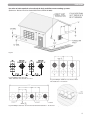
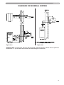
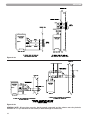
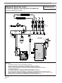
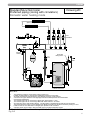
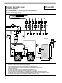
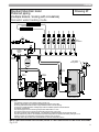
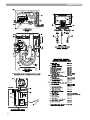
1
Installing, Operating & Maintaining MUNCHKIN™ HIGH EFFICIENCY HEATER with the “925” Controller WARNING If the information in this manual is not followed exactly, a fire or explosion may result causing property damage, personal injury or loss of life. Do not store or use gasoline or other flammable vapors and liquids in the vicinity of this or any other appliance. WHAT TO DO IF YOU SMELL GAS • Do not try to light any appliance. • Do not touch any electrical switch: do not use any phone in your building. • Immediately call your gas supplier from a neighbor's phone. Follow the gas supplier's instructions. • If you cannot reach your gas supplier, call the fire department. Installation and service must be performed by a qualified installer, service agency or the gas supplier. CONTROLS MH27745 WARNING This manual must only be used by a qualified heating installer / service technician. Failure to comply could result in severe personal injury, death or substantial property damage. It is also important to keep these Instructions with the appliance. HEAT TRANSFER PRODUCTS, INC. 120 BRALEY RD., E. FREETOWN, MA 02717 USING THIS MANUAL USING THIS MANUAL SPECIAL ATTENTION BOXES Throughout this manual you will see these special attention boxes similar to this one, which are intended to supplement the instructions and make special notice of potential hazards. These categories mean, in the judgement of Heat Transfer Products, Inc.: NOTICE Heat Transfer Products manufactures both ASME and Non-ASME boilers. It is the responsibility of the installer that the correct model has been selected for jurisdiction requirements. DANGER DANGER indicates an imminently hazardous situation which, if not avoided, will result in death or serious injury. WARNING WARNING indicates a potentially hazardous situation which, if not avoided, could result in death or serious injury. CAUTION CAUTION Indicates a potentially hazardous situtation which, if not avoided, may result in minor or moderate injury. CAUTION CAUTION used without the safety alert symbol indicates a potentially hazardous situation which, if not avoided, may result in property damage. WARNINGS • THIS UNIT IS FOR CATEGORY IV VENTING - 2 PIPE ONLY. THIS IS A SEALED COMBUSTION APPLIANCE. • THIS HEATER INSTALLATION MUST CONFORM TO THE LATEST EDITION OF THE “NATIONAL FUEL GAS CODE” ANSI Z223.1 NFPA 54 AND OR CAN/CGA B149 INSTALLATION CODES. STATE AND LOCAL CODES MIGHT ALSO APPLY TO INSTALLATION. • WHERE REQUIRED BY THE AUTHORITY HAVING JURISDICTION, THE INSTALLATION MUST CONFORM TO THE STANDARDS FOR CONTROLS AND SAFETY DEVICES FOR AUTOMATICALLY FIRED HEATERS, ANSI/ASME HEATER AND PRESSURE VESSEL CODE, Section IV, ALONG WITH CSD1. • THE HEATER, GAS PIPING, WATER PIPING, VENTING AND ELECTRICAL MUST BE INSTALLED BY TRAINED & QUALIFIED PERSONNEL FAMILIAR WITH INSTALLATION PRACTICES, LOCAL CODE, LICENSING REQUIREMENTS. • IF THE INFORMATION IN THESE INSTRUCTIONS ARE NOT FOLLOWED EXACTLY, A FIRE OR EXPLOSION MAY RESULT; CAUSING PROPERTY DAMAGE, PERSONAL INJURY, OR DEATH. • DO NOT STORE OR USE GASOLINE OR OTHER FLAMMABLE VAPORS AND LIQUIDS IN THE VICINITY OF THIS OR ANY OTHER APPLIANCE; • THE USE OF A LOW WATER CUT-OFF DEVICE MAY BE REQUIRED BY STATE OR LOCAL CODES IF THE MUNCHKIN IS INSTALLED ABOVE RADIATION LEVELS. 2 TABLE OF CONTENTS TABLE OF CONTENTS PART 1 . . . . . . . . . . . . . . . . . . . . . .4 thru 8 PART 5 . . . . . . . . . . . . . . . . . . . .22 thru 33 GENERAL INFORMATION PIPING A B C D How It Operates . . . . . . . . . . . . . . . . . .4 Munchkin Ratings and Dimensions . . .4 Pre-installation Requirements . . . . . . .8 Pressure Relief Valve . . . . . . . . . . . . . .9 A Hydronic piping with Circulators or Zone Valves . . . . . . . . .22 Circulator Sizing . . . . . . . . . . . . . . . . .23 Fill and Purge Heating System . . . . . .24 Piping Illustrations . . . . . . . . . . . . . . .25 B C D PART 2 . . . . . . . . . . . . . . . . . . . . .9 thru 11 PART 6 . . . . . . . . . . . . . . . . . . . .34 thru 37 ELECTRICAL A START UP PROCEDURES Electrical Connection . . . . . . . . . . . . . .9 PART 3 . . . . . . . . . . . . . . . . . . . .12 thru 13 GAS CONNECTION A B C Gas Connection . . . . . . . . . . . . . . . . . .12 Gas Piping . . . . . . . . . . . . . . . . . . . . . .12 Gas Table . . . . . . . . . . . . . . . . . . . . . . .12 PART 4 . . . . . . . . . . . . . . . . . . . .14 thru 21 VENTING A B C D E F G General . . . . . . . . . . . . . . . . . . . . . . . .14 Approved Materials for Exhaust Vent and Intake Air Pipe . . . . . . . . . . . . . . .14 Exhaust/Vent / Air Intake Pipe Location . . . . . . . . . . . . . . . . . . . .14 Exhaust Vent and Intake Air Pipe Sizing . . . . . . . . . . . . . . . . . . . . . .16 Exhaust Vent and Air Intake Pipe Installation . . . . . . . . . . . . . . . . . .16 Heater Removal from a Common Vent System . . . . . . . . . . . .18 Condensate Removal . . . . . . . . . . . . .18 A B C D E F G H Sequence of operation . . . . . . . . . . . .34 Items to be checked before lighting the Munchkin . . . . . . . . . . . . .34 Lighting Instructions . . . . . . . . . . . . . .35 Operating Instructions . . . . . . . . . . . .35 Adjusting the Temperature on the Munchkin Display . . . . . . . . . .36 Status Menu . . . . . . . . . . . . . . . . . . . .36 Test Mode . . . . . . . . . . . . . . . . . . . . . .37 To Turn Off Gas to Appliance . . . . . . .37 PART 7 . . . . . . . . . . . . . . . . . . . .38 thru 40 TROUBLESHOOTING A B C Munchkin Error Code . . . . . . . . . . . . .38 Boiler Error . . . . . . . . . . . . . . . . . . . . .38 Boiler Fault . . . . . . . . . . . . . . . . . . . . .38 PART 8 . . . . . . . . . . . . . . . . . . . .40 thru 44 MAINTENANCE A B C D E F Maintenance Procedures . . . . . . . . . .41 Before Each Heating Season . . . . . . .41 Condensate Cleaning Instructions . . .41 Combustion Chamber Coil Cleaning Instructions . . . . . . . . . .42 Munchkin Controller . . . . . . . . . . . . . .43 Components Diagrams . . . . . . . . .44–45 3 GENERAL INFORMATION PART 1. GENERAL INFORMATION A. HOW IT OPERATES When the room thermostat calls for heat, the Munchkin control board will start the circulator and start to monitor the return temperature of the system before the heater will begin to heat the water. Once the controller has sensed a drop in the return water temperature below the temperature set point minus the differential set point, the heater will start to heat the water. This eliminates the Munchkin starting every time the thermostat calls for heat. This feature keeps the system from short cycling. Once the system has sensed the temperature difference, the Munchkin will activate the blower motor for 5 seconds to pre-purge the system before starting the Munchkin. The Munchkin controller will now start to modulate the pre-mix burner based on analyzing the return temperature, supply water temperature and the set point temperature. By compiling this information, the controller utilizes an algorithm to fully adjust the firing rate while maintaining the desired output temperature. The pre-mix burner fan has a direct drive current low-voltage motor with a pulse relay counting. This system allows precise control over the fan speed and combustion air volumes. Coupled with the Dungs gas valve and the the swirl plate system which are set to provide a one-to-one ratio of precisely measured volumes of fuel to air, an accurate and instant burner output is achieved. This keeps the Munchkin running at the highest efficiency. When the thermostat is satisfied, the Munchkin will then go through a 4 second post-purge cycle before shutting off. Every Munchkin heater is equipped with a display which will read the outlet temperature of the heater and then will illuminate a green light showing flame on. If a problem occurs, the front indicator light will turn red and the display will read a fault code; see Part 7, Section B/C. B. MUNCHKIN RATINGS AND DIMENSIONS PERFORMANCE RATINGS Model T50M T80M 80M 140M 199M Input Modulation 18,000 to 50,000 19,000 to 80,000 27,000 to 80,000 46,000 to 140,000 66,000 to 199,000 DOE Heating 16,000 to 46,000 17,000 to 74,000 25,000 to 74,000 43,000 to 129,000 61,000 to 183,000 AFUE 92% 92% 92% 92% 92% Gas Connection Size 3/4" 3/4" 3/4" 3/4" 3/4" Vent Dia. 2" 2" 3" 3" 3" *Net water CONNECTION SIZES Model T50M T80M 80M 140M 199M 4 Supply/Return Connection 1 1/4" NPT 1 1/4" NPT 1 1/4" NPT 1 1/4" NPT 1 1/4" NPT Shipping Weight 58 lbs. 58 lbs. 75 lbs. 101 lbs. 111 lbs. *IBR 40,000 64,000 64,000 112,000 159,000 GENERAL INFORMATION RECOMMENDED SERVICE CLEARANCES (NOTE: The Munchkin is rated at zero clearance to combustibles.) 80M/140M/199M T50M/T80M Figure 1-1 Figure 1-2 5 GENERAL INFORMATION DIMENSIONS T50M/T80M Figure 1-3 6 GENERAL INFORMATION DIMENSIONS 80M Figure 1-4 140M/199M Figure 1-5 7 GENERAL INFORMATION C. PRE-INSTALLATION REQUIREMENT GENERAL 1. Munchkin Boilers are supplied completely assembled as packaged boilers. The package should be inspected for damage upon receipt and any damage to the unit should be reported to the shipping company and wholesaler. This boiler should be stored in a clean, dry area. 2. Carefully read these instructions and be sure to understand the function of all connections prior to beginning installation. Contact your Munchkin Sales Representative or the Heat Transfer Products, Inc. Customer Service Department for help in answering questions. 3. This boiler must be installed by a qualified contractor. The boiler warranty may be voided if the boiler is not installed correctly. 4. This boiler needs to be installed on a level floor. If the floor is not level, the boiler must be pitched back (1/4” pitch for the 80M and 3/8” for the 140/199M.) This will assure proper flow to condensate drain in the bottom of the boiler. CODES & REGULATIONS Installation and repairs are to be performed in strict accordance with the requirements of state and local regulating agencies and codes dealing with boiler and gas appliance installation. WARNING Liquefied Petroleum (LP) Gas or Propane is heavier than air and, in the event of a leak, may collect in low areas such as basements or floor drains. The gas may then ignite resulting in a fire or explosion. ACCESSIBILITY CLEARANCES 1. The Munchkin Boiler is certified for closet installations with zero clearance to combustible construction. In addition, it is design certified for use on combustible floors. 8 2. Refer to Figure 1.1 and Figure 1.2 for the recommended clearance to allow for reasonable access to the boiler. Local codes or special conditions may require greater clearances. CAUTION Do not install this boiler on carpeting. COMBUSTION AND VENTILATION AIR 1. The Munchkin Boiler is designed only for operation with combustion air piped from outside (sealed combustion). PVC pipe must be supplied between the air inlet connection at the rear of the boiler through an outside wall. 2. No additional combustion or ventilation air is required for this appliance. 3. Refer to Section 4 of this manual, Venting, for specific instructions for piping combustion air. PLANNING THE LAYOUT 1. Prepare sketches and notes showing the layout of the boiler installation to minimize the possibility of interferences with new or existing equipment, piping, venting and wiring. 2. The following sections of this manual should be reviewed for consideration of limitations with respect to: a. Electrical Wiring: Part 2 b. Gas Connection: Part 3 c. Venting: Part 4 f. Piping: Part 5 Note: It is important to refer to the site installation checklist in the back of this manual to assure proper and effective installation. GENERAL INFORMATION / ELECTRICAL CAUTION The Munchkin is certified as an indoor appliance. Do not install the Munchkin outdoors or locate where it will be exposed to freezing temperature. This includes all related piping and components. If the Munchkin is subjected to flood water or submersed in water, the Munchkin must be replaced. Note: Service clearance of the Munchkin: See Section 1, Figures 1-1 and 1-2. If the Munchkin is set up for liquefied petroleum (LP) gas, some geographic areas follow the Uniform Mechanical Code, section 304.6, “Liquefied petroleum gas burning appliances shall not be installed in a pit, basement or similar location where heavier-than-air gas might collect. Appliances so fueled, shall not be installed in a below grade under-floor space or basement unless such location is provided with an approved means for removal of unburned gas.” CAUTION Condensation removal: This is a condensing high efficiency appliance, therefore condensation removal must be addressed to avoid damage to surrounding area or appliance. See Part (4) Section E for Condensate Requirements. WARNING D. PRESSURE RELIEF VALVE A pressure relief valve is installed into the front right side manifold. We recommend a WATTS ¾" M 335 MI valve or equivalent and meets the requirements of ANSI/ASME Heater and Pressure Vessel Code, Section IV or CSA B51; Heater, Pressure Vessel and Piping Code as applicable for heating heaters. A ¾" pipe must be directed to a floor drain or suitable location within 6" of a drain or floor. Protect from freezing, do not plug or cap pressure relief valve. Serious explosion causing property damage and or loss of life could result. Under no circumstances should the relief valve be eliminated, capped or plugged. PART 2. ELECTRICAL A. ELECTRICAL CONNECTION The electrical connection for the Munchkin is on the left hand side of the unit. There is a ½” knockout location for an electrical connection for both the incoming power and the central heating circulator connection. All electrical wiring must be performed by a qualified licensed electrician in accordance with National Electrical Code ANSI Z223.1//NFPA 54 to and/or the Canadian Electrical Code, Part 1 CSA C22.1, or to the applicable codes and standards. For your convenience, we have labeled all the wires that need to be connected to operate the Munchkin. 9 ELECTRICAL CAUTION Electrical wiring on the Incoming Power and Central Heating Circulator shall be connected directly to the intended connection source and not be connected together inside the electric box provided. An Electrical Short will result and the Control board will have to be replaced! If Electrical Requirements of the Central Heating Circulator exceeds 4 amps (or 3 amps on HA models only) please follow the wiring diagrams on Figures 2-1, 2-2 and 2-3 (this section). The electrical requirements are for standard 120 volts, 60 Hz 15 Amp service. This unit is wired with #18 awg and fused for no more than 15 Amps. DANGER IT IS EXTREMELY IMPORTANT THAT THIS UNIT BE PROPERLY GROUNDED! DANGER IT IS VERY IMPORTANT THAT THE BUILDING GROUND IS INSPECTED BY A QUALIFIED ELECTRICIAN PRIOR TO MAKING THIS CONNECTION! There are two ground points in the electrical compartment that must be connected to the building ground system. Connect the building ground to the green ground screw and the green ground wire inside electrical box provided. The Incoming Power Supply is connected to the Black (Hot) and the White (Neutral).The Munchkin Control board is polarity sensitive. If the polarity is reversed, the Munchkin control will not sense a flame and lock out the system. The Orange and Brown wire are provided to the supply of 120 volts to the Central Heating Circulator. Connect the Orange (Hot) and the Brown (Neutral) directly to the Central Heating Circulator. DANGER The Orange wire for the Central Heating Circulator is Switched Hot and must have a wire nut if not connected to the Central Heating Circulator. Failure to follow this instruction will result in a short, and the Control Board will have to be replaced. Connect the gray wires to your heating thermostat (TT) connection. Your thermostat heat anticipator setting is .056 amp. CAUTION Do not power zone valves directly from the heater transformer. Doing so will greatly reduce the life of the transformer. Use a separate transformer sized to handle the total electric load of all zone valves. It is important that the electrical power is not turned on at this time. Double check all connections and then turn the power on. The display that is provided with the Munchkin should now be reading the outlet temperature. Note: see Part 6/Startup Procedure section in the manual to change the temperature setting or run the heater. 10 ELECTRICAL DIAGRAM "A" DIAGRAM "B" WIRING DIAGRAM CONNECTING TO CIRCULATOR WIRING DIAGRAM WITHOUT CONNECTION TO CIRCULATOR T GRAY WHITE (NEUTRAL) T BLACK (HOT) GRAY T GREEN (GROUND) GRAY GRAY GREEN (GROUND) T NORMALLY OPEN THERMOSTAT CONNECTION BROWN (NEUTRAL) NORMALLY OPEN THERMOSTAT CONNECTION GREEN (GROUND) ORANGE (HOT) BLACK BROWN (NEUTRAL) WHITE (NEUTRAL) ORANGE (HOT) OR AN GE BR OW GR N EE N GREEN (GROUND) IMPORTANT NOTE: BE CERTAIN THAT THE ORANGE WIRE IS SECURELY CAPED. FAILURE TO DO SO COULD RESULT IN INJURY OR FIRE AND COULD DAMAGE THE CONTROL. WHITE (NEUTRAL) BLACK (HOT) GREEN (GROUND) GROUND BUS ELECTRICAL SWITCH JUNCTION BOX 120V 60 HZ ELECTRICAL SWITCH JUNCTION BOX 120V 60 HZ Figure 2-1: Connection Wiring Directly to Central Heating Circulator ZONE THERMOSTAT R845A SWITCHING RELAY ZONE BOILER "TT" GRAY 1K1 5 Figure 2-2: Connection Wiring without Wiring Central Heating Circulator Note to Electrical Contractor: The orange wire is 120 Volt/4 Amp maximum for central heating circulator only. Loads greater than 4 amps or 3 amps for HA models only will blow the fuse on the board. The brown wire is the neutral wire for the central heating pump only. 3 T T 1K1 1 L1 HOT (BLACK) 120 VOLT 2 1K2 6 4 BOILER "TT" GRAY ZONE CIRCULATOR L2 NEUTRAL (WHITE) Figure 2-3: For circulator amp loads greater than 4 amps (3 amps for “HA” models) use the wiring diagram shown above. The brown and orange wires on the Munchkin boiler will not be used in this application and should be terminated so they do not cause a short circuit. 11 GAS CONNECTION PART 3. GAS CONNECTION WARNING Failure to follow all precautions could result in fire, explosion or death! A. GAS CONNECTION The gas supply shall have a maximum inlet pressure of less than 14" water column (350 mm), ½ pound pressure (3.5 kPa), and a minimum of 3.5" water column. The entire piping system, gas meter and regulator must be sized properly to prevent pressure drop greater than 0.5" as stated in the National Fuel Gas Code. This information is listed on the rating plate. It is very important that you are connected to the type of gas as noted on the rating plate. "LP" for liquefied petroleum, propane gas or, "Nat" natural or city gas. All gas connections must be approved by the local gas supplier, or utility in addition to the governing authority, prior to turning the gas supply on. The nipple provided is ½" and it is mandatory that a ¾" to ½" reducing coupling (provided) is used, threaded into the branch of a ¾" tee, and a drip leg fabricated, as per the National Fuel Gas code. You must ensure that the entire gas line to the connection at the Munchkin is no smaller than ¾". Once all the inspections have been performed, the piping must be leak tested. If the leak test requirement is a higher test pressure than the maximum inlet pressure, you must isolate the Munchkin from the gas line. In order to do this, you must shut the gas off using factory and field-installed gas cocks (following the lighting instructions in Part 6 Section B.) This will prevent high pressure. Failure to do so may damage the gas valve. In the event the gas valve is exposed to a pressure greater than ½ PSI, 14" water column, the gas valve must be replaced. Never use an open flame (match, lighter, etc.) to check gas connections. B. GAS PIPING 1. Run the gas supply line in accordance with all applicable codes. 2. Locate and install manual shutoff valves in accordance with state and local requirements. C. GAS TABLE Refer to Table (1) to size the supply piping to minimize pressure drop between meter or regulator and unit. Maximum Capacity of Pipe in Cubic Feet of Gas per Hour for Gas Pressures of 0.5 psi or Less and a Pressure Drop of 0.3 Inch water Column (TABLE 1) Nominal Iron Pipe Internal Size Diameter (inches) (inches) 10 3/4 .824 278 1 1.049 520 1 1/4 1.380 1,050 1 1/2 1.610 1,600 12 (Based on a 0.60 Specific Gravity Gas) Length of Pipe (Feet) 20 190 350 730 1,100 30 152 285 590 890 40 130 245 500 760 50 115 215 440 670 60 70 105 96 195 180 400 370 610 560 80 90 170 350 530 90 84 160 320 490 100 79 150 305 460 125 72 130 275 410 150 64 120 250 380 175 59 110 225 350 200. 55} 100} 210} 320} BTU'S PER HOUR X 1,000 GAS CONNECTION It is recommended that a soapy solution be used to detect leaks. Bubbles will appear on the pipe to indicate a leak is present. The gas piping must be sized for the proper flow and length of pipe, to avoid pressure drop. Both the gas meter and the gas regulator must be properly sized for the total gas load. If you experience a pressure drop greater than 1" WC, the meter, regulator or gas line is undersized or in need of service. You can attach a manometer to the incoming gas drip leg, by removing the cap and installing the manometer. The gas pressure must remain between 3.5" and 14" during stand-by (static) mode and while in operating (dynamic) mode. If an in-line regulator is used, it must be a minimum of 10 feet from the Munchkin. It is very important that the gas line is properly purged by the gas supplier or utility. Failure to properly purge the lines or improper line sizing, will result in ignition failure. This problem is especially noticeable in NEW LP installations and also in empty tank situations. This can also occur when a utility company shuts off service to an area to provide maintenance to their lines. This gas valve must not be replaced with a conventional gas valve under any circumstances. As an additional safety feature, this gas valve has a flanged connection to the Venturi and blower. DUNGS GAS VALVE THROTTLE ADJUSTER (NOTE: IF FOR ANY REASON THE THROTTLE NEEDS TO BE ADJUSTED, IT IS VERY IMPORTANT THAT A "COMBUSTION ANAYLYZER" BE USED TO ENSURE SAFE AND PROPER OPERATION. TURN THE ADJUSTER TO THE (+) TO INCREASE GAS OR THE (-) TO DECREASE THE GAS SUPPLY. THIS ADJUSTMENT COULD AFFECT CO/CO% LEVELS. MAKE SURE THE LEVELS CORRESPOND TO THE CHART IN COMBUSTION SETTINGS.) Fig. 3-1 WARNING Failure to follow all precautions could result in fire, explosion or death! 13 VENTING PART 4. VENTING A. GENERAL 1. Install the boiler venting system in accordance with these instructions and with the National Fuel Gas Code, ANSI Z223.1/NFPA 54, CAN/CGA B149, and/or applicable provisions of local building codes. 2. This boiler is a direct vent appliance and is listed as a Category IV appliance with Underwriters Laboratories, Inc. VENT AND INTAKE AIR PIPE WARNING This vent system will operate with a positive pressure in the pipe. Do not connect vent connectors serving appliances vented by natural draft into any portion of mechanical draft systems operating under positive pressure. WARNING Follow these venting instructions carefully. Failure to do so may result in severe personal injury, death, or substantial property damage. B. APPROVED MATERIALS FOR EXHAUST VENT AND INTAKE AIR PIPE 1. Use only Non Foam Core venting material. The following materials are approved for use as vent pipe for this boiler: a. Non Foam Core PVC (Polyvinyl Chloride) Pipe conforming to ASTM D-1784 Class 12454-B (formerly designated Type 1, Grade 1). b. Non Foam Core CPVC (Chlorinated Polyvinyl Chloride) Pipe conforming to ASTM D-1784 Class 23447-B (formerly designated Type IV, Grade 1). c. Non Foam Core ABS (AcrylonitrileButadiene- Styrene) Pipe conforming to ASTM D3965 Class 3-2-2-2-2. WARNING Do not use Foam Core Pipe in any portion of the exhaust piping from this boiler. Use of Foam Core Pipe may result in severe personal injury, death, or substantial property damage. 2. Cellular foam core piping may be used on air inlet piping only. Never use cellular foam core material for exhaust piping. 14 C. EXHAUST/VENT / AIR INTAKE PIPE LOCATION 1. Determine exhaust vent location: a. The vent piping for this boiler is approved for zero clearance to combustible construction. b. See Figure 4.1 for an illustration of clearances for location of exit terminals of directvent venting systems. c. This boiler vent system shall terminate at least 3 feet (0.9 m) above any forced air intake located within 10 ft (3 m). Note: this does not apply to the combustion air intake of a direct-vent appliance. d. Provide a minimum of 1 foot distance from any door, operable window, or gravity intake into any building. e. Provide a minimum of 1 foot clearance from the bottom of the exit terminal above the expected snow accumulation level. Snow removal may be necessary to maintain clearance. f. Provide 4 feet horizontal clearance from electrical meters, gas meters, gas regulators, and relief equipment. In no case shall the exit terminal be above or below the aforementioned equipment unless the 4 foot horizontal distance is maintained. g. Do not locate the exit terminal over public walkways where condensate could drip and/or freeze and create a nuisance or hazard. h. When adjacent to a public walkway, locate exit terminal at least 7 feet above grade. i. Do not locate the exit termination directly under roof overhangs to prevent icicles from forming. j. Provide 3 feet clearance from the inside corner of adjacent walls. 2. Determine air intake pipe location. a. Provide 1 foot clearance from the bottom of the air inlet pipe and the level of maximum snow accumulation. Snow removal may be necessary to maintain clearances. b. Do not locate air intake pipe in a parking area where machinery may damage the pipe. c. When venting with a two pipe system, maximum distance between air intake and exhaust vent is 6 feet (1.8 m). Minimum distance between exhaust vent and air intake on single boiler is 8” (0.2 m) center-to-center. Minimum distance between vents and intakes on multiple boilers is 8” (0.2 m) center-to-center. See Figure 4.2. VENTING Location of exit terminals of mechanical draft and direct-vent venting systems. (Reference: National Fuel Gas Code ANSI Z223.1/NFPA 54 2002). Fig. 4.1 Fig. 4.2 Multiple Vent Spacing* *Note: Exhaust must extend out 1 foot Fig. 4.3 Multiple Stainless Steel Vertical Vent Kit Installation – Front View Fig. 4.4 Multiple Stainless Steel Horizontal Vent Kit Installation – Front View Figure 4.5: Multiple Boiler Installations 15 VENTING D. EXHAUST VENT AND INTAKE AIR PIPE SIZING 1. For the T50 and T80 Boilers the exhaust vent and air intake pipes should be 2" Schedule 40 or 80. 2. For the 80M, 140M, 199M the exhaust vent and air intake pipes should be 3" Schedule 40 or 80. 3. The total combined equivalent length of exhaust vent and intake air pipe should not exceed 85 feet. a. The equivalent length of elbows, tees, and other fittings are listed in the Friction Loss Table 4.1. Table 4.1 FRICTION LOSS EQUIVALENT IN PIPING AND FITTINGS FITTINGS OR PIPING EQUIVALENT FEET 2" 3" 4" 6" 90 DEGREE ELBOW* 5' 5' 3' 1' 45 DEGREE ELBOW 3' 3' 1' 1' COUPLING 0' 0' 0' 0' AIR INLET TEE 0' 0' 0' 0' STRAIGHT PIPE 1' 1' 1' 0.5 CONCENTRIC VENT KIT 3' 3' N/A N/A V500 2" VENT KIT 1' N/A N/A N/A V1000 3" VENT KIT N/A 1' N/A V2000 4" VENT KIT N/A N/A 1' 5. The maximum combined equivalent length can be extended by increasing the diameter of the vent pipe. However, the transitions should begin a minimum of 15 equivalent feet from the boiler. a. Transitions should always be made in vertical sections of pipe to prevent the condensate from pooling in the vent pipe. b. Use a 3” x 2” reducing coupling to transition from the T50 and T80 boiler connections to a 3” vent. c. Use a 4” x 3” reducing coupling to transition from the 80M, 140M, and 199M boiler connections to 4” vent. d. The maximum equivalent length for the increased diameter vent pipes is 125 feet. e. If the transition occurs at a distance greater than 15 equivalent feet from the boiler, the maximum equivalent length will be reduced. See Table 4.2. Standard Vent Pipe is 2" and Oversized Vent Pipe is 3" for T50 and T80. Standard Vent Pipe is 3" and Oversized Vent Pipe is 4" for 80M through 199M. Table 4.2: Vent Termination Kits Transition Point (ft from boiler TEL of Standard 2" or 3" Vent Pipe (ft) N/A 15 30 95 125 N/A 20 40 77-1/2 117-1/2 25 50 60-1/2 110-1/2 30 60 43 103 35 70 26 96 40 80 8-1/2 88-1/2 None 85 0 85 *Friction loss for long radius elbow is 1 foot less. b. For example: If the exhaust vent has two 90° elbows and 10 feet of PVC pipe we will calculate: Exhaust Vent Pipe Equivalent Length = (2x5)+10=20 feet Further, if the intake air pipe has two 90° elbows, one 45° elbow and 10 feet of PVC pipe, the following calculation applies: Air Intake Pipe Equivalent Length = (2x5)+3+10=23 feet Finally, if a concentric vent kit is used we find: Total Combined Equivalent Length = 20+23+3=46 feet Therefore, the total combined equivalent length is 46 feet which is well below the maximum of 85 feet. c. The intake air pipe and the exhaust vent are intended to penetrate the same wall or roof of the building. d. Effort should be made to keep a minimum difference in equivalent length between the air intake pipe and the exhaust vent. 16 4. The minimum combined equivalent length is 16 equivalent feet. TEL of Oversized 3" Maximum TEL of all or 4" Vent Vent Pipe (ft) Pipe (ft) TEL = Total Equivalent Length E. EXHAUST VENT AND AIR INTAKE PIPE INSTALLATION 1. On the T50 and T80 the 2" exhaust vent connection is located on the top, right side of the boiler and the air intake is on the top, left side. See Figure 10.1. The air intake connection is intended for a slip fit. No sealant or adhesive is required. 2. On the 80M, 140M, and 199M Boilers the 3" exhaust vent connection is located on the rear of the boiler and the air intake is higher and toward the left side when the boiler is viewed from the front. The air intake connection is intended for a slip fit. No sealant or adhesive is required. VENTING 3. Use only solid PVC, CPVC, or ABS schedule 40 or 80 pipe. FOAM CORE PIPING IS NOT APPROVED. foot to allow condensate to drain from the vent pipe. If the vent pipe must be piped around an obstacle that causes a low point in the pipe, a drain pipe must be connected to allow condensate to drain. 4. Remove all burrs and debris from joints and fittings. 5. All joints must be properly cleaned, primed, and cemented. Use only cement and primer approved for use with the pipe material. Cement must conform to ASTM D2564 for PVC or CPVC pipe and ASTM D2235 for ABS pipe. WARNING All joints of positive pressure vent systems must be sealed completely to prevent leakage of flue products into the living space. 6. Horizontal lengths of exhaust vent must slope back towards the boiler not less than ¼" per 7. All piping must be fully supported. Use pipe hangers at a minimum of 4 foot intervals to prevent sagging of the pipe where condensate may form. 8. Do not use the boiler to support any piping. 9. A screened straight coupling is provided with the boiler for use as an outside exhaust termination. 10. A screened inlet air tee is provided with the boiler to be used as an outside intake termination. 11. The following information on Table 4.3 are optional intake air/exhaust vent terminations available from Heat Transfer Products, Inc. Table 4.3: Vent Termination Kits Description Stock Code 2" PVC Concentric Vent Termination Kit KGAVT0601CVT 3" PVC Concentric Vent Termination Kit KGAVT0501CVT 2" Stainless Steel Vent Termination Kit V500 3" Stainless Steel Vent Termination Kit V1000 4" Stainless Steel Vent Termination Kit V2000 17 VENTING DANGER The Munchkin is not intended to be common vented with any other existing appliance! F. HEATER REMOVAL FROM A COMMON VENT SYSTEM At the time of removal of an existing heater, the following steps shall be followed with each appliance remaining connected to the common venting system placed in operation, while the other appliances remaining connected to common venting system are not operating. 1. Seal any unused openings in the common venting system. 2. Visually inspect the venting system for proper size and horizontal pitch to determine if there is blockage, leakage, corrosion or other deficiencies that could cause an unsafe condition. 3. If practical, close all building doors, windows and all doors between the space in which the appliance remains connected to the common venting system located and other spaces in the building. Turn on clothes dryers and any appliances not connected to the common venting system. Turn on any exhaust fans, such as range hoods and bathroom exhausts, at maximum speed. Do not operate a summer exhaust fan. Close all fireplace dampers. 4. Place in operation the appliance being inspected. Follow the lighting instructions. Adjust the thermostat so the appliance will operate continuously. 5. Test for spillage at the draft hood relief opening after 5 minutes of main burner operation. Use the flame of a match or candle or smoke from a cigarette. 6. After it has been determined that each appliance remaining connected to common venting system properly vents when tested as outlined, return doors, windows, exhaust fans, fireplace dampers and any other gas burning appliance to their previous condition of use. 7. Any improper operation of the common venting system should be corrected so the installation conforms with the National Fuel Gas Code, ANSI Z223.1. When resizing any portion of the common venting system, the common venting system should be resized to approach the minimum size as determined using the appropriate tables in Appendix G in the National Fuel Gas Code , ANSI Z 223.1 G. CONDENSATE REMOVAL This is a condensing high efficiency appliance, therefore this unit has a condensate removal system. Condensate is nothing more than water vapor, derived from the combustion products, similar to an automobile when it is initially started. It is very important that the condensate line is sloped away from and down to a suitable inside drain, if the condensate outlet on the Munchkin is lower than the drain, you must use a condensate removal pump (kit available from Heat Transfer Products, Inc.) A condensate filter, if required by local authorities can be made up of lime crystals, marble or phosphate chips will neutralize the condensate. This can be done in the field by the installer or you may purchase one from Heat Transfer Products, Inc. It is also very important that the condensate line is not exposed to freezing temperatures, or any other type of blockage. Plastic tubing should be the only material used for the condensate line. Steel, brass, copper or others will be subject to corrosion or deterioration. A second vent may be necessary to prevent condensate line vacuum lock if a long horizontal run is used. Also, an increase in pipe size may be necessary to drain properly. Support of the condensation line may be necessary to avoid blockage of the condensate flow. 18 VENTING DIAGRAMS FOR SIDEWALL VENTING Figure 4-1a Figure 4-2a GENERAL NOTE: All vent pipes must be glued, properly supported and the exhaust must be pitched a minimum of a ¼" per foot back to the heater (to allow drainage of condensate). 19 VENTING Figure 4-3a Figure 4-4a GENERAL NOTE: All vent pipes must be glued, properly supported and the exhaust must be pitched a minimum of a ¼" per foot back to the heater (to allow drainage of condensate). 20 VENTING DIAGRAMS FOR VERTICAL VENTING Figure 4-5a Figure 4-6a GENERAL NOTE: All vent pipes must be glued, properly supported and the exhaust must be pitched a minimum of a ¼" per foot back to the heater (to allow drainage of condensate). 21 PIPING PART 5. PIPING A. HYDRONIC PIPING WITH CIRCULATORS OR ZONE VALVES The Munchkin is designed to function in a closed loop 15 PSI System. To assure you that you have adequate pressure in the system, we have installed in the outlet manifold, a pressure switch that will not let the Munchkin operate without a minimum of 10 PSI water pressure. This assures you that if the system does have leak, the Munchkin will lock out (PRO on the display) before it damages the Stainless Steel Heat Exchanger. We have also included a Temperature and Pressure gauge which should be located on the Munchkin outlet to monitor the system pressure and outlet temperature from the Munchkin. It is important to note that the Munchkin has a minimal amount of pressure drop and must be figured in when sizing the circulators. Each Munchkin installation must have an Air Elimination device which will remove air from the system. Install the Munchkin so the gas ignition system components are protected from water (dripping, spraying, etc.) during appliance operation for basic service of circulator replacement, valves and other. Observe minimum 1” clearance around all uninsulated hot water pipes when openings around pipes are not protected by non-combustible materials. On a Munchkin installed above radiation level, some states and local codes require a low water cut off device at the time of installation. If the Munchkin supplies hot water to heating coils in air handler units, flow control valves or other devices must be installed to prevent gravity circulation of heater water in the coils during the cooling cycle. Chilled Water Medium must be piped in parallel with the heater. Freeze Protection for new or existing systems must use glycol that is specially formulated for this purpose. It includes inhibitors, which prevent the glycol from attacking the metallic system components. Make certain that the system fluid is checked for the correct glycol concentration and inhibitor level. The system should be tested at least once a year and as recommend by the producer of the glycol solution. Allowance should be made for the expansion of the glycol solution in the system piping. Example 50% by volume solution expands 4.8% in volume for the temperature increase from 32 F to 180 F, while water expands 3% with the same temperature rise. CAUTION The Munchkin should not be operated as a potable Hot Water Heater. It should not be used as a direct Hot Water Heating Device. Basic steps are listed below, with Illustration, which will guide you through the installation of the Munchkin. 1. Connect the system return marked “Heater In”, make sure to install with pipe sealant compound. Threaded connections are 1 ¼” NPT Brass nipples located on the left hand side of unit. 2. Connect the system supply marked “Heater Out”, make sure to install with pipe sealant compound. Threaded connections are 1 ¼” NPT Brass nipples located on the left hand side of the unit. 3. Install Purge and Balance Valve or shut off valve and drain on system return to purge air out of each zone. 4. Install a Back Flow preventor on the Cold Feed Make-Up Water line. 5. Install a Pressure Reducing Valve on the Cold Feed Make-Up Water line, (15 PSI nominal on the system return). Check Temperature and Pressure Gauge which should read minimum pressure of 12 PSI. 6. Install a circulator on system supply. Make sure the circulator is properly sized for the system and friction loss. 7. Install an Expansion Tank on the system supply. Consult the tank manufacturer’s instruction for specific information relating to tank installation. Size the expansion tank for the required system volume and capacity. 22 PIPING 8. Install an Air Elimination Device on the system supply. 9. Install a drain valve at the lowest point of the system. Note: The Munchkin can not be drained completely of water without purging the unit with an air pressure 15 PSI. 10. The Safety Relief Valve is installed at the factory located on the right hand side of Munchkin. Pipe the discharge of safety relief valve to prevent injury in the event of pressure relief. Pipe the discharge to a drain. Provide piping that is the same size as the safety relief valve outlet. Never block the outlet of safety relief valve. 11. In compliance with ASME CSD-1, a low water cut-off device should be properly connected in the field, both electrically and mechanically. See the piping illustrations included in this section, Figs. 5-3 to 5-11 for suggested guidelines in piping the Munchkin heater with either zone valves or circulator pumps. *Please note that these illustrations are meant to show system piping concept only, the installer is responsible for all equipment and detailing required by local codes. B. CIRCULATOR SIZING Friction in Feet of Head The Munchkin Heat Exchanger does have pressure drop which must be considered in your system design. Refer to the graph below for pressure drop through the Munchkin Heat Exchanger. 20 19 18 17 16 15 14 13 12 11 10 9 8 7 6 5 4 3 2 1 0 1 2 3 4 5 6 7 8 9 10 11 12 13 14 15 16 17 18 19 20 21 Flow in Gallons per Minute MUNCHKIN T50M MUNCHKIN 140M Figure 5-1 MUNCHKIN T80M/80M MUNCHKIN 199M BOILER TACO P/N GRUNDFOS P/N T50M/T80M/80M 007 * UPS15-58 FC SPD 2 140M 0010 * 26-64 F 199M 0011 * 26-96 F * THE RECOMMENDED CIRCULATORS ARE BASED ON 1 GPM PER 10,000 BTU/HR W/20 23 PIPING C. FILL AND PURGE HEATING SYSTEM • • • • • Attach the hose to balance and purge hose connector or drain valve and run hose to nearest drain Close the other side of the balance and purge valve or the shut off valve after the drain. Open first zone balance and purge or drain valve to let water flow out the hose. If zone valves are used, open the valves one at a time manually. (Note: please check valve manufacturer’s instruction prior to opening valves manually, so as not to damage the valve.) Manually operate fill valve regulator. When water runs out of the hose, while it’s connected to the balance and purge valve or drain you will see a steady stream or water (with no bubbles). Close balance and purge valve or drain to stop the water from flowing. Disconnect the hose and connect it to next zone to be purged. Repeat this procedure for additional zones (one at time). Upon completion, make sure that the fill valve is in automatic position and each zone balance and purge or shut off is in an open position and zone valves are positioned for automatic operation. CAUTION For installation that incorporates standing Iron Radiation and systems with manual vents at the high points. Follow above section and starting with the nearest manual air vent, open vent until water flows out, then close vent. Repeat procedure, working your way toward furthest air vent. It may be necessary to install a basket strainer in an older system where larger amounts of sediment may be present. Annual cleaning of the strainer may be necessary. WARNING Use only inhibited propylene glycol solutions which are specially formulated for hydronic systems. Ethylene glycol is toxic and can attack gaskets and seals used in hydronic systems. 1. Glycol in hydronic applications which is specially formulated for this purpose includes inhibitors which prevent the glycol from attacking metallic system components. Make certain that the system fluid is checked for the correct glycol concentration and inhibitor level. 2. The glycol solution should be tested at least once a year and as recommended by the glycol manufacturer. 3. Anti-freeze solutions expand more than water. For example a 50% by volume solution expands 4.8% in volume for a temperature increase from 32° F to 180° F, while water expands 3% with the same temperature rise. Allowances must be made for this expansion in the system design. 4. A 30% mixture of glycol will result in a BTU output loss of 15% with a 5% increase in head against system circulator. 5. A 50% mixture of glycol will result in a BTU output loss of 30% with a 50% increase in head against system circulator. CAUTION It is highly recommended that you carefully follow the glycol manufacturer’s recommended concentrations, expansion requirements and maintenance recommendations (pH additive breakdown, inhibitor reduction, etc.). You must carefully figure the additional friction loss in the system as well as the reduction in heat transfer co-efficients. 24 PIPING D. PIPING ILLUSTRATIONS Piping Symbol Legend circulator (w/ isolation flanges) pressure reducing valve circulator w/ integral flow check) diff. pressure bypass gate valve globe valve anti-scald rated mixing valve ball valve pressure gauge swing-check valve flow-check valve spring-loaded check valve 4-way motorized mixing valve 3-way motorized mixing valve Munchkin heater hose bib / boiler drain pressure relief valve thermostatic radiator valve TRV (straight) thermostatic radiator valve TRV (angle) circuit setter backflow preventer float -type air vent union manual 3-way valve heat exchanger zone valve air separator vacuum breaker Super Stor indirect DHW tank diaphragm-type expansion tank radiant manifold Fig. 5-2 25 PIPING Standard Munchkin boiler Retrofit piping (zoning with valves) Space heating mode Drawing 1A zone valves make-up water P1 flow bypass valve purging valves V1 OFF anti-scald mixing valve cold water T/P Munchkin boiler Super Stor indirect DHW tank NOTES: 1. 2. 3. 4. 5. 6. 7. 8. This drawing is meant to show system piping concept only. Installer is responsible for all equipment & detailing required by local codes. Adjust flow bypass valve for the following minimum boiler flow rates in any operating mode: Munchkin model T50M: 3 gpm Munchkin model T80M: 3 gpm Munchkin model 80M: 3 gpm Munchkin model 140M: 5 gpm Munchkin model 199M: 7 gpm The minimum pipe size for connecting a Super Stor water heater is 1 inch. The minimum pipe size for connecting a Munchkin boiler is 1.25 inches. All pumps are shown with isolation flanges. The alternative is standard flanges with full port ball valves. The anti-scald mixing valve is recommended if the DHW temperature is set above the factory setting of 119˚F. Install a minimum of 12 diameters of straight pipe upstream of all circulators. A purging valve may be used .in lieu of the ball valve / hose bib combination shown NOTE: FOR VISION PIPING APPLICATIONS, REFER TO THE VISION INSTALLATION PIPING DIAGRAMS. Fig. 5-3 26 PIPING Standard Munchkin boiler Retrofit piping (zoning with valves) Domestic water heating mode Drawing 1B OFF OFF OFF OFF zone valves make-up water P1 flow bypass valve purging valves V1 anti-scald mixing valve cold water T/P Munchkin boiler Super Stor indirect DHW tank NOTES: 1. 2. 3. 4. 5. 6. 7. 8. This drawing is meant to show system piping concept only. Installer is responsible for all equipment & detailing required by local codes. Adjust flow bypass valve for the following minimum boiler flow rates in any operating mode: Munchkin model T50M: 3 gpm Munchkin model T80M: 3 gpm Munchkin model 80M: 3 gpm Munchkin model 140M: 5 gpm Munchkin model 199M: 7 gpm The minimum pipe size for connecting a Super Stor water heater is 1 inch. The minimum pipe size for connecting a Munchkin boiler is 1.25 inches. All pumps are shown with isolation flanges. The alternative is standard flanges with full port ball valves. The anti-scald mixing valve is recommended if the DHW temperature is set above the factory setting of 119˚F. Install a minimum of 12 diameters of straight pipe upstream of all circulators. A purging valve may be used .in lieu of the ball valve / hose bib combination shown NOTE: FOR VISION PIPING APPLICATIONS, REFER TO THE VISION INSTALLATION PIPING DIAGRAMS. Fig. 5-4 27 PIPING Standard Munchkin boiler Preferred piping (zoning with valves) Space heating mode Drawing 2A zone valves make-up water P2 closely spaced tees differential pressure bypass valve purging valves V1 OFF anti-scald mixing valve cold water P1 T/P Munchkin boiler Super Stor indirect DHW tank NOTES: 1. 2. 3. 4. 5. 6. 7. 8. 9. This drawing is meant to show system piping concept only. Installer is responsible for all equipment & detailing required by local codes. Adjust differential pressure bypass valve to eliminate any flow velocity noise when zone with highest pressure drop operates by itself. The minimum pipe size for connecting a Super Stor water heater is 1 inch. The minimum pipe size for connecting a Munchkin boiler is 1.25 inches. All pumps are shown with isolation flanges. The alternative is standard flanges with full port ball valves. The anti-scald mixing valve is recommended if the DHW temperature is set above the factory setting of 119˚F. Install a minimum of 12 diameters of straight pipe upstream of all circulators. A purging valve may be used in lieu of the ball valve / hose bib combination shown. A minimum of 6 pipe diameters of straight pipe shall be installed upstream and downstream of all closely spaced tees. NOTE: FOR VISION PIPING APPLICATIONS, REFER TO THE VISION INSTALLATION PIPING DIAGRAMS. Fig. 5-5 28 PIPING Standard Munchkin boiler Preferred piping (zoning with valves) Domestic water heating mode Drawing 2B OFF OFF make-up water OFF OFF zone valves P2 closely spaced tees differential pressure bypass valve V1 purging valves anti-scald mixing valve cold water P1 T/P Munchkin boiler Super Stor indirect DHW tank NOTES: 1. 2. 3. 4. 5. 6. 7. 8. 9. This drawing is meant to show system piping concept only. Installer is responsible for all equipment & detailing required by local codes. Adjust differential pressure bypass valve to eliminate any flow velocity noise when zone with highest pressure drop operates by itself. The minimum pipe size for connecting a Super Stor water heater is 1 inch. The minimum pipe size for connecting a Munchkin boiler is 1.25 inches. All pumps are shown with isolation flanges. The alternative is standard flanges with full port ball valves. The anti-scald mixing valve is recommended if the DHW temperature is set above the factory setting of 119˚F. Install a minimum of 12 diameters of straight pipe upstream of all circulators. A purging valve may be used in lieu of the ball valve / hose bib combination shown. A minimum of 6 pipe diameters of straight pipe shall be installed upstream and downstream of all closely spaced tees. NOTE: FOR VISION PIPING APPLICATIONS, REFER TO THE VISION INSTALLATION PIPING DIAGRAMS. Fig. 5-6 29 PIPING Standard Munchkin boiler Preferred piping (zoning with circulators) Space heating mode Drawing 2C space heating zone circuit zone circulators make-up water closely spaced tees purging valves anti-scald mixing valve P2 cold water P1 T/P Munchkin boiler Super Stor indirect DHW tank NOTES: 1. 2. 3. 4. 5. 6. 7. 8. 9. This drawing is meant to show system piping concept only. Installer is responsible for all equipment & detailing required by local codes. All closely spaced tees shall be within 4 pipe diameter center to center spacing. A minimum of 6 pipe diameters of straight pipe shall be installed upstream and downstream of all closely spaced tees. The minimum pipe size for connecting a Super Stor water heater is 1 inch. The minimum pipe size for connecting a Munchkin boiler shall be 1.25 inches. All pumps are shown with isolation flanges. The alternative is standard flanges with full port ball valves. The anti-scald mixing valve is recommended if the DHW temperature is set above the factory setting of 119˚F. Install a minimum of 12 diameters of straight pipe upstream of all circulators. A purging valve may be used in lieu of the ball valve / hose bib combination shown. NOTE: FOR VISION PIPING APPLICATIONS, REFER TO THE VISION INSTALLATION PIPING DIAGRAMS. Fig. 5-7 30 PIPING Standard Munchkin boiler Preferred piping (zoning with circulators) Domestic water heating mode Drawing 2D space heating zone circuit zone circulators make-up water closely spaced tees purging valves anti-scald mixing valve P2 cold water P1 T/P Munchkin boiler Super Stor indirect DHW tank NOTES: 1. 2. 3. 4. 5. 6. 7. 8. 9. This drawing is meant to show system piping concept only. Installer is responsible for all equipment & detailing required by local codes. All closely spaced tees shall be within 4 pipe diameter center to center spacing. A minimum of 6 pipe diameters of straight pipe shall be installed upstream and downstream of all closely spaced tees. The minimum pipe size for connecting a Super Stor water heater is 1 inch. The minimum pipe size for connecting a Munchkin boiler shall be 1.25 inches. All pumps are shown with isolation flanges. The alternative is standard flanges with full port ball valves. The anti-scald mixing valve is recommended if the DHW temperature is set above the factory setting of 119˚F. Install a minimum of 12 diameters of straight pipe upstream of all circulators. A purging valve may be used in lieu of the ball valve / hose bib combination shown. NOTE: FOR VISION PIPING APPLICATIONS, REFER TO THE VISION INSTALLATION PIPING DIAGRAMS. Fig. 5-8 31 PIPING Standard Munchkin boiler Preferred piping (multiple boilers / zoning with circulators) Space heating mode Drawing 2E space heating zone circuit zone circulators make-up water closely spaced tees purging valves anti-scald mixing valve cold water P2 PB1 T/P PB2 T/P Munchkin boiler Munchkin boiler Super Stor indirect DHW tank NOTES: 1. 2. 3. 4. 5. 6. 7. 8. 9. This drawing is meant to show system piping concept only. Installer is responsible for all equipment & detailing required by local codes. All closely spaced tees shall be within 4 pipe diameter center to center spacing. A minimum of 6 pipe diameters of straight pipe shall be installed upstream and downstream of all closely spaced tees. The minimum pipe size for connecting a Super Stor water heater is 1 inch. The minimum pipe size for connecting a Munchkin boiler shall be 1.25 inches. All pumps are shown with isolation flanges. The alternative is standard flanges with full port ball valves. The anti-scald mixing valve is recommended if the DHW temperature is set above the factory setting of 119˚F. Install a minimum of 12 diameters of straight pipe upstream of all circulators. A purging valve may be used in lieu of the ball valve / hose bib combination shown. NOTE: FOR VISION PIPING APPLICATIONS, REFER TO THE VISION INSTALLATION PIPING DIAGRAMS. Fig. 5-9 32 PIPING Standard Munchkin boiler Preferred piping (multiple boilers / zoning with circulators) Domestic water heating mode Drawing 2F space heating zone circuit zone circulators make-up water closely spaced tees purging valves anti-scald mixing valve cold water P2 PB1 T/P PB2 T/P Munchkin boiler Munchkin boiler Super Stor indirect DHW tank NOTES: 1. 2. 3. 4. 5. 6. 7. 8. 9. This drawing is meant to show system piping concept only. Installer is responsible for all equipment & detailing required by local codes. All closely spaced tees shall be within 4 pipe diameter center to center spacing. A minimum of 6 pipe diameters of straight pipe shall be installed upstream and downstream of all closely spaced tees. The minimum pipe size for connecting a Super Stor water heater is 1 inch. The minimum pipe size for connecting a Munchkin boiler shall be 1.25 inches. All pumps are shown with isolation flanges. The alternative is standard flanges with full port ball valves. The anti-scald mixing valve is recommended if the DHW temperature is set above the factory setting of 119˚F. Install a minimum of 12 diameters of straight pipe upstream of all circulators. A purging valve may be used in lieu of the ball valve / hose bib combination shown. NOTE: FOR VISION PIPING APPLICATIONS, REFER TO THE VISION INSTALLATION PIPING DIAGRAMS. Fig. 5-10 33 START-UP PROCEDURES PART 6. START-UP PROCEDURES A. SEQUENCE OF OPERATION 1. When power is first applied to the control, the control display will read the outlet temperature. The control will initially run through a self-diagnostic routine and then go into its operating mode. If there is no call for heat, the System will go into an idle state. 2. If the thermostat is calling for heat, the control will apply power to the circulator pump. If the control determines the water temperature is below the programmed set point value minus the switching differential, the control will initiate a heating cycle. 3. The control then performs selected system diagnostic checks. If all checks are successfully passed, a pre-purge cycle is initiated (the blower will be on maximum speed). 4. When the pre-purge period is complete, power is applied to the spark ignitor for approximately 6 seconds. Approximately 2 seconds later, we verify flame. If a flame is not verified during the trial-for-ignition, the gas valve is immediately closed and the control will return to step. After three trials, if a flame is not verified, the control will go into a lockout mode. If a flame is confirmed, the control enters the heating mode. The fire rate will be based on the proprietary algorithm. 5. When water temperature reaches the temperature set point value plus 10 degrees F (or if the thermostat call-for-heat is satisfied), the gas valve is closed and the control enters a postpurge state (the blower will be on maximum speed). NOTE: If the thermostat is still calling for heat, the circulator pump will continue to run until the thermostat call for heat is satisfied. 6. When the post-purge is complete, the control enters an idle state while continuing to monitor temperature and the state of other system devices. If a call-for-heat is received, the control will automatically return to step 2 in sequence and repeat the entire operating cycle. During the idle state and heat state, if the control detects an improper operating state from external devices, such as the high-limit switch, the red light on the control will illuminate an error code will appear in the display. B. ITEMS TO BE CHECKED BEFORE LIGHTING THE MUNCHKIN It is recommended that you read the General Information Section (Part 1) to get a better understanding how the Munchkin operates before you start the unit. 1. Make sure that you follow the Lighting instruction before running the Munchkin. 2. Make sure the unit has a minimum water supply pressure of 10 PSI or a fault code of PrO will appear in the display. While this Fault code is on the display the unit will not operate unit until the water pressure is brought above 10 PSI. This Fault code is caused by the Water pressure switch being open for more than 5 seconds which is an indication your system pressure is below 10 PSI. Increase the water pressure in the system until the pressure gauge reads 10psi. This code will disappear once the Water Pressure switch is closed, which will allow you to start the Munchkin. 3. Check to see if all the electrical connections are on securely. 4. Make sure that the Gas is turned on inside the cabinet and outside of the Munchkin. 5. Double check the temperature setting (Note: The Munchkin is factory set at 180 degrees) 6. Make sure the unit is properly grounded and the electrical wiring meets the requirements of the electrical section (Part 2). 7. Turn on the power to the Munchkin. The Temperature of the Munchkin Outlet will appear in the display provided. If a fault code appears, correct the fault before operating. Make sure that 34 START-UP PROCEDURES the room thermostat is connected and turn the room thermostat up above room temperature to start the combustion blower fan to run the Munchkin. The Munchkin will now run its prepurge cycle, then begin running, which will be indicated by the Green light illuminating under “Flame On” in your display. DANGER If you do not follow these instructions exactly, a fire or explosion may result, causing property damage, personal injury or loss of life. C. LIGHTING INSTRUCTIONS FOR YOUR OWN SAFETY READ BEFORE OPERATING 1. This appliance does not have pilot. It is equipped with an ignition device which automatically lights the burner. Do not try to light the burner by hand. 2. BEFORE OPERATING smell all around the appliance area for gas. Be sure to smell next to the floor because some gas is heavier than air and will settle on the floor. WHAT TO DO IF YOU SMELL GAS • Do not try to light any appliance. • Do not touch any electric switch; do not use any phone in your building. • Immediately call your gas supplier from a neighbor's phone. Follow the gas suppliers' instructions. • If you cannot reach your gas supplier, call the fire department. 3. Turn on gas shutoff valve (located inside of the Heater) so that the handle is aligned with the gas pipe. If the handle will not turn by hand, don't try to repair it, call a qualified service technician. Force or attempted repair may result in a fire or explosion. 4. Do not use this appliance if any part has been under water. Immediately call a qualified service technician to inspect the appliance and to replace any part of the control system and any gas control which has been under water. 5. The Munchkin Boiler shall be installed so the gas ignition system components are protected from water (dripping, spraying, rain, etc.) during appliance operation and service (circulator replacement, condensate trap, control replacement, etc.) D. OPERATING INSTRUCTIONS 1. STOP! Read the safety information in Part 6. 2. Set the thermostat to the lowest setting. 3. Turn off all electric power to the appliance. 4. This appliance is equipped with an ignition device which automatically lights the burner. Do not try to light the burner by hand. 5. Remove front cover. 6. Turn gas shutoff valve to “off”. 7. Wait five (5) minutes to clear out any gas. If you then smell gas, STOP! Follow Part 6, Section B/Lighting Instructions in the safety information. If you don't smell gas, go to the next step. 8. Turn the gas shutoff valve counter clockwise to “on”. The handle will be horizontal. 9. Replace the Front Cover. 10. Turn on all electric power to appliance. 11. Set the thermostat to the desired setting. 35 START-UP PROCEDURES 12. If the appliance will not operate, follow the instructions “To Turn Off Gas To Appliance” Section E and call your service technician or gas supplier. E. ADJUSTING THE TEMPERATURE ON THE MUNCHKIN DISPLAY: 1. Before you can change the temperature from the factory setting of 180 degrees. You must make sure that none of the thermostats are calling for heat. The Munchkin controller will not memorize a program setting while in a heating cycle. To adjust the temperature to the Munchkin simply press in the S3/Program key for three seconds until you see a flashing (C) then an alternate value of (180). This number is the factory set point of the unit, which is 180 degrees. To change the temperature, simply push either the S1/– or S2/+ on the display. The S1/– button will decrease the temperature while the S2/+ will increase the temperature of the Munchkin. The temperature of the Munchkin can be set as low as 50 Degrees and as high 203 Degrees. These ranges are your maximum and minimum ranges of the Munchkin. In addition to changing the temperature you are also allowed to change three more settings in this model (1. Munchkin differential – 2. Indirect setting (Vision System Only) – 3. Celsius to Farenheit measurement. Simply press in the S3/Program key to get to next value, the Munchkin differential setting will appear in the display ch and alternating value of 30. This allows the installer to adjust the activation of the burner based on the differential temperature setting of the Munchkin. The burner will not start until the outlet water temperature reaches a temperature that is equal to the temperature setting for the Munchkin, minus the differential EX: The Munchkin is set to heat at 180° F degrees and the differential is set at 20° F. The burner will not start until the outlet temperature of the system falls below 159° F degrees (180° – 20° F = 160° F). To adjust, press either S1/– (Decrease Value) or S2/+ (Increase Value) Ranges 5° F to 30° F. Press the S3/Program key again and you will see the Indirect Setting de and an alternative value of 119 (Vision Systems Only) To adjust, press either S1/– (Decrease Value) or S2/+ (Increase Value). The final adjustment in this mode is the Farenheit to Celcius measurement. Press the S3/Program key again and you will see t and alternating value of F. To change value press the S1/– or S2/+ to choose the correct measurement. F. STATUS MENU Installers are also able to check the current status of the Munchkin parameters by pressing S4/RESET key for 3 seconds. Once activated, the display will show d1 alternating value of the actual outlet temperature. Actual values are displayed for each function. To view the next value simply press the S/4 key to go to the next displayed value. Listed below are the values which can be displayed. These values cannot be changed. To exit this menu, simply press S3/Program key to resume normal operation. Function Value d1/ d2/ d3/ d4/ d5/ d6/ d7/ d8/ d9/ d10/ d11/ 36 Actual Temperature from outlet sensor Actual Temperature from inlet sensor If using a standard mechanical control, the control will display 1 for closed 0 for open If the sensor is connected to the SuperStor Indirect Fired Water Heater it will measure the actual temperature. (Vision only.) Not used Actual Temperature from the outdoor sensor. (Vision only.) Actual Fan speed multiplied by 10 (Example: If fan speed displayed is 410 RPM x 10 = 4100 actual fan speed) Actual Ionization current read from Flame Rectification probe Actual Status of the Central Heating Circulator Off = 0 , On = 1 . (Vision only.) Actual Status of the Indirect Fired Circulator Off = 0 , On = 1 . (Vision only.) Actual Status bus communication co = connected, no = not connected Central Heating Set Point START-UP PROCEDURES / SERVICING G. TEST MODE This function is intended to simplify the gas valve adjustment if needed. Listed below are the recommended limits on each Munchkin Heater and the Combustion Settings. Automatic modulation does not take place when the controller is in Test mode, only temperature limitation based on the Munchkin Central Heating set point. The user will be allowed to increase or decrease the fan speed by pressing in either the S1/- or S2/+ keys. To activate the Test mode simply press the S2/+ and S3/Program key together for 1 second. Once activated, you will see in the display Ser and the actual fan speed. The measurement of the combustion levels should always be taken at the highest and lowest fan speed. After 10 minutes, the Test mode stops automatically. To exit Test Mode press S1/- and S2/+ key together for 1 second. COMBUSTION SETTINGS HIGH FIRING RATES and LOW FIRING RATES ON ALL MODELS Carbon Monoxide (CO ppm) Carbon Dioxide (CO2%) Natural Gas low high 0–20 ppm 70 ppm–135 ppm 8-1/2% – 9-1/2% 8-1/2% – 9-1/2% Propane LP low 0–20 ppm high 80–150 ppm 9-1/2% – 10-1/2% 9-1/2% – 10-1/2% Fig. 6-1 H. TO TURN OFF GAS TO APPLIANCE 1. 2. 3. 4. 5. Set the thermostat to lowest setting. Turn off all electric power to the appliance if service is to be performed. Remove the front cover. Turn gas shutoff valve to "off". Install front cover. DANGER Water temperature over 125 degrees F. can cause severe burns instantly, or death from scalds. Children, disabled, and elderly are at highest risk of being scalded. See instruction manual before setting temperature at water heater. Feel water before bathing or showering! Temperature limiting valves are available. Fig. 6-2 37 TROUBLESHOOTING PART 7. TROUBLESHOOTING A. MUNCHKIN ERROR CODE WARNING An error code may occur in the installation of the Munchkin. This condition may lead to a lock out condition of the controller, which will need to be manually reset through the S4/Reset button. These temporary codes will help the installer correct the problem before going into a lock out condition, which will require a manual reset. B. BOILER ERROR 1. When an error condition occurs the controller will display an error code on the display module. 2. These error codes and several suggested corrective actions are included in Table 7.1. 3. In the case of E00, E13, and E14 this error, if uncorrected, will go into a fault condition as described is Paragraph C (Boiler Fault). C. BOILER FAULT 1. When a fault condition occurs the controller will illuminate the red “fault” indication light and display a fault code in the format (Example: F00 ) on the display module. 2. Note the fault code and refer to Table 7.2 for an explanation of the fault code along with several suggestions for corrective actions. 3. Press the reset key to clear the fault and resume operation. Be sure to observe the operation of the unit to prevent a recurrence of the fault. When servicing or replacing any components of this boiler be certain that: • The gas is off. • All electrical power is disconnected DANGER When servicing or replacing that are in direct contact with the boiler water, be certain that: • There is no pressure in the boiler. (Pull the release on the relief valve. Do not depend on the pressure gauge reading). • The boiler water is not hot • The electrical power is off WARNING Do not use this appliance if any part has been under water. Improper or dangerous operation may result. Contact a qualified service technician immediately to inspect the boiler and to repair or replace any part of the boiler which has been under water. CAUTION This appliance has wire function labels on all internal wiring. Observe the position of each wire before removing it. Wiring errors may cause improper and dangerous operation. Verify proper operation after servicing. CAUTION If overheating occurs or the gas supply fails to shut off, do not turn off electrical power to the circulating pump. This may aggravate the problem and increase the likelihood of boiler damage. Instead, shut off the gas supply to the boiler at the gas service valve. Table 7-1: 925 Control Board Error Codes Code E00 E13 E14 Description High Limit Exceeded Combustion Fan Speed Low. The boiler combustion air fan speed less than 70% of expected. Combustion Fan Speed High. The boiler combustion air fan speed is more than 130% of expected. Duration 50 Sec. 60 Sec. 60 Sec. PR0 Pressure Switch Open Until Corrected FLU Blocked Vent Pressure Switch Open Until Corrected 38 Corrective Action 1. Check circulation pump operation. 2. Assure that there is adequate flow through the boiler by accessing the status menu and assuring that there is less than a 50°F rise from the return thermister to the supply thermister. 3. Replace switch if faulty. 1. Check the combustion air fan wiring. 2. Replace the combustion air fan. 3. Replace the control board. 1. Check the combustion air fan wiring. 2. Replace the combustion air fan. 3. Replace the control board. 1. Assure that the system pressure is above 10 psig. 2. Check for leaks in the system piping. 1. Assure that the vent is not blocked 2. Check the switch operation by applying a jumper. (If the switch is not functioning properly, replace it.) TROUBLESHOOTING Table 7-2: 925 Control Board FAULT Codes Code F00 F01 F02 F03 F05 F06 F09 F10 F11 F13 F14 F18 F30 F31 F32 F33 Description Remedy 1. Check circulation pump operation 2. Assure that there is adequate flow through the boiler by accessing the High Limit Exceeded. status menu and assuring that there is less than a 50°F rise from the return thermister to the supply thermister. 3. Check thermister reading on supply thermister. Replace switch if faulty. 1. Push the red reset button on the switch. 2. Check the flue temperature during operation using a combustion Vent Temperature Limit Exceeded. analyzer. 3. Replace the switch if faulty. Interrupted or Shorted 1. Check the electrical connection to the thermister on the outlet manifold. Supply (Outlet) Thermister. 2. Replace thermister if necessary. Interrupted or Shorted 1. Check the electrical connection to the thermister on the inlet manifold. Return (Inlet) Thermister. 2. Replace thermister if necessary. 1. Check circulation pump operation. Supply (Outlet) 2. Assure that there is adequate flow through the boiler by accessing the Temperature exceeds 230°F. status menu and assuring that there is less than a 50°F rise from the return thermister to the supply thermister. 1. Check circulation pump operation. Return (Inlet) Temperature 2. Assure that there is adequate flow through the boiler by accessing the Exceeded 230°F. status menu and assuring that there is less than a 50°F rise from the return thermister to the supply thermister. 1. Watch the igniter through the observation window provided. No flame detected – The boiler will 2. If there is no spark, check the spark electrode for the proper ¼” gap. make three attempts at ignition 3. Remove any corrosion from the spark electrod and flame rectifier probe. before the control goes into this 4. If there is a spark but no flame, check the gas supply to the boiler. lockout condition. 5. If there is a flame, check the flame sensor. 6. Check any flue blockage or condensate blocks. 1. Monitor the gas pressure to the unit while in operation. 2. Assure that the flame is stable when lit. 3. Check to see if the green light on the display module is out while the Loss of Flame Signal – The boiler boiler is running. will relight 4 times before the 4. If the green light doesn’t come on or goes off during operation check control goes into this lockout the flame signal on the status menu. condition. 5. If the signal reads less than 1 microampere, clean the flame rectifier probe. 6. If the flame rectifier probe continues to read low, replace it. 1. Turn the gas off to the unit at the service valve. 2. If the flame signal is still present replace the igniter. False Flame Signal – The boiler will 3. If the flame signal is not present after turning off the gas supply, check lock out if it senses a flame signal the gas valve electrical connection. when there should be none present. 4. If there is no power to the gas valve, remove the valve and check for obstruction in the valve seat or replace the gas valve. 5. Turn the gas on at the service valve after corrective action is taken. Combustion Fan Speed Low – The boiler will lock out if it senses that 1. Check the combustion air fan wiring. the fan speed is less than 70% of 2. Replace the combustion air fan. expected rate for more than 60 3. Replace the control board. seconds. Combustion Fan Speed High – The 1. Check the combustion air fan wiring. boiler will lock out if the fan speed is 2. Replace the combustion air fan. more than 130% of expected rate 3. Replace the control board. for more than 60 seconds. 1. Make sure the connector is correctly connected to the gas valve. 2. Check the electrical wiring from the valve to the control board. Gas Valve Error 3. Replace the low voltage wiring harness assembly. 4. Replace control board. Watchdog Call factory for further assistance. Parameter Memory Call factory for further assistance. Parameter Memory Write Error Call factory for further assistance. Programming Error Call factory for further assistance. 39 TROUBLESHOOTING 40 MAINTENANCE PART 8. MAINTENANCE A. MAINTENANCE PROCEDURES Periodic maintenance should be performed once a year by a qualified service technician to assure that all the equipment is in safe efficient operation. The owner can make necessary arrangements with a qualified heating contractor for periodic maintenance of the heater. Installer must also inform the owner that the lack of proper care and maintenance of the heater may result in a hazardous condition. The installer should discuss the contents of the User's Information Manual with the owner. B. BEFORE EACH HEATING SEASON: A trained and qualified service technician should perform the inspections listed below at least once a year. • Heater – check the heater for dust or foreign materials, which may have been drawn in from the air intake of the heater. Simply blow out or wipe down with a dry rag. • Vent Termination – check to remove any obstructions, such as leaves, bushes, or other sources which may interfere with the units ability to draw fresh air on the air intake or exhaust flue gas from the exhaust outlet. • Vent Piping – make sure that all vent piping is in good condition. Check Joints for possible leaks. • Condensate – check the Condensate trap by simply starting the unit and observing the flow of Condensate which should not be restricted in any fashion. (See instructions below.) • Heat Exchanger – in the unlikely event the heater flue passage is becoming blocked, service must be performed only by an authorized Heat Transfer Products Representative or Certified Installing Contractor. (See coil cleaning instructions Section D) • Burner – check burner for deterioration. If deterioration is observed, replace burner. • System Water / Pressure – check pressure regulator and system pressure. Check system for air which will create noise. Open air vents or purge system to bleed air then close once air is fully purged from the system. • Water Piping – check for and repair any leaks. • Gas Piping – check for and repair any leaks. C. CONDENSATE CLEANING INSTRUCTIONS 1. Turn down the thermostat so the Munchkin will not cycle and then follow the steps below. a. Close gas valve b. Disconnect the poly hose from the combustion blower motor c. Disconnect the condensate hose from the outside connection (not from the Munchkin) so flow can be observed. d. Block the air flow in the exhaust by temporarily plugging the exhaust from the outside vent. e. Disconnect the white, red, blue, and black connection from the Molex on the combustion blower. (Refer to Control Wiring Layout fig. 8-1 this section.) This will cause the fan to run at 100%, which will then blow out any sediment that has accumulated in the condensate line. (This process should only take a few minutes.) f. The unit should now be ready to re-start. 2. Before re-starting the Munchkin follow the steps below: a. Reconnect the Molex connection and un-block the vent (IMPORTANT: MAKE SURE EXHAUST VENT IS NO LONGER BLOCKED!) b. Open the gas valve and turn up the thermostats c. Observe the boiler function to make sure you see a condensate flow. d. If you do not observe a condensate flow, repeat the above procedure. 3. If the problem is not corrected at this point, it is possible you have a material deposit problem, in which case, a qualified plumber will need to be contacted to follow the Combustion Chamber Coil Cleaning Instructions (Section D) included in this section to dissolve deposit and clean condensate line. 41 MAINTENANCE DANGER IT IS EXTREMELY IMPORTANT TO MAKE SURE THE EXHAUST VENT IS NO LONGER BLOCKED. FAILURE TO DO SO MAY RESULT IN PERSONAL INJURY OR DEATH. D. COMBUSTION CHAMBER COIL CLEANING INSTRUCTIONS* WARNING The combustion chamber insulation in this product contains ceramic fiber material. Ceramic fibers can be converted to cristobalite in very high temperature applications. The International Agency for Research on Cancer (IARC) has concluded, “Crystalline silica inhaled in the form of quartz or cristobalite from occupational sources is carcinogenic to humans (Group1).”: Avoid breathing dust and contact with skin and eyes. • Use NIOSH certified dust respirator (N95). This type of respirator is based on the OSHA requirements for cristobalite at the time this document was written. Other types of respirators may be needed depending on the job site conditions. Current NIOSH recommendations can be found on the NIOSH website at http://www.cdc.gov/niosh/homepage.html. NIOSH approved respirators, manufacturers, and phone numbers are also listed on this website. • Wear long-sleeved, loose fitting clothing, gloves, and eye protection. Apply enough water to the combustion chamber lining to prevent dust Wash potentially contaminated clothes separately from other clothing. Rinse clothes washer thoroughly. NIOSH stated First Aid. Eye: Irrigate immediately Breathing: Fresh air. *Before beginning this procedure, you must have on hand the following items: – a nylon, stainless or brass brush (not steel) – “Rydlyme” (recommended for best results) (available on line www.rydlyme.com) or “CLR” (available at most hardware stores) – Gloves, eye protection 1. Shut down the Munchkin by using the following steps: a. Close the gas valve, shut down the unit and wait for the unit to be cool to the touch b. Disconnect the condensate hose from the outside connection, (not from the Munchkin side), so the flow can be observed. c. Remove the (4) screws on the aluminum ½” NPT connector on the gas valve. d. Disconnect the poly hose connected to the combustion blower motor. (This does not apply to T50/T80.) e. Remove the (6) 10MM nuts from the burner plate assembly to access the coils. f. Pull the entire burner plate assembly towards you, while removing or pushing aside any wiring to allow the removal of the assembly. 2. Using a spray bottle filled with the recommeded product “RYDLYME” or “CLR”, spray liberally on the coils, making sure the solution penetrates and funnels down through the condensate hose. If the condensate hose is blocked, let the chemical penetrate for at least 15 minutes or until it drains. 3. Use the nylon, stainless or brass brush (do not use steel) and scrub coils to remove any buildup, then vacuum the debris from the coils. WARNING: Follow precautions above 4. Spray the coils with clear water, making sure to confine the spray to the area being cleaned (Try to avoid getting the back ceramic wall of the unit wet). Flush the combustion chamber with fresh water. At this point, the Munchkin should be ready to power back up. Before powering up the Munchkin follow the steps below a. Re-install the burner assembly b. Replace the (6) 10MM nuts to the burner plate c. Re-connect the wiring d. Re-connect the poly hose to the combustion blower motor. (Does not apply to the T50 or T80.) 42 MAINTENANCE e. Replace the (4) screws on the aluminum ½” NPT connector on the gas valve. Turn the gas back on. (IMPORTANT: CHECK FOR GAS LEAKS) f. Re-set thermostats (IMPORTANT: MAKE SURE EXHAUST VENT IS NO LONGER BLOCKED!) g. Turn the Munchkin back on** and observe condensate flow. h. Re-connect the condensate hose to the outside connection. DANGER IT IS EXTREMELY IMPORTANT THAT YOU CHECK FOR LEAKS WHEN RECONNECTING THE GAS VALVE AND MAKING SURE THE EXHAUST VENT IS NO LONGER BLOCKED. FAILURE TO DO SO MAY RESULT IN SEVERE PERSONAL INJURY OR DEATH. **NOTE: When firing up the boiler for the first few times you may experience some fluttering of the gas burner that may result in a flame lockout. This is normal and will require you to re-cycle the unit until this clears up. This is caused by water still present in the combustion chamber. E. MUNCHKIN CONTROLLER CONTROL WIRING LAYOUT Fig. 8-1 * There is a spare 6.3 amp “slow blow” fuse included on the control cover. HTP p/n 7250-378 or you may purchase it from Radio Shack p/n: 270-1068 Caution: Do not replace with any amperage other than 6.3A 43 MAINTENANCE 44 MAINTENANCE 45 46 TYPICAL MUNCHKIN BOILER INSTALLATION NOTE: THIS DETAIL IS MEANT TO SHOW A TYPICAL INSTALLATION. THE INSTALLER IS RESPONSIBLE FOR ALL EQUIPMENT DETAILING REQUIRED BY LOCAL CODES. Installation Checklist for Munchkin Boilers Questions relating to electrical 1. 2. 3. 4. Is there continuous 120 volts line voltage supplied to the unit? Is the line power properly polarized? (Black wire is “hot” lead) Is there and adequate ground supplied to the heater? Are we correctly using the supplied wires to power the pumps? (No shared neutrals) Questions relating to gas 1. 2. 3. 4. 5. 6. 7. 8. 9. Is there continuous 120 volts line voltage supplied to the unit? Is the unit set up for the correct gas type? (Propane or Natural Gas) Is the boiler properly labeled for fuel type? Do we have minimum ¾” ID pipe brought to the unit? (1¼” for 399M models) Is the entire gas piping sized adequately, including additional appliances and same gas line? Is the regulator sized properly with an adequate distance away from the appliance? Do we have 7” W.C. when the boiler is running? Does the gas pressure stay below 14” W.C.? Is the pressure drop between static pressure (nothing running) and dynamic pressure (unit running) less than 2” W.C.? Questions relating to venting 1. 2. 3. 4. 5. Is all the exhaust piping pitched back to the unit at a minimum of ¼” per foot with no areas for condensate to pool? Is concentric vent kit glued properly? Is all venting supported? Does exhaust vent into an open area, away from inside corners, building air intakes etc? Does exhaust stay clear of intake piping and have enough separation as not to re-circulate flue gas? Questions relating to condensate management 1. 2. 3. 4. 5. 6. 7. Would elevating the boiler off of the floor help the condensate run? Does the condensate line slope to the drain at a minimum of ¼” per foot? Is the condensate pump installed properly? Does the condensate line have an air relief? Is the hole, located in the terminating nipple, free and clear? Is the condensate line free of kinks? Can the condensate line potentially freeze? Is the condensate line sized properly for multiple heaters? Questions relating to piping 1. 2. 3. 4. 5. Is the primary pump appropriately sized to handle the boilers 1 GPM per 10,000 BTUH total boiler output, regardless of BTU zone requirements? Have you taken into consideration the pressure drop of the vessel, the indirect coil, or the normal piping restrictions when sizing your pumps? If installing the boiler in an existing application, is there a strainer installed to protect the boiler from scale and particulates? Did we flush out and purge the system? Is the strainer free and clear upon leaving the jobsite? Are you following the correct suggested piping installation drawing? (Vision I installation -vs.- standard installation) Questions relating to Glycol/antifreeze Did we account for possible losses in our heat transfer rate or increased head pressures when using the boiler with an antifreeze solution? 47 SuperStor Ultra, SuperStor, Voyager, Voyager Sanitizer, and Everlast are registered trademarks of Heat Transfer Products, Inc. © 2006, 2005, 2004 Heat Transfer Products, Inc. Munchkin R1 LP-61 REV. 4/1/06