1
Version 1.0
Produced in Feb. 2003
R
SSharp
Programmable Controller
New Satellite JW30H
Model name
Control module
User's Manual
JW-32CUM1
Thank you for purchasing our JW-32CUM1 control module for the JW30H series programmable controller.
This manual describes the system configuration of the JW-32CUM1, and gives instructions for using it.
Before using it, read this manual thoroughly to become familiar with functions of the JW-32CUM1.
The following other manuals are also available for the JW30H series (JW-32CUM1). We recommend reading
these together with this manual. (The items below are not described in this manual. Therefore, please refer to
the respective manual for details about the following topics.)
Manual name
JW30H User's Manual,
Hardware Version
Details that affect the use of the JW-32CUM1
The descriptions in the items below give methods for operating the
JW30H (JW-32CUM1) and they are the same for other control modules
(such as JW-33CUH1).
- System design procedures and precautions.
- Use and wiring methods for the power supply module, I/O
modules, expansion rack panels, and I/O bus expansion adapters.
- Precautions for using I/O modules.
- I/O module specifications.
- ROM operation.
- Trial operation.
Software descriptions concerning the data memory, program memory,
JW30H Programming
system memory, and commands for the JW-32CUM1 (control section).
Manual, Ladder Instruction
References to the "JW-32CUH1" in this manual should be read as "JWVersion
32CUM1".
JW-21CM User's Manual
When the JW-32CUM1 is used for communicating with a personal
computer through the JW-32CUM1's communication port. The
descriptions for computer link commands referring to the "JW-32CUH1"
apply equally to the "JW-32CUM1."
- Beside the manuals above, also refer to each of the manuals for JW30H option modules, special I/O modules,
and support tools (JW-14PG etc.).
Notes
- Should you have any questions and inquiries, please feel free to contact our dealers.
- The whole or partial photocopy of this booklet is prohibited.
- Contents of this booklet may be revised for improvement without notice.
Safety Precautions
Read this manual and attached documents carefully before installation, operation, maintenance and checking
in order to use the machine correctly. Understand all of the machine knowledge, safety information, and
cautions before starting to use. In this instruction manual, safety precautions are ranked into "danger" and
"caution" as follows.
Danger
: Wrong handling may possibly lead to death or heavy injury.
Caution
: Wrong handling may possibly lead to medium or light injury.
Even in the case of
Caution , a serious result may be experienced depending on
the circumstances. Anyway, important points are mentioned. Be sure to observe them
strictly.
The picture signs of Prohibit and Compel are explained below.
: It means don’ts. For example, prohibition of disassembly is indicated as (
: It means a must. For example, obligation of grounding is indicated as (
).
).
(1) Installation
Caution
- Use in the environments specified in the catalog and instruction manual.
Electric shock, fire or malfunction may be caused when used in the environments of high
temperature, high humidity, dusty or corrosive atmosphere, vibration or impact.
- Install according to the manual.
Wrong installation may cause drop, trouble or malfunction.
- Never admit wire chips or foreign matter
Or fire, trouble or malfunction may be caused.
(2) Wiring
Compel
- Be sure to ground.
Unless grounded, electric shock or malfunction may be caused.
Caution
- Connect the rated power source.
Connection of a wrong power source may cause a fire.
- Wiring should be done by qualified electrician.
Wrong wiring may lead to fire, trouble or electric shock.
(3) Use
Danger
- Don’t touch the terminal while the power is being supplied or you may have on electric shock.
- Assemble the emergency stop circuit and interlock circuit outside of the programmable controller. Otherwise breakdown or accident damage of the machine may be caused by the
trouble of the programmable controller.
Caution
- "Run" or "stop" during operation should be done with particular care by confirming safety.
Misoperation may lead to damage or accident of the machine.
- Turn ON the power source in the specified sequence. Turn ON with wrong sequence may
lead to machine breakdown or accident.
(4) Maintenance
Danger
- Never connect battery in wrong polarity, or charge, disassemble, heat, throw into fire, or
short-circuit. Or it may be broken or ignited.
- Do not subject the battery to impact of any kind. Do not pull on the lead wires of the battery,
or liquid leakage accident may occur.
Prohibit
- Don’t disassemble or modify the modules.
Or fire, breakdown or malfunction may be caused.
Caution
- Turn OFF the power source before detaching or attaching the module.
Or electric shock, malfunction or breakdown may be caused.
- Replace with the fuses in specified ratings only.
Or electric shock, malfunction may be caused.
Chapter 1:
Outline
Chapter 2:
Precautions for Use
Chapter 3:
System Configuration
Chapter 4:
Name and Function of Each Part
Chapter 5:
Installation
Chapter 6:
Connection (Wiring) Method
Chapter 7:
Directions for Use
Chapter 8:
DeviceNet (Master Station) Function
Chapter 9:
Remote I/O (Master Station) Function
Chapter 10: Data link DL1 (Master Station) Function
Chapter 11: Data link DL9 (Master Station) Function
Chapter 12: M-net (Master Station) Function
Chapter 13: Specifications
Table of contents
Chapter 1: Outline ...................................................................................................... 1-1
[1] DeviceNet master function (full time use is possible) .............................................................. 1-1
[2] Select any one of four communication functions with switches ............................................... 1-1
[3] Computer link (equipped with 2 ports) ..................................................................................... 1-1
Chapter 2: Precautions for Use ...................................................................... 2-1 to 2-4
Chapter 3: System Configuration ................................................................... 3-1 to 3-7
Chapter 4: Name and Function of Each Part ................................................. 4-1 to 4-3
4-1 JW-32CUM1 (Control module) ....................................................................................................
[1] Front view, side view ................................................................................................................
[2] Rear view .................................................................................................................................
4-2 JW-34KBM (Basic rack panel) .....................................................................................................
4-1
4-1
4-2
4-3
Chapter 5: Installation ............................................................................................... 5-1
[1] Installation of the JW-34KBM ................................................................................................... 5-1
[2] Installation of the JW-32CUM1 ................................................................................................ 5-1
Chapter 6: Connection (Wiring) Method ........................................................ 6-1 to 6-7
6-1 Connection to a DeviceNet communication connector ................................................................
[1] Preparing a communication cable ...........................................................................................
[2] Connecting a communication cable .........................................................................................
6-2 Wiring to the general-purpose communication terminal block .....................................................
6-3 Wiring to the communication port ................................................................................................
[1] Communication port pin arrangement of PG/COMM1 port, PG/COMM2 port .........................
[2] Wiring figure .............................................................................................................................
6-4 Wiring JW-34KBM .......................................................................................................................
6-1
6-1
6-3
6-4
6-5
6-5
6-6
6-7
Chapter 7: Directions for Use ....................................................................... 7-1 to 7-31
7-1 Current consumption of module ................................................................................................... 7-1
7-2 Allocation of the relay number ..................................................................................................... 7-4
[1] Kinds of I/O registration ........................................................................................................... 7-4
[2] I/O relays allocated to each module ........................................................................................ 7-6
[3] Maximum number of input/output points and allocation of input/output relays ........................ 7-6
[4] Operation method of I/O module registration using support tool ............................................. 7-7
[5] Allocation example of relay number ......................................................................................... 7-8
7-3 Data memory for special I/O, option I/O link, and DeviceNet ...................................................... 7-9
7-4 Communication port ................................................................................................................... 7-12
[1] Set system memory of JW-32CUM1 ...................................................................................... 7-13
[2] Communicate with a personal computer ............................................................................... 7-15
7-5 Exchange method of batteries ................................................................................................... 7-21
7-6 Self-diagnosis function ............................................................................................................... 7-22
[1] Abnormality not detected by self-diagnostic function ............................................................ 7-22
[2] Self-diagnosis function (Error code table) ............................................................................. 7-23
7-7 Troubleshooting ......................................................................................................................... 7-25
[1] State of LED .......................................................................................................................... 7-25
[2] Precondition of check flow ..................................................................................................... 7-25
[3] Prepare for causing trouble ................................................................................................... 7-25
[4] Check flow ............................................................................................................................. 7-26
7-8 Support tool ............................................................................................................................... 7-30
[1] Kinds of support tool .............................................................................................................. 7-30
[2] Directions of use support tool ................................................................................................ 7-31
Chapter 8: DeviceNet (Master Station) Function ......................................... 8-1 to 8-50
8-1 DeviceNet .................................................................................................................................... 8-1
[1] Network names and functions ................................................................................................. 8-2
[2] Connection method .................................................................................................................. 8-3
[3] Cable length ............................................................................................................................. 8-4
[4] Power supply ........................................................................................................................... 8-5
[5] Communication related devices ............................................................................................... 8-6
8-2 Setting method ............................................................................................................................. 8-8
[1] Setup procedure ...................................................................................................................... 8-8
[2] Switch settings (operation) ...................................................................................................... 8-9
[3] Setting the data memory area and system memory .............................................................. 8-12
[4] Table of switches and system memory settings ..................................................................... 8-17
8-3 I/O message function ................................................................................................................. 8-21
8-3-1 Input/output table allocation .................................................................................................. 8-21
8-3-2 Editing the scan list ............................................................................................................... 8-28
[1] Editing procedure ................................................................................................................... 8-28
[2] Scan list table ......................................................................................................................... 8-29
8-4 Explicit message function .......................................................................................................... 8-30
8-5 Communication timing ............................................................................................................... 8-34
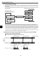
[1] When the I/O message communication time is shorter than the JW-32CUM1
(control section) cycle operation time .................................................................................... 8-34
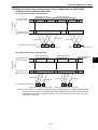
[2] When the I/O message communication time is longer than the JW-32CUM1
(control section) cycle operation time .................................................................................... 8-35
8-6 Error handling ............................................................................................................................ 8-36
8-6-1 Display lamp ......................................................................................................................... 8-36
[1] Error code .............................................................................................................................. 8-37
[2] Display of node addresses .................................................................................................... 8-39
8-6-2 Diagnostic table .................................................................................................................... 8-40
[1] When JW-32CUM1 is master mode ...................................................................................... 8-40
[2] When JW-32CUM1 is used in the slave mode ...................................................................... 8-46
8-7 DeviceNet section communication operation when the control section has stopped
operation or error has occurred ................................................................................................. 8-50
Chapter 9: Remote I/O (Master Station) Function ....................................... 9-1 to 9-19
9-1 Remote I/O (master station) function ...........................................................................................
9-2 Setting method .............................................................................................................................
[1] Setup procedure ......................................................................................................................
[2] Switch settings .........................................................................................................................
[3] Data memory area ...................................................................................................................
[4] I/O registration .........................................................................................................................
[5] Slave station settings ...............................................................................................................
9-3 Required transfer time and its timing ...........................................................................................
[1] Required transfer time .............................................................................................................
[2] PC process and communication timing ...................................................................................
9-1
9-2
9-2
9-3
9-4
9-6
9-7
9-8
9-8
9-8
9-4 Errors and treatment ................................................................................................................... 9-11
[1] Indicators ................................................................................................................................9-11
[2] Operation in error conditions .................................................................................................. 9-12
[3] Error code .............................................................................................................................. 9-14
[4] Check flow ............................................................................................................................. 9-17
Chapter 10: Data link DL1 (Master Station) Function ............................. 10-1 to 10-18
10-1 Data link DL1 (master station) function .................................................................................... 10-1
[1] Communication method of the data link DL1 ......................................................................... 10-2
[2] Communication contents of data link DL1 ............................................................................. 10-3
10-2 Setting method ......................................................................................................................... 10-4
[1] Setup procedure .................................................................................................................... 10-4
[2] Switch settings ....................................................................................................................... 10-5
[3] Data memory area ................................................................................................................. 10-6
10-3 Required transfer time and its timing ....................................................................................... 10-8
[1] Required transfer time ........................................................................................................... 10-8
[2] PC process and communication timing ................................................................................. 10-9
[3] Communicate delay time ......................................................................................................10-11
[4] How to make synchronize .................................................................................................... 10-12
[5] Hierarchy link ....................................................................................................................... 10-13
10-4 Errors and treatment .............................................................................................................. 10-14
[1] Indicators ............................................................................................................................. 10-14
[2] Operation in error conditions ................................................................................................ 10-14
[3] Error code ............................................................................................................................ 10-15
[4] Check flow ........................................................................................................................... 10-17
Chapter 11: Data link DL9 (Master Station) Function ............................. 11-1 to 11-19
11-1 Data link DL9 (master station) function ..................................................................................... 11-1
[1] Communication method of the data link DL9 .......................................................................... 11-2
[2] Communication contents of data link DL9 .............................................................................. 11-3
11-2 Setting method ..........................................................................................................................11-4
[1] Setup procedure ..................................................................................................................... 11-4
[2] Switch settings ........................................................................................................................ 11-5
[3] Data memory area .................................................................................................................. 11-6
11-3 Required transfer time and its timing ......................................................................................11-10
[1] Required transfer time ..........................................................................................................11-10
[2] PC process and communication timing ................................................................................ 11-11
[3] Communicate delay time ......................................................................................................11-12
[4] How to make synchronize .....................................................................................................11-14
[5] Hierarchy link ........................................................................................................................11-15
11-4 Errors and treatment ...............................................................................................................11-16
[1] Indicators ..............................................................................................................................11-16
[2] Operation in error conditions .................................................................................................11-16
[3] Error code .............................................................................................................................11-17
[4] Check flow ............................................................................................................................11-18
Chapter 12: M-net (Master Station) Function .......................................... 12-1 to 12-19
12-1 M-net (master station) function ................................................................................................ 12-1
12-2 Settings .................................................................................................................................... 12-3
12-2-1 How to set (initialize) the M-net system .............................................................................. 12-4
12-2-2 M-net data link area ............................................................................................................ 12-5
12-2-3 Switch settings .................................................................................................................... 12-6
12-2-4 Parameter setting ............................................................................................................... 12-7
12-2-5 Communication program .................................................................................................... 12-8
[1] Program to start communication and select the communication mode ................................. 12-8
[2] Monitoring program for the communication error relay .......................................................... 12-8
12-2-6 Setting example .................................................................................................................. 12-9
[1] System example .................................................................................................................... 12-9
[2] Setting procedure example .................................................................................................. 12-10
12-3 Communication time and communication timing ................................................................... 12-13
12-4 Errors and treatment .............................................................................................................. 12-14
12-4-1 Indicators .......................................................................................................................... 12-14
12-4-2 Error flag ........................................................................................................................... 12-15
[1] Error flag details ................................................................................................................... 12-15
[2] Relationship between communication errors and switch settings ....................................... 12-15
12-4-3 Error code ......................................................................................................................... 12-16
[1] Error code details ................................................................................................................. 12-16
[2] Error code table ................................................................................................................... 12-17
[3] Storing an error code in the system memory ....................................................................... 12-19
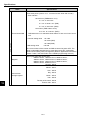
Chapter 13: Specifications .......................................................................... 13-1 to 13-9
13-1 JW30H (JW-32CUM1) general specifications ......................................................................... 13-1
13-2 JW30H (JW-32CUM1) system specifications .......................................................................... 13-2
13-3 JW-32CUM1 performance specifications and communication specifications .......................... 13-3
[1] Performance specification ..................................................................................................... 13-3
[2] Communication specifications ............................................................................................... 13-8
13-4 JW-34KBM ............................................................................................................................... 13-9
13-5 External dimension drawings ................................................................................................... 13-9
Outline
Chapter 1: Outline
The JW-32CUM1 is a control module for the JW30H programmable controller. It has a built in
communication function. Its control section is completely compatible with all JW30H series modules
(equivalent to JW-32CUH1). It occupies two slots (the same as the JW-32CUH1) on a basic rack panel.
Just install it on the proprietary JW-34KBM basic rack panel and the compactly designed JW-32CUM1 will
provide you with communication. By installing a JW-32CUM1, the system does not need a network
module, which saves space and cuts cost.
[1] DeviceNet master function (full time use is possible)
The JW-32CUM1 can connect to slave stations that conform to DeviceNet specifications (common
throughout North America). This is a useful function for common use in facilities both inside and outside
Japan.
- The JW-32CUM1 employs a multi-drop system that can connect between nodes using a single
proprietary cable, significantly reducing electrical wiring labor and material costs. The system also can
contain branches by using a T-branch tap.
- The communication time can be reduced by dividing a system into groups.
- The scan list editing function affords easy I/O allocation of slave stations, so there is no need for a
configurator to make programs.
[2] Select any one of four communication functions with switches
Communication with SHARP programmable controllers is possible by using a twisted-pair cable. Select
any one of four master station functions: Remote I/O, data link DL1/DL9, and M-net.
(1) Remote I/O master station function
Using the JW-32CUM1 as master station, you can configure a remote I/O system as slave station
using I/O modules (such as the slave module JW-21RS) for the JW20H/30H.
(2) Data link DL1 master station function (N: M method)
Making effective use of memory, the JW-32CUM1 provides interlocks between each process step and
a distributed control operation.
(3) Data link DL9 master station function (1: N method)
This function does not support communication between slave stations. Each slave station must
communicate with a master station. Use this function to construct a system with lots of link points and
hierarchic control.
(4) M-net (master station) function
Construct a network with link modules mounted SHARP programmable controllers, other
manufacturers' programmable controllers, measuring instruments, and industrial robots that are Mnet compatible.
[3] Computer link (equipped with 2 ports)
The JW-32CUM1 is equipped with two communication ports for RS-232C and RS-422A communications
(the COMM2 port is for RS-232C use only). Using these ports, the JW-32CUM1 can communicate with a
personal computer or a programmer, etc.
1-1
1
Precautions for Use
Chapter 2: Precautions for Use
When using the JW-32CUM1 (JW-34KBM), pay attention to the following points (1) to (6) that describe
differences from other control modules for the JW30H series (such as the JW-32CUH1).
(1) Installation
The JW-32CUM1 can be installed on a JW-34KBM basic rack panel. It cannot be installed on other
basic rack panels (such as the JW-34KB).
Other control modules, such as JW-32CUH1, cannot be installed on the JW-34KBM basic rack panel.
(2) Allocation of relay numbers
With a JW30H system that is constructed using the JW-32CUM1 (JW-34KBM), the first rack number
0 address must be コ0004 (relay number 00040). Slot numbers for installing I/O, special I/O, I/O link,
and other option modules must start with the number "2."
(3) DeviceNet communications for the JW-32CUM1
- The node address is fixed to "0: Master."
- The data memory area used for the DeviceNet is fixed. (The Module No. switch is fixed to 0.)
(4) General-purpose communications with the JW-32CUM1 (remote I/O, data link DL1/DL9, and
M-net)
- The station number is fixed to "0: Master station."
- The data memory area for general-purpose communications is fixed. (The Module No. switch is fixed
to 0.)
- When using the JW-32CUM1 with remote I/O, a JW-21CM cannot be used as a remote I/O master
station on the same JW-34KBM basic rack panel.
(5) Option modules
Up to four option modules (e.g. the JW-22CM) can be installed on the JW-34KBM (JW-32CUM1). Set
the module No. switch on option modules to some number other than 0.
(The general-purpose communication section of the JW-32CUM1 uses the 0 area.)
(6) I/O link master modules and DeviceNet master modules
- Only one JW-23LMH can be installed on a JW-34KBM (JW-32CUM1). Only operation modes 7 and
8 can be used.
(The DeviceNet section of the JW-32CUM1 uses the areas for operation modes 1 to 6.)
- Up to three JW-20DNs can be installed on the JW-34KBM (JW-32CUM1). Set the module No. switch
to some number other than 0.
(The DeviceNet section of the JW-32CUM1 uses the 0 area.)
The precautions below apply to the JW30H (with a JW-32CUM1) and are the same as for other control
modules (JW-32CUH1 etc.).
(7) Installation
Avoid keeping the JW30H in the following conditions:
- Direct sunlight.
- Relative humidity which exceeds 35 to 90 %. No condensation due to rapid temperature variation.
- Corrosive and flammable gases.
(8) Operation
- Prepare an emergency stop circuit at the external relay circuit, and connect the halt output from the
JW30H. (The halt output is installed in the power supply module.)
- Don't handle switches and connectors excessively by force.
(9) Grounding
Prepare a class-3 grounding of the JW30H separately. Never co-ground with high power equipment
grounding lines.
(10) Installation
- Securely fasten the retaining screws in each module, and confirm again that it is fastened prior to
supply power. Looseness of screws may cause malfunction.
- Firmly connect cable (I/O expansion cable), connecting to the basic/expansion rack panel. Confirm
connectors are fastened prior to supplying power. Looseness may cause malfunction.
- Each module has a ventilation hole to allow for cooling. Do not block the holes.
- Install the JW30H horizontally against a control panel (parallel, wall-mount installation), otherwise
(vertical, wall-mount installation) temperature increase may occur.
(11) Wiring
- Be aware not to cross the connection polarity of 5 VDC on the expansion rack panel. Otherwise,
rack panel and I/O module etc. may be damaged.
- Keep the input/output lines away from high voltage or strong current lines such as power lines.
2-1
2
Precautions for Use
2
(12) Cautions for static electricity
Significant volume of static electricity may build up on the human body in extremely dry conditions.
Prior to touching the JW30H, discharge the static electricity by touching grounded metals.
(13) Cleaning
Use the soft cloths for cleaning. Volatile solvents (alcohol, paint thinner, freon etc.) and wet rags may
cause deformation or change of color.
(14) Storage
Keep the JW30H in cool and dry conditions as it equipped with a battery for memory backup.
High ambient temperature may shorten its battery life.
Do not put other objects on the JW30H.
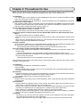
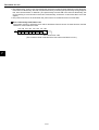
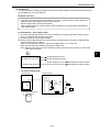
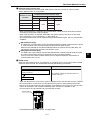
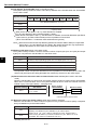
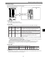
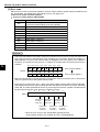
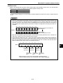
(15) Short circuit protection
If the load connected to the output terminal shorts circuits, the output device or the printed circuit
board may burn. Insert a protective fuse in the output lines.
We recommend that you install protective fuses in each line, even if the external devices have fuses
for each common unit. These common line fuses are to protect the device against burnout caused by
overload, and do not protect against overcurrent of output element and load.
Output module
Precautions when using a rated voltage power
Load
source
Fuse 0
When you use a power supply for loads that have a
1
current limiting circuit, provide fuses that match the
load rating of each output module. If the load is
shorted, and the current limiting circuit functions, the
COM
short-circuit current will flow at current level lower than
needed to blow the fuse.
Power supply load
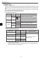
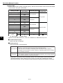
(16) Insulation transformer
Choose isolation transformer with a capacity 20% or more higher than the rated load. When a
transformer of the same capacity as that of the rated load is used, the primary input voltage might
exceed the rated transformer capacity.
Power supply
module
Power
consumption*
Transformer
capacity
60 VA or less
72 VA or more
70 VA or less
85 VA or more
JW-21PU
JW-22PU
* Maximum load capacity when one
power supply module is used.
JW-31PU
JW-33PU
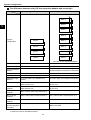
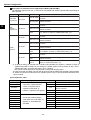
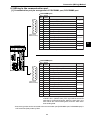
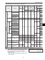
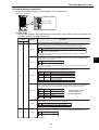
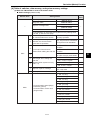
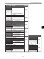
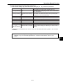
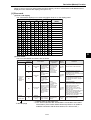
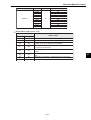
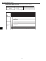
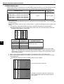
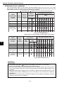
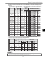
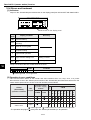
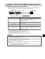
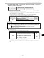
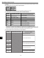
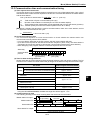
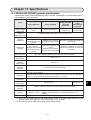
(17) Max. No. of I/O points
Each control module has a maximum number of input and output points, but the number of relay
points affecting the maximum number of input and output points varies with the type of the module. It
must be noted that it is different from the number of relay assignments.
Allocation
The number of relay points
No. of
affecting the maximum number
points
of I/O points
Kinds of module
8 points input/output
16
16
16 points input/output
16
16
32 points input/output / I/O
32
32
Special I/O (64 points input/output)
16
64
Special I/O (except for 64 points input/output)
16
0
Option
16
0
I/O link, DeviceNet
16
0
Vacant slot
16
0
Max No. of
I/O points
1024 points
In case of all 16
points module
In case of all 32
points module
In case of all 64
points module
16 points x 60 sets =
960 points
32 points x 32 sets =
1024 points
64 points x 16 sets =
1024 points
2-2
Precautions for Use
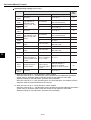
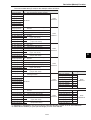
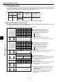
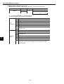
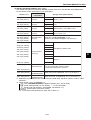
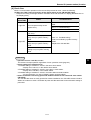
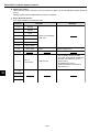
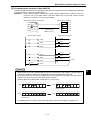
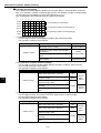
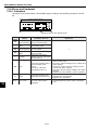
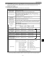
(18) Notes for using communication module, support tool
When you use a JW30H communication module or support tool, check the version you are using
carefully. Depending on the version, some limitation on the use may be involved, or it may not be
possible to use it.
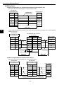
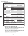
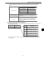
1. Communication modules
The following communication modules may be compatible with or not compatible at all with
JW30H depending on their version.
Modules mounted on the JW30H:
JW-21CM, JW-22CM, JW-21MN, JW-23LM, and
JW-23LMH
Modules communicating with JW30H: JW-20CM, JW-20RS, JW-20MN, ZW-98CM, ZW20AX, JW-98MN, JW-90MN, Z-313J, Z-331J, Z332J, Z-333J, Z-334J, Z-335J
1 A "30Hn" mark is put on modules which are compatible with the JW30H control modules
JW-32CUM1 and JW-31CUH1/32CUH1/33CUH1/33CUH2/33CUH3 (current models).
2 A "30H" mark is put on modules which are compatible with the JW30H control modules,
including JW-31CUH/32CUH/33CUH (conventional models).
3 Neither the "30Hn" nor "30H" mark is put on a module that is not compatible with the
JW30H. (Compatible with the JW20H only.)
-In case of JW-21CM
30H
30Hn
With "30Hn" mark
With "30Hn" mark
Without any mark
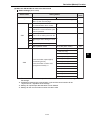
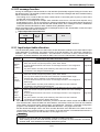
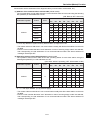
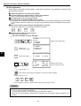
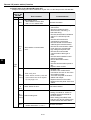
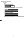
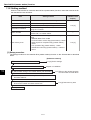
After installing a JW-32CUM1, the range of use for the JW30H shall be as follows.
Compatibility of modules
mounted on the JW30H
Communication with the JW30H
1 With "30Hn" mark
All functions available with all Available communication with all
JW30H (JW-32CUM1) models the JW30H (JW-32CUM1) modules.
2 With "30H" mark
Communication available taking for
Available within the functional granted that the current JW30H
range of conventional JW30H (JW-32CUM1) modules function in
modules
the same way as a conventional
JW30H module.
Without "30Hn" or
3 "30H" marks
All functions are unavailable
when mounded in the JW30H
(JW-32CUM1) modules (They
do not function)
Communication available taking for
granted that the JW30H (JW32CUM1) modules function in the
same way as a conventional
JW20H or either of
JW50H/70H/100H module. *
*: A decision taking for granted that a JW30H (JW-32CUM1) as whether a JW20H or either of
JW50H/70H/100H is subject to the settings of JW30H system memory #260. (# 260 =
50HEX: JW50H/70H/100H, and other than #260 = 50HEX: JW20H)
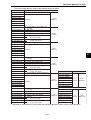
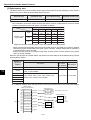
2. Support tool
The following support tools may be compatible with or not compatible at all with JW30H (JW32CUM1) depending on their versions.
- Hand-held programmer: JW-13PG
- Multi-purpose programmer: JW-50PG
- Ladder software: JW-50SP
See page 7-30 in details about support tool.
2-3
2
Precautions for Use
2
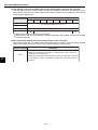
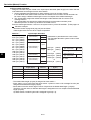
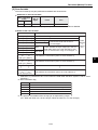
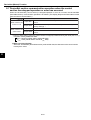
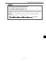
(19) Special I/O modules
If a preset scanning time is too short ( less than 2 ms), the special I/O module such as JW-21SU may
not function normally.
To avoid this malfunction, set a longer scanning time using a constant scanning (set 3 ms or more on
the system memory #226) or other functions.
(20) Insulation resistance and dielectric strength tests of the power supply module
When testing insulation resistance or dielectric strength of the JW-21PU/31PU power supply
modules, be sure to remove the short bar connected between the SHORT terminal and the GND
terminal. If a test is carried out without removing the short bar, internal elements of the module may
be damaged.
2-4
System Configuration
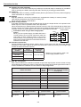
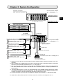
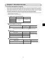
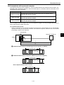
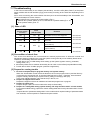
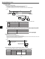
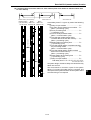
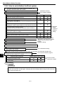
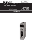
Chapter 3: System Configuration
*5
I/O bus expansion adapter
(JW-32EA)
Expansion rack panel
(Max. amount of connection: 7)
Termination connector
(Attached to JW-31EA)
3
I/O, special I/O module *2
I/O expansion cable
(Total length: max. 50 m)
DeviceNet
Slave = Max. 63 nodes
Communication
Communication
speed
distance
125k bps
Max. 500 m
250k bps
Max. 250 m
500k bps
Max. 100 m
- Chapter
8
Power supply module
JW-32CUM1
JW-34KBM
(Basic rack panel)
FLT
CM1
CM2
DN-M
CM-M
OFF
SCAN
LT
CU
PROTECT
ON
ON
OFF
PULL
Data link DL1 (N: M system)
Transmission speed = 153.6 kbps
- Chapter
Slave station = Max. 15 sets
10
Shielded twisted pair cable = Max. 1 km
Data link DL9 (1: N system)
Transmission speed = 153.6 kbps
- Chapter
Slave station = Max. 15 sets
11
Shielded twisted pair cable = Max. 1 km
This
battery
expires
L1
L2
*5
I/O bus expansion adapter
(JW-31EA)
PG/COMM1
Exchange
the battery
within
5 minutes.
SHLD
FG
PG/COMM2
I/O, special I/O, I/O link,
option module *2
*1
Remote I/O
Transmission speed = 307.2 kbps
- Chapter
Slave station = Max. 4 sets
9
Shielded twisted pair cable = Max. 500 m
Support tool
Programmer JW-14PG etc.
M-net
Transmission speed = 19.2 kbps/38.4 kbps *3
- Chapter
Slave station = Max. 7 sets
12
Shielded twisted pair cable = Max. 1 km *4
Computer link
[Transmission speed = Max. 115.2kbps] -7-4
Personal computer,
LCD Control Terminal etc.
*1: Select any one of the four communication functions (master station) using the switches on the JW32CUM1.
*2: All the modules in the JW30H series, such as I/O, special I/O, I/O link, and option module, can be used
like other control modules (JW-33CUH1 etc.). => See page 3-4.
*3: The transfer speed of 38.4 kbps is a unique function of SHARP modules. When connecting modules
from other manufacturers, use the JW-32CUM1 set to a transfer speed of 19.2 kbps (standard M-net
specification).
*4: The total cable length of 1 km is only supported when using SHARP modules exclusively. When
connecting modules from other manufacturers, use the shortest total cable length specified for the
modules connected. The total cable length specified for the M-net is 100 m.
*5: A system that does not use an I/O bus expansion adapter is also possible. => See the next page.
For details about DeviceNet, data link DL1/DL9, remote I/O, and M-net, see Chapters 8 to 12.
3-1
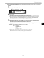
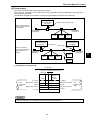
System Configuration
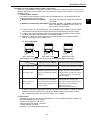
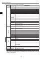
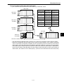
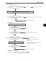
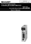
The difference between using I/O bus expansion adapter and not using it
When not using I/O bus expansion adapter
When using I/O bus expansion adapter
JW-32EA I/O bus expansion adapter
Rack 7
32
E
A
Rack 6
32
E
A
Rack 5
32
E
A
Rack 4
32
E
A
Rack 3
Rack 3
32
E
A
Rack 2
Rack 2
32
E
A
Rack 1
Rack 1
32
E
A
Rack 0
Rack 0
31
E
A
3
System
configuration
JW-31EA I/O bus expansion adapter
Basic rack panel
JW-34KBM
JW-34KBM
Expansion rack panel JW-34ZB/36ZB/38ZB
JW-34ZB/36ZB/38ZB
I/O bus expansion
adapter
JW-31EA (Install in basic rack panel)
JW-32EA (Install in all expansion rack panel)
_
I/O expansion cable JW-203EC/207EC/22EC/25EC/210EC
JW-05EC/1EC/3EC/10EC/20EC/30EC/50EC
No. of racks
4 racks max.
8 racks max.
Cable total length
distance
14 m max. (Max. 10 m between rack
panels)
50 m max. (Max. 50 m between rack panels)
No. of I/O modules
Max. 28 sets for basic/expansion rack
panel (racks 0 to 3)
Max. 60 sets for basic/expansion rack panel
(racks 0 to 7)
No. of special I/O
modules
Max. 28 sets for basic/expansion rack
panel (racks 0 to 3)
Max. 28 sets for basic/expansion rack panel
(racks 0 to 3)
No. of option
modules
Max. 4 sets for basic rack panel (rack 0)
Max. 4 sets for basic rack panel (rack 0)
No. of I/O link
modules
Max. 1 sets for basic rack panel (rack 0) *1
Max. 1 sets for basic rack panel (rack 0) *1
No. of DeviceNet
modules
Max. 3 sets for basic rack panel (rack 0) *2
Max. 3 sets for basic rack panel (rack 0) *2
Connection support Unavailable
tool with expansion
rack panel
Available for connected I/O bus expansion
adapter JW-32EA
*1: Maximum of one JW-23LMH module (operation modes 7/8 only).
*2: Maximum of three JW-20DN modules.
3-2
System Configuration
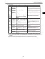
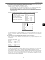
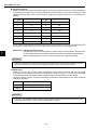
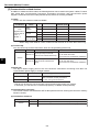
(1) Control module
Model name
No. of In/Out
JW-32CUM1
1024 points
Program size
File register
15.5K words
80K bytes
31.5K words
48K bytes
Clock feature,
communication port
Yes
Set program capacity and file register capacity of the JW-32CUM1 using the internal switch (SW2) of
the module.
3
(2) Power supply module
Approved
UL/CSA
Model name
Specification
JW-21PU
85 to 264 VAC. Power capacity: 5 VDC 3.5 A
JW-22PU
20.4 to 32 VAC. Power capacity: 5 VDC 3.5 A
JW-31PU
85 to 132 VAC. Power capacity: 5 VDC 3.5 A
O
JW-33PU
85 to 264 VAC. Power capacity: 5 VDC 4.5 A
O
Approved CE
O
(3) Basic rack panel
No. of slots
Model name
For power
supply module
For control
module
For I/O
module
1
1
4
JW-34KBM
I/O bus expansion
adapter (Installation of
JW-31EA)
Available
The slot for I/O module is a slot mounting I/O, special I/O, I/O link, and option module.
(4) Expansion rack panel
No. of slots
Model name
For power
supply module
For I/O
module
JW-34ZB
1
4
JW-36ZB
1
6
JW-38ZB
1
8
I/O bus expansion adapter
(Installation of
JW-32EA)
Available
The slot for I/O module is a slot mounting I/O, special I/O module.
(5) I/O bus expansion adapter
Model name
Specifications
JW-31EA
Mounting to basic rack panel (JW-34KB/36KB/38KB)
JW-32EA
Mounting to expansion rack panel (JW-34ZB/36ZB/38ZB), with PG port
Use an I/O bus expansion adapter when more than 5 racks (max. 8 racks) on the rack panel are used,
or when total length of I/O expansion cables is longer than 15 meters (max. 50 meters).
3-3
System Configuration
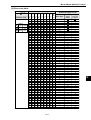
(6) I/O, special I/O, option, I/O link, DeviceNet module
Model
name
Specifications
JW-201N
8 points input, 100/120 VAC
JW-202N
8 points input, 12/24 VDC
JW-203N
8 points input, 200/240 VAC
JW-211NA 16 points input, 100/120 VAC
JW-212NA 16 points input, 12/24 VDC
3
JW-214NA 16 points input, 12/24 VDC (high speed type)
I/O
JW-234N
32 points input, 12/24 VDC (high speed type, connector connection)
JW-202S
8 points output, 5/12/24 VDC, 1A, transistor output (sink output)
JW-203S
8 points output, 100/200 VAC, 1A, triac output
JW-204S
8 points output, 250 VAC/30 VDC, 2A, relay output (separated
common)
JW-212SA 16 points output, 5/12/24 VDC, 0.5A, transistor output (sink output)
JW-213SA 16 points output, 100/200 VAC, 1A triac output
Special I/O
JW-214SA 16 points output, 250 VAC/30 VDC, 2A, relay output
Option
*
JW-232S
32 points output, 5/12/24 VDC, 0.1A, transistor output (sink output,
connector connection)
JW-232M
16 points input, 12/24 VDC
16 points output, 5/12/24 VDC, 0.1A, transistor output (sink output,
connector connection)
JW-264N
64 points input, 24 VDC (high speed type, connector connection)
JW-262S
64 points output, 5/12/24 VDC, 0.1A, transistor output (sink output,
connector connection)
JW-21HC
High speed counter: 100 kHz 1ch
JW-22HC
High speed counter: 100 kHz/200 kHz 2ch
JW-24AD
Analog input: 4 points 13 bits
JW-22DA
Analog output: 2 points 16 bits
JW-22DU
ID control: Microwave system
JW-21SU
Serial interface 1ch RS-232C/422A
JW-21PS
Pulse output, number of control axis: 1. Max speed: 250 kpps.
JW-21CM
Select from computer link / data link / remote I/O functions by
switching.
JW-22CM
Net work module
JW-21MN
ME-NET module
JW-25CM
JW10 link module
JW-255CM Ethernet module
JW-20FL5
JW-20FLT
*
I/O link
DeviceNet
FL-net module
JW-23LMH
I/O link master station, up to 32 slave stations, max. 504 points, 345.6
kbits/s / 172.8 kbits/s
JW-20DN
DeviceNet master module
JW-21RS
Remote I/O slave module
*: Make sure to use the JW30H series applicable products for the JW-23LMH, JW-21CM, JW-22CM,
and JW-21MN. Items applicable with the JW30H series are stuck [30Hn] mark in front of the
modules. => See page 2-3.
3-4
System Configuration
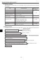
(7) Support tools
Model name
Outline
Ladder
processor II
Multi-purpose
programmer
Hand-held
programmer
JW-14PG
----------See the table in the next page for
versions
JW-13PG
LCD dot matrix display
JW-12PG
Usable within the functions of the
JW20H or JW50H/70H/100H.*2
JW-2PG*1
Usable within the functions of the
JW20H.*2
LCD display (640 x 480 dot)
Built-in 1 set of 3.5" floppy disk
JW-50PG drive
Built-in 1 set of 2.5" hard disk
(256MB)
See the table in the next page for
versions.
Z-100LP2S
+
Z-3LP2ES
(Expansion
module)
JW-92SP
Ladder software
Remarks
EL display
Horizontal: 11 relay contacts plus
1 coil
Vertical: 11 relay lines plus 2
message lines
Built in 1 set of 3.5" floppy disk
drive.
Usable within the functions of the
JW20H or JW50H/70H/100H when
Z-3LP2ES is installed. (Ver 5.2 or
more)
Ladder software for PC-98
series, Japanese display
See the table in the next page for
versions
Ladder software for DOS/V
JW-52SP personal computer, Japanese
display
See the table in the next page for
JW30H applied versions.
JW-50SP Ladder software for IBM-PC
See the table in the next page for
JW30H applied versions.
JW-100SP
Ladder logic programming
software
-----------
*1 When JW-2PG is used by JW30H, be sure to set 02HEX on the system memory #136 of JW30H.
*2: Forced set/reset, data transfer using a ROM writer, and data transfer using cassette tapes are not
available.
Note: Do not connect to the programmer ZW-101PG1, or malfunction may be caused.
3-5
3
System Configuration
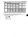
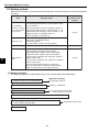
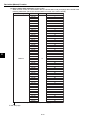
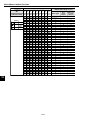
Description of software version approved to JW30H (JW-32CUM1)
The following support tools may, or may not be compatible with JW30H (JW-32CUM1) depending on
their versions.
Items
Model names
Hand-held
programmer JW-13PG
3
Versions
Available functions when used with JW30H
All functions are available with all JW30H (JW-32CUM1)
With "B" mark modules.
With "A", or
Usable within the function range of the conventional
without marks JW30H modules.
Ver5.5 or later All functions are available with all JW30H (JW-32CUM1)
modules
Multipurpose
JW-50PG
programmer
Ver5.0 to 5.3A Usable within the functional range of the conventional
JW30H modules
Ver4.0A or
earlier
JW-52SP
Usable but it operates taking for granted that the JW30H
is a JW20H, or either of JW50H/70H/100H. (*3)
All functions are available with all JW30H (JW-32CUM1)
Ver5.5 or later modules
within the functional range of the conventional
Ver5.0 to 5.3A Usable
JW30H modules.
All functions are available with all JW30H (JW-32CUM1)
Ver5.5 or later modules.
Ladder
software
JW-92SP
JW-50SP
with the functional range of the conventional
Ver5.0 to 5.3A Usable
JW30H modules.
Ver4.0A or
earlier
Usable but it operates taking for granted that the JW30H
as a JW20H, or either of JW50H/70H/100H. (*3)
Ver5.5I or
later
All functions are available with all JW30H (JW-32CUM1)
modules
Ver5.0I to
5.3AI
Usable with the functional range of the conventional
JW30H modules.
Ver3.0I
Usable taking for granted that the JW30H as a JW20H, or
either of JW50H/70H/100H. (*3)
*3: A decision taking for granted that a JW30H (JW-32CUM1) as whether a JW20H or either of
JW50H/70H/100H is subject to the settings of JW30H system memory #260. (# 260 = 50HEX:
JW50H/70H/100H, and other than #260 = 50HEX: JW20H)
This version cannot perform forced set/reset of relays and sampling trace.
- The JW-14PG and JW-100SP can use their all functions with all JW30H (JW-32CUM1) series models.
- A JW30H conventional model refers the JW30H system using a JW-31CUH/32CUH/33CUH as a
control module.
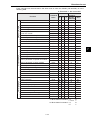
(8) I/O expansion cable
Model name
JW-203EC
JW-207EC
JW-22EC
JW-25EC
JW-210EC
JW-05EC
JW-1EC
JW-3EC
JW-10EC
JW-20EC
JW-30EC
JW-50EC
Specifications
Connection cables between
a basic rack panel and an
expansion rack panel, or
between expansion rack panels.
Connection cables between
a JW-31EA and a JW-32EA, or
between a JW-32EA and a
JW-32EA.
3-6
30 cm
70 cm
2m
5m
10 m
50 cm
1m
3m
10 m
20 m
30 m
50 m
Accessories
5 V DC cable (30 cm)
5 V DC cable (70 cm)
5 V DC cable (2 m)
Short connector
Short connector
Short connector
5 V DC cable (50 cm)
5 V DC cable (1 m)
None
None
None
None
None
System Configuration
(9) PG connection cable
Specifications
Model name
JW-22KC
Connection cable between a support tool and the JW30H. 2 m
JW-24KC
Connection cable between a support tool and the JW30H. 4 m *
* JW-24KC cannot be used with JW-2PG.
3
3-7
Name and Function of each part
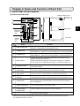
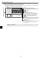
Chapter 4: Name and Function of Each Part
4-1 JW-32CUM1 (Control module)
[1] Front view, side view
Module retention screw
JW-32CUM1
FLT
4
CM1
CM2
DN-M
8
9
CM-M
OFF
SCAN
CU
PROTECT
ON
Up side : 2
Low side : 1
1
2
3
5
ON
OFF
LT
130
6
0
PULL
Battery life
indication
label
PG/COMM1
L1
7
L2
q
Rating plate
SHLD
FG
(Unit: mm)
Software
version
label
PG/COMM2
70.5
w
109.4
Name
Function
1
FAULT lamp (red)
Lights when detecting errors by self-diagnosis. PC stops its operations.
(However, it operates even when battery is error.)
2
COMM1 lamp
Lights when communicating with personal computer or the like, by using
PG/COMM1 port. Lights up in monitoring state by connecting support tool.
3
COMM2 lamp
Lights when communicating with personal computer or the like, by using
PG/COMM2 port. Lights up in monitoring state by connecting support tool.
Displays the operating status of the DeviceNet communications, and
general-purpose communications*.
4
Display panel
5
PROTECT switch
Set prohibit (ON), enable (OFF) about writing to program memory
and system memory.
6
PG/COMM1 port
(with cover)
A connector for connecting with support tool. A connector for connecting
with device having serial I/O port such as personal computer.
7
PG/COMM2 port
(with cover)
A connector for connecting with device having serial I/O port such as
personal computer. (Also possible to connect with support tool.)
8
Termination resistance Specifies whether this module is a termination station (ON) or an
switch LT
intermediate station (OFF) in the general-purpose communication circuit*.
9
SCAN switch
With the DeviceNet function, keep pressing this switch longer than three
seconds and operate "Reloading switch and system memory settings,
etc." -Page 8-11.
0
DeviceNet
communication port
Connect a DeviceNet communication cable.
q
General-purpose
communication
terminal block
Connect cables for general-purpose communications*.
w
Battery cover
A battery module for memory backup is provided inside; opened and
closed when replacing battery.
Details: DeviceNet - Page 8-27, Remote I/O - Page 9-11, Data link
DL1 - Page 10-14, Data link DL9 - Page 11-16, M-net - Page 12-14.
* Select one of the four master station functions for general-purpose communications: Remote
I/O, data link DL1/DL9, or M-net.
4-1
4
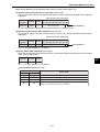
Name and Function of each part
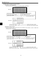
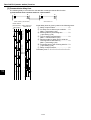
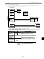
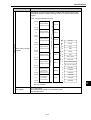
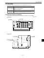
[2] Rear view
OFF side ON side
01
EF
01
CD
AB
EF
01
EF
01
EF
01
EF
ABCD
ABCD
SW8
CD
AB
Switch SW2
]
(1)
2345
8
67 9
8
67 9
CD
AB
01
ABCD
EF
Switch SW7
Switch SW8
]
(2)
8
67 9
2345
SW5
4
1 2 3 4 5 6 7 8
8
67 9
8
67 9
4
23 5
2345
SW4
8
67 9
4
23 5
1 2 3 4 5 6
SW3
12345678
123456
4
23 5
Switch SW3
Switch SW4
Switch SW5
]
(3)
7
SW
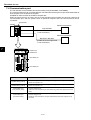
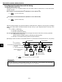
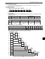
(1) Switch SW2
Set the program capacity and register capacity of file 2.
SW2
Program capacity
File 2 capacity
31.5K words
32K bytes
15.5K words
64K bytes
Set at delivery
Note: Changing settings of the SW2 will erase program contents that have been set before the
change, as well as a part of file 2 data. We recommend that you back-up programs and data
by using a support tool, such as the JW-100SP, as you may need to use the same data after
the change. After setting changes of the SW2 are completed, be sure to initialize all memory
using a support tool such as the JW-14PG.
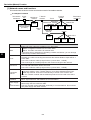
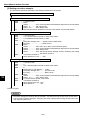
(2) Switch SW7, 8
These switches are used to specify the DeviceNet communication details. Details - Page 8, 9 to 10
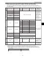
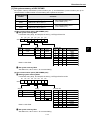
(3) Switch SW3 to 5
Use these switches to specify the details for general-purpose communications (remote I/O, data link
DL1/DL9, and M-net).
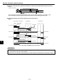
Switch SW5
Switch SW3
Remote I/O
1
Operating mode
Data link DL1
2
Mode 0 Mode 1 Mode 2
3
4
5
6
OFF
OFF
OFF
OFF
ON
OFF
OFF
OFF
OFF
ON
OFF
OFF
Number of slave
Switch SW4 stations connected
1 to 4
Normal OFF
Normal OFF
Normal OFF
Normal OFF
Data link DL9
3
Total number
of bytes
64
128
256
OFF
OFF
OFF
OFF
ON
OFF
OFF
OFF
OFF
ON
OFF
OFF
M-net
7
Operating mode
All stations Error stations
stop
stop
OFF
OFF
OFF
ON
OFF
OFF
OFF
OFF
Number of slave stations connected
1 to 9, A: 10, B: 11
C: 12, D: 13, E: 14, F: 15
- Switches SW3-1 and 3-2 are not used. (Set to ON as the default setting.)
- Switches SW3-3 to 3-6 are set to OFF when delivered.
- Switches SW4 and SW5 are set to "0" when delivered.
For details about the settings, see "Switch settings" in Chapters 9 to 12.
4-2
Transfer speed
0: 19.2kbps
7: 38.4kbps
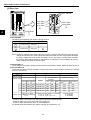
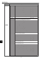
Name and Function of each part
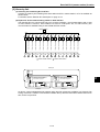
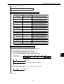
4-2 JW-34KBM (Basic rack panel)
The JW-34KBM shall be used as a basic rack panel when the JW-32CUM1 is used as a control module.
Module retention screw
φ6
1
3
5
7.6
8
2
(Unit: mm)
CU
PU
SL0T0 SL0T1
SL0T2
SL0T3
SL0T4
SL0T5
EX-CN(OUT)
6
118
130
4
4
4
281
297
8
10.2
8
R3
4
7
6
Name
Function
1
Control module slot
(CU, SLOT 0/1)
2
Power supply module slot (PU) Install a power supply module here.
3
I/O module slot (SLOT2 to 5)
Install I/O, special I/O, I/O link, or option modules.
- Slot numbers: 2 to 5.
4
I/O extension connector
(EX-CN (OUT))
Connect an I/O extension cable or a JW-31EA I/O bus
extension adapter.
5
Mounting holes (4 positions)
Install the JW-34KBM on a control panel wall. (Minimum wall
thickness: 1.6 mm)
6
5 V (FG)
terminal block
7
5 VDC (+, -)
FG
Module fixing rib insert hole
Install the JW-32CUM1 here.
Connect this block to the next expansion rack panel and
supply 5 VDC.
Connect a class 3 or better ground.
Insert the module fixing ribs here when installing a power
supply, I/O, special I/O, I/O link, or option module.
4-3
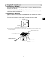
Installation
Chapter 5: Installation
[1] Installation of the JW-34KBM
Drill M5 tapped installation holes on the control panel wall and secure the JW-34KBM basic rack panel to
the panel wall using M5 screws.
- For installation dimension details regarding the JW-34KBM, see Section 4-2.
- Allow 50 to 150 mm distance between each rack panel. Allow 50 mm or more between the left and right
walls, or a wiring duct. Allow 30 mm or more between a wiring duct above or below the basic and
expansion rack panels. => See Section 6-4.
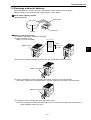
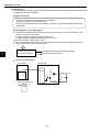
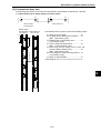
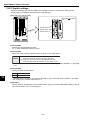
[2] Installation of the JW-32CUM1
Install the JW-32CUM1 control module at the JW34KBM basic rack panel (the power supply module on
the right.)
1 Set the switches on the back of the JW-32CUM1 (SW2 to 5, 7, and 8).
For details, see "Switch settings" in Chapters 8 to 12.
2 Insert the connector on the JW-32CUM1 into the control module slot on the JW-34KBM.
Control panel
JW-34KBM
Module inserting guide
JW-32CUM1
Module retention rib
Inserting hole of module retention rib
3 Screw in the module securing screws (2 at the top and 1 at the bottom) for the JW-32CUM1, using
a Philips screwdriver.
Module retention screw
Power supply module
Phillips screwdriver
JW-34KBM
JW-32CUM1
5-1
5
Connection (Wiring) Method
Chapter 6: Connection (Wiring) Method
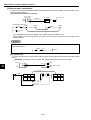
6-1 Connection to a DeviceNet communication connector
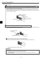
[1] Preparing a communication cable
Below describes how to install a connector to the DeviceNet communication cable.
Prepare the communication cable by following the steps below to attach the connector.
1 Remove approximately 30 mm of insulation from the communication cable
- Remove the insulation without damaging the coaxial shield around the cable.
Do not remove more insulation than necessary, as it may cause a short-circuit.
Communication cable
Approximately
30 mm
2 Unwrap the wires in the coaxial shield carefully
- Under the coaxial shield there is one signal line, one power line, and one ground line. The signal line
and power lines are wrapped in aluminum tape.
Aluminum tape
Ground line
3 Cut off the excess coaxial shield and peel back the aluminum tape on the signal line and power line.
4 Remove the insulation from the signal and power lines until enough bare wire is exposed to fit into a
crimp-style terminal.
- Twist the strands of wire in the signal and power lines tightly, in order to slide them into a terminal.
The length needed to fit into a crimp-style terminal.
5 Crimp a terminal on each of the individual lines and then insulate it using vinyl tape or shrink tubing.
Cable
Crimp-style terminal
- Shown below are the recommended crimp-style terminals
Recommended crimp-style terminals
AI series made by Phoenix Contact
Special tool
ZA3 made by Phoenix Contact
TC series made by Nichifu
- For thin wire : TME TC-0.5
NH-32
- For thick wire : TME TC-2-11 (power line)
TME TC-1.25-11 (communication line)
To the next page
6-1
6
Connection (Wiring) Method
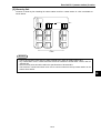
From the previous page
6 Insert the signal line, power line, and the ground line into the appropriate connector holes.
- Insert the wires from the top down, in the following order: red, white, ground , blue, and black.
Pay strict attention to the connector orientation.
- Before inserting the wires, loosen the screws on the connector enough to insert the wires easily.
- The JW-32CUM1 is supplied with one set of MSTB2.5/5-STF-5.08AU (With a screw to secure the
connector: Phoenix Contact).
Connector (mounting)
Red (V+)
White (CAN H)
Ground
Communication cable
Blue (CAN L)
Black (V —)
6
7 Secure each wire tightly using the wire retention screws of the connector.
- Use a miniature flat blade screwdriver which has the same diameter from the neck all the way to the
end. Tighten the screws using 0.5 N-m of force.
Miniature flat blade
screwdriver
Cable securing screw
When connecting two thin cables in a multi-drop system
Insert the wires from each cable with the same color insulation into the same hole.
- Crimp a terminal to the tip of the two wires.
Remarks
- Before connecting the communication cable, make sure to turn OFF the power to the JW30H,
all slave stations, and the communication power supply.
- Do not pull hard on the communication cable since the connector can be pulled off or
disconnected easily.
6-2
Connection (Wiring) Method
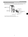
[2] Connecting a communication cable
Match the orientation of the connector on the communication cable (DeviceNet) with the DeviceNet
communication connector on the JW-32CUM1 and insert as far as it will go. After inserting it all the way,
tighten the screws on the connector. The appropriate tightening torque is 0.3 N-m of force.
MS
DeviceNet communication
connector
NS
SDRD FT PT
S3 S2 S1 S0
S7 S6 S5 S4
DN-M
SCAN
Screw (2 positions)
Red (V+)
White (CAN H)
Shield
Communication cable
(DeviceNet)
JW-32CUM1
6
Blue (CAN L)
* Cable connector
Black (V —)
* One male connector is supplied with the JW-32CUM1.
- Model name: MSTB2.5/5-STF-5.08AU (made by Phoenix Contact)
6-3
Connection (Wiring) Method
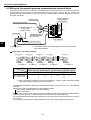
6-2 Wiring to the general-purpose communication terminal block
Connect the communication cable for general-purpose communications to the general-purpose
communication terminal block on the JW-32CUM1, as shown below, using a two-wire system. For
general-purpose communications, select one of the four master station functions: Remote I/O, data link
DL1/DL9, and M-net.
General-purpose
communication
terminal block
Insulation tape
Communication cable
(general-purpose communications)
L1
L2
To the GND terminal
on the power
supply module
*1
SHIELD
FG
JW-34KBM
Twisted-pair wire
(30 mm max.)
JW-32CUM1
Ground line (200 mm max.)
6
*1: The SHIELD terminal and FG (frame ground) are connected to
each other internally.
Class 3 ground
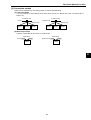
Slave station connection diagram
Master station
00
L1
L2
SHIELD
FG
Slave station
01
L1
L2
SHIELD
FG
Class 3 ground
Total length of cable
Max. number of
slave stations that
can be connected
Slave station
02
L1
L2
SHIELD
FG
Class 3 ground
Slave station
03
L1
L2
SHIELD
FG
Class 3 ground
Slave station
n
L1
L2
SHIELD
FG
Class 3 ground
Class 3 ground
Remote I/O
master station
Data link DL1
master station
Data link DL9
master station
M-net
master station
500 m max.
1 km max.
1 km max.
1 km max. *2
4
15
15
7
*2: When connecting modules from other manufacturers, create a system within the shortest
total cable length specified by any of the modules.
- Use shielded, twisted-pair cable as the communication cable you connect to the L1, L2, and SHIELD
terminals.
- Make sure to use one of the following communication cables.
Hitachi Cable: S-IREV-SW2*0.5, S-IREV-SB2*0.5
Fujikura: RG-22B/U
- Make sure to provide a class 3 ground for the FG (GND) terminals of the master and slave stations.
Without a class 3 ground, a communication error may occur due to electrical nose.
- Connect separate wires between each terminal. Do not use one wire for two or more lines, or for links
to one point.
- Do not lay the communication cables parallel to or too close to high voltage or power lines.
6-4
Connection (Wiring) Method
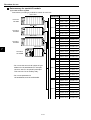
6-3 Wiring to the communication port
[1] Communication port pin arrangement of PG/COMM1 port, PG/COMM2 port
PG/COMM1 port
Pin
No.
Signal
name
1
FG
Outside body grounding
2
—
*1
3
SD(+)
15 14 13 12 11 10 9
8
7
6
5
4
3
2
1
Contents
(15 pin D-sub
female connector)
JW-32CUM1
FLT
CM1
4
—
5
RTS(– )
Sending data (PC to personal computer)
*1
6
SG
Signal grounding
SG
Signal grounding
—
*1
---
RD(+) Receiving data (Personal computer to PC)
10
RD(– ) Receiving data (Personal computer to PC)
11
SD(– ) Sending data (PC to personal computer)
—
13
RTS(+)
14
+5 V
15
+5 V
RS-422A
---
9
12
---
RS-422A
7
8
Signal
*1
RS-422A
--RS-422A
---
CM2
DN-M
CM-M
OFF
SCAN
LT
*1: Not connected with pin No. 2, 4, 8, and 12.
CU
PROTECT
ON
ON
OFF
PULL
PG/COMM2 port
PG/COMM1
L1
L2
Signal
name
1
FG
Outside body grounding
2
SD
Sending data (PC to personal computer)
Contents
Signal
—
2
FG
8
7
6
5
4
3
PG/COMM2
15 14 13 12 11 10 9
1
SHLD
Pin
No.
(15 pin D-sub
female connector)
3
SD(+)
4
RD
5
RTS(– )
6
SG
Signal grounding
7
SG
Signal grounding
8
RTS
ON while PC is supplied power source *2
Sending data (PC to personal computer)
RS-422A
Receiving data (Personal computer to PC)
RS-232C
RS-422A
9
RD(+) Receiving data (Personal computer to PC)
10
RD(– ) Receiving data (Personal computer to PC)
11
SD(– ) Sending data (PC to personal computer)
12
CTS
13
RTS(+)
14
+5 V
15
+5 V
RS-232C
ON: Available sending, OFF: Ban sending
—
RS-232C
RS-422A
RS-232C
RS-422A
---
*2: When system memory #222 in the JW-32CUM1 control
module is 00HEX (default value), RTS signal will be turned ON
while the PC is turned ON power. When it is set to 02HEX, the
RTS will be OFF while sending data, and OFF while other
than sending data.
- Connector type that can be connected to the communication port (PG/COMM1 port, PG/COMM2 port) is
17JE-23150-02 (D8A) made by DDK.
6-5
6
Connection (Wiring) Method
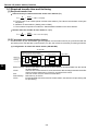
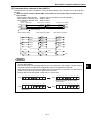
[2] Wiring figure
(1) When using RS-232C for communication method of host computer side.
Be within 15m for the total length of a communication cable.
JW-32CUM1
(PG/COMM2 port)
Host computer
Shielded wire
Pin No.
Signal name
Signal name
1
FG
FG
2
SD
RD
4
RD
TD
8
RTS
CS
12
CTS
RS
7
SG
SG
Within 15m
RS-232C
6
Use the RS-232C/RS-422 converter, such as Z-101HE, when the total length of the communication
cable is over 15m.
JW-32CUM1
PG/COMM1 port
or PG/COMM2 port
RS-232C/RS-422 converter
(Z-101HE)
Host computer
Pin No.
Signal name
Terminal block
name
3
SD (+)
RD (+)
3
RD
RD
11
SD (-)
RD (-)
2
TD
TD
9
RD (+)
TD (+)
4
RS
RS
10
RD (-)
TD (-)
7
SG
SG
1
FG
SHIELD
1
FG
FG
Pin No.
Signal name
Signal name
Shielded wire
Shielded wire
Class-3 grounding
Within 1km
RS-422A
Within 15m
RS-232C
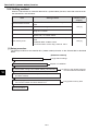
(2) When using RS-422A for communication method.
Be within 1km for the total length of a communication cable.
JW-32CUM1
PG/COMM1 port
or PG/COMM2 port
JW-32CUM1
PG/COMM1 port
or PG/COMM2 port
Host computer
Pin No.
Signal name
Pin No.
Signal name
Signal name
3
SD (+)
3
SD (+)
RXD
11
SD (-)
11
SD (-)
RXD
9
RD (+)
9
RD (+)
TXD
10
RD (-)
10
RD (-)
TXD
1
FG
1
FG
Shielded wire
Within 1km
RS-422A
6-6
FG
Shielded wire
Connection (Wiring) Method
6-4 Wiring JW-34KBM
Wire the 5V and (FG) terminals and the I/O expansion connector on the JW-34KBM basic rack panel.
- Be sure to supply 5 VDC to the expansion rack panel without power supply module, through the 5
VDC terminal block of the JW-34KBM or expansion rack panel with power supply module.
Do not reverse the polarities (+ and -) when wiring the 5 VDC terminal. Incorrect (reversed) wiring may
damage the modules or cause a fire.
- Make sure to provide a class 3 ground for FG terminal on the JW-34KBM.
- Do not place the I/O expansion cable and the 5 VDC cable in the same duct or pipe as the I/O lines
and the power lines of the JW30H.
An example of wiring
5 VDC cable
Class-3
grounding
5VDC
5V (FG) terminal block of JW-34KBM
50 ~ 150 mm
or more
5 VDC cable
FG
Wiring duct
30 mm or more
FLT
CM1
6
CM2
DN-M
CM-M
OFF
SCAN
LT
AC/DC
power supply
CU
PROTECT
ON
ON
OFF
50 mm
or more
PULL
PG/COMM1
I/O expansion
cable
L1
30 mm or more
L2
SHLD
FG
PG/COMM2
Halt output
Wiring duct
Class-3 grounding
6-7
I/O expansion connector of JW-34KBM
Directions for use
Chapter 7: Directions for Use
7-1 Current consumption of module
Each module in the JW30H (JW-32CUM1) operates by 5 VDC output current supplied by the power
supply module: JW-21PU/22PU/31PU/33PU. The make up the system configuration plan is such that the
total current consumption of each module does not exceed the current capacity of the power supply
module. When the total current consumption of each module exceeds the supply capacity, the JW30H
(JW-32CUM1) stops operation by the current limit function of the power supply module.
The current consumption in each module can be found using the following two methods:
1. Total numbers of a current consumption indication marks which are shown on stickers next to model
indication label in each module.
2. Calculate the total current consumption.
Output current of 5 VDC power supply
Model name
Output voltage
Output current
JW-21PU
JW-22PU
JW-31PU
3.5 A
5 VDC
JW-33PU
4.5 A
(1) Current consumption of each module
1 Control module, basic rack panel
Model name
7
Current
consumption: mA
No. of current
consumption mark
950 *
—
JW-32CUM1 (Control module)
* Total value after adding the value of the JW-34KBM basic rack panel.
2 Support tools
Model name
Current
consumption: mA
JW-14PG (Hand-held programmer)
200
JW-13PG (Hand-held programmer)
200
JW-12PG (Hand-held programmer)
200
JW-2PG (Hand-held programmer)
200
No. of current
consumption mark
------
3 I/O bus expansion adapter
Model name
Current
consumption: mA
JW-31EA (I/O bus expansion adapter)
600
JW-32EA (I/O bus expansion adapter)
450
7-1
No. of current
consumption mark
------
Directions for use
4 I/O, special I/O, option, I/O link, and DeviceNet module
Current
consumption : mA
(when all points ON)
No. of current
consumption
mark
JW-201N (100/120 VAC input)
40
1
JW-202N (12/24 VAC input)
40
1
JW-203N (200/240 VAC input)
40
1
JW-211N (100/120 VAC input)
60
1
JW-211NA (100/120 VAC input)
60
1
JW-212N (12/24 VDC input)
60
1
JW-212NA (100/120 VAC input)
60
1
JW-214N (12/24 VDC input)
60
1
JW-214NA (12/24 VDC input)
60
1
JW-234N (12/24 VDC input)
80
1
JW-202S (5/12/24 VDC output)
190
2
JW-203S (100/240 VAC output)
130
2
JW-204S (Relay output)
380
4
JW-212S (5/12/24 VDC output)
60
1
Model name
I/O
7
Special
I/O
Option
JW-212SA (5/12/24 VDC output)
60
1
JW-213S (100/240 VAC output)
260
3
JW-213SA (100/240 VAC output)
260
3
JW-214S (Relay output)
550
5
JW-214SA (Relay output)
550
5
JW-232S (5/12/24 VDC output)
320
3
JW-232M (12/24 VDC input, 5/12/24
VDC output)
200
2
JW-264N (24 VDC input)
60
1
JW-262S (5/12/24 VDC output)
300
3
JW-21HC (High speed counter)
120
2
JW-22HC (High speed counter)
100
1
JW-24AD (Analog input)
90
1
JW-22DA (Analog output)
75
1
JW-21DU (ID control module)
400
4
JW-22DU (ID control module)
400
4
JW-21SU (Serial interface module)
170
2
JW-21PS (Pulse output module)
150
2
JW-21CM (Link module)
125
2
JW-22CM (Network module)
360
4
JW-21MN (ME-NET module)
360
4
JW-25CM (JW10 link module)
130
2
JW-255CM (Ethernet module)
370
4
350
4
JW-20FL5 (FL-net module)
JW-20FLT (FL-net module)
120
2
DeviceNet JW-20DN (DeviceNet master module)
I/O link
JW-23LMH (I/O link master module)
200
2
JW-21RS (remote I/O slave station)
140
2
7-2
Directions for use
(2) Calculation of current consumption (by current consumption mark).
Add up the total numbers of the current consumption mark on stickers next to the model name label.
One mark of current consumption means approx.100 mA.
Constitute a system in order to follow the below conditions:
The total marked current consumption must be less than 35 for modules that supply power
when using a JW-21PU/22PU/31PU, and less than 45 when using a JW-33PU.
The example below is calculated on the conditions that 10 JW-32CUM1 control modules
(basic rack panel: JW-34KBM), 2 support tools, 6 I/O bus expansion adapters JW-31EA, and
5 JW-32EA are used.
[Example] Calculation of the total current consumption in the system configuration below:
Power supply module:
Control module (basic rack panel):
Hand-held programmer:
100/120 VAC input module:
100/240 VAC output module:
JW-21PU
JW-32CUM1 (JW-34KBM)
JW-14PG
JW-201N
8 sets
JW-211NA
8 sets
JW-203S
8 sets
JW-212SA
8 sets
No. of marks
JW-32CUM1
JW-34KBM ........................... 12
JW-14PG
JW-201N ................................. 8
JW-211NA .............................. 8
JW-203S ............................... 16
JW-212SA .............................. 8
Total 52
The total marked current consumption equals 52. Since this exceeds 35, which is the limit when using
JW-21PU, another power supply module is required in order to install these modules on the expansion
rack panel.
(3) Calculation of current consumption (by calculating current consumption)
As the calculation example, calculate current consumption taking the system configuration in the
example of (2).
JW-32CUM1 (JW-34KBM) ... 0.95 A
JW-14PG ............................... 0.2 A
JW-201N ............. 0.04 x 8 = 0.32 A
JW-211NA .......... 0.06 x 8 = 0.48 A
JW-203S ............. 0.13 x 8 = 1.04 A
JW-212SA ........... 0.06 x 8 = 0.48 A
Total 3.47 A
The total current consumption is 3.47A. This value is less than the output current of 3.5 A from the JW21PU. Therefore, there is no need to install power supply module in an expansion rack panel.
As indicated above, the total current consumption calculation method requires no more power supply
module, but the current consumption mark method requires another power supply module. Therefore,
get total current consumption using calculation method for determine system configuration. The mark
counting method gives only a rough estimate.
7-3
7
Directions for use
7-2 Allocation of the relay number
Relay numbers of input, output, special, and option module are assigned by automatic registration when
the power source is turned ON (protect switch: OFF), or by I/O registration (automatic registration/table
creation) of the support tool (corresponding to JW-32CUM1).
As the assignment, relay points are registered in the control module of JW-32CUM1, by the type of the
mounting module, in every rack and slot number of the basic and expansion rack panel.
When the protect switch of the control module is OFF and the system memory #247 = 0, the relay
numbers are assigned automatically when the power source is turned ON. After automatic registration,
prohibit automatic registration during operation by turning ON the protect switch or writing #247 = 03HEX.
The registered relay number is verified by self-diagnosis when changing the mode of JW30H (JW32CUM1) (starting operation from stopped state). As a result of verification, if different from the mounted
module, the FLT lamp of the JW-32CUM1 control module lights, and the JW30H (JW-32CUM1) stops
operation. At the same time, the error code 60 (table verify error) is stored in the system memory #160.
[1] Kinds of I/O registration
I/O registration of JW30H (JW-32CUM1) have "Auto registration" and "Table creation."
(1) Auto registration
Top addresses of rack numbers 0 to 7 are set automatically in the continuous address from コ0004.
Rack No. 3
Rack No. 7
Rack No. 2
Rack No. 6
Rack No. 1
Rack No. 5
7
コ0000
Rack No. 0
Rack No. 4
Max. number of I/O points and I/O relay area.
Max. No. of I/O points
1024 point
I/O relay area
コ0004 to コ0277
Note 1: When some other control module in the JW30H series is used (such as the JW33CUH1), the first rack number address must be "コ0000" and the others are numbered
sequentially.
Note 2: The I/O mounted on the remote I/O slave station JW-21RS is not registered
automatically.
- When the JW-32CUM1 remote I/O master station function is used, and a JW-21RS is
used as a slave station, register the slave station I/O as a remote I/O parameter on the
JW-32CUM1.
- When the master station is JW-21CM and the slave station is JW-21RS, the I/O
registration of slave station is registered in the parameter of JW-21CM.
7-4
Directions for use
(2) Table creation
In the expansion rack panel (rack numbers 1 to 7), the top address of relay number is set in even
address (within area of コ0004 to コ1577).
Setting the top address
Setting the top address
Rack No. 3
Rack No. 7
Setting the top
address
Setting the top
address
Rack No. 2
Rack No. 6
Setting the top
address
Setting the top
address
Rack No. 1
Rack No. 5
Setting the top
address
Fixing コ0004 for the top
address of rack No.0
コ0000
Rack No. 0
Rack No. 4
Max. number of I/O points and I/O relay area.
Max. No. of I/O points
1024 point
I/O relay area
コ0004 to コ1577
Note 1: Don't allow duplicate numbers in the relay number of previous rack and relay number of
next rack.
Note 2: When some other control module in the JW30H series is used (such as JW-33CUH1),
the top address used on the expansion rack panel must be "コ0000 to コ1577."
7-5
7
Directions for use
[2] I/O relays allocated to each module
Relay numbers in each rack panel are automatically allocated in series following each rack top address
set by I/O register. Number of points and contents of relays allocated varies with kinds of module.
Kinds of
module
Allocation No.
of points
8 points
input/output
16
Instead of 8 points, 16 points are assigned.
- The first half 8 points is acceptable for input/output
and the second half 8 points is unacceptable area for
this module.
16 points
input/output
16
Acceptable for 16 points as I/O module.
32 points
input/output, I/O
32
Acceptable for 32 points as input, output, and
I/O module.
16
Although 16 points are assigned, this is a dummy area
not used in this module.
- In the 64 points I/O module, the relay area for
special I/O module can be used as I/O module.
16
Although 16 points are assigned, this is a dummy area
not used in this module.
16
Allocation for 16 points.
Special I/O
(64 points
input/output)
Special I/O
(except for 64
points)
Option
7
Contents of allocated relay No.
I/O link
DeviceNet
Vacant slot
[3] Maximum number of input/output points and allocation of input/output relays
Each control module has own maximum number of control input/output points. However, number of relay
points that affect maximum number of control input/output points varies with each model. Be careful that
these are different from number of relay allocation points.
Maximum number of JW-32CUM1 control input/output points
I/O relay area
Maximum number
of control I/O
points
Maximum number
of I/O relay
allocation points
Automatic
registration
Create table
1024 points
1504 points
コ0004 to コ0277
コ0004 to コ1577
Number of relay points and number of installable modules on each module
Module type
Number of relay
Number of Maximum
points that affect
allocation number of Racks that
maximum number points of I/O installed can install
of control I/O points
relays
modules
8 point input/output modules
16 points
16 points
60 modules Rack 0 to 7
16 point input/output modules
16 points
16 points
60 modules Rack 0 to 7
32 point input/output/ I/O modules
32 points
32 points
60 modules Rack 0 to 7
Special 64 point input/outut
I/O
Other than 64 point
module input/output
64 points*
16 points
0
16 points
Option module
0
16 points
4 modules
Rack 0
I/O link master module
0
16 points
*2
Rack 0
DeviceNet master module
0
16 points
*3
Rack 0
Vacant slot
0
16 points
---
Rack 0 to 7
32 modules Rack 0 to 3
*1: The 64-point input/output module uses special I/O relay area (コ3000 to コ3777) for its control
relay.
*2: Maximum of one JW-23LMH module (operation modes 7 or 8 only).
*3: Maximum of three JW-20DN modules.
7-6
Directions for use
Module installation examples
Maximum number of modules installed
Control
module
model
name
JW-32CUM1
Number
modules can be
Special I/O installed other Number of
module (64than the left
control I/O
point
(including
points
input/outpvacant slots)
Numbers in [ ]
ut)
are special I/O
modules
Number of I/O
relay allocation
points
8-point, 16point
input/output modules
32-point
input/output/ I/O
modules
60 modules
0
0
0
0
32 modules
0
28 modules
[0 modules]
(32 points x 32) (32 p x 32 + 16 p x 28)
0
0
16 modules
44 modules
[16 modules]
(64 points x 16) (16 p x 16 + 16 p x 44)
960 points
960 points
(16 points x 60)
(16 p x 60)
1024 points
1472 points
1024 points
960 points
Numbers above are true when one JW-34KBM basic rack panel (4 slots) and 7 sets of JW-38ZB
expansion rack panels (8 slots) are used. (Total: "4 slots x 1 racks" + "8 slots x 7 racks" = 60 modules)
[4] Operation method of I/O module registration using support tool.
Using next support tool (correspond to JW30H), I/O module registration is possible by menu operation.
See instruction manual of respective model for operation method.
Support tool correspond to the JW30H
• JW-14PG
• JW-13PG (with B mark)
• JW-50PG (Ver. 5.5 or more)
• JW-100SP
• JW-50SP (Ver. 5.5I or more)
• JW-92SP (Ver. 5.5 or more)
• JW-52SP (Ver. 5.5 or more)
7-7
7
Directions for use
[5] Allocation example of relay number
(1) Example of auto registration
This is to show the relay numbers in the following system configuration.
00140 00160 00200 0022000240 003000032000340
Rack No.1
00157 00177 00217 0023700277 003170033700357
16 points input module
16 points output module
8 points input module
8 points output module
Special module
Vacant slot
Special (64 points output) module
32 points input module
00040 00060 00100 00120
Rack No.0
Power Control
supply module
module (JW-32CUM1)
00057 00077 00117 00137
7
16 points input module
8 points output module
Special, I/O link, Option module
Special (64 points output) module
(2) Example of table creation
This is to show the relay numbers when the top address of rack number 1 is set at コ0200 in the
following system configuration.
02000 02020 02040 0206002100 021400216002200
Rack No.1
02017 02037 02057 0207702137 021570217702217
16 points input module
16 points output module
8 points input module
8 points output module
Special module
Vacant slot
Special (64 points output) module
32 points input module
00040 00060 00100 00120
Rack No.0
Power Control
supply module
module (JW-32CUM1)
00057 00077 00117 00137
16 points input module
8 points output module
Special, I/O link, Option module
Special (64 points output) module
7-8
Directions for use
7-3 Data memory for special I/O, option, I/O link, and DeviceNet
Special I/O module
Data memory for special I/O option module is set by module No. switch of module face as follows.
The number of modules that can be installed, as shown below, is correct when a JW-32CUM1 is used as
the control module.
Module name
Model name
64 points input
JW-264N
64 points output
JW-262S
Analog input
JW-24AD
Analog output
JW-22DA
High speed
counter
JW-21HC/22HC
Serial interface
JW-21SU
ID control
JW-21DU/22DU
Pulse output
JW-21PS
Option module
Link
JW-21CM
JW10 link
JW-25CM
Net work
JW-22CM
Module
No.
switch
Byte address
Flag area
Refer to the next page
SW1
コ1100 to コ1177
コ1510 to コ1517
SW2
コ1200 to コ1277
コ1520 to コ1527
SW3
コ1300 to コ1377
コ1530 to コ1537
SW4
コ1400 to コ1477
コ1540 to コ1547
SW5
89000 to 89777
コ1550 to コ1557
SW6
–
コ1560 to コ1567
SW1
コ1300 to コ1477
コ1510 to コ1511
SW2
59000 to 69757
コ1520 to コ1527
SW3
69000 to 79757
コ1530 to コ1537
SW4
79000 to 89757
コ1540 to コ1547
SW5
89000 to 99757
コ1550 to コ1557
SW6
コ2000 to コ3757
コ1560 to コ1567
ME-NET
JW-21MN
The area set by module No. switch differs the
standard function from memory-saving function.
Ethernet
JW-255CM
---
JW-20FL5
FL-net
I/O
link
JW-23LMH
Device
Net
DeviceNet master
JW-20DN
Max. 28 sets in
one system (one
JW-32CUM1
control module).
Note: Further 8
sets can be
extended by
using remote I/O
slave station.
7
Max. 4 sets only
on JW-34KBM.
Assign option parameter use area (SW0 to
SW6) using module No. switch setting.
JW-20FLT
I/O link master
station
No. of
installation
コ1570 to コ1571
Max. 1 sets only
on JW-34KBM.
(operation mode
7/8 only)
Assign I/O data, diagnostic data, and host
Explicit message data using module No. switch
setting.
Max. 3 sets only
on JW-34KBM.
SW0
コ0100 to コ0177
- Set the module No. switch to 0 on option modules or DeviceNet master modules installed on the JW34KBM (JW-32CUM1). The JW-32CUM1 communication section uses the "0" data area.
- Special I/O module can only be mounted on racks 0 to 3. (It can not be mounted on racks 4 to 7.)
When using the 64 points I/O module, the number of mountable sets varies with the model of the
control module.
Total amount of 64 points module
Max. No. of I/O points
Max. 16 sets
1024 points
7-9
Directions for use
Data memory for special I/O module
(1) In case of basic system
Data memory is setting by module No. switch in each rack.
Max.8 sets
Rack No.3
JW-38ZB
Setting value of
Byte address
module No.switch
Max.8 sets
Rack 3
Rack No.2
JW-38ZB
Max.8 sets
Rack No.1
JW-38ZB
Max.4 sets
7
Rack 2
FLT
CM1
CM2
DN-M
CM-M
OFF
SCAN
LT
Rack No.0
JW-34KBM
CU
Parameter area
0
コ3600 to コ3617 T-30(000 to 177)
1
コ3620 to コ3637 T-31(000 to 177)
2
コ3640 to コ3657 T-32(000 to 177)
3
コ3660 to コ3677 T-33(000 to 177)
4
コ3700 to コ3717 T-34(000 to 177)
5
コ3720 to コ3737 T-35(000 to 177)
6
コ3740 to コ3757 T-36(000 to 177)
7
コ3760 to コ3777 T-37(000 to 177)
0
コ3400 to コ3417 T-20(000 to 177)
1
コ3420 to コ3437 T-21(000 to 177)
2
コ3440 to コ3457 T-22(000 to 177)
3
コ3460 to コ3477 T-23(000 to 177)
4
コ3500 to コ3517 T-24(000 to 177)
5
コ3520 to コ3537 T-25(000 to 177)
6
コ3540 to コ3557 T-26(000 to 177)
7
コ3560 to コ3577 T-27(000 to 177)
0
コ3200 to コ3217 T-10(000 to 177)
1
コ3220 to コ3237 T-11(000 to 177)
2
コ3240 to コ3257 T-12(000 to 177)
3
コ3260 to コ3277 T-13(000 to 177)
4
コ3300 to コ3317 T-14(000 to 177)
5
コ3320 to コ3337 T-15(000 to 177)
6
コ3340 to コ3357 T-16(000 to 177)
7
コ3360 to コ3377 T-17(000 to 177)
0
コ3000 to コ3017 T-00(000 to 177)
1
コ3020 to コ3037 T-01(000 to 177)
2
コ3040 to コ3057 T-02(000 to 177)
3
コ3060 to コ3077 T-03(000 to 177)
4
コ3100 to コ3117 T-04(000 to 177)
5
コ3120 to コ3137 T-05(000 to 177)
6
コ3140 to コ3157 T-06(000 to 177)
7
コ3160 to コ3177 T-07(000 to 177)
PROTECT
ON
ON
OFF
PULL
PG/COMM1
L1
L2
SHLD
FG
PG/COMM2
・Do not use the second half 8 bytes of byte
address for JW-264N/262S
(For example,
コ3610 to コ3617)
in 64 points input/output.
This area can use as auxiliary relay.
Rack 1
・Do not use parameter for
JW-264N/262S, and JW-21DU/22DU.
Rack 0
7-10
Directions for use
(2) In case of basic system plus remote I/O system
Up to 8 sets are set in the remote I/O slave station by module No. switch.
Max.8 sets
Setting value of
Byte address
module No.switch
Rack No.3
JW-38ZB
Max.8 sets
Rack No.2
JW-38ZB
Max.8 sets
Parameter area
0
コ4000 to コ4017 T-40(000 to 177)
1
コ4020 to コ4037 T-41(000 to 177)
2
コ4040 to コ4057 T-42(000 to 177)
3
コ4060 to コ4077 T-43(000 to 177)
4
コ4100 to コ4117 T-44(000 to 177)
5
コ4120 to コ4137 T-45(000 to 177)
6
コ4140 to コ4157 T-46(000 to 177)
7
コ4160 to コ4177 T-47(000 to 177)
Rack No.1
JW-38ZB
Max.4 sets
JW-21CM
JW-21RS
Max.8 sets
FLT
CM1
CM2
DN-M
CM-M
OFF
SCAN
LT
Rack No.0
JW-34KBM
CU
PROTECT
ON
ON
OFF
JW-28KB/
38KB
PULL
PG/COMM1
L1
L2
SHLD
FG
PG/COMM2
Remote I/O master station
- The data memory/parameter area of racks 0 to 3 is same as in the basic system (previous page).
- When the JW-32CUM1 and JW-21CM are the remote I/O master stations, up to 4 sets of JW-21RS
can be connected, but special I/O module can be connected by 8 sets at maximum in the total of
slave station, and if the slave station are different, duplicate module No. switches are not permitted.
- The serial interface module JW-21SU cannot be used in the remote I/O slave station. Meanwhile, if
the ID control module JW-21DU/22DU or pulse output module JW-21PS is used in the remote I/O
slave station, the method of use is limited partly. (The F-85 and F-86 instructions cannot be used.)
7-11
7
Directions for use
7-4 Communication port
The JW-32CUM1 control module has communication ports (PG/COMM1, PG/COMM2).
The communication port can communicate with connected device having the I/O port of RS-232C/422A of
host computer, such as personal computer.
Available for same function as SHARP's computer link.
When the support tool is not used, one set of JW-32CUM1control module can have two channels of
communication port, and two systems such as personal computer and LCD control terminal can be
connected.
JW-32CUM1
JW30H
Personal computer etc.
JW-32CUM1
FLT
CM1
CM2
DN-M
CM-M
LT
CU
PROTECT
ON
OFF
SCAN
Only RS-422A
(Usable when the support tool
is not connected.)
ON
OFF
PULL
PG/COMM1
L1
L2
SHLD
FG
PG/COMM2
Personal computer etc.
RS-232C or RS-422A
(Usable when the support tool
is not connected.)
7
JW-32CUM1
FLT
CM1
CM2
DN-M
CM-M
LT
COMM1 lamp
COMM2 lamp
PROTECT
ON
OFF
SCAN
CU
ON
OFF
PG/COMM1 port
PULL
PG/COMM1
L1
L2
PG/COMM2 port
SHLD
FG
PG/COMM2
Function
Name
COMM1 lamp (yellow)
COMM2 lamp (yellow)
PG/COMM1 port
(Only the RS-422A)
PG/COMM2 port
(RS-232C/422A)
Flickers during communication by connecting PG/COMM1 port and
personal computer, etc.
Flickers during communication by connecting PG/COMM2 port and
personal computer, etc.
Connect support tool.
Usable as communication port (RS-422A only) when the support tool is not
used.
Connect support tool.
Usable as communication port (RS-232C/422A) when the support tool is
not used.
7-12
Directions for use
[1] Set system memory of JW-32CUM1
Set system memory #234/#235 (communication port 1) and #236/#237 (communication port 2) for
communication conditions when communicating with a personal computer.
System memory
number
Contents
#234
Transfer rate, parity, stop bit
#235
Station No. 001 to 037 OCT
#236
Transfer rate, parity, stop bit
#237
Station No. 001 to 037 OCT
Set communication port 1
(PG/COMM1 port)
Set communication port 2
(PG/COMM2 port)
(1) Set communication port 1 (PG/COMM1 port)
1 Set system memory #234
For transfer rate, parity, and stop bit, set ON (1) / OFF(0) of D0 to D5.
D7
D6
D5
D4
D3
D2
D1
D0
#234
Stop bit
Parity
Transfer rate
D5
Stop bit
D4
D3
Parity
0
1 bit
0
0
None
1
2 bits
0
1
Odd
1
0
Even
1
1
Data is 7 bits fixed.
D2
0
0
0
0
1
1
1
1
D1
0
0
1
1
0
0
1
1
D0
0
1
0
1
0
1
0
1
Transfer rate (bits/s)
19200
9600
4800
2400
1200
115200
57600
38400
2 Set system memory #235
Set station No., 001 to 037OCT for communicating.
(2) Set communication port 2 (PG/COMM2 port)
1 Setting system memory #236
For transfer rate, parity, and stop bit, set ON (1) / OFF(0) of bits D0 to D5.
D7
D6
D5
D4
D3
D2
D1
D0
#236
Stop bit
Transfer rate
Parity
Stop bit
D4
D3
Parity
0
1 bit
0
0
None
1
2 bits
0
1
Odd
1
0
Even
1
1
D5
Data is 7 bits fixed.
2 Set system memory #237
Set station No., 001 to 037OCT for communicating.
7-13
D2
0
0
0
0
1
1
1
1
D1
0
0
1
1
0
0
1
1
D0
0
1
0
1
0
1
0
1
Transfer rate (bits/s)
19200
9600
4800
2400
1200
115200
57600
38400
7
Directions for use
Remarks
- Change of the communication setting for the communication ports (#234, #236) is effective while
turned ON the power.
- However, as the JW30H (JW-32CUM1) automatically changes the communication setting as
shown below, it will take few number of retries until establishment of communication after
changed settings.
Turn ON power
COMM port (#234, #236)
PG port (19,200 bits/sec.)
PG port (115,200 bits/sec.)
PG port (9,600 bits/sec.)
- As shown above, the JW-32CUM1 needs four times of retry to re-establish communication after
changed setting, on the condition that the communication port successfully established
communication just before changing the settings.
7
7-14
Directions for use
[2] Communicate with a personal computer
The following instructions are available for communicating between the JW30H (Control module: JW32CUM1) and a personal computer. There are three type of command; read out command, write
command and control command.
Command
Contents
Read out command
Messages that a personal computer transmits to the JW30H when it
reads out data from the JW30H.
Write command
Messages that a personal computer transmits to the JW30H when it
reads out data from the JW30H.
Control command
Messages that a personal computer transmits to the JW30H when it
reads out data from the JW30H.
As for the detail of each command, see "List of commands" on pages 7-19, and "Computer link" section of
user's manual of link module JW-21CM.
(1) Communication format
When a command from a personal computer is received, the communication port of JW-32CUM1
operates according to the received command, and sends the response. When an error occurs while
processing, it returns error response.
JW-32CUM1
Personal computer etc.
JW-32CUM2
FLT
CM1
CM2
DN-1
DN-2
4
56
4
56
4
56
2 3
56
56
4
4
2 3
4
901
7 8
2 3
2 3
X1
901
7 8
7 8
901
UNIT NO.
(0-6)
X10
901
JW30H
7 8
2 3
NODE
ADDRESS
CU
2 3
56
7 8
901
DN-2
7 8
901
DN-1
SCAN
PULL
TERMINATOR
ON
OFF
DN-SX.X CU-SX.X
PG/COMM1
PG/COMM2
1
2
1 Communication format of command (personal computer to JW30H)
Sumcheck area
A A
S S C
R
D D ?
Command content C C
I
(H) (L)
(H) (L) R
2 Communication format of response (JW30H to personal computer)
Sumcheck area
A A
D D
(H) (L)
R
#
S S
Response content C C
I
C
(H) (L) R
Error response where an error occurs
Sumcheck area
A A
R E E S S C
C C C C
D D %
I (H) (L) (H) (L) R
(H) (L)
7-15
7
Directions for use
Contents of communication format
Using code
(ASCII character)
Data
*
*
*
7
Contents
Station No.
• In command, the station No. to be received
command.
• In response, the station No. to send response.
AD (H)
AD (L)
00 to 37 OCT
RI
0 to F HEX
SC (H)
SC (L)
00 to FF HEX
Sumcheck code (Search the mistake of transfer data.
Refer to next page.)
EC (H)
EC (L)
01 to 1B HEX
Error code (Indicate error content. Refer to as follows.)
Identification
symbol
ASCII code
: (colon)
3A HEX
Hedder (Indicates beginning of command and
response.)
? (question)
3F HEX
Indicates command.
# (number mark)
23 HEX
Indicates response (at normal).
% (percent)
25 HEX
Indicates response (at error).
CR
(carriage return)
0D HEX
Terminal mark (Indicates termination of a command and
response.)
Response time (Set the time from receiving a command
to responding. See page 7-18.)
Contents
*: (H) indicates upper digit, (L) indicates lower digit.
Contents of error code
Error code
(EC (H), EC (L))
Contents
01
Format error
02
Designated address is not TMR/CNT setting value
05
Number of transfer bytes is not correct
06
PC does not stop by HLT (stop PC processing)
07
Writing to PC memory is not executed correctly
08
Memory capacity, file capacity is full
0A
Parity error
0B
Framing error
0C
Overrun error
0D
Sumcheck error
0E
Prohibit program memory write (memory protection switch "ON")
0F
Other CPU is accessing memory
10
Not match write mode
11
Not match write mode
12
Tried to write in ROM
1B
System memory error
30
Password is not yet registered.
31
The secret function is not released.
32
Password error (tried to enter other than alphabetical and numeric letters)
33
The secret function is not released.
7-16
Directions for use
Sumcheck code SC (H), SC (L)
The communication port detects error using sumcheck as well as party check in order to increase the
reliability.
1 Sumcheck area (See page 7-15)
[Example] Command
Sumcheck area
A A
D D
(H) (L)
?
Command content
S S
C C
C
(H) (L) R
2 Check method
1. Add data from station No. to the last data of the command contents or response contents
(just before sumcheck code) that are summed up in ASCII code.
2. Convert the sumcheck code (2 digits hexadecimal) to 8 bits data and add 1 to the result.
When the grand total is "0" (disregarded figure up), the message is regarded as correct,
when the grand total is not "0," the message is regarded as an error.
3 Produce method
1. Add data from station No. to the last data of the command contents or response contents
(just before sumcheck code) that are summed up in ASCII code.
2. Operate complement number of 2 of the result of 1.
Complement number of 2: Turn over all the bits indicated by the binary system (0 to 1, 1 to 0)
and add 1.
[Example] The complement number of 2 of 4EHEX is B2HEX
4EHEX → 01001110
↓ invert each bit
10110001
↓ add 1
10110010 → B2HEX
3. Divide upper 4 bits and lower 4 bits and convert them to ASCII code.
When sumcheck is not necessary, setting @ in the command line.
7-17
7
Directions for use
Response time RI
When a personal computer is interpreter system, it executes programs one by one while interpreting.
This personal computer may not have finished its process before receiving the response from the
JW30H (JW-32CUM1). As a countermeasure, setting the response time RI in command (max.
600ms).
RI(HEX)
Response time (ms)
RI(HEX)
Response time (ms)
0
0
8
80
1
10
9
90
2
20
A
100
3
30
B
200
4
40
C
300
5
50
D
400
6
60
E
500
7
70
F
600
As the JW30H (JW-32CUM1) accesses memories after one operation cycle, the actual response time
is the total of setting value of RI in command and the waiting time of one operation cycle.
7
[Reference] Setting response time RI
It is difficult to recommend the optimum response time, as the optimum response time
is varied depending on the model of personal computer, the programming language
and the system program. First, set a fairly long time, then, shorten gradually.
Remarks
- There are some limits for handling bit numbers by commands and for the communication buffer of
personal computers. Be careful for handling bit numbers and communication buffers.
(2) Write mode
Write mode of PCs are "mode 0" (write prohibited for all memories) at power ON. Prior to writing
program from the personal computer, change write mode to "mode 1" or "mode 2" using EWR
command (setting of write mode). SWE command read out current status of writing mode.
Set write mode to "mode 0" as much as possible, except when writing date into PC. Each mode has
restrictions as follow:
Mode 0
Write prohibited for all memories
Mode 1
Write enable only for data memory
Mode 2
Write enable for all memories
Remarks
- Turn OFF JW-32CUM1 control module protect switch (write allowed) before executing write
commands and change to write mode 2 using EWR command.
7-18
Directions for use
Each command can be executed in the write mode or when the JW30H (JW-32CUM1) is in the
following state.
O: Executable x: Non-executable
Write mode
Control command
Write command
Read-out command
Function
Relay monitor
Current value monitor of timer/counter/MD
Register current value monitor
Read out register of file 1
Read out register of file 0 to 3
Read out parameter of
special I/O module
Read out parameter of option module
Read out system memory
Read out program memory
Read out date
Read out time
Set/reset relay
Set/reset timer/counter
Write in register
Write the same data in register
Write in register of file 1
Write in register of file 0 to 3
Write in parameter of special I/O module
Write in parameter of option module
Write in system memory
Write in program memory
Change setting value of timer/counter
Set date
Set time
Set time revision
Stop operation
Restart operation
Monitor operation conditions
Read memory capacity
Read out write mode status
Set write mode
Turn back the message
Release secret/password registration
Set secret function
Check secret function
Command
name
0
1
2
MRL
MTC
MRG
RFL
RFLF
RPSR
RPS
RPO
RSM
RPM
MDY
MTM
SRR
SRT
WRG
FRG
WFL
WFLF
WPSR
WPS
WPO
WSM
WPM
CTC
SDY
STM
ACL
HLT
RUN
MPC
VLM
SWE
EWR
TST
PAS
SES
SEI
O
O
O
O
O
O
O
O
O
O
O
O
x
x
x
x
x
x
x
x
x
x
x
x
x
x
x
O
O
O
O
O
O
O
*1
*2
O
O
O
O
O
O
O
O
O
O
O
O
O
O
O
O
O
O
O
x
x
x
x
x
x
O
O
O
O
O
O
O
O
O
O
*1
*2
O
O
O
O
O
O
O
O
O
O
O
O
O
O
O
O
O
O
O
O
O
O
O
O
O
O
O
O
O
O
O
O
O
O
O
O
O
O
JW30H status
Stopped
by HLT
Run
command
O
O
O
O
O
O
O
O
O
O
O
O
O
O
O
O
O
O
O
O
O
O
O
O
O
O
O
x
O
O
O
O
O
O
O
O
x
O
x
O
x
O
x
O
x
O
O
O
O
O
O
O
O
O
O
O
O
O
O
O
O
O
O
O
O
O
O
O
*1
O
*2
O
O
O
*1: When data of command = 0
= 1 or 2
*2: When data of command = 0
=F
7-19
O
x
O
x
7
Directions for use
(3) Address expression system
In each command, the setting value in the following table is set in the address module of
communication format.
7
Address (octal) Setting value (octal) Using command
00000 to 15777
00000 to 15777
Relay number
MRL, SRR
20000 to 75777
20000 to 75777
Timer/counter point of contact number T0000 to T1777
MRL
T0000 to T1777
C0000 to C1777
0000 to 1777
Timer/counter number
MTC, SRT
0000 to 1777
0000 to 1777
MD number
000 to 777
MTC
A0000
to
A1577
コ0000 to コ1577
A2000 to A7577
コ2000 to コ7577
B0000
to B1777
b0000 to b1777
B2000
to B3777
b2000 to b3777
09000
to
09777
09000 to 09777
19000
to
19777
19000 to 19777
29000
to
29777
29000 to 29777
Register address
39000
to
39777
MRG, WRG, FRG
39000 to 39777
49000
to
49777
49000 to 49777
59000 to 59777
59000 to 59777
69000 to 69777
69000 to 69777
79000 to 79777
79000 to 79777
89000 to 89777
89000 to 89777
99000 to 99777
99000 to 99777
E0000
to E7777
E0000 to E7777
File 0
000000 to 035777 000000 to 035777
File register
RFL, RFLF, RFLE
000000 to 037777 000000 to 037777
File 1
address
WFL, WFLF, WFLE
000000 to 177777 000000 to 177777
File 2
RPSR, RPS
Special I/O module parameter address
0000 to 0177
000 to 177
WPSR, WPS
Option module parameter address
00 to 77
System memory address
#0000 to #2177
Program
JW-32CUM1 (15.5K words) 00000 to 36777
address
JW-32CUM1 (31.5K words) 00000 to 76777
0000 to 0077
RPO, WPO
0000 to 2177
000000 to 036777
000000 to 076777
RSM, WSM
RPM, WPM, CTC
(4) Data expression system
Data are expressed by hexadecimal. Program contents are also expressed by hexadecimal based on
machine language. Contents of bit configuration of program memory is not available.
(5) Example of communication (monitor current value of register)
Monitor from 09000 to 09003 of PC06. (Response time : 100ms)
Command
C
0 6 ? A M R G 0 9 0 0 0 0 9 0 0 3 3 F
Station
Command
address
Response time
Register
address 1
Register
address 2
R
Sumcheck
code
Response
C
0 6 # A M R G 0 9 0 0 0 0 9 0 0 3 0 0 4 F 3 2 0 1 E B
Station
Command
address
Response time
Register
address 1
Register
address 2
R
09000
09002
Sumcheck
09001
09003 code
7-20
Directions for use
7-5 Exchange method of batteries
Exchange battery for memory back-up in JW-32CUM1 control module within its validity.
Battery module can be replaced while supplying power to the JW30H.
Model name of battery module
UBATN5005NCZZ
Lead cables
Connector
Battery
Battery exchange procedure
1 Prepare a new battery module for exchange.
2 Open the battery cover.
Battery expires seal.
Battery cover is removable.
Battery cover
This battery
expires
2005. 12
Exchange the
battery within
5 minutes.
Validity
In case of this
Dec. 2005
3 Disconnect the battery module connector from the JW-32CUM1 battery connector.
Battery connector
4 Insert a new battery module connector in the battery connector of the JW-32CUM1.
The battery change must completed within 5 minutes. Otherwise, the memory may be erased.
Battery connector
5 Put battery into the JW-32CUM1, and close battery cover.
Note: Do not subject the battery to impact of any kind. Do not pull on the lead wires of the battery, or
liquid leakage accident may occur.
7-21
7
Directions for use
7-6 Self-diagnosis function
By the self-diagnostic function, the system is running while checking if its own hardware is normal or not.
As a result of self-diagnosis, if abnormality is detected, the stop output is turned OFF (opened), and the
fault lamp lights up to stop operation.
Self-diagnosis is executed in every scan, and when recovered to normal state, the stop output is
automatically turned ON (closed), and the operation is resumed. (By the infinite loop of user program or
the like, when the watchdog timer is actuated, the operation is stopped by the program mode, and the stop
output is opened.)
[1] Abnormality not detected by self-diagnostic function
1. Abnormality directly affecting the self-diagnostic function itself of the JW-32CUM1 control module
(such as hardware abnormality of JW-32CUM1 control module).
2. Abnormality in the outer side circuit module of input and output module (abnormality not affecting
the I/O bus port).
Examples:
- When the load cannot be driven due to abnormality of output transistor of output module.
- When input signal cannot be taken in due to abnormality of photo coupler of input circuit of input
module.
3. Communication abnormality in data link
Communication abnormality can be confirmed by the LED of option module or communication flag.
* For details see "user's manual" of option module.
7
7-22
Directions for use
[2] Self-diagnosis function (Error code table)
Item
Contents
Error code
Indication lamp of
(BCD)
JW-32Cpower
PC
Special
UM1
Halt
supply module
operating
relay Special System
output
condition
*3
register memory
FLT
(error)
Memory
error
コ 0734
RUN
24
Check system memory
setting
23
Check program ROM
Stop
Open Light ON Light ON Light OFF 07370
20
26
Check I/O module
registration table
28
Stop
Open Light OFF Light ON
Blinking
---
00
RAM check (R/W)
07371
30
40
Self-diagnosis
48
Stop
Open Light ON Light ON Light OFF 07373
60
70
70
71
72
73
Hardware error
46
07375
Parameter error
47
40
*1 *2
Fuse blow of
JW-262S
Operation Close Light OFF Light ON Light ON
*1
Hardware error
Operation Close Light OFF Light ON Light ON
Stop
Stop
49
07374
50
53
07377
10
13
*4
07376
40
43
Light ON 07372
20
22
Open Light ON Light ON Light OFF
Light OFF Light OFF
Stop
07363
Open Light ON Light ON Light OFF
Power supply Power failure/low
error
voltage
Halt output
60
61
Table registration error
At table
No module error
registrI/O points over
ation
Switch setting error
Battery low voltage/
Battery error No installation of
battery
42
40
I/O rack panel error
Expansion
Power failure/low
power supply
voltage
error
35
44
At re- Output data check
freshing Installed module check
At table Table verify error
I/O verifyinSwitch verify error
error g
31
32
I/O data bus
Option error
25
Check program sum
Hardware check
Special I/O
error
#160
to 167
Check instruction code
Watch dog timer
CPU error
POWER
Open
Light OFF
Light ON Light ON
Operation Close
Relay output, 100/200 VAC, 30 VDC, 1A, ON while PC operation (close)
*1 The upper or lower state of each item may occur when the
fuse is melted down in the system memory #206 or #207,
or by the setting in the case of option abnormality.
*2 When eternal power is not supplied to the JW-262S, a fuse
failure will also occur.
A special attention must be paid when #206 is set to
operation stoppage.
7-23
(Setting)
(State)
Continue operation → Upper column
Halt
→ Lower column
7
Directions for use
*3 The special relay: 7370 to 7377 are special relay which are turned ON when detected in self-diagnosis.
In the event of abnormality, the kind of trouble is known by monitoring the special relay through support
tool, host communication, or data link. (The special relay is turned ON in the event of abnormality, but
I/O processing is not executed in the event of abnormality, and hence it cannot be taken out of the
output.)
*4 The power source error is stored when the power source is turned ON even in normal state.
Error code storage area #160 to 167
The system memory in which the error code is stored are #160 to 167 are in stack structure, and the
latest error code is stored in #160.
167 166 165 164 163 162 161 160
The newest error code
(The content in #160 is transferred to #161 when next failure occurs.)
7
7-24
Directions for use
7-7 Troubleshooting
In the event of abnormality on the JW30H (JW-32CUM1), check the LED (RUN, FAULT) of the power
supply module and the JW-32CUM1 (-[1]), and remedy according to the check flow depending on the
state.
As for errors concerning the communication functions (such as the DeviceNet) of the JW-32CUM1, see
"Errors and treatment" of each function.
DeviceNet -8-27, Remote I/O (master station) -9-11
Data link DL1 (master station) -10-14, Data link DL9 (master station) -11-16,
M-net (master station) -12-14.
[1] State of LED
RUN
(Power supply
module)
Fault
Fault
(Control
module)
(JW-32CUM1)
Remarks
OFF
ON
Detectable error for self-diagnosis
Check flow1
OFF
OFF
Power supply OFF
Check flow2
Blink
OFF
Halt mode
Check flow3
Disable detection error by self-diagnosis
(input relation)
Check flow4
Disable detection error by self-diagnosis
(output relation)
Check flow5
Others
Check flow1
ON
ON
OFF
ON
7
[2] Precondition of check flow
This check flow describes the countermeasure method (replacement of defective module and
subsequent restoring method) in the event the system running normally so far suddenly breaks down.
Therefore, the following cases are excluded.
1. Trouble due to error in initial setting when starting up the system (system memory, parameter,
setting switch, etc.).
2. Momentary failure due to transient abnormality due to noise or other effect (irreproducible trouble).
3. Trouble due to effect of ladder program (customer's application).
[3] Prepare for causing trouble
1. Be sure to keep back-up for program memory and system memory
When the JW-32CUM1 control module is abnormal, the current program memory and the like may
not be saved by the support tool, or the saved data may be incorrect. Therefore, store the latest
program memory and back-up of system memory always in the floppy disk (FD).
In the case of ROM operation, store the back-up in the FD, too.
2. Prepare for support tool at hand
Prepare the support tool that can load/save of hand-held programmer or program.
3. Prepare for spare parts
Prepare always a spare of each module to be ready for abnormality.
4. Prepare for "setting SW, setting system memory, I/O relay allocation table" of each module
For prompt troubleshooting, prepare the "switch setting table and I/O relay allocation table" of each
module.
*Prepare also the "parameter setting table" in the module which requires setting of parameter aside
from switches, such as special I/O module and option module.
7-25
Directions for use
[4] Check flow
(1) Check flow 1
Monitor system memory #160 using a hand-held programmer.
Contents of
#160 (HEX)
32, 35
Replace the JW-32CUM1
23, 24, 26
25
44
40, 42, 48
7
Countermeasure
60, 70
61, 73
71
72
46, 47
53
22
43
Under RAM operation: Clear the memory, and then re-load the program. If this
error still occurs, replace the JW-32CUM1.
Under ROM operation: Turn ON the power from OFF. If this error still occurs,
replace the JW-32CUM1.
Program re-loading. If this error still occurs, re-write the ROM program. If this
error still occurs, replace the JW-32CUM1.
Replace the JW-32CUM1. If this error still occurs, replace I/O modules one after
the other from the first module. If this error still occurs, check and replace the
expansion cable and the termination connector. If this error still occurs, replace
the I/O bus expansion adapter. If this error still occurs, replace the rack panel.
Monitor #046 and replace the I/O module. If this error still occurs, replace the
other I/O modules. If this error still occurs, check and replace the expansion cable
and the termination connector. If this error still occurs, replace the I/O bus
expansion adapter. If this error still occurs, replace the rack panel.
Check the rack No. switches on the expansion rack panel and the I/O bus
expansion adapter (JW-32EA). If this error still occurs, monitor #046 and replace
the I/O module. If this error still occurs, replace the other I/O modules. If this error
still occurs, check and replace the expansion cable and the termination
connector. If this error still occurs, replace the I/O bus expansion adapter. If this
error still occurs, replace the rack panel.
Check if there are any doubling settings among module No. switches for the
special I/O module, the I/O link master module, or the option module. If this error
still occurs, replace the special I/O module, I/O link master module, and option
module, one after the other.
Check that an I/O module is installed. If this error still occurs, replace the JW32CUM1. If this error still occurs, replace the basic rack panel.
Install an I/O module within the max. number of I/O points. If this error still occurs,
replace the JW-32CUM1. If this error still occurs, replace the control module. If
this error still occurs, replace I/O modules one after the other from the first
module. If this error still occurs, check and replace the expansion cable and the
termination connector. If this error still occurs, replace the I/O bus expansion
adapter. If this error still occurs, replace the rack panel.
Monitor #046 and replace the I/O module. If this error still occurs, replace the
other I/O modules. If this error still occurs, check and replace the expansion cable
and the termination connector. If this error still occurs, replace the I/O bus
expansion adapter. If this error still occurs, replace the rack panel.
Replace the I/O link master module, DeviceNet module (can be monitored on
#051), and option module (can be monitored on #50) that FT lamp lights.
Exchange battery. If this error still occurs, replace the JW-32CUM1.
Make sure power is supplied to the expansion power supply. If this error still
occurs, replace the expansion power supply. If this error still occurs, replace the
expansion cable. If this error still occurs, replace the JW-32CUM1. If this error still
occurs, replace the rack panel.
Can’t
monitor in Replace the JW-32CUM1.
programmer
- Monitor operation of system memory #160
Clear
System
1
6
Monitor in HEX
0
Monitor
*
- Monitor operation of system memory #046
Clear
System
4
6
*
*, * is error code
Monitor in HEX
Monitor
R
7-26
S
Slot No. (0 to 7)
Rack No. (0 to 3)
Directions for use
(2) Check flow 2
Y
Is operation of JW-32CUM1 normal?
LED error
Replace the JW-32CUM1
N
Check power voltage of power terminal of the JW-32CUM1.
N
Within the range of input voltage
specification?
Check external wiring or external power supply etc.
Y
Replace the JW-32CUM1
(3) Check flow 3
Enter operation mode using a hand-held programmer
Y
Does the JW30H enter
operation mode?
7
Recovery
N
Is operation stopped
at the option module?
OK
Start operation by using option module
NG
None
Check program to see if infinite
loop or scan time may possibly
exceed 300 ms.
Replace the JW-32CUM1
*1 Check that the value of system memory
#160 is set to 31HEX
Yes
Revise the program (Then enter operation mode.)
*2 If the value of system memory #160 is set to 31HEX,
clear the value (enter 00HEX)
Y
Does the JW30H enter
operation mode?
Recovery
N
Exchange the JW-32CUM1
- Operation of program check
Grammar check
Clear
*
*
7-27
Detection
Directions for use
(4) Check flow 4
This flow shows the checking procedure in the event of abnormality of input signal not detected by the
self-diagnosis of the JW-32CUM1.
Example of the error
- All inputs of specific input module fail to be turned ON.
- Specific input fails to be turned ON (OFF).
- Among input signals of a same input module, operation of a certain input signal affects other
input signal.
Countermeasure: Error input signal
1 Measure the voltage between the corresponding input terminal of the input module and the
common terminal using a tester.
If supply voltage is applied between terminals: ON
If supply voltage is not applied between terminals: OFF
2 Check the state of LED of input module.
3 Connect hand-held programmer, and check ON/OFF by monitoring the data memory (input
relay) corresponding to the abnormal input.
7
In case of 1=2=3
In case of the others
Check the external wiring and power supply.
Exchange the input module.
The flow of input signal
JW-32CUM1
Input module
I/F
circuit
Memory
2
LED
Common terminal
2
1
Hand-held programmer
Input terminal
3
7-28
Directions for use
(5) Check flow 5
This flow shows the checking procedure in the event of abnormality of output signal not detected by
the self-diagnosis of the JW-32CUM1.
Example of the error
- This flow shows the checking procedure in the event of abnormality of output signal not
detected by the self-diagnosis of the control module.
- Specific output fails to be turned ON (OFF).
- Among output signals of a same output module, operation of a certain output signal affects
other output signal.
Countermeasure: Error output signal
1 Connect hand-held programmer, and check ON/OFF by monitoring the data memory (output
relay) corresponding to the abnormal output.
2 Check the state of LED of output module.
3 Measure the voltage between the corresponding output terminal of the output module and the
common terminal using a tester.
When the inter-terminal voltage is output ON voltage (about 1 V or less): ON
When the inter-terminal voltage is load supply voltage: OFF
Note: When the load power source is OFF and wiring to the load is disconnected, it is abnormal
if the output is normal.
7
In case of 1=2=3
In case of 1=2≠3
Connecting load is error
Check the external wiring
(power supply)
Exchange the output module.
Exchange the output module.
In case of the others
The flow of output signal
JW-32CUM1
Output module
I/F
circuit
Memory
2
LED
Output terminal
Load
1
3
Fuse
Common terminal
Hand-held programmer
1
7-29
Power
supply
Directions for use
7-8 Support tool
[1] Kinds of support tool
The support tool that can be used in the JW30H (JW-32CUM1) are classified into models that can use all
functions of the JW30H (JW30H applicable support tool) and models that can be used only in the
functional range of the conventional models (JW20H, JW50H/70H/100H) (JW30H non-applicable support
tool).
Also, functions of some JW30H compatible support tools may be limited to those of conventional models
(JW-31CUH/32CUH/33CUH), depending on the versions.
Refer to each instruction manual about operation in detail.
(1) JW30H applicable support tool
Module name
Hand-held
programmer
Multipurpose
programmer
7
Ladder
software
Model
name
Version
JW-14PG
----
Available function using JW30H (JW-32CUM1)
All function of JW30H (JW-32CUM1)
B mark
JW-13PG
JW-50PG
A mark
No mark
5.0 or more
All function of JW30H (JW-32CUM1)
5.0 to 5.3 A
Within the function of JW-31CUH/32CUH/33CUH
JW-100SP
---
JW-92SP
JW-52SP
5.5 or more
JW-50SP
Within the function of JW31CUH/32CUH/33CUH
All function of JW30H (JW-32CUM1)
5.0 to 5.3 A
Within the function of JW-31CUH/32CUH/33CUH
5.5I or more All function of JW30H (JW-32CUM1)
5.0 to 5.3 AI Within the function of JW-31CUH/32CUH/33CUH
(2) JW30H non-applicable support tool
Model name
Version
JW-2PG
---
JW-12PG
---
Multipurpose programmer
JW-50PG
4.0A or less
Ladder processor II
Z-100LP2S
+
Z-3LP2ES
Z-3LP2ES
5.2 or more
JW-92SP
4.0 A or less
JW-50SP
3.0l
Module name
Available function using
JW30H (JW-32CUM1)
Within the function of JW20H
Hand-held programmer
Ladder software
Within the function of JW20H,
JW50H/70H/100H
Note: The JW-2PG and JW-12PG cannot forcibly set/reset relays, transfer data using a ROM writer
or transfer data to a cassette tape.
Further, the JW-50PG (less than 4.0 A), JW-92SP (less than 4.0 A), or JW-50SP (3.0I) cannot
forcibly set/reset relays, nor do sampling trace.
7-30
Directions for use
[2] Directions of use JW30H non-applicable support tool
This section explains the manner of manipulating the JW30H by using the JW30H non-applicable support
tool.
(1) Mode
Set in the system memory #260 (PC model mode) of the JW30H to determine as what model the
JW30H non-applicable support tool recognizes the JW30H.
Setting value of #260
50 HEX
Except for 50 HEX
Contents
JW50H/70H/100H mode
· The JW30H is recognized as JW50H/70H/100H.
· Operating within the function of JW50H/70H/100H is possible.
JW20H mode (initial mode)
· The JW30H is recognized as JW20H.
· Operating within the function of JW20H is possible.
Note: In case of JW-2PG using in JW30H, set 02HEX in the system memory #136 of JW30H.
(2) Limit items
The following limit items are applied in each mode.
1 In case of JW20H mode
- Access to the file register is impossible.
- Set parameter of special I/O is Max. 8.
2 In case of JW50H/70H/100H mode
- Application instructions involved in I/O is unacceptable.
- Option, parameter of special I/O treat as file E.
In both modes, the program memory, data memory, system memory, and application instructions are
in the scope of each mode model. The relay and register extended in the JW30H and additional
application instructions cannot be used.
(3) Mode changing method
The following limit items are applied in each mode.
1 In case of hand-held programmer
1. Change setting value of system memory #260.
2. Power supply of hand-held programmer is OFF. (ON/OFF of power source, plugging/
unplugging of connector)
2 In case of model having self power supply; Z-100LP2S, etc.
1. If impossible to communicate due to different models, change the models. (If the mode model
of support tool is JW20H, change to JW50H/70H/100H; if JW50H/70H/100H, change to
JW20H.)
2. When communication is enabled, change the setting value in the system memory #260.
3. The model is changed to the new setting mode.
7-31
7
DeviceNet (Master) Function
Chapter 8: DeviceNet (Master Station) Function
8-1 DeviceNet
The JW-32CUM1 can be used to communicate as a master or slave module in a DeviceNet.
Connection example
JW-32CUM1
(master mode)
FLT
CM1
CM2
DN-M
CM-M
OFF
SCAN
LT
JW30H
CU
PROTECT
ON
ON
OFF
PULL
PG/COMM1
L1
L2
SHLD
FG
PG/COMM2
Cable (Trunk)
Termination
resistance
Slave
T branch
system
tap
Power Termination
tap
resistance
Slave
Slave
Power supply for
communication
(24 VDC)
Cable (Branch line)
Slave
Slave
Slave
Max. 63 modes of slave stations for one master station node.
- Select the basic operation mode (master/slave) using the SW7-8 switch on the JW-32CUM1.
- Page 8-9.
- Supply master modules, slave modules, cables, T branch taps, power taps, and termination
resistances that are compatible with the DeviceNet, for use in a system containing a JW-32CUM1.
SHARP’s modules applied for the DeviceNet (master/slave)
Model name
Master
Slave
PLC to install
JW50H, JW70H, JW100H
JW-50DN
JW-20DN
(V 2.1 or more)
JW20H, JW30H
JW-32CUM1
(V 2.1 or more)
JW30H
JW-32CUM2
JW30H
JW-32CV3
VME built-in controller
Z-337J
(V 2.1 or more)
Z-338J
(V 2.1 or more)
J-board
(Z300/Z500 series)
JW-D164N
JW-D162S
JW-D162M
: Usable, Inside parentheses: Software version
8-1
8
DeviceNet (Master) Function
[1] Network names and functions
This section lists the device names and functions used in DeviceNet networks.
A example of network
Termination
resistance
Power
tap
Multi-drop
method
T branch
method
Trunk
Multi-drop
Branch line method
Node
Power supply for
communication
(24 VDC)
T branch
system
Node
Branch
line
Node
Termination
resistance
Branch line
Node
Node
T branch
system
Multi-drop
method
Branch line
Node
Node
Names
8
Node
Node
Functions
Master and slave nodes are available on the DeviceNet.
Master: Integrates external I/Os from each slave.
Node
Slave: Provides connections for external I/Os.
- Since there are no restrictions in allocating a master and slaves, you can arrange
nodes at any location shown above.
Cable with a termination resistance at both ends.
- Normally, the cable connecting the terminals the furthest distance apart will be a
Trunk
trunk cable.
- Use a five conductor cable (2 signal wires, 2 power wires, 1 shield).
- The trunk length is not always equal to the maximum length of the network.
A cable branching off the trunk.
Branch line
- You can add new branch lines to the trunk
- Use a five conductor cable (2 signal wires, 2 power wires, 1 shield).
There are two methods for connecting nodes: T branch and Multi-drop.
T branch method: Uses T branch taps for up to three separate branch lines.
Connection
Multi-drop method: Connects a node directly to a trunk or to a branch line.
method
- Both the T branch method and the Multi-drop method can be used in the same
network.
Termination
Install a termination resistance (121 ohms) on both ends of the trunk, in order to
resistance
reduce signal reflection and stabilize the communication.
Communication power should be supplied to the communication connector on each
Power supply
node through the five conductor cable.
for
- Use only a power supply dedicated exclusively to communications. Do not share
communication
this power supply with other devices.
8-2
DeviceNet (Master) Function
[2] Connection method
There are two methods for connecting nodes: T branch and Multi-drop.
(1) T branch method
You can make up to three branch lines away from a trunk or a branch line. Use a T branch tap to
branch off.
T branch tap
T branch tap
Branch line
Trunk
Branch line
Node
Node
Node
Branch line
Node
Node
Node
(2) Multi-drop method
Connect a node directly to a trunk or a branch line.
Multi-drop
Trunk
Multi-drop
Branch line
Node
Node
8
8-3
DeviceNet (Master) Function
[3] Cable length
(1) Maximum network length
The maximum network length will be the longest of the following:
1. The distance between the two termination resistances.
2. The distance between the two nodes in the network that are the farthest apart.
Ex.
1
Termination
resistance
Termination
resistance
Node
2
Node
Node
Node
Node
The maximum network length possible will vary, depending on the type of cable used.
8
Cable type
Thick cable: 5 conductors
1
Thin cable: 5 conductors
Maximum network length
500 m
100 m
2 Thin cable: 5 conductors
100 m
- The maximum network length is also limited by the communication speed. See section (3) below.
- When thick and thin cables are mixed in the same network, the following conditions must be met.
Communication speed
500 k bits/s
250 k bits/s
125 k bits/s
Maximum network length
(A + B) is less than 100 m
(A + 2.5 x B) is less than 250 m
(A + 5 x B) is less than 500 m
A: Thick cable length
B: Thin cable length
(2) Maximum branch line length
The maximum branch line length is 6 m.
- You can make a new branch line from a branch line.
However, the maximum distance between the branch point on the trunk and the end of the most
distant branch line should not be more than 6 m.
Ex.
Branch line length
(Maximum 6 m)
Node
Branch line length
(Maximum 6 m)
Node
Node
(3) Communication speed and communication distance
The communication distance will vary, depending on the communication speed.
Communication speed
500 k bits/s
250 k bits/s
125 k bits/s
Maximum network length
Branch Total length of
l
i
n
e length branch lines
Thick cable
Thin cable
100 m or less
39 m or less
250 m or less 100 m or less 6 m or less 78 m or less
500 m or less
156 m or less
8-4
DeviceNet (Master) Function
[4] Power supply
Connect the communication power supply to the trunk.
Two of the five conductors in the cable used for trunk and branch lines are assigned to carry power for
communication (24 VDC).
The following methods can be used to connect a communication power source to the trunk.
Use a T branch tap or a power tap.
Power supply for
communication
T branch tap or power tap
(24 VDC)
When connecting one
power supply device
to a network
Termination
resistance
Termination
resistance
Node
Use a power tap.
Power supply for
communication
(24 VDC)
Power tap
Node
Node
Power supply for
communication
(24 VDC)
Power tap
When connecting
more than one power
supply device to a
Termination
network
resistance
Termination
resistance
Node
Node
Node
Node
Node
Configuration of a power tap
Power tap
V+ (24V)
Signal wire CAN H
Five
conductor
Shield
cable
Signal wire CAN L
V- (0V)
Ground 24 VDC power source
terminal V- V+
Schottky
barrier
diode
Fuse
Fuse
V+ (24V)
Signal wire CAN H Five
conductor
Shield
cable
Signal wire CAN L
V- (0V)
Remarks
- Do not share the communication power source with other devices.
8-5
8
DeviceNet (Master) Function
[5] Communication related devices
In addition to master and slave nodes, the following devices can be used in this system: cables, T branch
taps, power taps, communication connectors, termination connectors, and communication power
supplies. Listed below are the models (manufacturers) of devices currently available.
(1) Cable
Thick or thin five conductor cable is available.
Number of
conductors
Manufacturers
Outside
diameter (mm)
Thick 1485C-P1-A50
11.6 to 12.1
AllenBradley
Five
Thin 1485C-P1-C150
6.9
Signal lines: 2
Thick
DCA2-5C10
11.6 to 12.1
Power source Omron
Thin
DCA1-5C10
6.9
lines: 2
DVN18
12
Nihon Electric Thick
Shield: 1
wire & cable
Thin
DVN24
7
Type
Model
Main use
Trunk
Branch line or trunk *
Trunk
Branch line or trunk *
Trunk
Branch line or trunk *
* When using a thin cable for a trunk, make sure that the trunk is not more than 100 m long.
(2) T branch tap
You can connect up to three new branch lines off a single existing branch line.
Manufacturer
Model
DCN1-1C
Omron
8
Number of connectors
Three (this tap is used to
connect one new branch line)
Five (this tap is used to
DCN1-3C connect three new branch
lines)
Remarks
- Has three connectors for connecting
up to three new lines
- Connects to a termination resistance
- Has five connectors for connecting
up to five new lines
- Connects to a termination resistance
(3) Power tap
This tap is used to supply power to the five conductor cable when connecting more than one
communication power supply to a single network.
Manufacturer
Allen-Bradley
Omron
Model
Specifications
1485T-P2T5-T5 Power tap
With a reverse current prevention
DCN1-1P
function and ground terminal
- This tap can be used to connect a single communication power supply to a network.
In this case, you can also use a T branch tap (above), in addition to the power tap.
(4) Communication connector
This module contains one MSTB 2.5/5-STF-5.08AU (with a screw for securing the connector: made by
Phoenix contact).
(5) Termination resistance
Manufacturer
Omron
Model
DRS1-T
----
Remarks
Terminal block type termination resistance (121 ohms)
Termination resistance attached to the T branch tap (121 ohms)
8-6
DeviceNet (Master) Function
(6) Communication power supply
Make sure to use a power supply device for communication that conform to the specifications below.
Item
Specifications
Output voltage
24VDC ± 1%
Output current
16A constant, maximum
Input variation
0.3% max.
Load variation
0.3% max.
Influence of ambient temperature
0.03%/ °C max.
Output ripple
250 mVp-p
Load capacitance
7000 µF max.
Ambient temperature
Operation: 0 to 60°C, Storage: -40 to 85°C
Instantaneous maximum output current 65A or less (peak)
Overvoltage protection
Provided
Overcurrent protection
Provided (Max. current: 125%)
Start up time
250 ms until 5% value of final output current
Overshoot while starting up
0.2% max.
Insulation
Between output - AC power, and output - frame ground
Conformity
Essential: UL
Recommend: FCC Class B, CSA, TUV, VDE
Ambient humidity
30 to 90% (without dewing)
Surge current capacity
Up to 10 %
8-7
8
DeviceNet (Master) Function
8-2 Setting method
When the JW-32CUM1 is used with the DeviceNet function, items that must be set for the DeviceNet are
as follows.
Item
Details (section
number in this
chapter)
Setting method
Select the following items using switches SW7-1 to 7-8.
- CU operating status when a communication error
CU operating
occurs (SW7-1)
status, etc. when - Synchronous/asynchronous calculation (SW7-2)
a communication - Input/output data allocation method (SW7-3, 7-4)
error occurs
- Data length when editing a scan list (SW7-5, 7-6)
- Request "explicit" messages (SW7-7)
- Basic operation mode (SW7-8)
8
Baud rate, etc.
Select the following using switch SW8
- Baud rate (125/250/500 kbps)
- Protected (yes/no)
- Communication monitor time (long/short)
Node address
No need to set since it is fixed to "0."
Data memory
area
When the fixed allocation is selected, the JW-32CUM1
(control section) uses the following areas
- Input/output data: コ2000 to コ2777 (512 bytes)
- Diagnostic data: 39000 to 39377 (256 bytes)
- Host "explicit" message data (request): 39400 to
39565 (118 bytes)
- Host "explicit" message data (response): 39600 to
39765 (118 bytes)
- Scan list data: E0000 to E0777 (512 bytes)
When free allocation is selected, specify the first
address of each table in the system memory.
8-2-[2]
-----
8-2-[3]
[1] Setup procedure
The setup procedure for the DeviceNet function on the JW-32CUM1 is described below.
1 Set the switches in the JW-32CUM1.
[Reference section]
8-2 [2] Switch settings
2 Install the JW-32CUM1 on the JW-34KBM.
Chapter 5: Installation
3 Wiring the JW-32CUM1 to slave/master.
6-1. Connection to a DeviceNet
communication connector
4 Turn ON power to the JW30H (JW-32CUM1), slave, and master stations.
5 Enter a program related to the DeviceNet data memory area
in the JW30H (JW-32CUM1).
End of procedure
8-8
8-2 [3] Data memory area
DeviceNet (Master) Function
[2] Switch settings (operation)
Set SW7 and SW8 and operate the SCAN switch on the JW-32CUM1.
(Rear side of JW-32CUM1)
OFF side ON side
01
EF
01
EF
01
EF
ABCD
01
CD
AB
01
EF
2345
8
67 9
CD
AB
SW5
8
67 9
2345
ABCD
EF
ABCD
8
67 9
01
Switch SW7
Switch SW8
8
67 9
2345
4
23 5
8
67 9
EF
1 2 3 4 5 6 7 8
SW4
8
67 9
4
23 5
1 2 3 4 5 6
SW3
1 2 3 4 5 6 7 8
1 2 3 4 5 6
4
23 5
7
SW
CD
AB
SW8
(1) Switch SW7
Select a basic operation mode (master/slave) for DeviceNet communication, and an input/output data
allocation system when editing the scan list.
Basic operation
mode
Switch No.
Master Slave
SW7-1
SW7-2
O
—
SW7-3, 4
SW7-5, 6
SW7-7
O
O
SW7-8
Set details
CU operation when a communication error occurs
- Select whether or not to continue operation of JW30H (JW-32CUM1) control section
when a communication error occurs while communicating with a slave station.
OFF The JW30H continues operation when a communication error occurs.
The JW30H stops operation (set to program mode) when a communication
ON
error occurs. (Default setting)
- When the slave mode is selected, this item will always be "continuous processing,"
regardless of the setting.
Synchronous/asynchronous CU operation
- Select whether or not to synchronize the one cycle of communication with the JW30H
(JW-32CUM1 control section).
OFF Not synchronized.
ON Synchronized. (default setting)
- When the slave mode is selected, this item will always be "asynchronous processing,"
regardless of the setting.
I/O data allocation method
- I/O data table allocation method set by editing the scan list.
SW7-4
SW7-3 Details
OFF
OFF
Address order allocation (default setting)
OFF
ON
Even number allocation
Allocation in the order in which vacant
ON
OFF
nodes are occupied
ON
ON
Allocation prohibited
- Details of allocation method - See page 8-21
Data length while editing the scan list (for each node)
- Select the data length for each node when "even allocation" is selected, and select the
vacant node data length when "sequential allocation to empty nodes" has been
selected.
SW7-6
SW7-5
Details
- Enabled when system
OFF
OFF
1 byte (default setting)
memory #321= 0.
OFF
ON
2 bytes
- See page 8-14.
ON
OFF
4 bytes
ON
ON
8 bytes
Request "explicit" message
- Select whether or not to use the "explicit" message.
OFF Do not us the "explicit" message.
ON Use the "explicit" message. (default setting)
Basic operation mode
- Select basic operation mode (master/slave) of the JW-32CUM1 (DeviceNet section).
OFF Master (default setting)
ON Slave
(O: Valid setting —: Invalid setting)
8-9
8
DeviceNet (Master) Function
(2) Switch SW8
Set the communication speed, protected (yes/no), and the communication monitor time for DeviceNet
communication using the JW-32CUM1.
Setting for SW8
8
Communication
Communication
Protected (yes/no)
speed (kbps)
monitor time
0 (Default setting)
125
1
250
2
500
4
125
5
250
6
500
8
125
9
250
A
500
C
125
D
250
E
500
Master
Basic operation
mode
Slave
O
O
O
O
Not protected
Long mode
Protected
Not protected
Normal mode
Protected
O
(O: Valid setting —: Invalid setting)
Note: Do not set switch SW8 to "3, 7, B, or F." Otherwise, a malfunction may occur.
1 Communication speed
Select 125, 250, or 500 kbps.
2 Protect (yes/no)
Select "Protected" or "Not protected"
When the JW-32CUM1 (control section) is stopped, hold down the SCAN
switch for 3 seconds and it will enter the scan list edit mode.
Not protected - The scan list is created by collecting slave data from the slave stations.
- Change the JW-32CUM1 (control section) to operating status and it will start
I/O message operation.
Protected
The SCAN switch will not function.
- This mode is selected to prevent I/O message operation from being stopped
by mistaken operation of the SCAN switch.
- Regardless of protected mode is selected (yes/no) or the JW-32CUM1 (control section) status
(operating/stopped), when a "Bus off" error occurs (F1: Page 8-38), hold down the SCAN
switch for 3 seconds. The JW-32CUM1 will disconnect the network and restart the connection.
8-10
DeviceNet (Master) Function
3 Communication monitor time
The communication monitor time (ISD, EPR) refers to the time out time for communication.
Select "Normal mode" or "Long mode."
Communication monitor time (ms)
Number of slave
modules
Normal mode
ISD
1 to 15
40
16 to 31
60
32 to 47
80
48 to 63
100
Long mode
EPR
ISD
EPR
80
120
1000
160
1500
200
- When "fixed allocation" is selected, the communication monitor time will be as shown above,
according to the number of slave modules.
- When "free allocation" is selected, ISD/EPR in the system memory can be set to any value
(2ms to 65534ms / 4ms to 65532ms). => See page 8-15.
- The communication time can be measured using a DeviceNet analyzer, which is commercially
available.
ISD (InterScan Delay)
The ISD is the communication monitor time allowed after the master module sends a request
to a slave module until it receives a response from the last slave module.
When the time allowed for the ISD has elapsed without a response from the last slave, the
JW-32CUM1 advances to the next communication cycle.
EPR (Expected Packet Rate)
The EPR is the communication monitor time allowed after a master module sends a request
to a slave module until it receives a response from all of the slave modules.
If one or more of the slave modules fails to return a response within the time allowed, a
communication error occurs.
4 SCAN switch
When the switch SW8 is set to "not protected" or a "Busoff" error occurs, keep press the SCAN
switch for three seconds, the JW-32CUM1 executes the following procedures.
When used in the master mode
Re-reading settings of the switches and
system memory
(If there is no error)
When used in the slave mode
Re-reading settings of the switches and
system memory
Edit the scan list
- When the "Busoff" error occurs (error code F1 displays) on the JW-32CUM1, there is a fault on
the communication. In this case, turn OFF/ON the PLC power or keep pressing the SCAN
switch for longer than three seconds regardless of the settings of the protect, the JW-32CUM1
is shut off connection, and is issued connection again. If there is no problem on the
communication, the JW-32CUM1 can communicate normally.
SCAN switch
JW-32CUM1
FLT
CM1
CM2
DN-M
CM-M
OFF
SCAN
LT
CU
PROTECT
ON
ON
OFF
PULL
PG/COMM1
L1
L2
SHLD
FG
PG/COMM2
- For details about editing the scan list, see page 8-28.
8-11
8
DeviceNet (Master) Function
[3] Setting the data memory area and system memory
The settings for the data memory area and system memory on the JW-32CUM1 (control section) are
shown below.
Basic operation
mode
8
(See page)
Data table allocation system
Fixed
Free
Master
Slave
Setting item
O
—
Input/output table (Top address
when "free" allocation is selected)
コ2000 to
コ2777
#300 to #303 -8-13, 8-21
O
O
Diagnostic table (Top address when
"free" allocation is selected)
39000 to
39377
#304 to #307 -8-13, 8-40
O
—
"Explicit" message table: Request
(Top address when "free" allocation
is selected)
39400 to
39565
O
—
"Explicit" message table: Response
(Top address when "free" allocation
is selected)
39600 to
39765
O
—
Scan list table (Top address when
"free" allocation is selected)
E0000 to
E0777
O
—
Data length when editing the scan
list
#321
O
—
ISD (communication monitor time)
#324
#325
O
—
EPR (communication monitor time)
#326
#327
O
—
Output status to slave stations when
the control section is stopped.
#330
—
O
Top address of the input/output table
(slave)
—
O
Number of input/output bytes (slave)
#364 to #367
—
O
Latch/clear the slave area when a
communication error occurs. (slave)
#370
—
O
Response time to the master station
(slave)
#371
#372
-As follows
#310 to #313
コ2000
-8-3, 8-30
#314 to #317 -8-14, 8-29
-8-14
-8-15
#360 to #363
-8-16
O: Valid setting —: Invalid setting
Data table allocation system
- In the data table allocation column, "fixed" refers to the fixed allocation scheme and "free" refers to
the free allocation scheme.
1. "Fixed allocation" means that each table area is allocated in advance.
2. "Free allocation" means that you must specify the first address of each table that is required in
system memory.
- To select "fixed" or "free," set bit 7 ON or OFF in the specified system memory location (4th byte) of
each table. - See pages 8-13 and 8-14.
Remarks
- When setting an option module (such as the JW-22CM) is installed on the JW-34KBM basic rack
panel (and the JW-32CUM1 is installed on the same rack panel), be careful that the data memory
area does not overlap the DeviceNet area previously assigned.
8-12
DeviceNet (Master) Function
The settings in system memory related to DeviceNet communication in the JW-32CUM1 are described
below.
(1) Top address of the I/O table (When master mode and free allocation are selected)
When the JW-32CUM1 is in master mode and input/output tables that are used for the I/O message
function are freely allocated, this system memory location is used to specify the first address of the
input/output table (maximum of 512 bytes).
System memory
Bit number
D7
D6
#300
D5
D4
D2
D1
D0
File address 000000 to 177777(OCT)
#301
File number (00 (HEX) fixed)
#302
#303
-
D3
0 (OFF) fixed
Bit - See * below.
(2) Top address of the diagnostic table (When free allocation is selected)
This is a system memory location used to specify the first address of the diagnostic table (master
mode: 256 bytes, slave mode: 128 bytes). When the JW-32CUM1 is in master or slave mode, and the
diagnostic table is freely allocated (see page 8-40), it can be used to check the communication status
of the nodes (master and slaves).
System memory
Bit number
D7
D6
#304
D4
File number (00 to 2C
(HEX)
#307
-
D3
D2
D1
D0
8
File address 000000 to 177777(OCT)
#305
#306
D5
: Depends on the control module model)
0 (OFF) fixed
Bit - See * below.
When this bit is ON, both "free allocation" and "fixed allocation" are disabled, and the diagnostic
table area does not exist.
(3) Top address of the Explicit message table (When master mode and free allocation are selected)
This is a system memory location used to specify the first address of the "explicit" message table (256
bytes). When the JW-32CUM1 is in master mode, and the "explicit" message table is freely allocated
(see page 8-30) it can be used for the "explicit" message function.
System memory
#310
#311
#312
Bit number
D7
D6
D5
D4
D3
D2
D1
D0
File address 000000 to 177777(OCT)
File number (00 to 2C
(HEX)
#313
: Depends on the control module model)
0 (OFF) fixed
- Bit - See * below.
- Input/output tables while in the slave mode are allocated in the following order: input and output start
from the first address.
* When this bit is OFF, "fixed allocation" is enabled.
When this bit is ON, "free allocation" is enabled. The file addresses specified in system memory
(starting from location #300) will be the first address of each table. (Addresses in "fixed allocation"
mode are not allowed.)
When this bit is ON and the top address (starting from location #300) is not specified (left as 00(HEX)),
the top address will be "コ0000." Be careful because this may duplicate an address allocated to an I/O
module on the same basic rack panel.
8-13
DeviceNet (Master) Function
(4) Top address in the scan list table (when master mode and free allocation are selected)
This is a system memory location used to specify the top address of the scan list table (512 bytes).
When the JW-32CUM1 is in master mode and the scan list tables used for editing the scan list are
freely allocated (page 8-29).
System memory
#314
#315
#316
Bit number
D7
D6
D5
D4
D2
D1
D0
File address 000000 to 177777(OCT)
File number (00 to 2C
(HEX)
#317
-
D3
: Depends on the control module model)
0 (OFF) fixed
When this bit is ON. - See the previous page*.
When this bit is ON, both "free allocation" and "fixed allocation" are disabled, and the scan list table
area does not exist.
(5) Data length when editing the scan list (when master mode is selected)
When the JW-32CUM1 is in master mode, this system memory location is used to specify the data
length when editing a scan list. It can be set anywhere between 1 and 64 bytes.
8
System memory
Set details
#321
Data length: 1 to 64 bytes (1 to 100 (OCT))
- When 0 is specified, the settings on switch SW7-5 and 7-6 will be
enabled. - See page 8-9.
- When the input/output data allocation system for editing the scan list
is "allocation in order," the setting for this system memory location is
ignored.
8-14
DeviceNet (Master) Function
(6) Communication monitor time (ISD, EPR)
System memory
Set details
ISD (Inter Scan Delay)
2 to 65534 ms (2 to 65534(DCM))
- Specify in units of 2 ms.
#324
#325
- When set to 0, these
values will be changed
to their initial settings
(see the table below).
EPR (Expected Packet Rate)
4 to 65532 ms (4 to 65532(DCM))
- Specify in units of 4 ms.
#326
#327
Initial value of ISD, EPR (when set to 0)
Communication monitor time (ms)
Number of
slave
modules
Normal mode
(when SW8 is 8 to A, C to E)
ISD
1 to 15
40
16 to 31
60
32 to 47
80
48 to 63
100
EPR
Long mode
(when SW8 is 0 to 2, 4 to 6)
ISD
EPR
80
1000
120
160
1500
200
- The initial values of ISD and EPR are determined by the number of slave stations and the
settings on switch SW8.
- For details about switch SW8, ISD, EPR, see pages 8-10 and 8-11.
(7) Output status of the slave station when the control section stops operation (master mode)
When the JW-32CUM1 is used in the master mode, this system memory location is used to select the
data sent to the slave modules if a JW-32CUM1 (control section) stops operation (enters the program
mode). - See page 8-50.
System memory
#330
Set details
00(HEX): Send idle data. *
01(HEX): Clear
* For details about slave station operation when a slave station receives idle data, see the instruction manual for each slave station.
The areas shown in gray in the figure below can be set to "send/clear idle data" when the control
sectionº stops operation.
Master module:
JW-32CUM1
Input data
Output data
Input data
Output data
Slave module 1
Input data
Output data
Slave module 2
Input data
Output data
8-15
8
DeviceNet (Master) Function
(8) Top address of the I/O table (when in the slave mode)
This system memory location is used to store the top address of the I/O table when the JW-32CUM1
is in the slave mode.
System memory
Bit number
D7
D6
#360
D5
D4
#362
D1
D0
File number (00 (HEX) fixed)
#363
-
D2
File address 000000 to 177777(OCT)
#361
-
D3
0 (OFF) fixed
When this bit is OFF (#363 = 00(HEX)), fixed allocation is enabled.
[Ex.] The top address of the input/output table is "コ2000."
When this bit is ON (#363 = 80(HEX)), "free allocation" is enabled, and the file addresses specified in
system memory (locations #360 to #362) are the top address of each table.
(When "fixed allocation " is selected, these addresses are ignored.)
Note:
When this bit is ON and the top address (specified in locations #360 to #362) is not specified
(left as 00(HEX)), the top address will be "コ0000." Be careful because this may duplicate an
address allocated to an I/O module on the same basic rack panel.
(9) Number of I/O bytes (when in the slave mode)
This system memory location is used to store the number of input bytes (0 to 127 bytes) and output
bytes (0 to 127) when the JW-32CUM1 is in the slave mode.
System memory
8
Set details
#364
Number of input (sending) bytes: 0 to 127 bytes (0 to 177(OCT))
#365
00(HEX): Fixed
#366
Number of output (receiving) bytes: 0 to 127 bytes (0 to 177(OCT))
#367
00(HEX): Fixed
- The specified number of bytes are allocated from the top address in the I/O table (when used in the
slave mode) with input bytes being allocated first, followed by the area for the output bytes.
(10) Restore/clear the slave area when a communication error occurs (when used in the slave
mode)
When the JW-32CUM1 is in slave mode, this system memory location is used to set the JW-32CUM1
status when a communication error occurs (select whether to latch or clear the contents of the box
marked in gray in the figure below). - See page 8-50.
Slave module
System memory
Set details
Master module
(JW-32CUM1)
00(HEX): Latch
Input data
Input data
#370
01(HEX): Clear
Output data
Output data
Communication error occurs
(11) Response time to the master station (when slave mode is selected)
When the JW-32CUM1 is in slave mode, this system memory location is used to specify a response
time (0 to 655528 ms) to the master station.
System memory
#371
#372
Set details
Response time to the master station
- Specify 0 to 65528 ms (0 to 65528(DCM)) in units of 8 ms.
- When set to 1 to 7 ms, it will be changed to 8 ms. Figures less a
value evenly divisible by 8 will be rounded off. (Ex.: When 15 ms is
specified, this value is rounded off to 8 ms.)
- Normally set to 0 ms.
8-16
DeviceNet (Master) Function
[4] Table of switches, data memory, and system memory settings
(1) When the JW-32CUM1 is used in the master mode
Switch settings (master mode)
Switch name
Set
value
Setting details
Input/output table
コ2000 to コ2777
Diagnostic table
39000 to 39377
"Explicit" message table
---
39400 to 39565
39600 to 39765
Scan list table
---
E0000 to E0777
* Free allocation of each table and system memory settings such
as ISD. - See the next page.
1
Select CU operation status when OFF: Continue operation
an communication error occurs. ON: Stop operation
2
Select synchronize/asynchronize
OFF: Asynchronous calculation
between the communication
ON: Synchronous calculation
cycle and CU operation
3
SW7
4: OFF, 3: OFF = In order of
allocation.
Input/output data allocation
4: OFF, 3: ON = Even
method when editing the scan list allocation.
4: ON, 3: OFF = Allocated in
the order of empty node areas.
4
6: OFF, 5: OFF = 1 byte
6
Data length when editing the
scan list
(Enabled when system memory
#321 = 0)
7
Request "explicit" message
ON = Used
OFF = Not used
8
Basic operation mode
Set to OFF (master mode)
5
6: OFF, 5: ON = 2 bytes
6: ON, 5: OFF = 4 bytes
6: ON, 5: ON = 8 bytes
0 = 125, no, long
1 = 250, no, long
2 = 500, no, long
4 = 125, yes, long
SW8
- Communication speed (kbps)
- Protected (yes/no)
- Communication monitor time
(long/normal)
5 = 250, yes, long
6 = 500, yes, long
8 = 125, no, normal
9 = 250, no, normal
A = 500, no, normal
C = 125, yes, normal
D = 250, yes, normal
E = 500, yes, normal
8-17
8
OFF
DeviceNet (Master) Function
System memory settings (master mode)
Set details
Item
#300
#301
#302
Top address of I/O
table (occupy max.
512 bytes)
#303
#304
#305
#306
Top address of
diagnosis table
(occupy 256 bytes)
#307
#310
#311
#312
#313
#314
#315
#316
File address
000000 to 177777(OCT)
(Set with octal and word)
File number
Fix to 00(HEX)
*1
00, 80(HEX)
File address
000000 to 177777(OCT)
(Set with octal and word)
File number
00 to 2C(HEX)
*2
00, 01, 80(HEX)
Top address of scan
list table (occupy 512
bytes)
00 to 2C(HEX)
00, 80(HEX)
File address
000000 to 177777(OCT)
(Set with octal and word)
File number
00 to 2C(HEX)
*2
00, 01, 80(HEX)
#320
Not used
---
Set to 00(HEX)
#321
Data length when
editing scan list
1 to 64 bytes (When set to
0, switches SW7-5 and 7-6
will be enabled.)
001 to 100(OCT) (set with
octal)
#322
#323
Not used
---
Fix to 00(HEX)
#324
#325
ISD (communication
monitor time)
2 to 65534
ms (in units
of 2 ms)
#326
#327
EPR (communication
monitor time)
4 to 65532
ms (in units
of 4 ms)
#330
Slave output status
when the control
section is stopped
operation
00(HEX): Send idling data
01(HEX): Clear
00, 01(HEX)
Not used
---
Set to 00(HEX)
#331 to
#377
00
000000 to 177777(OCT)
(Set with octal and word)
File address
Top address of Explicit
message table
File number
(occupy 256 bytes)
*1
#317
8
Set range, etc.
Set
value
- A setting of
"0" enables
the reading
of the
setting on
SW8.
00
00
00002 to 65534(DCM) (Set
with decimal and word)
00004 to 65532(DCM) (Set
with decimal and word)
00
*1: When this value is 00(HEX), "fixed allocation" will be enabled.
When this value is 80(HEX), "free allocation" will be enabled and file addresses specified in
system memory (locations #300 to 302 and #310 to 312) will contain the top address of each
table.
(Address settings in "fixed allocation" operation are not allowed.)
*2: When this value is 00(HEX), "fixed allocation" will be enabled.
When this value is 80(HEX), "free allocation" will be enabled and the file addresses specified in
system memory (locations #304 to 306 and #314 to 316) will contain the top address of each
table.
(Address settings in "fixed allocation" operation are not allowed.)
When this value is 01(HEX), both "free allocation" and "fixed allocation" are disabled, and the
diagnostic table and scan list table area do not exist.
8-18
DeviceNet (Master) Function
(2) When the JW-32CUM1 is used in the slave mode
Switch settings (slave mode)
Switch name
Setting details
Diagnostic table
---
39000 to 39377
System memory settings, such as free allocation of the diagnostic
table. - See the next page.
---
1
Select CU operation status when
an communication error occurs.
*1
---
2
Select synchronize/asynchronize
between the communication cycle *2
and CU operation
---
3
SW7
Set
value
4
5
Input/output data allocation
method when editing the scan list
6
Data length when editing the scan *3
list
7
Request "explicit" message
8
Basic operation mode
Set to ON (slave mode)
---
ON
0 = 125, no, long
1 = 250, no, long
2 = 500, no, long
4 = 125, yes, long
SW8
- Communication speed (kbps)
- Protected (yes/no)
- Communication monitor time
(long/normal mode) *4
5 = 250, yes, long
6 = 500, yes, long
8 = 125, no, normal
9 = 250, no, normal
A = 500, no, normal
C = 125, yes, normal
D = 250, yes, normal
E = 500, yes, normal
*1: The control section continues operation when a communication error occurs, regardless of
the settings.
*2: Calculations between the communication cycle and the control section will be
"asynchronous", regardless of the settings.
*3: Settings for input/output data allocation are not allowed.
*4: Settings for the communication monitor time are invalid.
8-19
8
DeviceNet (Master) Function
System memory settings (slave mode)
Set details
Item
#300 to
#303
#304
#305
#306
#307
#310 to
#357
#360
#361
#362
Set range
Not used
---
Fix to 00(HEX)
Top address of
diagnostic table
(occupy max. 256
bytes)
File address
000000 to 177777(OCT) (Set
with octal and word)
File number
00 to 2C(HEX)
*1
00, 01, 80(HEX)
Not used
---
Fix to 00(HEX)
File address
000000 to 177777(OCT) (Set
with octal and word)
File number
Fix to 00(HEX)
*2
00, 80(HEX)
Top address of I/O
table (occupy 254
bytes)
#363
Set
value
00
00
00
#364
Number of input
bytes
0 to 127 bytes
000 to 177(OCT)
(Set with octal)
#365
Not used
---
Set to 00(HEX)
#366
Number of output
bytes
0 to 127 bytes
000 to 177(OCT)
(Set with octal)
#367
Not used
---
Set to 00(HEX)
#370
Preserve or clear the
slave area when a
00(HEX): Preserve
communication error 01(HEX): Clear
occurs.
#371
#372
Response time to
master station
0 to 65528 ms (in
00000 to 65528(DCM)
units of 8 ms)
(Specify in decimal
- Normally set to
notation or units of words
0 ms.
00
Not used
---
00
8
#373 to
#377
00
00
00, 01(HEX)
Set to 00(HEX)
*1: When this value is 00(HEX), "fixed allocation" will be enabled.
When this value is 80(HEX), "free allocation" will be enabled and file addresses specified in
system memory (locations #304 to 306) will contain the top address of each table.
(Address settings in "fixed allocation" operation are not allowed.)
When this value is 01(HEX), both "free allocation" and "fixed allocation" are disabled, and the
diagnostic table and scan list table area do not exist.
*2: When this value is 00(HEX), "fixed allocation" will be enabled.
When this value is 80(HEX), "free allocation" will be enabled and the file addresses specified in
system memory (locations #360 to 362) will contain the top address of each table.
(Address settings in "fixed allocation" operation are not allowed.)
8-20
DeviceNet (Master) Function
8-3 I/O message function
Among I/O messages of the DeviceNet, the JW-32CUM1 (DeviceNet) supports Polling I/O function and
Bit Strobe function. JW-32CUM1 (master mode) can communicate messages with slave modules having
either of these two functions.
- The Polling I/O is a method that a master module sends a command (point to point) to each slave
module and receive messages, if any.
- Bit Strobe is a message that multiple slave modules receive one command and respond using
broadcasting function. This is convenient for collecting small data such as multiple slaves devices are
arranged like sensors. Use the JW-32CUM1 with master mode, when creating a scan list, it establishes
connection with the Bit Strobe for slave modules having Bit Strobe function.
When the master mode is selected and the I/O message function in the JW-32CUM1 is used, the input/
output table addresses will be as follows.
Input/output data table addresses
Basic operation
mode
Master
Slave
O
—
No. of
bytes
Fixed
Free
512
コ2000 to コ2777
#300 to #303 *
(O: Enable, —: Disable)
* Specify top address and select enabled or disabled.
8-3-1 Input/output table allocation
The JW-32CUM1 (master mode) can select from several allocation methods for the slave station input/
output data table. For selection, set system memory of the JW-32CUM1. The choices are "allocation in
address order," "even number allocation," and "allocation in the order in which vacant nodes are
occupied." To set the selection, use switches SW7-3 and 7-4 on the JW-32CUM1. -See page 8-9.
Allocation
Input/output data table allocation details
Details
method
1. Assign data lengths (number of bytes) in node address order for slave stations.
2. Enter the number of bytes required by each slave station.
Address
3. A slave station that does not have a I/O message function is not assigned a
order
Page 8-22
data length.
allocation
4. Any slave station number (node address), that does not have hardware
connected is not assigned a data length.
1. Assign data lengths (number of bytes) in node address order for slave stations.
2. Enter the number of bytes required by each slave station.
For any slave station that needs more data than the default data length,
Even
increase the size in multiples of the default number of bytes.
Page 8-24
number
3. A slave station that does not have a I/O message function is not assigned a
allocation
data length.
4. Any slave station number (node address), that does not have hardware
connected is not assigned a data length.
Allocation 1. Assign data lengths (number of bytes) in node address order for slave stations.
in the
2. Enter the number of bytes required by each slave station with a I/O message
function.
order in
which
3. A slave station that does not have a I/O message function is not assigned a
Page 8-26
data length.
vacant
nodes are 4. Any slave station number (node address), that does not have hardware
occupied
connected, is assigned the default data length.
- No matter which allocation method is selected, you have to start the master module JW-32CUM1 in the
scan list edit mode, collect the data from slave stations, and create a scan list. The scan list classifies
slave station inputs and outputs, data lengths, and addresses. Therefore, a separate configuration
program is not needed for the input/output data table allocation. See page 8-28 to 8-29.
- Set the default data length used in the "Even number allocation" and "Allocation in the order in which
vacant nodes are occupied" modes to 1 to 64 bytes. To set the selection, use switches SW7-5 and 7-6
and the system memory in the JW-32CUM1. - See page 8-9, 8-14.
Remarks
- Number of I/O points with the JW-32CUM1 is maximum 4096 (512 bytes).
When editing the scan list while the total number of I/O points of slave modules connected
exceeds 4096, node addresses exceeding 4096 will be ignored.
8-21
8
DeviceNet (Master) Function
Three allocation examples are shown below.
- Node address 0 : The JW-32CUM1 (master)
- Node address 1 : Slave station
Polling I/O input data = 1 byte
Polling I/O output data = 1 byte
- Node address 2 : Not connected
- Node address 3 : Slave station
Polling I/O input data = 3 bytes
Polling I/O output data = 3 bytes
- Node address 4 : Slave station
(No I/O message function)
- Node address 5 : Slave station
Polling I/O input data = 3 bytes
Polling I/O output data = 0 byte
(1) Address order allocation
Assign the number of bytes of data in the input/output data table (data length) in the same order as the
node addresses are assigned to the slave stations.
1. Assign the number of bytes required by each slave station.
2. A slave station that does not have I/O message function is not assigned a data length.
3. Any slave station number (node address), that does not have hardware connected, is not assigned
a data length.
Allocation example
The allocation results from assigning data lengths "in the order in which vacant nodes are
occupied" are as follows:
Address *
8
1st byte (コ2000)
2nd byte (コ2001)
3rd byte (コ2002)
4th byte (コ2003)
5th byte (コ2004)
6th byte (コ2005)
7th byte (コ2006)
8th byte (コ2007)
9th byte (コ2010)
10th byte (コ2011)
11th byte (コ2012)
12th byte (コ2013)
to
512th byte (コ2777)
Node address
Input/output data table
Input
Node address 1
(slave station)
Output
Input
Node address 3
(slave station)
Output
Node address 5
(slave station)
* Addresses in parentheses are correct
when the data table allocation system is
set to "fixed allocation."
Input
Not used
Required data length (bytes)
I/O message
function
Yes
Assigned data length (bytes)
1
2 (1 input, 1 output)
2
Not connected
3
6 (3 input, 3 output)
Yes
6 (3 input, 3 output)
4
0
No
0
5
3 (3 input, 0 output)
Yes
3 (3 input)
-
2 (1 input, 1 output)
0
- The required number of bytes are assigned to the slaves at nodes 1, 3, and 5.
- Slave 2 (nothing connected) and slave 4 (doesn't have a I/O message function) are not
assigned any data length.
8-22
DeviceNet (Master) Function
The scan list data table (- 8-29) for this example will be as follows:
Address *
1st byte (E0000)
2nd byte (E0001)
3rd byte (E0002)
4th byte (E0003)
5th byte (E0004)
6th byte (E0005)
7th byte (E0006)
8th byte (E0007)
9th byte (E0010)
10th byte (E0011)
11th byte (E0012)
12th byte (E0013)
13th byte (E0014)
14th byte (E0015)
15th byte (E0016)
16th byte (E0017)
17th byte (E0020)
18th byte (E0021)
19th byte (E0022)
20th byte (E0023)
21st byte (E0024)
22nd byte (E0025)
23rd byte (E0026)
24th byte (E0027)
25th byte (E0030)
26th byte (E0031)
27th byte (E0032)
28th byte (E0033)
29th byte (E0034)
30th byte (E0035)
31st byte (E0036)
32nd byte (E0037)
33rd byte (E0040)
34th byte (E0041)
35th byte (E0042)
36th byte (E0043)
37th byte (E0044)
38th byte (E0045)
39th byte (E0046)
40th byte (E0047)
41st byte (E0050)
42nd byte (E0051)
43rd byte (E0052)
44th byte (E0053)
45th byte (E0054)
46th byte (E0055)
47th byte (E0056)
48th byte (E0057)
Value (hexadecimal): Details
FF: This JW-32CUM1 station (master)
Node
address 0
All zeroes
02: A slave station with a Polling I/O
function
00: Not used
01: 1 byte (input data length)
01: 1 byte (output data length)
00: 1st byte
00:
(input data offset)
01: 2nd byte
00:
(output data offset)
00: Not connected
Node
address 1
Node
address 2
All zeroes
8
02: A slave station with a Polling I/O
function
00: Not used
03: 3 bytes (input data length)
03: 3 bytes (output data length)
02: 3rd byte
00:
(input data offset)
05: 6th byte
00:
(output data offset)
01: A slave station without a Polling I/O
function
Node
address 3
Address *
Node
address 4
All zeroes
02: A slave station with a Polling I/O
function
00: Not used
03: 3 bytes (input data length)
00: 0 byte (output data length)
08: 9th byte
00:
(input data offset)
0B: 12th byte
00
(output data offset)
Node
address 5
49th byte (E0060)
50th byte (E0061)
51st byte (E0062)
52nd byte (E0063)
53rd byte (E0064)
54th byte (E0065)
55th byte (E0066)
56th byte (E0067)
to
505th byte (E0770)
506th byte (E0771)
507th byte (E0772)
508th byte (E0773)
509th byte (E0774)
510th byte (E0775)
511th byte (E0776)
512th byte (E0777)
Value(HEX): Details
All
zeroes
Node
address 6
to
to
All
zeroes
Node
address 63
* Addresses in parentheses are correct when the data table allocation system is set to "fixed allocation."
8-23
DeviceNet (Master) Function
(2) Even number allocation
Assign the number of bytes of data in the input/output data table (data length) in the order that the
node addresses were assigned to each slave station.
1. Set the predetermined data length for slave stations to an even number of bytes.
If an individual slave station needs more than the default amount of data, the JW-32CUM1 can
be used to assign a different data length in terms of multiples of the default data length.
2. The JW-32CUM1 assigns the default data length to slave stations that do not have a I/O
message function.
3. The JW-32CUM1 also assigns the default data length to slave station numbers (node
addresses) that do not have any hardware connected to them.
Enter the data length between 1 and 3 on the system memory of the JW-32CUM1. -See page 8-9.
Allocation example
Allocation results of page 8-22 (top part) are as follows.
Data lengths below are true when 2 bytes is specified.
Input/output data table
Node address 1
(slave station)
Node address 2
(not connected )
* Addresses in parentheses are correct when
the data table allocation system is set to "fixed
Not used
allocation."
Input
Node address 3
(slave station)
Output
Node address 4
(slave station)
Node address 5
(slave station)
1
Required data
length (bytes)
2 (1 input, 1 output)
2
Not connected
Node address
Input
Output
17th byte
18th byte
to
Not used 131st byte
132nd byte
133rd byte
Input
to
Not used 512th byte
I/O message
function
Yes
-
(コ2020)
(コ2021)
Node address 6
(not connected )
(コ2202)
(コ2203)
(コ2204)
Node address 63
(not connected )
Not used
~
8
Address *
1st byte (コ2000)
2nd byte (コ2001)
3rd byte (コ2002)
4th byte (コ2003)
5th byte (コ2004)
6th byte (コ2005)
7th byte (コ2006)
8th byte (コ2007)
9th byte (コ2010)
10th byte (コ2011)
11th byte (コ2012)
12th byte (コ2013)
13th byte (コ2014)
14th byte (コ2015)
15th byte (コ2016)
16th byte (コ2017)
Not used
Not used
(コ2777)
Assigned data length
(bytes)
2 (1 input, 1 output)
2
3
6 (3 input, 3 output)
Yes
6 (3 input, 3 output)
4
0
No
2
5
3 (3 input, 0 output)
Yes
4 (3 input, 1 not used)
- The needed data length (2 bytes) is assigned to slave station 1.
- Slave station 2 (not connected) and slave station 4 (does not have a I/O message function) are
assigned the default data length (2 bytes).
- Slave stations 3 and 5 need a larger number of bytes than the default data length. (2 bytes).
Therefore, in these cases, a different data length is assigned which is a multiple of the default data
length (2 bytes).
- Slave station 3 needs 6 bytes and is assigned 6 bytes (2 x 3).
- Slave station 5 needs 3 bytes and is assigned 4 bytes (2 x 2).
8-24
DeviceNet (Master) Function
The scan list data table (- 8-29) for this example will be as follows:
Address * 1
1st byte (E0000)
2nd byte (E0001)
3rd byte (E0002)
4th byte (E0003)
5th byte (E0004)
6th byte (E0005)
7th byte (E0006)
8th byte (E0007)
9th byte (E0010)
10th byte (E0011)
11th byte (E0012)
12th byte (E0013)
13th byte (E0014)
14th byte (E0015)
15th byte (E0016)
16th byte (E0017)
17th byte (E0020)
18th byte (E0021)
19th byte (E0022)
20th byte (E0023)
21st byte (E0024)
22nd byte (E0025)
23rd byte (E0026)
24th byte (E0027)
25th byte (E0030)
26th byte (E0031)
27th byte (E0032)
28th byte (E0033)
29th byte (E0034)
30th byte (E0035)
31st byte (E0036)
32nd byte (E0037)
33rd byte (E0040)
34th byte (E0041)
35th byte (E0042)
36th byte (E0043)
37th byte (E0044)
38th byte (E0045)
39th byte (E0046)
40th byte (E0047)
41st byte (E0050)
42nd byte (E0051)
43rd byte (E0052)
44th byte (E0053)
45th byte (E0054)
46th byte (E0055)
47th byte (E0056)
48th byte (E0057)
Value (hexadecimal): Details
FF: This JW-32CUM1 station (master)
Node
address 0
All zeroes
02: A slave station with a Polling I/O
function
00: Not used
01: 1 byte (input data length)
01: 1 byte (output data length)
00: 1st byte
00:
(input data offset)
01: 2nd byte
00:
(output data offset)
00: Not connected
00: Not used
00: 0 byte (input data length)
00: 0 byte (output data length)
02: 3rd byte
00:
(input data offset)
02: 3rd byte
00:
(output data offset)
02: A slave station with a Polling I/O
function
00: Not used
03: 3 bytes (input data length)
03: 3 bytes (output data length)
04: 5th byte
00:
(input data offset)
07: 8th byte
00:
(output data offset)
01: A slave station without a I/O
message function
00: Not used
00: 0 byte (input data length)
00: 0 byte (output data length)
0A: 11th byte
00:
(input data offset)
0A: 11th byte
00:
(output data offset)
02: A slave station with a Polling I/O
function
00: Not used
03: 3 bytes (input data length)
00: 0 byte (output data length)
0C: 13th byte
00:
(input data offset)
0F: 16th byte
00:
(output data offset)
Node
address 1
Node
address 2
8
Node
address 3
Address * 1
Node
address 4
Node
address 5
49th byte (E0060)
50th byte (E0061)
51st byte (E0062)
52nd byte (E0063)
53rd byte (E0064)
54th byte (E0065)
55th byte (E0066)
56th byte (E0067)
to
505th byte (E0770)
506th byte (E0771)
507th byte (E0772)
508th byte (E0773)
509th byte (E0774)
510th byte (E0775)
511th byte (E0776)
512th byte (E0777)
Value(HEX): Details
00
00
00
00
11 * 2
00
11 * 2
00
to
00
00
00
00
83 * 2
00
83 * 2
00
Node
address 6
to
Node
address 63
*1: Addresses in parentheses are correct when the data table allocation system is set to "fixed allocation."
*2: Offset value is added by 2 bytes (set data length) for each node address.
8-25
DeviceNet (Master) Function
(3) Allocation in the order in which vacant nodes are occupied
Assign the data length (number of bytes of data) in the input/output data table in the order that the
node addresses were assigned to each slave station.
1. Assign the required data length to slave stations using the I/O message function.
2. The JW-32CUM1 does not allocate any data length for slave stations that do not have a I/O
message function.
3. The JW-32CUM1 will allocate the default data length to any slave station number (node address)
that does not actually have hardware connected.
Enter the switches SW7-5, SW7-6, and system memory of the JW-32CUM1. -See page 8-9.
Allocation example
The results of "allocation in the order in which vacant nodes are occupied, "for the example
shown on page 8-22, are as follows.
- The default data length was set to 2 bytes.
Address *
8
1st byte
2nd byte
3rd byte
4th byte
5th byte
6th byte
7th byte
8th byte
9th byte
10th byte
11th byte
12th byte
13th byte
(コ2000)
(コ2001)
(コ2002)
(コ2003)
(コ2004)
(コ2005)
(コ2006)
(コ2007)
(コ2010)
(コ2011)
(コ2012)
(コ2013)
(コ2014)
Input/output data table
Node address 1 Input
(slave)
Output
Node address 2
(not connected )
Not
used
Input
Node address 3
(slave)
Node address 5
(slave)
* Addresses in parentheses are correct when
the data table allocation system is set to
"fixed allocation."
14th byte
15th byte
(コ2015)
(コ2016)
Node address 6
(not connected )
to
to
Output 128th byte (コ2177) Node address 63
(not connected )
129thbyte (コ2200)
130thbyte (コ2201)
to
Input
Not used
512th byte (コ2777)
(When the default data length is set to 2 bytes)
Node
address
1
2
3
4
5
Required data
I/O message
length (bytes)
function
2 (1 input, 1 output)
Yes
Not connected
6 (3 input, 3 output)
Yes
0
No
3 (3 input, 0 output)
Yes
Assigned data
length (bytes)
2 (1 input, 1 output)
2
6 (3 input, 3 output)
0
3 (3 input)
- The default data length is assigned to slave stations 1, 3, and 5.
- Slave station 2 (no hardware connected) is assigned the default data length (2 bytes).
- Slave station 4 (without a I/O message function) is not allocated any data length.
8-26
Not used
Not used
DeviceNet (Master) Function
The scan list data table (- 8-29) for this example will be as follows:
Address * 1
Value (hexadecimal): Details
1st byte (E0000)
2nd byte (E0001)
3rd byte (E0002)
4th byte (E0003)
5th byte (E0004)
6th byte (E0005)
7th byte (E0006)
8th byte (E0007)
FF:
9th byte (E0010)
02:
10th byte (E0011)
11th byte (E0012)
12th byte (E0013)
13th byte (E0014)
14th byte (E0015)
15th byte (E0016)
16th byte (E0017)
17th byte (E0020)
18th byte (E0021)
19th byte (E0022)
20th byte (E0023)
21st byte (E0024)
22nd byte (E0025)
23rd byte (E0026)
24th byte (E0027)
00:
00:
01:
00:
00:
01:
00:
00:
00:
00:
00:
02:
00:
02:
00:
25th byte (E0030)
02:
26th byte (E0031)
27th byte (E0032)
28th byte (E0033)
29th byte (E0034)
30th byte (E0035)
31st byte (E0036)
32nd byte (E0037)
00:
03:
03:
04:
00:
07:
00:
01:
33rd byte (E0040)
34th byte (E0041)
35th byte (E0042)
36th byte (E0043)
37th byte (E0044)
38th byte (E0045)
39th byte (E0046)
40th byte (E0047)
This JW-32CUM1 station (master)
Node
address 0
All zeroes
A slave station with a Polling I/O
function
Not used
1 byte (input data length)
1 byte (output data length)
1st byte
(input data offset)
2nd byte
(output data offset)
Not connected
Not used
0 byte (input data length)
0 byte (output data length)
3rd byte
(input data offset)
3rd byte
(output data offset)
A slave station with a Polling I/O
function
Not used
3 bytes (input data length)
3 bytes (output data length)
5th byte
(input data offset)
8th byte
(output data offset)
A slave station without a I/O
message function
Node
address 2
8
Node
address 3
Address * 1
Node
address 4
All zeroes
A slave station with a Polling I/O
function
42nd byte (E0051) 00: Not used
43rd byte (E0052) 03: 3 bytes (input data length)
44th byte (E0053) 00: 0 byte (output data length)
45th byte (E0054) 0A: 11th byte
46th byte (E0055) 00:
(input data offset)
47th byte (E0056) 0D: 14th byte
48th byte (E0057) 00:
(output data offset)
41st byte (E0050)
Node
address 1
02:
Node
address 5
49th byte (E0060)
50th byte (E0061)
51st byte (E0062)
52nd byte (E0063)
53rd byte (E0064)
54th byte (E0065)
55th byte (E0066)
56th byte (E0067)
to
505th byte (E0770)
506th byte (E0771)
507th byte (E0772)
508th byte (E0773)
509th byte (E0774)
510th byte (E0775)
511th byte (E0776)
512th byte (E0777)
ValueH: Details
00
00
00
00
0F * 2
00
0F * 2
00
to
00
00
00
00
81 * 2
00
81 * 2
00
Node
address 6
to
Node
address 63
*1: Addresses in parentheses are correct when the data table allocation system is set to "fixed allocation."
*2: Offset value is added by 2 bytes (set data length) for each node address.
8-27
DeviceNet (Master) Function
8-3-2 Editing the scan list
Before using the DevceNet function of the JW-32CUM1 for the first time, you will have to edit the
scan list (to allocate I/O data).
[1] Editing procedure
Shown below are the procedures used to edit the scan list.
1 Switch the JW30H (JW-32CUM1) control module to the "program mode."
2 Turn OFF the power to the JW30H and remove the JW-32CUM1.
3 Change switch SW8 on the JW-32CUM1 to "Not protected."
- See page 8-10.
- If switch SW8 is set to the "protected," the procedures below will not work.
4 Install the JW-32CUM1 in the JW30H. - See chapter 5.
5 Connect any slave stations.
- Make sure to start all the slave stations. When creating a scan list without some slave stations being
turned on, the input/out allocation may be incorrect. - See *1 below.
6 Turn ON the power to the JW30H.
7 Press and hold the SCAN switch on the JW-32CUM1 for at least 3 seconds.
8
- The JW-32CUM1 will edit the scan list. -See * 2 below.
8 After the editing process is complete, turn OFF the power to the JW30H.
9 Remove the JW-32CUM1 from the JW30H.
0 Set switch SW8 on the JW-32CUM1 to the "protected."
q Reinstall the JW-32CUM1 in the JW30H.
w Turn ON the power to the JW30H.
e Put the JW30H (JW-32CUM1) control module in the operation mode.
*1: Connecting the slave stations mentioned in step 5 above
- When "even number allocation" or "allocation in order of securing empty nodes" is selected for the I/
O data allocation method, and some node addresses are not occupied by slave stations, those node
address will be assigned the default number of bytes. This will make operation possible with only the
connected slave stations.
When a slave station is connected at a vacant address, and if this station needs more than the
default number of bytes for I/O, the I/O addresses thereafter can be incremented by editing the next
time a scan list is created.
*2: Scan list editing procedure mentioned in step 7
- When the JW-32CUM1 is in the "not protected" and you change the JW30H to the "operation mode,"
the JW-32CUM1 will start I/O communication. However, when you press the SCAN switch
immediately after communication is started, the JW-32CUM1 will start editing the scan list. This may
cause a malfunction. Therefore, we recommend that you change to the "protected" as described in
step 8 above.
8-28
DeviceNet (Master) Function
[2] Scan list table
The scan list table (512 bytes) addresses and details are shown below.
Addresses in the scan list table
Basic operation
mode
Master
Slave
O
—
No. of
bytes
Fixed
Free
512
E0000 to E0777
#314 to #317 *
(O: Enable, —: Disable)
* Specify the top address and select enabled or disabled.
Details of the scan list table
Address * 1
1st byte (E0000)
2nd byte (E0001)
3rd byte (E0002)
4th byte (E0003)
5th byte
6th byte
7th byte
8th byte
9th byte
to
16th byte
17th byte
to
24th byte
|
|
|
505th byte
to
512th byte
(E0004)
(E0005)
(E0006)
(E0007)
(E0010)
to
(E0017)
(E0020)
to
(E0027)
|
|
|
(E0770)
to
(E0777)
Details
Slave information flag * 2
Not used
Input data length - Data length for the data which slave
stations will send and receive in
Output data length I/O messages.
Input data
- These indicate the byte mappings in the I/O
offset
data table (page 8-21) that data will be sent
Output
from or received into using I/O messages. *3.
data offset
Node
address
0
information
Node address 1 information (same as node address 0)
8
Node address 2 information (same as node address 0)
|
|
|
Node address 63 information (same as node address 0)
*1: Addresses in parentheses are correct when the data table allocation system is set to "fixed
allocation."
*2: Slave information flag
Value(HEX)
00
01
02
04
FF
Details
Node not connected
Node connected, does not have a I/O message function
Node connected with a Polling I/O function
Node connected with a Bit Strobe.
JW-32CUM1's node address
*3: The position of an address from the top byte is expressed by a byte + 1.
(Ex.: When the value is 0, it is the 1st byte. When the value is 2, it is the 3rd byte.)
8-29
DeviceNet (Master) Function
8-4 Explicit message function
When using only the I/O message function, there is no need to use the "explicit" message function.
The JW-32CUM1 can send a request for service to any device made by another manufacturer that uses
the Explicit message function defined in the DeviceNet specifications.
(Switch SW7-7 = ON - See page 8-9.)
This function uses the Explicit message data table (118 bytes each for request and response) in the JW32CUM1 (control section).
- An Explicit message data table request issues an Explicit message defined by DeviceNet, and asks any
corresponding device to provide service.
- The Explicit message data table response stores the service data details from the slave station.
Set the top address of the Explicit message table to the following point in system memory.
Addresses of the Explicit message table areas (requests and responses)
Basic operation
No. of
mode
Table
Fixed
Free
bytes
Master Slave
O
—
Requests
118
39400 to 39565
Responses
118
39600 to 39765
#310 to #313 *1
(O: Enable, -: Disable) *1: Specify the top address and select enabled or disabled.
(1) Details of the Explicit message table (requests)
JW-32CUM1 DeviceNet section reading flag, control section writing flag, and other parameters are
described.
Address *
8
Parameter name
1st byte (39400)
DeviceNet section
reading flag
2nd byte (39401)
Control section
writing flag
3rd byte (39402)
Status
Details
When the DeviceNet section of the JW-32CUM1 has
finished reading the contents being sent, the data in this
address is automatically inverted. (Inverting data changes
00(H) to 01(H), and vise-versa.)
When the data has been inverted, the host (control section
to DeviceNet section) will send a request message to the
slave station.
The device status and response information are stored.
4th byte (39403)
TXID (transaction ID)
Assign an ID when creating a request.
5th byte (39404)
Size
Set the request data length.
6th byte (39405)
Reserved area
Use prohibited.
7th byte (39406)
MAC ID
Set a node address for the transaction object.
8th byte (39407)
Service code
Service code for the DeviceNet request.
9th byte (39410)
10th byte (39411)
Class ID
Assign a class ID to the Explicit message sending target.
11th byte (39412)
12th byte (39413)
Instance ID
Assign an instance ID to the Explicit message sending
target.
13th byte (39414)
to
118th byte (39565)
Service data (106 bytes) Assign data that is defined by a service code.
*2: Addresses in parentheses are correct when the data table allocation system is set to "fixed
allocation."
- For details about the Explicit message parameters, see the "DeviceNet specifications."
To obtain a copy of "DeviceNet specifications," contact an ODVA branch office in your
country.
8-30
DeviceNet (Master) Function
(2) Details of the Explicit message table (responses)
Control section reading flag, DeviceNet section writing flag etc. are provided for parameters.
Address *
Parameter name
Details
When reading the received data, the data same as
DeviceNet section writing flag is written to the control section
of the JW-32CUM1.
1st byte (39600)
Control section reading
flag
2nd byte (39601)
DeviceNet section writing
flag
When the DeviceNet section receives a response from a
slave station, this address inverts the data. (Inverting data
changes 00(H) to 01(H), and vise-versa.)
3rd byte (39602)
Status
The device status and response information are stored.
4th byte (39603)
TXID (transaction ID)
Transaction ID of the response data.
5th byte (39604)
Size
Response data length.
6th byte (39605)
Reserved area
Use prohibited.
7th byte (39606)
MAC ID
Node address that will be the target for the transaction.
8th byte (39607)
Service code
Service code for the DeviceNet response.
9th byte (39610)
to
118th byte (39765)
A received data message, as defined by the service code, is
Response data (110 bytes) returned.
* Addresses in parentheses are correct when the data table allocation system is set to "fixed
allocation."
- For details about the Explicit message parameters, see the "DeviceNet specifications."
To obtain a copy of "DeviceNet specifications," contact an ODVA branch office in your
country.
8
8-31
DeviceNet (Master) Function
(3) Parameter addresses for the Explicit message table (requests, responses)
Shown below are the parameter addresses.
Allocation method
Fixed
DeviceNet section reading flag
39401
Control section writing flag
39402
Status
39403
TXID (transaction ID)
39404
Size
*1
Reserved area
39406
MAC ID
39407
Service code
39410, 39411
Class ID
39412, 39413
Instance ID
39414 to 39565
Service data (106 bytes)
39600
Control section reading flag
39601
DeviceNet writing flag
39602
Status
39603
TXID (transaction ID)
39604
8
Parameter name
39400
39405
Address
Free
*2
Size
39605
Reserved area
39606
MAC ID
39607
Service code
39610 to 39765
Response data (110 bytes)
*1: Enter top address to system memory #310 to #313. - See page 8-12, 8-30
*2: "*1+128th byte" address.
8-32
DeviceNet (Master) Function
(4) Example
Shown below is an example of reading the vendor ID of the identified object in a slave station (node
address 1.)
[Data table allocation method: Fixed allocation]
Explicit message data table
(requests)
Address
39400
39401
39402
Parameter name
DeviceNet section
reading flag
Control section
writing flag
Status
Explicit message data table
(responses)
Value(HEX)
00(01)
00(01)
Address
34
2
00
39600
39601
39602
Parameter name
Control section
reading flag
DeviceNet section
writing flag
Status
Value(HEX)
00(01)
7
00(01)
6
01
39403
TXID
00
39603
TXID
00
39404
Size
06
39604
Size
02
39405
Reserved area
00
39605
Reserved area
00
39406
MAC ID
00
39606
MAC ID
01
39407
Service code
00
39607
Service code
8E
39410
39411
39412
39413
39414
39415
Class ID
Instant ID
Service data
01
1
00
39610
39611
Response data
5
68
00
01
00
When Sharp's vendor ID is returned:
104 (decimal) = 68 (hex.)
01
00
Request table
1 Enter the values above in the request table (39402 to 39415).
2 Reverse the write flag (39401) . (00 - 01:*)
3 When the write flag (39401) and read flag (39400) are not the same, the JW-32CUM1
(DeviceNet section) starts reading the details of the transaction.
4 When the read process is complete, the JW-32CUM1 (DeviceNet section) automatically
reverses the read flag (39400) (00 - 01:*), so that the read flag will be same value as the
write flag (39401).
- The JW-32CUM1 (DeviceNet section) sends a request message to a slave station.
Response table
5 When the JW-32CUM1 (DeviceNet section) receives a response corresponding to the
request above from a slave station, or if a time out occurs, the JW-32CUM1 (DeviceNet
section) writes data to the transaction block in the response table.
- The JW-32CUM1 (DeviceNet section) stores the response data from a slave station in the
transaction block, starting at address 39602. In practice, the slave station vender ID104(DCM)
for MAC ID01 is stored with the service data.
6 The values of the write flag (39601) in the response is reversed.
7 Until the write flag (39600) (00 - 01:*) is reversed, the details of the transaction block are
not allowed to change. To issue messages consecutively, the [read/write/reverse] flag should
be reversed.
* Reverse
The initial status of each flag is 00. When receiving a response after sending a request, the flag
changes to 01. Then the flag changes back to 00 again, and so on.
8-33
8
DeviceNet (Master) Function
8-5 Communication timing
This chapter describes DeviceNet section the communication between the JW-32CUM1 (control section),
the JW-32CUM1 (DeviceNet section: master), and the slave stations when using the JW-32CUM1 as the
master mode.
To exchange data between the DeviceNet section and the control section, the control section executes as
optional process.
(Control section processing)
(DeviceNet section:
Process of master station)
Hardware check
Input/output processing
Data exchange using
data exchange memory
Data exchange memory
Optional processing
User program
processing
I/O message
communication
The DeviceNet section receives responses from all slave stations. If not, after a communication time out,
it will complete one I/O message communication cycle, and exchange data with the control section.
- The time-out time is the normal time required after the DeviceNet section completes sending commands
to all of the slave stations, until it receives responses from all of the slave stations. The actual
communication time-out period is determined by the setting of Switch SW8 (selection of communication
monitor time) on the JW-32CUM1 and the number of slave stations connected. - See page 8-11.
8
The division of the communication timing between the I/O message communication time and the
operation time of the JW-32CUM1 (control section) is as follows.
[1] When the I/O message communication time is shorter than the JW-32CUM1
(control section) cycle operation time
Communication cycle: Asynchronous/synchronous
JW-32CUM1
Optional processing
Operation of the
control section
Optional processing
User program/Input and output processing
Operation of the
DeviceNet section
User program/Input and output processing
Waiting time
Waiting time
Response
Command
I/O message communication
Response
Command
1
2
63
1
Slave stations (maximum 63 nodes)
2
63
Slave stations (maximum 63 nodes)
8-34
Optional processing
DeviceNet (Master) Function
[2] When the I/O message communication time is longer than the JW-32CUM1
(control section) cycle operation time
(1) Communication cycle: Asynchronous
Optional processing
Operation of the
control section
User program/input
and output processing
Optional processing
User program/input
and output processing
User program/input
and output processing
JW-32CUM1
User program/input
and output processing
Waiting
time
Operation of the
DeviceNet section
Response
Command
I/O message communication
1
2
Command
63
1
Slave stations (maximum 63 nodes)
2
Slave stations (maximum 63 nodes)
(2) Communication cycle: Synchronous
Optional processing
Operation of the
control section
Waiting time
User program/input
and output processing
Optional processing
Waiting time
JW-32CUM1
User program/input
and output processing
Optional processing
Operation of the
DeviceNet section
Command
Response
I/O message communication
1
2
63
Command
Response
1
Slave stations (maximum 63 nodes)
2
63
Slave stations (maximum 63 nodes)
Note: The synchronous calculation operation is only possible with one module, including other
communication modules (JW-20DN, JW-21CM, JW-23LMH, JW-25CM). Therefore, be
careful because using multiple modules in the synchronous mode may not permit
synchronous operation.
8-35
8
DeviceNet (Master) Function
8-6 Error handling
When an error occurs during communication with the JW-32CUM1 DeviceNet communication, check the
error details by referring to the display lamps and the diagnostic data table. Then take the appropriate action.
8-6-1 Display lamp
JW-32CUM1
The operation details for DeviceNet
communication are shown by the lamps on the
JW-32CUM1, which will light, blink, or go out (see
the DN-M section on the display panel).
FLT
CM1
CM2
DN-M
CM-M
CU
DN-M section on the display panel.
Operation details
Lamp name
MS
Module status. For details, see the table below.
NS
Network status.
SD
Lights when sending data.
RD
Lights when receiving data.
FT
Lights when a hardware error occurs on the JW-32CUM1
(DeviceNet communication).
PT
Lights when the protected mode is selected.
S7 to S0
8
For details,
- see the table below.
Displays the error code and error node address when the
DeviceNet communication system has an error.
Module and network status details
Lamp
Color
Status
name
Lit
Normal
Details
The JW-32CUM1 (DeviceNet section) is normal.
Green
Status not set
Reading switch setting.
yet
The JW-32CUM1 (DeviceNet section) has a hardware
Lit
Hardware error
error.
Red
MS
Blinking Setting error Wrong switch setting.
(Module
- Hardware error of the JW-32CUM1 (DeviceNet
Status)
section).
No power - No power supplied to the JW-32CUM1 (DeviceNet
--OFF
section)
supply.
- Resetting
- Waiting to start initial processing.
Online/communication
The DeviceNet network is normal (communication is
Lit
connection established)
Green
complete
Online/No The DeviceNet network is normal, but communication
Blinking
communication is not established yet.
NS
- Communication error (an error was detected because
(Network
Communicatio- network communication was not established)
Status)
Lit
n error 1
- Duplicate node address
Red
- "Busoff" detected.
CommunicatioCommunication error in one or more slaves.
Blinking
n error 2
Offline/power
--OFF
There is no node other than the JW-32CUM1.
OFF status.
Blinking
8-36
DeviceNet (Master) Function
When an error occurs on a node (master and slave station), the error code and the node address will be
displayed on the JW-32CUM1 display panel (S0 to S7).
[1] Error code
(1) Error code display
The JW-32CUM1 displays error codes using lights S0 to S7 on the display panel.
S0 to S7 lamp status ( : Lit,
S7 S6 S5 S4 S3 S2
: Off)
S1 S0
Error code
(HEX)
D2
D5
D6
D9
E0
F0
F1
F2
F3
F4
F5
F7
F8
F9
FA
FB
8
(2) Error details
The error code details and actions are as follows.
Indication lamp
S0 to S7
MS/NS/FT
(error code)
D2
D5
MS: Keeps the
current
status
NS: Red lamp
blinks
D6
D9
MS: Green
lamp blinks
NS: Goes OFF
To the next page
E0
Communication
operation
Error details
The I/O area of
slave station
Configuration one
exceeds
input
error
127 bytes, output
127 bytes
- Dose not retry
connection for
error slave
station.
- Dose not
communicate
- There is no
with all the
slave data table
slave station.
at all.
- The slave does
not exist.
Verification
error
The slave's I/O
data size does
not match the
scan list register
details.
- Retry
connection
for error slave
- A slave time
station.
out ha occurred
6 times in a row - Communicate
with normal
waiting for
Communicati- while
slave station.
a response.
on error
- A fragmentation
protocol error
has occurred 3
times.
Network
Communication
power source power
not
error (Sending supply dose
normally.
error)
Waiting power
supply from
network power
supply.
Master
status *1
D4 turns
ON * 2
D16 and
D3 turn
ON * 2
Treatment
Reset the slave node addresses.
- Check whether the slaves are
properly connected.
- Recreate the scan list after
checking the slave connections and
node assignments.
After checking the number of I/O
bytes used by the slaves, recreate
the scan list.
D16 and
D2 turn
ON * 2
Check the following:
- Make sure the communication
speed of the master station and
slave stations are the same.
- Make sure there are no
disconnected or loose cables.
- Make sure there is not too much
electrical noise.
- Make sure the cable lengths (trunk
and branches) are appropriate.
- Make sure the terminating
resistances are connected to both
ends and only to the ends.
D16 and
D5 turn
ON
Check wiring of network power
supply and network cable.
* 1: Master status - See page 8-44.
* 2: D17 will turn ON when the JW-32CUM1 is connected to more than 1
slave station. (If the master station detects a problem or is unable to
establish connection with all slave stations, D17 will turn OFF.)
8-37
DeviceNet (Master) Function
Display lamp
MS/NS/FT
MS: Keeps the
current
status
NS: Red lamp
lights
S7 to S0
(error
node)
F0
A node
address has
been used
twice
F1
The JW-32CUM1 Bus
OFF status is active
Detected a Bus (communication was
OFF
stopped due to
frequent data errors).
F2
Node address
error
F3
MS: Red lamp
blinks
NS: Goes OFF
F4
F5
F6
F7
8
F8
MS: Red lamp
lights
NS: Goes OFF
Communication
operation
Error details
The master station
node address has
been assigned to
another node.
Master
status
*
Treatment
Check the other node addresses.
Eliminate the duplicated node
address and restart the master
module .
Check the following:
- Make sure the communication
speed of the master station and
D16
slave stations are the same.
and D1 - Make sure there are no
turn
disconnected or loose cables.
ON. - Make sure there is not too much
electrical noise.
- Make sure the cable lengths
(trunk and branches) are
appropriate.
- Make sure the terminating
resistances are connected both
ends and only to the ends.
Check the node address switch.
Some of the switches
Communication on the JW-32CUM1
speed error
are set incorrectly.
Module No.
error
Check the SW8 switch settings.
Check the Module No. switch
settings.
Operation
stopped
Other switch
setting errors
Other than
"F2, F3, or F4"
Some settings in the
System
JW-32CUM1 system
memory setting memory
are out of the
error
specified range.
The EEPROM has a
Scan list data
memory error.
error
- Unable to read or
write the scan list
parameters since no
Serial No. error data table exists on
the master module.
D16
and D0
Check the set values of the
turn
ON. system memory.
Recreate the scan list and
recreate the data table in the
master module (JW-32CUM1).
Or, replace the JW-32CUM1.
An error occurred
during a RAM check of
the JW-32CUM1.
F9
RAM error
FA
An error occurred
ROMSUM error during a ROM check of
the JW-32CUM1.
FB
DPRAM error
An error occurred
during a common RAM
check of the JW32CUM1.
MS: Keeps the
current
status
NS: Keeps the
current
status
—
Watchdog
timer error
A watchdog timer error
occurred on the JW32CUM1.
FT: Lights
—
Watchdog timer error on the JW32CUM1 (Hardware error on the JW32CUM1).
—
Operation
stopped
—
Replace the JW-32CUM1.
Operation
stopped
—
* Master status - See page 8-44.
Error codes are stored in system memory, starting at location #170 in the JW30H (JW-32CUM1).
Remarks
- The error codes stored in system memory start at location #170 and the location is incremented up
to location #177, each time a new error code occurs. Up to 8 error codes can be stored in memory.
These codes will not disappear during RAM operation of the programmable controller, even if the
power to the PLC is turned OFF. System memory locations #170 to #177 will retain the error
codes stored in them, even after a recovery.
- When an error occurs in the JW-32CUM1 (DeviceNet section), error code 53(H) (optional error) will
be stored at system memory location #160.
- When an optional error 53(H) occurs, if you monitor system memory location #051, bits indicating
the faulty I/O link master module or DeviceNet master module will be ON (the module number
switch setting value). When an error occurs in the DeviceNet section of the JW-32CUM1, bit 0 (the
module number 0 error) will be turned ON.
8-38
DeviceNet (Master) Function
[2] Display of node addresses
The JW-32CUM1 displays node addresses using the S0 to S7 lamps on the display panel.
S0 to S7 lamp status (
S7 S6 S5 S4 S3
: Lit, : Off)
S2 S1 S0
Node
address
(DCM)
S0 to S7 lamp status (
S7 S6 S5 S4 S3
0
1
2
3
4
5
6
7
8
9
10
11
12
13
14
15
16
17
18
19
20
21
22
23
24
25
26
27
28
29
30
31
32
33
34
35
36
37
38
39
40
41
42
43
44
45
: Lit, : Off)
S2 S1 S0
Node
address
(DCM)
46
47
48
49
50
51
52
53
54
55
56
57
58
59
60
61
62
63
8
8-39
DeviceNet (Master) Function
8-6-2 Diagnostic table
The diagnostic table that was specified in the JW-32CUM1 (control section) can be used to check the
communication status of the nodes (master and slave stations). The addresses of the diagnostic tables
(master mode: 256 bytes, slave mode: 128 bytes) are shown below.
Diagnostic data table addresses
Basic operation
No. of
mode
bytes
Master Slave
Fixed
Free
39000 to 39377
#304 to #307 *1
Master: 256
O
O
(O: Enable)
Slave: 128
*1: Specify the top address and select enabled or disabled.
[1] When JW-32CUM1 is master mode
The diagnostic table contains a communication monitor table, an operating status monitor table, a device
status table, master status, and vender information.
Address *2
1st byte (39000)
2nd byte (39001)
3rd byte (39002)
4th byte (39003)
5th byte (39004)
6th byte (39005)
7th byte (39006)
8th byte (39007)
9th byte (39010)
8
D7
7
D6 D5 D4 D3 D2 D1 D0
6
5
4
3
2
1
15
14
13
12
11
10
9
8
23
22
21
20
19
18
17
16
31
30
29
28
27
26
25
24
39
38
37
36
35
34
33
32
47
46
45
44
43
42
41
40
55
54
53
52
51
50
49
48
63
62
61
60
59
58
57
56
Diagnostic data (256 bytes)
Reserved area *3
32nd byte (39037) D7 D6 D5 D4 D3 D2 D1 D0
7
6
5
4
3
2
1
0
33rd byte (39040)
8
34th byte (39041) 15 14 13 12 11 10 9
35th byte (39042) 23 22 21 20 19 18 17 16
36th byte (39043) 31 30 29 28 27 26 25 24
37th byte (39044) 39 38 37 36 35 34 33 32
38th byte (39045) 47 46 45 44 43 42 41 40
39th byte (39046) 55 54 53 52 51 50 49 48
40th byte (39047) 63 62 61 60 59 58 57 56
41st byte (39050)
Reserved area *3
64th byte (39077)
65th byte (39100)
66th byte (39101)
127th byte (39176)
128th byte (39177)
129th byte (39200)
130th byte (39201)
Bit number
0
Communication monitor table (8 bytes)
- The node addresses are numbered 0 to 63.
The communication status of each node is
indicated by turning the bits ON or OFF.
ON: Normal
OFF: Abnormal
- See the next page.
- A bit representing the master station status
will turn OFF when any of the slave stations is abnormal.
Operating status monitor table (8 bytes)
- The node addresses are numbered 0 to 63.
The operating status of each node is
indicated by turning the bits ON or OFF.
ON: The slave station is operating
OFF: The slave station is idle.
- See the 8-41.
- For details about the operating status of slave stations,
see the specifications for each slave station.
Node 0
Node 1
Node 62
Node 63
D7 D6 D5 D4 D3 D2 D1 D0
D17 D16 D15 D14 D13 D12 D11 D10
131st byte (39202)
Reserved area *3
210th byte (39321)
211th byte (39322)
Vender information (46 bytes)
- Page 8-45.
256th byte (39377)
8-40
Device status table (64 bytes)
- The status of the slave station devices can be monitored
by keeping track of the device status codes assigned to
each node address. 00(H) is normal.
- See page 8-42, 43.
Master status (2 bytes)
- The error information and operating status of the master
station is indicated by turning bits ON or OFF.
- See page 8-44.
*2: Addresses in parentheses are correct when
the data table allocation system is set to
"fixed allocation."
*3: Do not change any values in the reserved
area. If you do, the JW-32CUM1 will
malfunction.
DeviceNet (Master) Function
Shown below are the addresses of the diagnostic table (communication monitor table, etc.)
(1) Address of the communication monitor table (master mode)
The communication monitor table shows the communication status of each node using the following
bits (ON/OFF) in node addresses 0 to 63.
(ON: Normal, OFF: Abnormal)
Allocation system
Fixed
Free
D6
D5
D4
D3
D2
D1
D0
39000
7
6
5
4
3
2
1
0
39001
15
14
13
12
11
10
9
8
39002
23
22
21
20
19
18
17
16
31
30
29
28
27
26
25
24
39
38
37
36
35
34
33
32
39005
47
46
45
44
43
42
41
40
39006
55
54
53
52
51
50
49
48
39007
63
62
61
60
59
58
57
56
39003
Address
Node address (Bit)
D7
39004
*1
*1: Enter top address to system memory #304 to #307. - Page 8-12, 8-40
- The master node turns ON when it can communicate normally with all the slave stations on the scan
list table.
- Even the "even number allocation" and "allocation in order of securing empty nodes" are selected,
bits corresponding to node addresses of "not connected slave module" and "slaves without I/O
message" are always OFF.
(2) Operating status monitor table addresses (master mode)
The operation status monitor table shows the operating status of each slave station using the
following bits (ON/OFF) in node addresses 0 to 63.
(ON: Slave station is operating, OFF: Slave station is idle)
Allocation system
Fixed
Free
D7
D6
D5
D4
D3
D2
D1
D0
39040
7
6
5
4
3
2
1
0
39041
15
14
13
12
11
10
9
8
39042
23
22
21
20
19
18
17
16
31
30
29
28
27
26
25
24
39
38
37
36
35
34
33
32
39045
47
46
45
44
43
42
41
40
39046
55
54
53
52
51
50
49
48
39047
63
62
61
60
59
58
57
56
39043
Address
Node address (Bit)
39044
*2
*2: "*1 + 32th byte" address. (*1: - previous page)
- The master node turns ON when it can communicate normally with all the slave station on the scan
list table.
- Even the “even number allocation" and " allocation in order of securing empty nodes" are selected,
bits corresponding to node addresses of "not connected slave module" and "slaves without I/O
message" are always OFF.
8-41
8
DeviceNet (Master) Function
8
(3) Device status table addresses (master mode)
When an error occurs on a slave station device, a device status code (next page) will be stored at the
following addresses. (When the communication is normal, 00(HEX) will be stored.)
Allocation system
Fixed
Free
Node address
39100
0
39101
1
39102
2
39103
3
39104
4
39105
5
39106
6
39107
7
39110
8
39111
9
39112
10
39113
11
39114
12
39115
13
39116
14
39117
15
39120
16
39121
17
39122
18
39123
19
39124
20
39125
21
39126
22
39127
23
39130
24
39131
25
Address
*3
39132
26
39133
27
39134
28
39135
29
39136
30
39137
31
39140
32
39141
33
39142
34
39143
35
39144
36
39145
37
39146
38
39147
39
39150
40
39151
41
39152
42
39153
43
39154
44
39155
45
39156
46
39157
47
39160
48
39161
49
39162
50
39163
51
39164
52
*3: "*1 + 64th byte" address.(*1: - previous page)
To the next page
8-42
DeviceNet (Master) Function
Allocation system
Fixed
Free
39165
39166
39167
39170
39171
Address
39172
*4
39173
39174
39175
39176
39177
*4: "*3 + 53th byte" address. (*3: - previous page)
Node address
53
54
55
56
57
58
59
60
61
62
63
Device status code (master mode)
Device status code
Master mode
Decimal Hexadecimal
0(DCM)
0(HEX)
The slave station is normal or it is not in the scan list.
72
48
The slave station device has stopped communication.
"Bus off" or a network power supply error has occurred,
75
4B
or there is no other device on the network.
Identification of the slave station device does not match
77
4D
the value in the scan list.
After being connected, there is no response from the
78
4E
device.
After being connected, the JW-32CUM1 received an
83
53
error.
84
54
After being connected, a response time out occurred.
86
56
The slave station device is idle.
8-43
8
DeviceNet (Master) Function
(4) Master status address (master mode)
Displays error information and operation status by turning bits ON and OFF.
Allocation system
Address
Fixed
39200
39201
Free
*5
Diagnostic details
Error information (D0 to D7)
Operation status (D10 to D17)
*6
*5: "*1 +128th byte" address.(*1: - See page 8-41.)
*6: Details of the D0 to D7, and D10 to D17 bits.
8
D0
D1
D2
D3
Error
information D4
D5
D6
D7
D10
D11
D12
D13
Operation D14
status
D15
D16
Incorrect switch settings, EEPROM error
Duplicated assignment of a node address. Bus OFF is detected.
Communication error
Verification error
Configuration error
Sending error
Reserved area
Currently creating scan list
Currently writing serial numbers
Reserved area
Disabled scan list (protected mode)
Message communication enable flag
Error is currently occurring
Currently performing I/O message communication.
D17 - Turns ON when communicating with "any of slaves" on the
scan list table.
8-44
DeviceNet (Master) Function
(5) Vender information address (master mode)
The vender information is used when SHARP provides services to JW-32CUM1 (DeviceNet) users.
Do not use the vender information in your applications.
Address (*1)
Vender
information
Storage value (data details)
211th byte (39322)
212th byte (39323)
Vender ID
(2 byte)
104(DCM)
213th byte (39324)
214th byte (39345)
Device Type
(2 byte)
012(DCM)
215th byte (39326)
216th byte (39327)
Product Code
(2 byte)
001(DCM)
217th byte (39330)
218th byte (39331)
Revision
(2 byte)
02(HEX)
219th byte (39332)
220th byte (39333)
221st byte (39334)
222nd byte (39335)
Serial Number
(4 byte)
(DCM)*2
Serial No.:
(Written when manufacturing the JW-32CUM1)
000(DCM)
000(DCM)
000(DCM)
04(HEX)
223rd byte (39336)
4A(HEX) : J
224th byte (39337)
57(HEX) : W
225th byte (39340)
32(HEX) : 2
226th byte (39341)
30(HEX) : 0
227th byte (39342)
228th byte (39343)
Product Name
(32 byte)
Vender ID code
(Sharp = 104)
Device type (communication adapter =
012 )
Product code
(JW-32CUM1 = JW-20DN = 001)
Software version (The values left is
when version 2.4).
"JW-20DN" of ASCII code.
44(HEX) : D
8
4E(HEX) : N
229th byte (39344)
00(HEX)
:
:
:
:
254th byte (39375)
00(HEX)
All 00(HEX)
255th byte (39376)
Scan list
establishing flag
When scan list is established, 01(HEX) (if not 00(HEX)).
256th byte (39377)
Serial No.
establishing flag
When serial No. is established, 01(HEX) (if not 00(HEX)).
*1: Addresses in parentheses are correct when the data table allocation system is set to "fixed
allocation."
*2: Serial number. (
(DCM))
: Year manufactured (lower two digits of Western year: "03" for 2003
: Month manufactured ("01" for January, ---, "12" for December)
: Model code (JW-32CUM1, JW-32CUM2, JW-20DN is "11")
: Serial number (reset each month)
Ex.: A unit first manufactured in Nov 2003: 0311110001(DCM)
8-45
DeviceNet (Master) Function
[2] When JW-32CUM1 is used in the slave mode
Diagnostic table (256 bytes)
The diagnostic tables contain a communications monitor table, an operating status monitor table, a device
status table, a master status, and vender information.
Address * 1
D7
1st byte (39000)
2nd byte (39001)
3rd byte (39002)
4th byte (39003)
5th byte (39004)
6th byte (39005)
7th byte (39006)
8th byte (39007)
9th byte (39010)
D6 D5 D4 D3 D2 D1 D0
OFF(D7 to D1)
OFF(D7 to D1)
Device status table (1-byte)
Reserved area * 2
D7 D6 D5 D4 D3 D2 D1 D0
D17 D16 D15 D14 D13 D12 D11 D10
Reserved area * 2
Vender information (120 bytes)
- Page 8-49.
128th byte (39177)
Bit number
Communication monitor table (1 bit: D0)
- The communication status of JW-32CUM1 (slave station)
is indicated by turning the bits in these ON and OFF.
ON: Normal
OFF: Abnormal
- Next page.
Operating status monitor table (1 bit: D0)
- The operating status of JW-32CUM1 (slave station) is
indicated by turning the bits in these ON and OFF.
ON: The JW-32CUM1 (DeviceNet) is operating
OFF: The JW-32CUM1 (DeviceNet) is idle.
- Next page.
The status of the JW-32CUM1 (slave station) devices can
be monitored by keeping track of the device status codes
assigned to each node address. 00(HEX) is normal.
- Next page.
Master status (2 bytes)
- The error information and operating status of the master
station is indicated by turning bits ON and OFF.
- Page 8-48.
*1: Addresses in parentheses are correct when the data table allocation system is set to "fixed
allocation." - Page 8-40.
*2: Do not modify the numbers in the reserved areas. That may cause the machine to malfunction.
8
8-46
DeviceNet (Master) Function
Below shows addresses of the diagnostic table (communication monitor table, etc.)
(1) Address of the communication monitor table (slave mode)
The communication status of the JW-32CUM1 (slave) is shown using bit D0 (ON/OFF) at the following
addresses.
(ON: Normal, OFF: Abnormal)
Allocation
system
Fixed
Free
Address
39000
*1
Bit
D7 D6 D5 D4 D3 D2 D1 D0
OFF (D7 to D1)
Bit D0(ON/OFF)
*1: Enter top address to system memory #304 to #307. - Page 8-12, 8-40
(2) Operating status monitor table addresses (slave mode)
The operating status of the JW-32CUM1 (slave) is shown using bit D0 (ON/OFF) at the following
addresses.
(ON: Normal, OFF: Abnormal)
Allocation
system
Fixed
Free
Address
39001
*2
Bit
D7 D6 D5 D4 D3 D2 D1 D0
OFF (D7 to D1)
Bit D0(ON/OFF)
*2: "*1 + 1th byte" address. (*1: - Above)
(3) Device status table addresses (slave mode)
When the JW-32CUM1 (slave) has a device error, the following addresses will show the device status
using a device status code.
Allocation
system
Fixed
Free
Address
39002
*3
8
*3: "*1 + 2th byte" address. (*1: - Above)
Device status code (slave mode)
Device status code
Slave mode
Decimal Hexadecimal
0(DCM)
0(HEX)
The node status is normal.
72
48
The slave station device has stopped communication.
86
56
The node status is normal (online or the master station is idle.)
Duplicated MAC ID error, Bus off error, network power error, or
90
5A
there is no other device on the network.
8-47
DeviceNet (Master) Function
(4) Master status address (slave mode)
Displays error information and operation status by turning bits ON and OFF.
Allocation system
Address
Fixed
39004
39005
Free
*4
Diagnostic details
Error information (D0 to D7)
Operation status (D10 to D17)
*4: "*1 +4th byte" address. (*1: - Previous page.)
*5: Details of the D0 to D7, and D10 to D17 bits.
8
D0
D1
D2
D3
Error
information D4
D5
D6
D7
D10
D11
D12
Operation D13
status
D14
D15
D16
D17
Incorrect switch settings, EEPROM error
Duplicated assignment of a node address. Bus OFF is detected.
Communication error
Verification error
Configuration error
Sending error
Reserved area
Reserved area
Currently writing serial numbers
Reserved area
Message communication enable flag
An error is occurred, and the I/O message stops communication.
Currently performing I/O message communication.
8-48
DeviceNet (Master) Function
(5) Vender information address (slave mode)
The vender information is used when SHARP provides services to JW-32CUM1 (DeviceNet) users.
Do not use the vender information in your applications.
Address (*1)
Vender
information
Storage value (data details)
9th byte (39010)
10th byte (39011)
Vender ID
(2 byte)
104(DCM)
11th byte (39012)
12th byte (39013)
Device Type
(2 byte)
012(DCM)
13th byte (39014)
14th byte (39015
Product Code
(2 byte)
001(DCM)
15th byte (39016)
16th byte (39017)
Revision
(2 byte)
02(HEX)
17th byte (39020)
18th byte (39021)
19th byte (39022)
20th byte (39023)
Serial Number
(4 byte)
Serial No.:
(DCM)*2
(Written when manufacturing the JW-32CUM1)
000(DCM)
000(DCM)
000(DCM)
04(HEX)
21st byte (39024)
4A(HEX) : J
22nd byte (39025)
57(HEX) : W
23rd byte (39026)
32(HEX) : 2
24th byte (39027)
30(HEX) : 0
25th byte (39030)
26th byte (39031)
Product Name
(32 byte)
27th byte (39032)
:
:
Vender ID code
(Sharp = 104)
Device type (communication adapter =
012 )
Product code
(JW-32CUM1 = JW-20DN = 001)
Software version (The values left is
when version 2.4).
"JW-20DN" of ASCII code.
44(HEX) : D
4E(HEX) : N
8
00(HEX)
:
:
:
:
52nd byte (39063)
All 00(HEX)
00(HEX)
53rd byte (39064)
:
:
Reserved area
- Do not change the numeric values.
Otherwise, malfunction will occur.
Scan list
establishing flag
When scan list is established, 01(HEX) (if not 00(HEX)).
126th byte (39175)
127th byte (39176)
Serial No.
When serial No. is established, 01(HEX) (if not 00(HEX)).
establishing flag
*1: Addresses in parentheses are correct when the data table allocation system is set to "fixed
allocation."
*2: Serial number.
(DCM)
: Year manufactured (lower two digits of Western year: "03" for 2003)
: Month manufactured ("01" for January, ---, "12" for December)
: Model code (JW-32CUM1, JW-32CUM2, JW-20DN is "11")
: Serial number (reset each month)
Ex.: A unit first manufactured in Nov 2003: 0311110001(DCM)
128th byte (39177)
8-49
DeviceNet (Master) Function
8-7 DeviceNet section communication operation when the control
section has stopped operation or error has occurred
When the JW-32CUM1 (control section) is stopped operation or error is occurred, the JW-32CUM1
(DeviceNet section) communication operation is as follows. (The display lamps and master status are the
same as normal communication.)
Communication operation
When used in the
master mode
Input data
Transfer data received from an input slave station to the control
section.
Output data
The data sent to an output slave station depends on the system
memory settings. *
Input data Always sends idle data to the master station.
When used in the
Transfer data received from the master station to the control
slave mode
Output data
section.
* Output to slave station (when the control section is stopped) is determined by the value (00, 01(HEX))
in system memory addresses #330.
00(HEX): Restore (master station sends idle data)
01(HEX): Clear (master station sends 00(HEX) data)
When receiving idle data
When the JW-32CUM1 (DeviceNet section) receives idle data, the data sent to the control section
is always the same.
8
8-50
Remote I/O (master station) function
Chapter 9: Remote I/O (Master Station) Function
9-1 Remote I/O (master station) function
When the general purpose communication section in the JW-32CUM1 is used for remote I/O (as a master
station), it can communicate with remote I/O slave stations of JW and W series PLC.
JW-32CUM1 (master)
JW30H
JW-21RS (slave) JW-21RS (slave) JW-21RS (slave) JW-21RS (slave)
FLT
CM1
CM2
DN-M
CM-M
CU
SCAN
LT
ON
OFF
PULL
PG/COMM1
L1
L2
SHLD
FG
PG/COMM2
Shielded-twist pair cable
Total length max. 500 m
307.2 kbits/s Slave station: 4 sets max.
Item
Specifications
Model name of the slave station
JW-21RS (JW20H/JW30H), ZW-501RS1 (W51),
ZW-160RS1 (W16), ZW-10RS1 (W10)
Number of connectable slave stations
Number of remote I/O points
Max. 4 stations
Total 512 points (64 bytes)
Number of I/O points per station
128 points (16 bytes)
- This function reduces wiring to a PC to a large extent.
- This function enables setting a master station away from a slave station. One signal cable between the
master station and the slave station enables communication of ON and OFF conditions of I/O by serial
communication. No program for controlling the communication is necessary because both the remote
master station and the slave module control the communication.
- Input/output modules that are installed on the remote I/O slave modules can be used as input/output
modules by the JW30H (JW-32CUM1), so that the number of input/output points can be increased.
- The remote I/O operation will start at the same time power is input to the programmable controller.
(There is no link start switch.)
- A maximum of 28 special I/O modules for the JW20H/30H can be installed in the master station (JW32CUM1) and a maximum of 8 modules (a total of 4 stave stations) in each slave station (JW-21RS).
Remarks
- The data memory area for remote I/O in the JW-32CUM1 (as a master station) is fixed (module
No. switch = 0). - See pages 9-2 and 9-4.
Therefore, set the module No. switch on the option modules (such as JW-22CM) that are installed
on the JW-34KBM (JW-32CUM1) to a number other than "0."
- When using the general purpose communication section of the JW-32CUM1 (as a master station)
for remote I/O, the JW-21CM cannot be installed as a remote I/O (master station) on the same
JW-34KBM basic rack panel.
- The ROM version of the slave module installed on for ZW-501RS1, ZW-160RS1, and ZW-10RS1
should be version 3.0 or later (applicable to the manual allocation), otherwise they do not operate.
- The following orders are not usable to I/O module installed to the remote I/O slave station.
F-80: I/O refresh, F-82: Refresh for special I/O
F-85: Read out from special I/O, F-86: Write into special I/O
So, you should note some types of special I/O module are not available to install to the slave
station, or have a restriction though able to install.
Special I/O module
Analog input module
Analog output module
High-speed counter module
ID control module
Pulse output module
Serial interface module
DC input module
Transistor output module
Model name
JW-24AD
JW-22DA
JW-21HC
JW-21DU/22DU
JW-21PS
JW-21SU
JW-264N
JW-262S
9-1
Availability
O
O
O
x
O
O
O: Available
: Have a restriction
x: Not available
9
Remote I/O (master station) function
9-2 Setting method
When the remote I/O (master station) of the JW-32CUM1 is used, items that must be set for the remote I/O
are as follows.
Item
Details (section
number in this
chapter)
Setting method
Communication function
Select the remote I/O function using switch SW5.
Operation mode
Select mode 1 to 3 using switch SW3.
Number of slave stations
Select 1 to 4 slaves using switch SW4.
Termination resistance
Select terminating station or intermediate station
using the LT switch.
Station number
Doesn't need to be set since the station number is
fixed at "0", as master station.
---
Data memory area
No need to set the following areas since they are
fixed.
- Remote I/O area: コ 1000 to コ1077
- Remote I/O operation flag: 15000
- Individual flag: 15001 to 15004
9-2-[3]
I/O registration
Register when using a JW-21RS as a slave station.
9-2-[4]
Slave station
Specify the station number and termination
resistance using switches.
9-2-[5]
9-2-[2]
[1] Setup procedure
The setup procedure for the remote I/O (master station) function on the JW-32CUM1 is described below.
9
1 Set the switches in the JW-32CUM1.
(Switches to set on a slave station)
[Reference section]
9-2 [2] Switch settings
([5] Slave station settings)
2 Install the JW-32CUM1 on the JW-34KBM.
Chapter 5: Installation
3 Slave station wiring to the master station (JW-32CUM1).
6-2. Wiring to the general-purpose
communication terminal block
4 Turn ON power to the JW30H (JW-32CUM1) master station
and, slave stations.
5 When the slave station is a JW-21RS, register the I/O.
6 Enter a program assigning data memory area for the remote
I/O from the master station programmable controller.
End of procedure
9-2
9-2 [4] I/O registration
9-2 [3] Data memory area
Remote I/O (master station) function
[2] Switch settings
Set switches SW5 (communication function), SW3 (operation mode), SW4 (number of slave stations),
and LT (termination resistance) on the JW-32CUM1.
(Rear side of the JW-32CUM1)
OFF side
01
01
EF
01
EF
01
EF
ABCD
01
CD
AB
EF
2345
8
67 9
CD
AB
SW5
8
67 9
2345
ABCD
EF
ABCD
01
8
67 9
EF
1 2 3 4 5 6 7 8
4
23 5
8
67 9
8
67 9
4
23 5
2345
SW4
8
67 9
4
23 5
7
SW
1 2 3 4 5 6
SW3
12345678
123456
Switch SW3
Switch SW4
Switch SW5
ON side
CD
AB
SW8
(1) Switch SW5
Specify the communication function.
- "1" when selecting remote I/O function.
(2) Switch SW3
Specify an operation mode (0 to 2) for use when an error occurs using SW3-3 and SW3-4.
SW3-3
SW3-4
Operation mode
OFF
OFF
Mode 0
When a parameter is miss set or an error occurs in a
slave station, stops remote I/O operation and stops
operation of the JW-32CUM1 (control section).
Mode 1
When an error occurs in even one slave station, remote
I/O operation stops. However, the JW-32CUM1 (control
section) does not stop operation.
Mode 2
When an error occurs in a slave station, the system
continues communicating with the other normal slave
stations and the JW-32CUM1 (control section)
continues operation.
OFF
ON
ON
OFF
Operation status
- In all modes, when the slave station recovers from an error, communication is restored automatically.
- Select mode 1 and 2 for the following cases:
a) Not directly related to an important sequence operation, such as when using the remote I/O
merely to provide output to a monitor board.
b) Stop only the remote slave station, such as in a trial operation
Since a remote I/O error is a type of system I/O error, normally you should select mode 0.
- Switches 3-1, 3-2, 3-5, and 3-6 are not used. (The settings are fixed when delivered.
- See page 4-3.)
(3) Switch SW4
Specify the number of slave stations that will be connected (1 to 4).
SW4 setting value
0
1
2
3
4
Number of slave stations
Prohibited setting
1
2
3
4
5 to 9, A to F
Prohibited
setting
(4) Switch LT
Specify whether JW-32CUM1 is a termination station (ON) or an intermediate station (OFF) in the
remote I/O communication circuit. - See page 4-1.
9-3
9
Remote I/O (master station) function
[3] Data memory area
When using the remote I/O function (as a master station), the data memory in the JW-32CUM1 (control
section) allocates the remote I/O area, remote I/O operation flag, and individual flag as follows.
Remote I/O area
コ1000 to コ1077 (64 bytes)
Slave station 1: コ1000 to コ1017 (16 bytes)
Slave station 2: コ1020 to コ1037 (16 bytes)
Slave station 3: コ1040 to コ1057 (16 bytes)
Slave station 4: コ1060 to コ1077 (16 bytes)
Remote I/O operation flag
Individual flag
(Mode 2)
15000
15001 to 15004
Empty slot
JW-212SA
JW-212NA
JW-212NA
Module
installed
Relay number
assignment
Number of points occupied
(number of bytes)
JW-212NA
10000 to 10017
JW-212NA
10020 to 10037 48 points (6 bytes)
JW-212SA
10040 to 10057
Empty slot
Not used
80 points (10 bytes)
- Relay numbers 10000 to 10177 (128 points) are assigned for the remote I/O area of slave
station 1. The example above only uses relay numbers 10000 to 10057 (48 points), as input/
output relays. In this case, the remaining relay numbers, 10060 to 10177 (80 points), can be
used as auxiliary relays.
2. When a JW-21RS is used as a slave station, 16 points are used for each empty slot.
3. When using 32-point modules, be careful not to create an error by using too many points (128
points maximum).
Power supply
JW-21RS
32-point module
16-point module
16-point module
16-point module
16-point module
Empty slot (16 points)
16-point module
Empty
JW-21RS
32-point module
16-point module
16-point module
16-point module
16-point module
Empty slot (16 points)
Empty slot (16 points)
16-point module
An example using one 32-point module and five 16-point modules.
Power supply
9
JW-21RS
Power supply
(1) Remote I/O area
The remote I/O area is allocated in groups of 16 bytes for each from slave station 1 to 4 (128 points),
as shown above.
When a ZW-10RS1 is the only type of slave station, 14 bytes are allocated for each station (112
points).
1. Any number of input/output module points (up to 128) can be specified on a slave station.
In the example below, two JW-212NA input modules and one JW-212SA output module are
installed on slave station 1 (JW-21RS)
← OK, since the total is 128 points.
← The total is 144 points. Since the number of I/O
points exceeds the maximum allowed (128), an
error occurs.
9-4
Remote I/O (master station) function
4. When you want to install a special I/O module on a JW-21RS slave station, use a special I/O
relay as the data area. To specify the area, use the module No. switch on the special I/O
module.
Setting for the module
No. switch
Byte address
0
コ4000 to コ4017
Special I/O relay
1
コ4020 to コ4037
to
to
7
コ4160 to コ4177
The number of special I/O
A maximum of 8 modules can be installed (total for 4
modules installed on a
slave stations)
remote I/O slave station
Remarks
- Do not duplicate a module No. switch setting on a
special I/O module that is already installed on a slave
station (max. 4 modules). If the module number is
duplicated, a setting error will occur and the system
will not function.
(2) Remote I/O operation flag, individual flag (Mode 2)
The communication status of all the slave stations and each slave station can be monitored
individually using these flags.
Remote I/O
operation flag
Individual flag
(Mode 2)
15000
15001 to 15004
Relay
number
Description
15000
Turns ON when communication
with all slave stations is normal.
15001
Turns ON when communication
with slave station 1 is normal
15002
Turns ON when communication
with slave station 2 is normal
15003
Turns ON when communication
with slave station 3 is normal
15004
Turns ON when communication
with slave station 4 is normal
- Individual flags for slave stations 1 to 4 are only functional when the operation mode is "Mode 2."
- See page 9-3.
9-5
9
Remote I/O (master station) function
[4] I/O registration
When using the JW-21RS as a slave station, make sure to execute an "I/O registration" operation using
the following procedures.
1 Install I/O modules in all of the slave stations.
2 Connect between the master station and the slave stations.
Use the recommended cables for these connections.
3 Turn ON power to all of the slave stations.
4 Turn ON power to the JW-32CUM1 master station
At this point, the I/O table for the remote I/O slave stations has not been registered, the JW-32CUM1
master station will show a "table error" and the slave stations will show an "installed module check
error."
5 Select the program mode using the programmable controller.
Connect the JW-14PG or similar device and do the following.
SET
PROG
MODE
8
6 Register the I/O table for slave stations
Use the following operations.
Operation example using the JW-14PG
-
INTL
DISP
SET
8
I INTL
0) I/O
1) CLOCK
2) PARM.
(Display the initial menu)
-
(Select the
parameter setting)
I PARM.
0) SPCL. I/O
1) OPTION
-
(Select an option)
I PARM.
O - SW: 0
76
77
I PARM.
>00
HEX 00
HEX 00
O - SW: 0
HEX 00
9
-
(Monitor the first line
in the parameter area)
Specify SW = 0.
-
Press the key and change the display to decimal notation (DCM).
- Enter a value of "111."
- After writing the value, the display will automatically change to "000."
Remarks
- When an error occurs while writing, "255" will be displayed.
- If an error occurs, check the following.
1. Wrong switch setting. 2. Communication error with slave stations.
- When all of the slave stations are other than JW-21RS, the "I/O register" table procedure is not
needed.
9-6
Remote I/O (master station) function
[5] Slave station settings
On slave modules (such as the JW-21RS), specify a slave station number and the termination resistance
using the switches.
(1) Station number switch
Specify sequential station numbers for each slave station, starting from "1."
- Station numbers for missing stations or duplicate slave station numbers will cause a remote I/O error.
- Do not specify "0" or "5" to "9."
(2) Termination resistance switch
Turn ON this switch for a slave module that is at the end of a link circuit. Slave stations in the middle of
the circuit should have this switch turned OFF.
ON
Enable termination resistance.
OFF
Disable termination resistance.
For details about the slave modules, see the JW-21CM User's Manual (Slave module for remote I/O).
9
9-7
Remote I/O (master station) function
9-3 Required transfer time and its timing
[1] Required transfer time
Time necessary to communicate with all the slave stations (T1)
N
200U
+
+ 2.3P + 0.8 (ms)
153.6
153.6
N: Total number of I/O module points of all the slave stations. (The value is the numbers of I/O bytes
x 8 points.)
P: Numbers of slave stations. (Setting value of SW4)
U: The numbers of special I/O module for JW20H/JW30H installed on the slave stations.
T1 =
Set time when the number of slave station is 1 (T1)
T1 =
N
200U
+
+ 2.3 + 0.8 + 2.2 (ms)
153.6
153.6
[2] PC process and communication timing
Communication by the JW-32CUM1 (general purpose communication section) is synchronized with the
processing of the JW-32CUM1 (control section). For this, the remote I/O executes processing as follows:
(1) Configuration of remote I/O master station (JW-32CUM1)
JW-32CUM1
General purpose communication
section (remote I/O master station)
Receiving
Sending
SIO
Buffer
memory
Control section
Data
bus
Data
memory
CPU2
9
I/O module
CPU1
Buffer memory: Stores output data to the remote I/O slave stations and inputs data from the remote
I/O slave stations.
CPU2:
This is a CPU of the remote I/O, and controls the data exchange between the buffer
memory and the data memory of the PC, as well as SIO control.
SIO:
This is a control circuit for serial communication.
Data memory: Data memory of the PC.
CPU1:
Exchanges data with the remote I/O master station, executes the I/O processing and
PC processing.
9-8
Remote I/O (master station) function
(2) 1 cycle operation of the PC
JW-32CUM1
Control section processing
General purpose communication section
(remote I/O master station)
PC hardware check
PC I/O processing
NO
Completion of remote
communication
YES
Data exchange with
data memory
Remote I/O master station
Data exchange with RAM
Remote I/O
communication process
PC processing
NO
Completion of
communication
YES
Remarks
- The JW-32CUM1 communicates with the remote slave station during PC processing.
(3) Timing in the case of 1 cycle time of the PC is longer than required transfer time.
PC side I/O processing
PC cycle
Exchange data with buffer memory
PC side I/O processing
PC processing time
Remote I/O transfer processing
Remote I/O transfer processing
Remarks
- The time required to exchange data with the buffer memory is approximately 0.2 ms, maximum.
9-9
9
Remote I/O (master station) function
(4) Timing in the case of 1 cycle time of the PC is shorter than required transfer processing
time.
PC side I/O processing
Exchange data with buffer memory
PC I/O processing
PC processing time
Waiting time
When transfer processing time is relatively long, set the waiting time after completion of the
PC processing to synchronize the timing of the remote I/O processing and PC cycle.
(5) Data flow between the master station and the slave station.
[Ex.]
Master station (JW-32CUM1)
Control
section
General-purpose
communication
section
Slave station 1
Slave station 2
JW-21RS I/O module
JW-21RS I/O module
Input signal
I/O processing
Communication
with slave station 1
I/O processing
Communication
with slave station 2
I/O processing
I/O processing
I/O processing
I/O processing
Output signal
Communication
with slave station 1
I/O processing
9
Communication
with slave station 2
I/O processing
(- Input signal data, _ Output signal data)
Remarks
- The JW-32CUM1 executes the I/O processing of the remote slave module after completion of
communication with the master station.
- Note that I/O processing varies between the master station (JW-32CUM1) and the slave module.
9-10
Remote I/O (master station) function
9-4 Errors and treatment
[1] Indicators
Lamps on the JW-32CUM1 (the CM-M section on the display panel) turn ON and OFF with remote I/O
operation.
JW-32CUM1
FLT
CM1
CM2
DN-M
CM-M
CU
CM-M section on the display panel
Lamp
name
CM
SD
RD
RS
T
ER
FT
Display condition
Recovery
Lights at normal communication with all slave stations
Blinks when master station is
sending data
Blinks when master station is
receiving data.
Blinks when master station is
requesting to send data.
Lights at trial operation.
Lights when an error occurs.
80 to 1 lamps display error
code.
Lights at time up of watchdog
timer
Check signal cable,
switch settings, and
power of slave station.
Replace JW-32CUM1.
Lamps 1 to 80 show the error codes when errors occur.
Lamp name
80 40 20 10 8 4
2
1
Error
code
80(H)
Switch setting error of master station (JW-32CUM1)
81(H)
Slave station 1 communication error
82(H)
Slave station 2 communication error
83(H)
Slave station 3 communication error
84(H)
Slave station 4 communication error
88(H)
Table verify error
89(H)
Slave station 1 I/O error
8A(H)
Slave station 2 I/O error
8B(H)
Slave station 3 I/O error
8C(H)
Slave station 4 I/O error
8D(H)
Switch setting error on a special I/O module
installed in a slave station.
Contents
" " means light ON, " " as light OFF.
9-11
9
Remote I/O (master station) function
[2] Operation in error conditions
The communication status of the master and slave stations when run, stop, error, or a power
disconnection occurs in the JW30H (control section of the JW-32CUM1) and when there are errors in the
master station (remote I/O section of the JW-32CUM1) are as follows.
" " means light ON. " " means blinks. No condition means light OFF.
JW30H
(JW-32CUM1)
operation
condition
Halt
output
Remote
I/O operation flag
15000
Operate normal
Close
ON
Stop normally
Open
ON
Error
Open
ON
Remote I/O
master station
error
Open
Not fixed
Open
Not fixed
Indication
JW-32CUM1 Indication lamp
lamp of
power supply C
CM-M
U
module
POWER RUN
F
L
T
C
M
S
D
R
D
R
S
E
R
T
F
T
1
to
80
81
to
84*
These blinks are quick blinking.
* Displayed when the slave station is ZW-501RS1 or ZW-160RS1.
JW30H
(JW-32CUM1)
operation
condition
Slave
station
output
condition
9
Power supply module of
slave station
Halt
output
Operate normal
---
Close
Stop normally
Holding
Open
Error
Holding
Open
Remote I/O
master station
error
Holding
Open
JW30H (JW32CUM1)
power OFF
Holding
Open
Indication
lamp
POWER RUN
JW-21RS Indication lamp
C
M
S
D
R
D
R
S
E
R
T
F
T
1
to
80
95
These blinks are quick blinking.
Remarks
- The operation lamp lights ( mark) when the JW30H (JW-32CUM1) is "at operation."
- There is no halt output in the slave module, ZW-10RS1 for W10.
- By receiving halt output of ZW-501RS1/160RS1, the JW-32CUM1 repeats "open" and "close" at
error, remote master station error, and the PC power failure every 450 ms. Make a holding circuit
externally.
- When the master station (JW30H) is error condition in systems connecting ZW-501RS1 or ZW160RS1 as slave station, "ERROR lamp" and "1 to 80" flicker. This is not the error condition of
slave station.
- Available to connect ZW-10RS1, ZW-501RS1/160RS1 and JW-21RS as slave stations. See each
instruction manual for error conditions.
9-12
Remote I/O (master station) function
The operation condition of the JW30H (JW-32CUM1) and the slave module (when JW-21RS is used) in
abnormal conditions of remote I/O becomes as follows depending on the operation mode (page 9-3) of
remote I/O.
" " means light on. " " means blinks. " " means blinks or light off. No condition means light off.
M
Remote
Halt
o
I/O opeError contents
output ration flag
d
e
15000
Remote master
station setting
error
Communication
error
0 Slave module
error or power
OFF
Slave station
I/O error
Remote master
station setting
error
Communication
error
1 Slave module
error or power
OFF
Slave station
I/O error
Remote master
station setting
error
Communication
error
2 Slave module
error or power
OFF
Slave station
I/O error
System
memory
#170
Indication
lamp of
power supply
module
POWER
RUN
JW-32CUM1 Indication lamp
F
L
T
C S R R E
T
M D D S R
1
to
80
F
T
Open
OFF
80
80
Open
OFF
81 to 84
81 to 84
Open
OFF
81 to 84
81 to 84
Open
OFF
81 to 84 *1
81 to 84 *1
88 to 8C *2
88 to 8C *2
Close
OFF
80
80
Close
OFF
81 to 84
81 to 84
Close
OFF
81 to 84
81 to 84
Close
OFF
81 to 84 *1
81 to 84 *1
88 to 8C *2
88 to 8C *2
Close
OFF
80
80
Close
OFF
81 to 84
81 to 84
Close
OFF
81 to 84
81 to 84
Close
OFF
81 to 84 *1
81 to 84 *1
88 to 8C *2
88 to 8C *2
These blinks are quick blinking.
*1: When the respective slave stations are other than JW-21RS.
*2: When the respective slave stations are JW-21RS.
M
o
Output
Error contents
condition
d
e
Remote master
station setting
error
0 Communication
error
to
2 Slave module
error
Slave station
I/O error
Power supply module of
slave station
Halt
output
Holding
Open
Holding
Open
Indication
lamp
POWER RUN
Slave module
C
M
S
D
R
D
R
S
E
R
T
F
T
1
to 80
Open
Holding
Open
40 to 73
For details about the operating status in modes 0 to 2, see page 9-3.
Remarks
- The halt output of ZW-501RS1/160RS1 "opens" only slave module having hardware error, and
"open" and "close" other slave modules alternatively each 450 ms.
9-13
9
Remote I/O (master station) function
[3] Error code
When an error occurs in remote I/O operation, the error code is stored in system memory location #170 in
the JW-32CUM1. For details about responding to errors, see page 9-18.
(1) Errors on master and slave stations
Errors on master station (JW-32CUM1)
Contents
Error code
80(H)
Master station setting error
- Check the switch settings in the JW-32CUM1.
81(H)
82(H)
83(H)
84(H)
88(H)
89(H)
8A(H)
8B(H)
8C(H)
8D(H)
Error at communication with slave station 1.
Error at communication with slave station 2.
Error at communication with slave station 3.
Error at communication with slave station 4.
Table verify error of a slave station.
Slave station 1 I/O error.
Slave station 2 I/O error.
Slave station 3 I/O error.
Slave station 4 I/O error.
Special I/O Module switch setting error of slave station.
Remarks
- The error code stored in the system memory #170 shifts from #170 to #177 one by one each new
error code occurrence, and stores the error conditions up to 8 causes. When the JW30H is in
RAM operation, the error code memory does not disappear even if the power to the JW30H is
turned off. The system memory #170 to 177 keeps its contents after recovering from the error
condition.
9
#177 #176
#175 #174 #173
#172 #171 #170
81
Error of slave station 1.
83
Error of slave station 3.
Delete
81
- When the JW-32CUM1 (general purpose communication section) becomes error, it stores error
code "53" (option error) in the system memory #160.
- In the case of an option error "53(H)," when you monitor system memory #050, the bit (module No.
swith setting value) of error option module switches ON. When more than 1 bit is error, these bits
switch ON. The each ON bit becomes OFF by recovering from the error condition. But the last ON
bit does not become OFF even if the error condition recovers.
7
6
5
4
3
2
1
0
#050
Module error
of module
switch No.5
Module error
of module
switch No.3
Module error
of module
switch No.4
Module error
of module
switch No.1
Module error
of module
switch No.2
Module error *
of module
switch No.0
* When an error occurs in the JW-32CUM1 (general purpose
communication section), the "module No. error" will be displayed.
9-14
Remote I/O (master station) function
Errors on slave station
Error code
40(H)
42(H)
44(H)
46(H)
47(H)
48(H)
60(H)
70(H)
71(H)
72(H)
73(H)
Contents
Errors on master station
Installed module check error
Output data check error
I/O data bus error
Special I/O hardware error
Special I/O parameter error
I/O rack panel error
Table verify error
Table registration error
No module error
No. of I/O points over error
Switch setting error
95(H)
Master station PC error
(A master station JW-32CUM1
stops operation by error)
A0(H)
Mismatch communication
(When the connected master
station does not work)
Table verify error (88(H))
Slave station I/O error (89(H) to 8D(H))
Communication error (81(H) to 84(H))
* On the master station, "installed module check error" (40(H)) while turning on the power will become
"I/O table or special module switch verify error" of slave station.
Remarks
- When errors (error code 40(H) to 73(H)) occur in series on the slave station, the JW-32CUM1
indicates the detected error rack/slot number and the error code in every 2 seconds alternatively
by the indication lamps.
9-15
9
Remote I/O (master station) function
(2) Store error history in the master station
When the error (error code 80(H) to 8D(H)) occurs in a master station (JW-32CUM1), the master station
stores error history in the JW-32CUM1 register E7400 to E7577.
Besides, the JW-32CUM1 must set system memory address #210 to 002(8).
Error data to be stored
Error data consists of 16 bytes per data.
Address
n+0
n+1
n+2
n+3
n+4
n+5
n+6
n+7
n+10
9
Contents
Second
Minute
Hour
Date
Month
Year
Day of week
Error code
Rack/slot of error
occurrence on
slave station.
Remarks
Store occurred date and time.
Error code on master station
When error code on master
station is 88(H) to 8D(H).
n+11
No. of
occurrence
000 to 377 OCT
n+12
Error code
Error code on slave station
(When master station error
code is 88(H) to 8D(H).)
- Store error codes 80(H) to 8D(H).
- Store rack number and slot
number in upper 4 bits and
lower 4 bits respectively.
- Same error data are counted
up to 377 OCT.
Thereafter stays 377 OCT.
(Date and time of occurrence
is the first error.)
- Store error code 40(H) to 73(H).
n+13
n+14
n+15
Storing of error data
The allocated register area (E7400 to E7577) stores the error data up to 8 cases in the order of
occurrence. The JW-32CUM1 stores 8th and more error data deleting the 1st and up data in
order.
1st data
2nd data
9th data
E7400
E7420
00
1st data
8th data
00
00
7th data
00
00
6th data
00
00
5th data
00
00
4th data
00
00
3rd data
00
00
2nd data
E7440
E7460
E7500
E7520
E7540
E7560
E7577
1st data (delete)
9-16
Remote I/O (master station) function
[4] Check flow
When a communication operation on the remote I/O produces an error, check the following.
(1) When the FAULT lamp (CU section of the display panel) on the JW-32CUM1 lights.
Respond according to the light ON/OFF indicators on the JW-32CUM1 FT display (CM-M section on
the display panel).
FT lamp of
JW-32CUM1
Light ON
Status
Countermeasure
Turn ON special relay 07374
(option error).
Find error module by system memory
#050.
See "7-7. Troubleshooting."
Replace the JW-32CUM1.
Light OFF
Turns ON special relay 07373
(I/O error).
Store error code 60(H) (table
verify error) in system memory
#160.
Store error code 61(H) (switch
verify error) in system memory
#160.
Store error code 73(H) (switch
setting error) in system memory
#160.
- See "7-7. Troubleshooting."
- Find error module by system memory
#050.
- Replace the JW-32CUM1.
Reference
- Operation at error code 8D(H) occurs
The remote I/O stops operation regardless of error operation mode (page 9-3).
- Switch setting error detection area
1. Doubled setting of module no. switch in the same slave station.
- Display error code 73(H) in the relative slave station.
2. Doubled setting of module no. switch in more than 1 slave station.
- Display error code 8D(H) in the master station.
3. Doubled setting of module no. switch in a master station and slave station.
- No error detection. (In case of JW30H, setting can be doubled.)
- Switch verification concerning special I/O module installed on the remote I/O slave station
(JW-21RS).
The JW-32CUM1 does not verify special I/O module installed on the JW-21RS remote I/O slave
station as "module no. switch" verification at power ON. Be careful that it runs with switch setting at
power ON.
9-17
9
Remote I/O (master station) function
(2) FAULT lamp of the JW-32CUM1 lights OFF
Respond according to the error code shown by the "ER, 1 to 80" lamps on the JW-32CUM1.
Indication
lamp of JW32CUM1
ER
Error contents
Countermeasure
1 to 80
80(H)
81(H)
to
84(H)
Mis-setting switch
- Slave station is set to other
than 1 to 4 in switch SW4.
Slave station communication
error.
9
Light
ON
88(H)
(Master
station)
89(H)
to
8C(H)
00(H)
- Check operation mode setting
switch SW3.
- Check for whether there is
disconnection, mis-wiring, or
branched wiring.
- Check that termination resistance
switch LT is ON at only both
ends.
- Check that FG terminal is
connected to a rack panel.
- Check that total communication
cable length is less than 500 m.
- Check that communication cable
is not close to or crossed with
high voltage and power lines.
- Check that recommended
communication cable type is
used.
- Check that the installed control
panel is grounded.
- Check slave station switch
settings.
- Check that slave station power is
ON.
- Replace slave module.
Table verify error
- Store station numbers, rack and
slot numbers into the E register.
- See page 9-16.
- Register I/Os.
- Check the I/O module that is
mounted on the rack or slot of the
error station number.
- Turn OFF the power of the error
station and reinput.
- Replace the error I/O module.
- Replace the rack panel of the error
station.
Slave station I/O error
Check slave station.
Switch setting error
- Check that there is no doubled
setting of module no. switch on
installed special I/O module on
the slave station.
- When setting is doubled, reset
and turn OFF and on power to the
master station and slave station.
- Set switch SW5 to some
number other than "1, 3 or 7."
Recheck the switch.
8D(H)
(Master
station)
Recheck the switch.
9-18
Remote I/O (master station) function
(3) Wiring check
Check the wiring according to the following procedures, as error wiring may cause unstable operation
condition:
1 Switches OFF power and termination resistance switches of all stations
2 Check resistance between each terminal
Between L1 and L2
Between L1 and SHIELD
Between L2 and SHIELD
1 K ohms or up
- Connect the terminal L1 and L2 of the terminal station and check L1 and L2 termination
resistance of the other terminal stations.
Cable type
Cable
FUJIKURA LTD.
total length HITACHI CABLE LTD.
15 ohms or less
10 ohms or less
100 m
50 ohms or less
30 ohms or less
500 m
- Make short L1 and the SHIELD at the terminal station and check the resistance between L1 and
the SHIELD of the other terminal stations.
Cable type
Cable
FUJIKURA LTD.
total length HITACHI CABLE LTD.
15 ohms or less
10 ohms or less
100 m
50 ohms or less
30 ohms or less
500 m
After checking, remove the short wiring and switch ON the termination resistance switch at both
terminal stations.
9
9-19
Data link DL1 (master station) function
Chapter 10: Data link DL1 (Master Station) Function
10-1 Data link DL1 (master station) function
When the general purpose communication section in the JW-32CUM1 is used for data link DL1
(master station), it can communicate with slave stations of JW and W series PLC.
JW-32CUM1
(master station)
JW-10CM
JW-21CM (slave station)
JW70H (slave station)
JW30H
JW30H
FLT
Max. of 15
slave stations
CM1
CM2
DN-M
CM-M
CU
SCAN
LT
ON
OFF
PULL
PG/COMM1
L1
L2
SHLD
FG
PG/COMM2
Shielded-twist pair cable Total length max. 1 km
Item
153.6 kbits/s
Specifications
JW-21CM (JW20H/JW30H)
JW-10CM (JW50H/70H/100H, JW50/70/100, W70H/100H)
Model name of slave stations
ZW-10CM (JW50/70/100, W70H/100H),
Z-331J/332J (J-board), ZW-501DL1 (W51), ZW-160DL1 (W16)
Number of connectable slave
Max. 15 stations
stations
Number of link bytes
Number of link bytes per
station
Total 64 bytes (512 points)
Divide evenly by the number of slave stations (1 station: 32
bytes, 2 to 3 stations: 16 bytes, 4 to 7 stations: 8 bytes, 8 to 15
stations: 4 bytes)
- This link offers communication between a master and a slave station, or between 2 slave stations.
(N:M method)
- You can transfer ON and OFF signals and send or receive data between 16 programmable
controllers (15 slave stations max.) without using input/output modules.
- The number of link byte is 64 bytes in total.
- Setting a master station and a slave station at a far distance is available. A one signal cable
communicates data with serial transfer system. A special program is not necessary for PC as the
data link module controls (general purpose communication section when using a JW-32CUM1) the
communication.
- Total length of the signal cable is up to 1 km.
Remarks
- The data memory area for data link DL1 in the JW-32CUM1 (as a master station) is fixed (module
No. switch = 0). - See pages 10-4 and 10-6.
Therefore, set the module No. switch on the option modules (such as JW-22CM) that are installed
on the JW-34KBM (JW-32CUM1) to a number other than "0."
- You cannot specify a specific station to receive data. All of the stations will receive the same data
from any other station.
10-1
10
Data link DL1 (master station) function
[1] Communication method of the data link DL1
The data link DL1 communicates between a master station and a slave station or slave stations, by
sending and receiving the data.
Master station
Slave station 01
Slave station 02
Slave station 03
As the data link DL1 executes communication using single twisted pair cable, it is not possible to
communicate with all the connected stations at the same time. It communicates with the connecting
stations by allocating time from the master station to the each station, in order. Stations not sending are
receiving data.
[Example] In case of 3 sets of slave stations:
Master station PC
(JW30H: JW-32CUM1)
I/O cycle
I/O processing
I/O processing
PC processing
Data exchange
I/O processing
PC processing
Data exchange
Master station
(JW-32CUM1)
Slave station 1
10
Slave station 2
Slave station 3
means sending station
10-2
means receiving station
Data exchange
Data link DL1 (master station) function
[2] Communication contents of data link DL1
The data link DL1 function is available to communicate the data memory contents of a PC through data
link area.
When the master station (JW-32CUM1), slave station 01 and a slave station 02 each send 16
bytes of data:
- Master station data link area:
コ1000 to コ1077 (Fixed areas in the JW-32CUM1)
- Slave station 01 data link area: コ0200 to コ0277
- Slave station 02 data link area: コ0200 to コ0277
Master station
(JW30H: JW-32CUM1)
コ1000
コ1020
コ1040
: means sending
Slave station 02 (JW50H)
Slave station 01 (JW20H)
コ0200
コ0220
コ0240
コ0200
コ0220
コ0240
: means receiving
Master station program
Slave station 01 program
Slave station 02 program
2000
2000
2001
2001
2002
2002
2006
2006
2007
2007
12000
12001
12002
12006
12007
12200
2200
2200
12401
2401
2401
Remarks
- You cannot specify a specific station to receive data. All of the stations will receive the same data
from any other station.
- Write the link relay of the sending station as an OUT instruction in PC program. The link relay of
the sending station is usable as a D (destination) side of the application instruction.
- Write the link relay of the receiving station as an input signal in PC program. The link relay is
usable as the S (source) side of the application instruction.
- Sending data and receiving data correspond to 1 point unit bit.
7
6
5
4
3
2
1
0
7
コ1000
6
5
4
3
2
1
0
コ0200
Becomes the same value as コ1000
master station.
7
6
5
4
3
2
1
0
7
コ1020
コ0220
Becomes the same value as コ0220
slave station.
10-3
6
5
4
3
2
1
0
10
Data link DL1 (master station) function
10-2 Setting method
When the JW-32CUM1 in used with data link DL1 (master station) function, items that must be set for
the data link DL1 are as follows.
Item
Details (section
number in this
chapter)
Setting method
Communication function
Select the "data link DL1 function" using switch
SW5.
Number of slave stations
Select 1 to 15 using switch SW4.
Termination resistance
Select terminating station or intermediate station
using the LT switch.
Station number
Doesn't need to be set since the station number is
fixed at "00," as master station.
---
Data memory area
No need to set the following areas since they are
fixed.
- Data link area: コ1000 to コ1077
- Communication monitor flag: 15000 to 15017
10-2-[3]
10-2-[2]
[1] Setup procedure
The setup procedure for the data link DL1 (master station) function on the JW-32CUM1 is described
below.
[Reference section]
1 Set the switches in the JW-32CUM1.
10-2 [2] Switch settings
2 Install the JW-32CUM1 on the JW-34KBM.
Chapter 5: Installation
3 Slave station wiring to the master station (JW-32CUM1).
10
6-2. Wiring to the general-purpose
communication terminal block
4 Turn ON power to the JW30H (JW-32CUM1) master station
and slave stations.
5 Enter a program related to the data memory of the data link
DL1 into the master and slave station PCs.
End of procedure
10-4
10-2 [3] Data memory area
Data link DL1 (master station) function
[2] Switch settings
Set the SW5 (communication function), SW4 (number of slave stations), and LT (termination resistance)
switches in the JW-32CUM1.
(Rear side of the JW-32CUM1)
OFF side ON side
01
01
EF
01
EF
01
EF
ABCD
01
CD
AB
EF
2345
8
67 9
CD
AB
SW5
8
67 9
2345
ABCD
EF
ABCD
01
8
67 9
EF
1 2 3 4 5 6 7 8
8
67 9
8
67 9
4
23 5
2345
SW4
8
67 9
4
23 5
1 2 3 4 5 6
SW3
12345678
123456
4
23 5
Switch SW3
Switch SW4
Switch SW5
7
SW
CD
AB
SW8
- Keep the switch SW3 in the setting when delivered (3-1
and 3-2: ON, 3-3 to 3-6: OFF).
(1) Switch SW5
Specify the communication function.
- "2" when selecting data link DL1 function.
(2) Switch SW4
Specify the number of slave stations you will connect (1 to 15).
Setting for Number of slave
SW4
stations
Setting for Number of slave
SW4
stations
0
Prohibited setting
8
8
1
1
9
9
2
2
A
10
3
3
B
11
4
4
C
12
5
5
D
13
6
6
E
14
7
7
F
15
(3) Switch LT
Specify whether the JW-32CUM1 is a termination station (ON) or an intermediate station (OFF) in the
data link DL1 circuit. - See page 4-1.
10-5
10
Data link DL1 (master station) function
[3] Data memory area
The data link area and communication monitor flags are allocated in the JW-32CUM1 (control section)
data memory for the data link DL1 (master station) function.
Data link area
Communication monitor flag
コ1000 to コ1077 (64 bytes)
15000 to 15017
(1) Data link area
The number of link bytes for each slave station varies with the number of slave stations (setting on
switch SW4).
Number of slave stations
Number of link bytes
1
32
2 to 3
16
4 to 7
8
8 to 15
4
[Ex.] When the number of slave stations is 2.
Data link area in the master
station (JW30H: JW-32CUM1)
コ1000
コ1017
コ1037
Master
station
16 bytes
Slave
station 01
16 bytes
Slave
station 02
16 bytes
Vacant
16 bytes
- The number of link bytes per station is the total
number of link bytes divided evenly by the number of
stations.
- The empty area can be used for auxiliary relays.
64 bytes
コ1057
10
コ1077
10-6
Data link DL1 (master station) function
(2) Communication monitor flag
The communication operation of the data link DL1 can be monitored using communication monitor
flag (15000 to 15017).
Communication monitor flag
Relay number
Detail
15000 to 15017
15000
Operation of master station
15001
Operation of slave station 01
15002
Operation of slave station 02
to
to
15016
Operation of slave station 16
15017
Operation of slave station 17
1 Communication monitor flag for the master station (JW-32CUM1)
While the JW-32CUM1 (as a master station) is communicating with slave stations, the
communication monitor flag (15000) in the master station is ON. The operation of the
communication monitor flag for the master station is as follows.
Communication
monitor flag
Operation condition
The master station is operating normally.
15000
Operation
ON
Link operation stopped.
OFF
Hardware error in the JW-32CUM1.
Remarks
- The communication monitor flag is used to show the operation of master station. Even if a slave
station has an error, this flag will remain ON as long as the master station is still normal.
- If the master station cannot communicate with a certain slave station, the master station will
execute a recovery operation for the slave station in error once every three cycles of the data link
operation. When the error slave station returns to normal operation, the master station will stop
sending recovery signals to the slave station.
2 Communication monitor flag for slave stations 01 to 17(8)
While the JW-32CUM1 (as a master station) is communicating with slave stations, the
communication monitor flags (15001 to 15017) for each of the slave stations will be ON. The
operation of the communication monitor flag for the slave stations is shown below.
Communication monitor
flag
Operation condition
Communicating normally with each slave station
while the master station flag (15000) is ON.
Operation
ON
Link operation stopped due to an error in the
slave station programmable controller.
Slave station 01 --- 15001
Slave station 02 --- 15002 Hardware error in the JW-32CUM1.
to
Switch setting error in the JW-32CUM1.
OFF
Individual
slave stations
Slave station programmable controller
Slave station 17 --- 15017 stopped.
Not connected.
Master station flag is OFF.
10-7
OFF
All slave
stations
10
Data link DL1 (master station) function
10-3 Required transfer time and its timing
[1] Required transfer time
Necessary time (T) to complete transfer from the master station of data link DL1 to the last station
number, in order.
At number of connected stations ≤ 6 (Number of slave stations ≤ 5)
T=
N
+ (1.7P to 3.4P) (ms)
153.6
At number of connected stations ≥ 7 (Number of slave stations ≥ 6)
T=
N
+ (2.9P to 4.6P) (ms)
153.6
When an abnormal station (no response within the rated interval or a station to receiving error message)
exists, the master station (PC00) executes recovery every 3 cycle. Required time to recovery is as
follows:
TER = 0.16PP' + 3.68P' (ms)
P: Number of set stations
P': Number of abnormal stations
Be careful that data sample interval may become longer than normal case due to recovery operation.
N: Total amount of link points
(get the value by multiple number of data link byte with 8 points)
P: Number of connected stations (master and slave stations)
[Example] In case of number of connected stations is 2: (Total amount of link points 64 x 8 = 512 points)
I/O processing
10
JW-32CUM1
PC cycle time
(control section)
I/O processing
PC processing
PC processing
Data exchange
Data exchange
Data link master station
(general
communication section)
Data link slave station 1
(PC01)
T
T=
means sending.
means receiving.
512
+ (1.7 x 2 to 3.4 x 2) = 6.7 to 10.1 (ms)
153.6
Remarks
The time required to exchange data between the JW-32CUM1 control section and the general
purpose communication section is approximately 0.2 ms, maximum.
10-8
Data link DL1 (master station) function
[2] PC process and communication timing
The data link DL1 communicates asynchronize with master station PC (JW-32CUM1) and slave station
PC. To exchange data between DL1 buffer memory and each of PC data memory, synchronize with the
PC process.
Configuration of data link DL1 master station (JW-32CUM1)
JW-32CUM1
General purpose communication section
(data link DL1 master station)
Receiving
Sending
SIO
Buffer
memory
Control section
Data
bus
I/O module
Data
memory
CPU2
CPU1
Buffer memory: Stores output data and input data from general communication section.
CPU2:
This is a CPU of the link module, and controls the data exchange between the buffer
memory and the data memory of the control section, as well as SIO control.
SIO:
This is a control circuit for serial communication.
Data memory: Data memory of the control section.
CPU1:
Exchanges data with the general purpose communication section, executes the I/O
module processing and control section processing. Timing of communication and
control section is as follows:
JW-32CUM1
Control section
General purpose communication section
(data link DL1 )
PC hardware check
Execute 1 cycle
communication
PC I/O processing
Completion of
PC 1 scan
Memory exchange
request from general purpose
communication section
Data exchange with PC
data memory
Data exchange with general
purpose communication
section buffer memory
NO
PC processing
10-9
10
Data link DL1 (master station) function
Remarks
- The processing flow of a slave station is the same as those of a master station.
- Data exchange time between a PC and a module in general is shown in the below.
These time may vary with module of PC connecting to the link module (data link DL1).
Data exchange time
PC model
Approx. 0.2 ms
JW-32CUM1
JW-31CUH1/32CUH1/33CUH1/33CUH2/33CUH3
Approx. 0.2 ms *
JW30H
Approx. 1 ms
JW-31CUH/32CUH/33CUH
Approx. 6 ms
JW20/20H
W70H/100H
Approx. 0.1 ms
JW50/70/100
JW50H/70H/100H
*: In case of using JW-34KB/36KB/38KB basic rack panel.
If a JW-24KB, JW-26KB or JW-28KB is used, the data exchange time will be
approximately 1 ms.
- Buffer memory of the data link DL1 is renewed in each processing cycle of the PC.
A contact which turns ON by 1 cycle of PC may not be transferred.
[Example]
Master station
PC I/O cycle
(control section)
JW-32CUM1
Data link master station
(general purpose
communication port)
I/O PC processing
Data exchange
I/O PC processing
Data exchange
I/O PC processing
Data exchange
Communication with
slave module
Slave station 04
10
Data exchange Data exchange Data exchange Data exchange
PC I/O cycle of
slave station 04
Signal of one
cycle ON
ON
OFF
Communication data turns OFF here.
1cycle ON
10-10
Data link DL1 (master station) function
[3] Communicate delay time
The following flow delay occurs when the JW-32CUM1 receives data as data link DL1 function.
Data transfer from a master station to a slave station
A
B
C
Maser station
(JW-32CUM1)
Slave station 01
Master station
(JW-32CUM1) Slave station 01
I/O PC DL1
DL1 PC I/O
Processing cycle
2
Communication
3
4
Actual delay times is given by total of the following items.
1 Delay of input module ............................... TD1
2 PC delay time to detect input condition .... TD2
(Max. 1 processing cycle)
3 Sending side PC processing time ............. TD3
(1 processing cycle)
4 Time to send processed result ................. TD4
(Max. 1 communication cycle)
5 Receiving side PC delay time to write the
receiving data to data memory ................. TD5
(Max. 1 processing cycle)
6 Processing time of the receiving side PC . TD6
(1 processing cycle)
7 Delay of output module ............................. TD7
ON
1
D
Total delay time TD =TD1+TD2+TD3+TD4+TD5+TD6+TD7
5
10
6
7
ON
10-11
Data link DL1 (master station) function
[4] How to make synchronize
In order to securely transfer data between a master station and a slave station, we recommend to synchronous these stations.
(1) Synchronous with OUT instruction
Master station
(JW-32CUM1)
Sending station program
10100
00000
Salve station 01
Sending
コ1000
コ1010
Salve station 02 ---
コ0200
コ0210
Receiving
10000
02100
02000
10000
- Turn ON 00000 at the sending station. OUT 10000 shall be self latch circuit.
- When 02000 of the receiving station turns ON, it turns ON OUT 02100. Return this signal to the
sending station.
Remarks
As shown in the figure below, a signal which turns ON shorter time for the communication cycle may
not be transferred.
00000
F-44
10000
(2) n byte transfer
To make synchronous for all the data, add the synchronous signal at the head and the end of data
area.
[Example] To transfer コ1001 to コ1002, add 10000 and 10030 as synchronous signal.
コ1000
10
コ0200
Synchronous signal
Synchronous signal
コ1003
コ0203
Data transfer
00000
02000
02030
F00 コ0201 コ0400
F00 コ0400 コ1001
Synchronous
signal
F00 コ0401 コ1002
F00 コ0202 コ0401
Synchronous
signal 10000
Synchronous
signal 10030
10-12
Data link DL1 (master station) function
[5] Hierarchy link
DL9 master
Creation of hierarchy link installing DL9 slave station and DL1 master station in a PC is available as
shown below.
Line 1
DL1 master
DL9 slave
DL1 slave
DL1 slave
DL1 slave
DL9 slave
DL1 master
DL1 slave
DL1 slave
DL1 slave
DL9 slave
DL1 slave
DL1 slave
DL1 slave
DL1 master
DL9
Line 2
Line n
15 lines
Remarks
- The PC should have more than two spare optional slot in order to install 2 sets of DL1.
- Any combination of DL1 module and DL9 module is available to install these 2 sets in the PC
optional slot.
- Amount of link points should be within the specifications of DL9 and DL1.
- The hierarchic construction takes much time to communicate from the top master station to the
bottom slave station.
10
10-13
Data link DL1 (master station) function
10-4 Errors and treatment
[1] Indicators
Lamps on the JW-32CUM1 (the CM-M section on the display panel) turn ON and OFF with data link DL1.
JW-32CUM1
FLT
CM1
CM2
DN-M
CM-M
CU
CM-M section on the display panel
Lamp
name
CM
SD
10
Display condition
Recovery
Light at link operation
(communication)
Blinks at link operation
(sending)
RD
Blinks at receiving data
RS
Blinks at link operation
(request to send)
T
Lights at trial operation
Confirmation of switch
setting contents.
ER
Light at switch setting error
FT
Light at time up of the watchdog
Exchange JW-32CUM1
timer
Lamps 1 to 80 show the error codes when errors occur.
Lamp name
Error
80 40 20 10 8 4 2 1 code
O
O O O O O 60(H)
"
Contents
Switch setting error
"means light ON, "O" as light OFF.
[2] Operation in error conditions
The communication status of the master and slave stations when run, stop, error, or a power
disconnection occurs in the JW30H (control section of the JW-32CUM1) and when there are errors in the
master station (data link DL1 section of the JW-32CUM1) are as follows.
JW30H
(JW-32CUM1)
operation condition
Halt
output
Indication lamp
of power supply
module
POWER
Operate normal
Close
Stop normally
Open
Error
Open
Data link DL1 master
station error
Open
RUN
JW-32CUM1 Indication lamp
C
U
F
L
T
CM-M
C
M
S
D
R
D
R
S
E
R
T
F
T
1
to
80
" " means light ON. " " means blinks. No condition means light OFF.
- The operation lamp lights (
mark) when the JW30H (JW-32CUM1) is "at operation."
10-14
Data link DL1 (master station) function
[3] Error code
While in the data link DL1 process, when master station (JW-32CUM1) has an error, the JW-32CUM1
stores its error code in the JW30H (JW-32CUM1) system memory #170.
Error code
60(H)
Causes
Switch setting error
- In case of switch setting error of slave station, the slave station PC stores error code in system memory
#170.
Remarks
- The error code stored in the system memory #170 shifts from #170 to #177 one by one each new
error code occurrence, and stores the error conditions up to 8 causes. When the PC is in RAM
operation, the error code memory does not disappear even if the power to the PC is turned off.
The contents of the system memory #170 to #177 keep in storage after recovering from the error
condition.
#177 #176
#175 #174 #173
#172 #171 #170
x
x
x
x
x
x
x
81
An error occurs on a remote I/O
slave station 1.
x
x
x
x
x
x
81
60
Data link DL1
switch setting error occurs.
Delete
- When the JW-32CUM1 (general purpose communication section) becomes error, it stores error
code "53(H)" (option error) in the system memory #160.
- In the case of an option error "53(H)," when you monitor system memory #050, the bit (module No.
switch set value) of error option module ON. When more than one bit is error, these bits switch
ON. The each ON bit becomes OFF by recovering from the error condition. But the last ON bit
does not become OFF even if the error condition recovers.
7
6
5
4
3
2
1
0
#050
10
Module error
of module
switch No.5
Module error
of module
switch No.3
Module error
module switch
No.4
Module error
of module
switch No.1
Module error Module error*
module switch module switch
No.2
No.0
* When an error occurs in the JW-32CUM1 (general purpose
communication section), the "module No. error" will be displayed.
10-15
Data link DL1 (master station) function
Store error history
When the error (error code 60(H)) occurs, stores error history in the JW-32CUM1 register E7400 to
E7577.
Setting system memory address #210 to 002(8) is required.
Error data to be stored
Error data consists of 16 bytes per data.
Contents
Address
n+0
Second
n+1
Minute
n+2
Hour
n+3
Data
n+4
Month
n+5
Year
n+6
Day of week
n+7
Error code
Remarks
Store occurred data
and time
60(H)
Switch setting error
000 to 377(8)
- If error data occurs more than
once, the JW-32CUM1 will add the
number of occurrences up to a
total of 377(8).
Thereafter stays 377(8).
(Data and time of occurrence in
the first error.)
n + 10
n + 11
No. of
occurrence
n + 12
10
n + 13
n + 14
n + 15
10-16
Data link DL1 (master station) function
[4] Check flow
When a communication operation on the data link DL1 produces has an error, check the following.
(1) When the FAULT lamp (CU section of the display panel) on the JW-32CUM1 lights.
Respond according to the light ON/OFF indicators on the JW-32CUM1 FT display (CM-M section on
the display panel).
FT lamp of
JW-32CUM1
Light ON
Countermeasure
Conditions
Special relay 07374 (option error)
is ON.
Find error module by system
memory #050.
Save program and data in floppy
diskette, then check referring the "7-7.
Troubleshooting."
Replace JW-32CUM1.
Special relay 07373 (I/O error)
is ON.
Store error code 60(H) (table verify
error) in system memory #160.
Light OFF
Store error code 61(H) (switch verify
error) in system memory #160.
Store error code 73(H) (switch setting
error) in system memory #160.
- Save program and data in floppy
diskette, then check referring the
"7-7. Troubleshooting."
- Find error module by system
memory #050.
- Replace JW-32CUM1.
(2) FAULT lamp of the JW-32CUM1 lights OFF
Measures can be taken according to the status indicated by the "ER, 1 to 80" lamps on the JW32CUM1.
Indication
lamp of JW32CUM1
ER
1 to 80
Light
ON
60(H)
Light
OFF
Light
ON
00(H)
Error contents
Countermeasure
10
Mis-set switch
(SW3, 4)
Recheck the switch.
- Check operation mode setting switch SW3.
- Check whether there is disconnection, mis-wiring, or branched
wiring.
- Check that termination resistance switch (LT) is ON at only
both ends.
- Check that FG terminal is connected to the rack panel.
Communication
- Check that communication cable total length is less than
monitoring flag is
500 m.
turned "OFF".
- Check that communication cable does not close or crossed
(turned "OFF"
with high voltage and power lines.
sometime)
- Check that the recommended communication cable type is
used.
- Check that the installed control panel is grounded.
- Check slave station switch settings.
- Check that slave station power is ON.
- Replace slave module.
Set switch SW5
other than "1 to 3 Recheck the switch.
and 7"
10-17
Data link DL1 (master station) function
(3) Wiring check
Check the wiring according to the following procedures, as error wiring may cause unstable operation
condition:
1 Switches OFF power and termination resistance switches of all stations.
2 Check resistance between each terminal.
Between L1 and L2
Between L1 and SHIELD
Between L2 and SHIELD
1 K ohms or up
- Connect the terminal L1 and L2 of the terminal station and check L1 and L2 termination
resistance of the other terminal stations.
Cable type
Cable
FUJIKURA LTD.
total length HITACHI CABLE LTD.
10 ohms or less
15 ohms or less
100 m
50 ohms or less
30 ohms or less
500 m
100 ohms or less
60 ohms or less
1 km
- Make short L1 and the SHIELD at the terminal station and check the resistance between L1 and
the SHIELD of the other terminal stations.
Cable type
Cable
total length HITACHI CABLE LTD.
15 ohms or less
100 m
50 ohms or less
500 m
100 ohms or less
1 km
FUJIKURA LTD.
10 ohms or less
30 ohms or less
60 ohms or less
After checking, remove the short wiring and switch ON the termination resistance switch at both
terminal stations.
10
10-18
Data link DL9 (master station) function
Chapter 11: Data link DL9 (Master Station) Function
11-1 Data link DL9 (master station) function
When the general purpose communication section in the JW-32CUM1 is used for data link DL9
(master station), it can communicate with slave stations of JW and W series PLC.
JW-32CUM1
(master station)
JW-10CM
JW-21CM (slave station)
JW70H (slave station)
JW30H
JW30H
FLT
Max. of 15
slave stations
CM1
CM2
DN-M
CM-M
CU
SCAN
LT
ON
OFF
PULL
PG/COMM1
L1
L2
SHLD
FG
PG/COMM2
Shielded-twist pair cable Total length max. 1 km
Item
153.6 kbits/s
Specifications
Model name of slave stations
JW-21CM (JW20H/JW30H)
JW-10CM (JW50H/70H/100H, JW50/70/100, W70H/100H)
ZW-10CM (JW50/70/100, W70H/100H),
Z-331J/332J (J-board),
ZW-1K0DL9 (W100), ZW-501DL9 (W51), ZW-160DL9 (W16)
Number of connectable slave
stations
Max. 15 stations
Number of link bytes (total)
Select the number of bytes: 64, 128, or 256
No. of link bytes per station
Divide evenly from the number of slave stations
(1 station: Max. 128 bytes, 2 stations: Max. 64 bytes, 3 to 4
stations: Max. 32 bytes, 5 to 8 stations: Max. 16 bytes, 9 to 15
stations: Max. 8 bytes)
- This link offers communication between a master and a slave station. It cannot perform
communication between 2 slave stations (1:N method).
- The possible number of connectable slave stations is 15 at max.
- Total length of the signal cable is up to 1 km.
- Select the number of link bytes: 64, 128, or 256 (total for the system).
Remarks
11
- The data memory area for data link DL9 in the JW-32CUM1 (as a master station) is fixed (module
No. switch = 0). - See pages 11-4 and 11-6.
Therefore, set the module No. switch on the option modules (such as JW-22CM) that are installed
on the JW-34KBM (JW-32CUM1) to a number other than "0."
- Number of link bytes per station varies depending on the combination of number of total bytes and
the number of stations. - See pages 11-6.
- When you specify the total number of link bytes as 128 or 256, some module numbers cannot be
used.
[Ex.] When the total number of link bytes is specified as 256;
The data link area will be コ1000 to コ1377, and the module number switches on option
modules cannot be set to numbers "1 to 3."
11-1
Data link DL9 (master station) function
[1] Communication method of the data link DL9
The data link DL9 controls to send data from a master station (JW-32CUM1) to each slave station and to
receive data from each slave station to a master station. Communication between slave stations is not
available.
Slave station 1
Slave station 2
Slave station 3
Receiving
Receiving
Receiving
Sending
Sending
Slave station 4
Sending
Receiving
Sending
Master station
As the data link DL9 communicates through one line of twisted pair shield cable, it is unable to
communicate with all the stations at the same time. The data link DL9 communicates from the No.1 slave
station in order, sharing the time.
[Example] In case of 4 sets of slave stations:
I/O processing
I/O scan of master
station PC
(JW30H: JW-32CUM1)
I/O processing
PC processing
PC processing
Data exchange with PC
Master station
Slave Slave
station 1 station 1
Sending
Slave Slave
station 2 station 2
I/O processing
PC processing
Data exchange with PC
Slave Slave
station 4 station 4
Slave Slave
station 3 station 3
Receiving
Slave Slave
station 1 station 1
Sending
Slave Slave
station 2 station 2
Receiving
Slave station 1
Sending Receiving
Sending Receiving
Slave station 2
Sending Receiving
Slave station 3
Sending Receiving
Slave station 4
11
11-2
Data link DL9 (master station) function
[2] Communication contents of data link DL9
The JW-32CUM1 can transfer 2 to 128 bytes of data memory content of PC from a master (JW-32CUM1)
to a slave station or a slave to a master station.
[Example] When a master station (JW-32CUM1) sends 2 bytes of data memory コ1000 to コ1001 to a
コ1100 to コ1101 of a slave station, the slave station PC can use the 2 bytes of data
memory at コ1100 to コ1101 as an input signal.
Master station (JW30H: JW-32CUM1)
Slave station 01 (JW20H)
コ1000
コ1100
コ1001
コ1101
コ1002
コ1102
コ1003
コ1103
○ means sending.
コ1004
コ1104
● means receiving.
Master station program
Slave station 01 program
11000
10000
11001
10001
11002
10002
11010
10015
11011
10016
11012
11027
10017
10027
00000
Remarks
- Write the link relay of the sending station as an OUT instruction in PC program. The link relay of
the sending station is usable as a D (destination) side of the application instruction.
- Write the link relay of the receiving station as an input signal in PC program. The link relay is
usable as the S (source) side of the application instruction.
- Sending data and receiving data correspond to 1 point unit bit.
7
6
5
4
3
2
1
0
7
コ1000
6
5
4
3
2
1
0
コ1100
Becomes the same value as コ1000
master station.
7
6
5
4
3
2
1
0
7
コ1002
6
5
4
3
2
1
0
コ1102
Becomes the same value as コ1102
slave station.
- For details about the number of link bytes and the link area for each station, see page 11-6.
11-3
11
Data link DL9 (master station) function
11-2 Setting method
When the JW-32CUM1 in used with data link DL9 (master station) function, items that must be set for
the data link DL9 are as follows.
Item
Details (section
number in this
chapter)
Setting method
Communication function
Select the "data link DL9 function" using switch SW5.
Number of slave stations
Select 1 to 15 using switch SW4.
Number of link bytes (total)
Select 64, 128, or 256 bytes using switch SW3.
Termination resistance
Select terminating station or intermediate station
using the LT switch.
Station number
Doesn't need to be set since the station number is
fixed at "00," as master station.
Data memory area
No need to set the following areas since they are
fixed.
- Data link area: From コ1000
- Communication monitor flag (slave station): 15000
- Initial sequence completion flag (master station) :
15001
- Link operation flag (master station) : 15003
- Individual monitor flag (master station) : 15020 to
15077
11-2-[2]
---
11-2-[3]
[1] Setup procedure
The setup procedure for the data link DL9 (master station) function on the JW-32CUM1 is described
below.
[Reference section]
11
1 Set the switches in the JW-32CUM1.
11-2 [2] Switch settings
2 Install the JW-32CUM1 on the JW-34KBM.
Chapter 5: Installation
3 Slave station wiring to the master station (JW-32CUM1.)
6-2. Wiring to the general-purpose
communication terminal block
4 Turn ON power to the JW30H (JW-32CUM1) master station
and slave stations.
5 Enter a program related to the data memory of the data link
DL9 into the master and slave station PCs.
End of procedure
11-4
11-2 [3] Data memory area
Data link DL9 (master station) function
[2] Switch settings
Specify the settings with switches SW5 (communication function), SW3 (total number of link bytes), SW4
(number of slave stations), and LT (termination resistance) in the JW-32CUM1.
(Rear side of the JW-32CUM1)
OFF side ON side
01
01
EF
01
EF
01
EF
ABCD
01
CD
AB
EF
2345
8
67 9
CD
AB
SW5
8
67 9
2345
ABCD
EF
ABCD
01
8
67 9
EF
1 2 3 4 5 6 7 8
8
67 9
8
67 9
4
23 5
2345
SW4
8
67 9
4
23 5
1 2 3 4 5 6
SW3
Switch SW3
Switch SW4
Switch SW5
12345678
123456
4
23 5
7
SW
CD
AB
SW8
(1) Switch SW5
Specify the communication function.
- "3" when selecting data link DL9 function.
(2) Switch SW3
Set the total number of link bytes to 64, 128, or 256 using SW3-3 and 3-4.
SW3-3
SW3-4
Total number of link bytes
OFF
ON
256
ON
OFF
128
OFF
OFF
64
SW3-1, 3-2, 3-5, and 3-6 are not used. (Keep the settings when delivered. - See page 4-3.)
(2) Switch SW4
Specify the number of slave stations you will connect (1 to 15).
Setting for Number of slave
SW4
stations
Setting for Number of slave
SW4
stations
0
Prohibited setting
8
8
1
1
9
9
2
2
A
10
3
3
B
11
4
4
C
12
5
5
D
13
6
6
E
14
7
7
F
15
(3) Switch LT
Specify whether the JW-32CUM1 is a termination station (ON) or an intermediate station (OFF) in the
data link DL9 circuit. - See page 4-1.
11-5
11
Data link DL9 (master station) function
[3] Data memory area
The data link area and communication monitor flags are allocated in the JW-32CUM1 (control section)
data memory for the data link DL9 (master station) function.
Data link area
Initial sequence
completion flag
Link operation flag
Individual monitor flag
From コ1000
15001
15003
15020 to 15077
(1) Data link area
The combination of the total number of link bytes and the number of slave stations is used to set the
number of link bytes and the link area for one station as follows.
256
Number of link
bytes (total)
128
64
Number of slave stations
2
3 to 4
5 to 8 9 to 15
64
32
16
8
64
32
16
8
32
16
8
4
32
16
8
4
16
8
4
2
16
8
4
2
1
128 *
128 *
64
64
32
32
Upper line: Number of sending bytes Lower line: Number of receiving bytes
- When connecting a slave station other than a JW-21CM (such as JW-10CM), the number of sending
and receiving bytes will decrease to 64 bytes or less. Therefore, settings marked with an asterisk (*)
in the table above cannot be used.
- Specify the total number of link bytes using SW3, and the number of slave stations using switch
SW4, on the JW-32CUM1.
When the JW-32CUM1 is a master station, the link area for slave stations will be determined by number
of link bytes per station.
Slave station area
Number of
bytes per
station
From コ1000, from コ1100, or only from 89000.
From コ1000, from コ1100, from コ1200, from コ
1300, or from 89000.
128+128
11
JW-21CM
64+64
32+32
16+16
8+8
4+4
2+2
From コ1000, from コ1100, from コ1200, from
コ1300, from コ1400 or from 89000.
JW-10CM
ZW-10CM
ZW-1K0DL9
---
ZW-501DL9
ZW-160DL9
From 19000
---
From 9000
A data link example when the total number of link bytes is 256 and there are three slave stations.
Master station
(JW30H: JW-32CUM1)
256
コ1000
to
コ1037
コ1040
to
コ1077
コ1100
to
コ1137
コ1140
to
コ1177
コ1200
bytes
to
コ1237
コ1240
to
コ1277
コ1300
to
コ1337
コ1340
to
コ1377
Slave station 01
Slave station 01
(Master - Slave)
32 bytes
Master Slave
Slave station 01
(Master - Slave)
32 bytes
Slave Master
Slave station 02
(Master - Slave)
32 bytes
Slave station 02
(Slave - Master)
32 bytes
Slave station 03
(Master - Slave)
32 bytes
Slave station 03
(Slave - Master)
32 bytes
Not used
32 bytes
コ1000
to
コ1037
コ1040
to
コ1077
Slave station 02
Master Slave
Slave station 03
Master Slave
Slave Master
コ1100
to
コ1137
コ1140
to
コ1177
(Area setting: From コ1100)
Not used
(Area setting: From コ1000)
32 bytes
11-6
Slave Master
コ1000
to
コ1037
コ1047
to
コ1077
(Area setting: From コ1000)
Data link DL9 (master station) function
(2) Data link DL9 operation flag
The data link DL9 link operation of the JW-32CUM1 (master station) is available to monitor by the
option flag of data memory (JW-32CUM1).
Initial sequence
completion flag
Link operation flag
Individual monitor flag
15001
15003
15020 to 15077
1 Initial sequence completion flag
- The initial sequence completion flag works when the link parameters set in a master station
JW-32CUM1 have been sent to all the slave station.
- The initial sequence flag becomes available when the power of master station is switched on
after setting switches on the master station.
- The communication time is about 1 second (total time of 15 sets of slave stations.)
- The operation conditions of initial sequence completion flag are as follows:
Initial sequence
completion flag
15001
Operation conditions
Initial sequence is completed.
While the initial sequence is operating.
Link parameter is error setting.
Operation
ON
OFF
Remarks
- When the initial sequence completion flag is OFF, the individual monitoring flag does not vary.
- In the case of using the individual monitoring flag, also use the initial sequence completion flag.
Individual monitor flag
Normal condition of slave station
Completion of initial sequence
2 Link operation flag
The operation conditions of link operation flag are as follows:
Link operation flag
15003
Operation conditions
Operation
The PC in slave station is operating and JW-32CUM1
is communicating with all the slave stations in normal
condition.
ON
11
The initial sequence completion flag is OFF.
The PC in slave stations stops or a communication
error occurs in a slave station.
OFF
- When the master station can not send data normally to slave stations within 3 trials including
re-sending data, it turns OFF as a communication error.
- Communication with the normal slave station is available even if a specific slave station is
error.
11-7
Data link DL9 (master station) function
3 Individual monitoring flag
The individual monitoring flags are divided into 3 function flags: 1; Communication monitoring
flag, 2; PC operation condition monitoring flag (I) and 3; PC operation condition monitoring flag
(II), and each flag is available to monitor slave stations 01 to 17OCT.
The configuration of the individual monitoring flags are as follows:
コ1502
7 6 5 4 3 2 1
07 06 05 04 03 02 01
コ1503
17 16 15 14 13 12 11 10
コ1504
07 06 05 04 03 02 01
コ1505
17 16 15 14 13 12 11 10
コ1506
07 06 05 04 03 02 01
コ1507
17 16 15 14 13 12 11 10
0
1. Communication monitoring flag
2. PC operating condition monitoring flag (I)
3. PC operating condition monitoring flag (II)
1. Communication monitoring flag
This is a flag to monitor communication condition with each slave station.
The operation conditions are as follows:
Flag
Operation conditions
Normally communicating
15020 to 15037
Operation
ON
(all slave station)
While the master station (JW-32CUM1)
Invalid
is stopping
(all slave station)
The initial sequence completion flag is
OFF.
OFF
Communication error with designated
(designated station)
slave station
2. PC operation condition monitoring flag (I)
This is a flag to monitor the slave station side PC operation conditions, while normally
communicating with each slave station.
The operation conditions are as follows:
Flag
11
15040 to 15057
Operation conditions
Operation
While slave station PC is operating.
ON
While slave station PC is stopping.
(program mode)
OFF
Slave station of which communication
monitoring flag is OFF.
While master station (JW-32CUM1) is
stopping.
The initial sequence completion flag is
OFF.
Invalid
Specific
slave
station
All slave
station
3. PC operation condition monitoring flag (II)
This is a flag to monitor error stops of the slave station side PC, while normally
communicating with each slave station.
The operation conditions are as follows:
Flag
15060 to 15077
Operation conditions
Operation
While slave station PC is operating.
ON
While slave station PC is stopping.
OFF
Slave station of which communication
monitoring flag is OFF.
While master station (JW-32CUM1) is
stopping.
The initial sequence completion flag is
OFF.
11-8
Invalid
Specific
slave
station
All slave
station
Data link DL9 (master station) function
Remarks
- "Invalid" means that each flag condition does not change.
- Each flag condition of unconnected stations is as follows:
1 Communication monitoring flag ... No change
2 PC operation condition monitoring flag (I) ... OFF
3 PC operation condition monitoring flag (II) ... OFF
- When the master station can not communicate with a specified slave station, the master station
will execute a recovery process for the error slave station in every 3 cycle data link operation.
When the error station becomes normal, the master station stops the recovery process for the
data link.
- Programming in a master station (JW-32CUM1) to monitor the PC of each slave station is
available.
Completion of initial sequence
PC operation condition (I)
Monitoring communication
Normal condition
of slave station
PC operation condition (II)
11
11-9
Data link DL9 (master station) function
11-3 Required transfer time and its timing
[1] Required transfer time
Required time (T) for the data link DL9 master station to communicate with all slave stations.
T=
N
153.6
+1.5P+
(ms)
N: Total amount of link points
(get the value by multiple number of data link bytes with 8 points)
P: Number of connected slave stations
α: Data exchange time between the JW-32CUM1 general purpose communication section (data link DL9
master station) and the control section: (about 6 ms in max).
I/O
processing
I/O
processing
JW-32CUM1
Master station
PC I/O cycle
(control section)
PC processing
PC processing
Data exchange
To slave station 1
Master station
(general purpose
communication section) Sending
To slave station 2 To slave station 3
Receiving
Sending
Slave station 1
Receiving
Tc
Slave station 2
Remarks
- When the JW-32CUM1 (master station) is a master station, the data exchange with the JW32CUM1 control section is once per communication cycle.
I/O processing
Master station
PC I/O cycle
Data exchange
(Communication cycle)
11
Data
exchange
Do not exchange
data here
(1 cycle communication)
Waiting time
- Communication cycle starts from data exchange with the control section. Thus, waiting time
occurs in each communication cycle.
- When a slave station has an error, the JW-32CUM1 (master station) operates an error recovery
procedure in every 3 communication cycles. In this case, error recovery time TER becomes longer.
TER = 4P' ms [P': Number of error slave stations]
11-10
Data link DL9 (master station) function
[2] PC process and communication timing
The data link DL9 communicates asynchronize with master station PC and slave station PC. To exchange
data between DL9 buffer memory and each of PC data memory, synchronize with the PC process.
The configuration of the data link DL9 in the JW-32CUM1 is the same as the data link DL1. - See page
10-9.
Remarks
- The processing flow of a slave station is the same as those of a master station. The master station
alters slave station numbers to communicate.
- Data exchange time between a PC and a link module (data link DL9) in general is shown in the
below.
Scanning time of the PC master station and the PC slave station becomes long only for this time.
Data exchange time
PC model
Approx. 0.5 ms
JW-32CUM1
Approx. 0.5 ms *
JW-31CUH1/32CUH1/33CUH1/33CUH2/33CUH3
JW30H
Approx. 2 ms
JW-31CUH/32CUH/33CUH
Approx. 6 ms
JW20/20H
W70H/100H
JW50/70/100
JW50H/70H/100H
Approx. 0.1 ms
*: In case of using basic rack panel, JW-34KB/36KB/38KB.
If a JW-24KB, JW-26KB or JW-28KB is used, the data exchange time will be approximately
2 ms.
- Buffer memory of the data link DL9 is renewed in each processing cycle of the PC. Accordingly,
the ON signal shorter than a communication cycle may not be sent.
JW-32CUM1
Master station
PC I/O cycle
(control section)
Data exchange
Data link master station
(general purpose
communication section)
Slave
station1
Slave
station2
Slave
station3
Slave
station4
Slave
station5
Slave
station6
Slave
station7
Slave
station8
Communication
with slave module
11
Slave station 05
Data
exchange
Slave
station5
PC I/O cycle
of slave station 05
Communication data turns OFF here.
I/O input
ON
OFF
1 cycle ON
11-11
Data link DL9 (master station) function
[3] Communicate delay time
The following delay occurs when the JW-32CUM1 exchanges data as DL9 function.
(1) Data transfer from a master station to a slave station
A
B
C
Maser station (JW-32CUM1)
Slave station 01
Maser station
(JW-32CUM1) Slave station 01
DL9 PC I/O
I/O PC DL9
Processing cycle
ON
1
2
Communication
3
4
D
Actual delay times is given by total of the following items.
1 Delay of input module ............................... TD1
2 PC delay time to detect input condition .... TD2
(Max. 1 processing cycle)
3 Sending side PC processing time ............. TD3
(1 processing cycle)
4 Time to send processed result ................. TD4
(Max. 1 communication cycle)
5 Receiving side PC delay time to write the
receiving data to data memory ................. TD5
(Max. 1 processing cycle)
6 Processing time of the receiving side PC . TD6
(1 processing cycle)
7 Delay of output module ............................. TD7
Total delay time TD =TD1+TD2+TD3+TD4+TD5+TD6+TD7
5
6
7
11
ON
11-12
Data link DL9 (master station) function
(2) Communication from slave station to slave station (from slave station to master station then
to slave station)
C
D
A
Master station (JW-32CUM1)
B
Slave station 01
Master station
Slave
Slave
(JW-32CUM1) station 01
station 02
I/O PC DL9 DL9 PC I/O DL9 PC I/O
ON
1
Communication
2
3
4
5
7
Communication
6
8
E
F
Slave station 02
Actual delay times TD is given by total of the following
items.
1 Delay of input module .............................. TD1
2 PC delay time to detect input condition .... TD2
(Max. 1 processing cycle)
3 PC01 processing time .............................. TD3
(1 operation cycle)
4 Time to send processed result ................. TD4
(Max. 1 communication cycle)
5 Time that the master station writes
received data at the PC data memory ...... TD5
(Max. 1 processing cycle)
6 Master station processing time ................ TD6
(1 processing cycle)
7 Time that master station completes sending
the processing results .............................. TD7
(Max. 1 communication cycle)
8 Time that master station writes received
data in the PC data memory .................... TD8
(Max. 1 processing cycle)
9 Slave station 02 processing time ............. TD9
(1 processing cycle)
0 Delay of output module .......................... TD10
Total delay time TD=TD1+TD2+TD3+TD4+TD5+TD6+
TD7+TD8+TD9+TD10
At system design, the above delay time should be fully
taken into account.
We recommend to construct a part of the system
taking 1 PC where accurate timing is required, and
other part of the system transfers at link system where
accurate timing is not required.
9
0
ON
11-13
11
Data link DL9 (master station) function
[4] How to make synchronize
In order to securely execute data transfer between a master station (JW-32CUM1) and a slave station, we
recommend to synchronous these stations.
(1) Synchronous with OUT instruction
Master station
コ1000 to コ1002 (
コ1003 to コ1004 (
Slave station 01
Sending
) コ1000 to コ1002
) コ1003 to コ1004
Receiving
Sending station program
10030
F-45
00000
Receiving side
10000
10000
10030
10000
- Turn ON 10000 at the sending station. OUT 10000 shall be self latch circuit.
- When 10000 of the receiving station turns ON, it turns ON OUT 10030. Return this signal to the
sending station.
Remarks
As shown in the figure below, module may not able to receive signal of one scanning interval of the
PC.
10000
F-44
00000
(2) n byte transfer
To make synchronous for all the data, add the synchronous signal at the head and the end of data
area.
コ1200
コ0200
Synchronous signal
Synchronous signal
コ1203
コ0203
Data transfer
11
00000
02000
02030
F00 コ0201コ0400
F00 コ0400 コ1201
Synchronous
signal
F00 コ0401 コ1202
F00 コ0202 コ0401
Synchronous
signal 12000
Synchronous
signal 12030
11-14
Data link DL9 (master station) function
[5] Hierarchy link
(1) Hierarchy link combining DL1 and DL9
Creation of hierarchy link installing DL9 slave station and DL1 master station in a PC is available as
shown below.
For details, see the data link DL1 description on page 10-13.
(2) Expansion of the communicating station in data link DL9
The data link DL9 can communicate only up to 16 sets consisting 1 set of master station and 15 sets
of slave stations. However, slave station PCs have a multi-option slot, so that hierarchy link
communication is available using 2 sets of data link DL9 module.
Master station
Slave
station
17
15 sets of slave station
16
15 sets of slave station
15
15 sets of slave station
14
15 sets of slave station
13
15 sets of slave station
12
15 sets of slave station
11
15 sets of slave station
10
15 sets of slave station
07
15 sets of slave station
06
15 sets of slave station
05
15 sets of slave station
04
15 sets of slave station
03
15 sets of slave station
02
15 sets of slave station
01
Slave
station
01
02
03
04
"
05
06
07
10
"means master station. "
11
12
13
14
15
16
17
"means slave station.
Group A
Slave
This PC becomes a master
station of group B as well as a
slave station of group C.
Slave
Slave
Master
Slave
Slave
This PC becomes a master
station of group A as well as a
slave station of group C.
Slave
Slave
Slave
Master
Master
Group C
Group B
As above, control multiple data link systems using other link system are available. In a hierarchy link
having more than 2 classes communication between the top and the lowest slave station takes much
time, and is not practical.
11-15
11
Data link DL9 (master station) function
11-4 Errors and treatment
[1] Indicators
Lamps on the JW-32CUM1 (the CM-M section on the display panel) turn ON and OFF with data link DL9.
JW-32CUM1
FLT
CM1
CM2
DN-M
CM-M
CU
CM-M section on the display panel
Lamp
name
CM
SD
Display condition
Recovery
Light at link operation
(communication)
Blinks at link operation
(sending)
RD
Blinks at receiving data
RS
Blinks at link operation
(request to send)
T
Lights at trial operation
Confirmation of switch
setting contents.
ER
Light at switch setting error
FT
Light at time up of the watchdog
Exchange JW-32CUM1
timer
Lamps 1 to 80 show the error codes when errors occur.
11
Lamp name
Error
80 40 20 10 8 4 2 1 code
O
O O O O 70(H)
"
Contents
Switch setting error
"means light ON, "O" as light OFF.
[2] Operation in error conditions
The communication status of the master and slave stations when run, stop, error, or a power
disconnection occurs in the JW30H (JW-32CUM1 control section) and when there are errors in the
master station (data link DL9 section of the JW-32CUM1) are as follows.
JW30H
(JW-32CUM1)
operation condition
Halt
output
Indication lamp
of power supply
module
POWER
Operate normal
Close
Stop normally
Open
Error
Open
Data link DL9 master
station error
Open
RUN
JW-32CUM1 Indication lamp
C
U
F
L
T
CM-M
C
M
S
D
R
D
R
S
E
R
T
F
T
1
to
80
" " means light ON. " " means blinks. No condition means light OFF.
- The operation lamp lights (
mark) when the JW30H (JW-32CUM1) is "at operation."
11-16
Data link DL9 (master station) function
[3] Error code
When there is a switch setting error in the data link DL9 function, the JW-32CUM1 stores its error code
(70(H)) in the JW30H (JW-32CUM1) system memory #170.
- The error code stored in the system memory #170 shifts from #170 to #177 one by one each new error
code occurrence, and stores the error conditions up to 8 cases. - Same as page 10-15.
Store error history
When the error (error code 70(H)) occurs, stores error history in the register E7400 to E7577. However,
setting system memory #210 = 002(8) is required.
Error data to be stored
Error data consists of 16 bytes per data.
Contents
Address
n+0
Second
n+1
Minute
n+2
Hour
n+3
Data
n+4
Month
n+5
Year
n+6
Day of week
n+7
Error code
Remarks
Store occurred data
and time
70(H)
Switch setting error
000 to 377(8)
- If error data occurs more than once,
the JW-32CUM1 will add the number
of occurrences, up to a total of 377(8).
Thereafter stays 377(8).
(Data and time of occurrence in the
first error.)
n + 10
n + 11
No. of
occurrence
11
n + 12
n + 13
n + 14
n + 15
11-17
Data link DL9 (master station) function
[4] Check flow
When a communication operation on the data link DL9 produces an error, check the following.
(1) When the FAULT lamp (CU section of the display panel) on the JW-32CUM1 lights.
Respond according to the light ON/OFF indicators on the JW-32CUM1 FT display (CM-M section on
the display panel).
FT lamp of
JW-32CUM1
Light ON
Countermeasure
Conditions
Special relay 07374 (option error)
is ON.
Find error module by system
memory #050.
Save program and data in floppy
diskette, then check referring the
"7-7. Troubleshooting."
Replace JW-32CUM1.
Special relay 07373 (I/O error)
is ON.
Store error code 60(H) (table verify
error) in system memory #160.
Light OFF
Store error code 61(H) (switch verify
error) in system memory #160.
Store error code 73(H) (switch setting
error) in system memory #160.
- Save program and data in floppy
diskette, then check referring the
"7-7. Troubleshooting."
- Find error module by system
memory #050.
- Replace JW-32CUM1.
(2) FAULT lamp of the JW-32CUM1 lights OFF
Measures can be taken according to the status indicated by the "ER, 1 to 80" lamps on the JW32CUM1.
Indication
lamp of JW32CUM1
ER
1 to 80
Light
ON
70(H)
11
Light
OFF
Light
ON
00(H)
Error contents
Mis-set switch
(SW3, 4)
Countermeasure
Recheck the switch.
- Check operation mode setting switch SW3.
- Check whether there is disconnection, mis-wiring, or branched
wiring.
- Check that termination resistance switch (LT) is ON at only
both ends.
Communication - Check that FG terminal is connected to the rack panel.
monitoring flag is - Check that communication cable total length is less than 1 km.
- Check that communication cable does not close or crossed
turned "OFF".
with high voltage and power lines.
(turned "OFF"
- Check that the recommended communication cable type is
sometime)
used.
- Check that the installed control panel is grounded.
- Check slave station switch settings.
- Check that slave station power is ON.
- Replace slave module.
Set switch SW5
other than "1 to 3 Recheck the switch.
and 7"
11-18
Data link DL9 (master station) function
(3) Wiring check
Check the wiring according to the following procedures, as error wiring may cause unstable operation
condition:
1 Switches OFF power and termination resistance switches of all stations.
2 Check resistance between each terminal.
Between L1 and L2
Between L1 and SHIELD
Between L2 and SHIELD
1 K ohms or up
- Connect the terminal L1 and L2 of the terminal station and check L1 and L2 termination
resistance of the other terminal stations.
Cable type
Cable
FUJIKURA LTD.
total length HITACHI CABLE LTD.
10 ohms or less
15 ohms or less
100 m
50 ohms or less
30 ohms or less
500 m
100 ohms or less
60 ohms or less
1 km
- Make short L1 and the SHIELD at the terminal station and check the resistance between L1 and
the SHIELD of the other terminal stations.
Cable type
Cable
FUJIKURA LTD.
total length HITACHI CABLE LTD.
15 ohms or less
10 ohms or less
100 m
50 ohms or less
30 ohms or less
500 m
100 ohms or less
60 ohms or less
1 km
After checking, remove the short wiring and switch ON the termination resistance switch at both
terminal stations.
11
11-19
M-net (Master Station) Function
Chapter 12: M-net (Master Station) Function
12-1 M-net (master station) function
M-net (interface between modules) is a communication system which makes data exchange possible
between each type of equipment (such as programmable controllers, robot controllers, positioners,
measuring equipment, etc.) while also reducing installation materials and labor costs. The M-net
facilitates the construction of an automatic control facility for production.
When using the JW-32CUM1, use it as a master station 00(8) in the M-net. The JW-32CUM1 sends and
receives data to slave stations 01 to 07(8). The slave stations do not communicate with each other.
Master
station 00
(JW-32CUM1)
Number of stations
that can be connected: Max. 8 (including the master station)
Number of link points: Max. 512.
Total cable length:
1 km max.
Slave
Slave
Slave
Slave
Slave
Slave
Slave
station 01 station 02 station 03 station 04 station 05 station 06 station 07
Data communication system
Master station 00
(JW-32CUM1)
Transmitted
data to slave
station 01
Received data
from slave
station 01
Transmitted
data to slave
station 02
Received data
from slave
station 02
Slave station 01
Received data
from the master
station
Transmitted
data to the
master station
Slave station 02
Received data
from the master
station
Transmitted
data to the
master station
Slave station 07
Received data
from the master
station
Transmitted
data to the
master station
Transmitted
data to slave
station 07
Received data
from slave
station 07
Items
Sharp specifications for M-net
Number of stations that Eight stations (one master station and seven slave
can be connected
stations)
Up
to 512 points (a total of 64 bytes can be used for
Number of link points transmission
and reception from one station) *1
Communication protocol EIA RS485 or equivalent
Data transmission speed 19.2 k bits/s, 38.4 k bits/s *2
Transmission
Equivalent to the M-net specifications
specifications
One start bit, seven data bits, one even parity bit, and one
Bit configuration
stop bit
Data verification method Transmission data uses even parity
system (Data is transmitted starting from
Synchronization system Asynchronous
the LSB.)
Communication system Half duplex system
Transmission circuit
Others
Maximum 1 km in cable total length
Communications for PC operation are asynchronous
M-net standard
specifications (reference)
Same as on the left
Up to 256 points (32 bytes)
Same as on the left
19.2 k bits/s
-----Same as on the left
Same as on the left
Same as on the left
Same as on the left
Maximum 100 m in cable total
length
-----
*1 When a JW-32CUM1 is used as the master station, up to 512 link points can be used. However,
when communicating with slave modules manufactured by other companies, be sure to check the
number of link points these stations can handle.
*2 Normally, transmit data at a speed of 19.2 k bits/s. When you want to transmit data at 38.4 k bits/s,
you must set every module in the network to 38.4 k bits/s.
12-1
12
M-net (Master Station) Function
The followings are the Sharp PC modules that can be used as master stations and slave stations in the Mnet system.
PC modules that can be used only as master stations.
Model
Compatible
PC models
JW-32CUM1
JW30H
As slave station for the JW-32CUM1, all of the following modules can be used.
PC modules that can be used as master stations and slave stations
Number of modules that can be installed
to one PC that has the M-net function
Model
Compatible PC models
JW-10CM
W70H/100H, JW50/70/100
JW50H/70H/100H
Up to six modules
JW-21CM *
JW20, JW20H, JW30H
Up to six modules
JW-32CV2
VME built-in controller
One module
Z-331J
J-board
Up to two modules
Z-332J
J-board
Up to two modules
Z-313J
J-board
One module (Up to two Z-331J/ Z-332J
modules can be installed.)
Z-511J
J-board
One module (Up to two Z-331J/ Z-332J
modules can be installed.)
* The JW-21CM, version 1.1 or later, comes with the M-net function.
A maximum of 4 modules can be installed in the JW30H (with a JW-34KBM basic rack panel) and a
JW-32CUM1. In this case, set the module No. switch on the JW-21CM to a number other than "0,"
since the JW-32CUM1 general purpose communication section uses the "0" area.
PC slave modules that can be used only as slave stations.
Model
12
ZW-82N
ZW-82S
ZW-161N
ZW-162N
ZW-161S
ZW-162S
ZW-164S
ZW-162M
ZW-164NH
ZW-162SH
ZW-162MH
ZW-324NH
ZW-322SH
ZW-322MH
ZW-82NC
ZW-162MC
Input/output specifications
12/24 VDC input
Transistor output
100 VAC input
12/24 VDC input
Triac output
Transistor output
Relay output
8 points: 12/24 VDC input
8 points: Transistor output
24 VDC input
Transistor output
8 points: 24 VDC input
8 points: Transistor output
24 VDC input
Transistor output
16 points: 24 VDC input
16 points: Transistor output
24 VDC input
8 points: 24 VDC input
8 points: Transistor output
Number of input/output points
(Connection method)
8 points (terminal block)
16 points (terminal block)
16 points (detachable terminal block)
32 points (terminal block)
8 points (sensor connector system)
16 points (sensor connector system)
12-2
M-net (Master Station) Function
12-2 Settings
When the JW-32CUM1 is used with the M-net function (master station), the items that must be set for
the M-net are as follows.
Item
Communication
function
Setting method
Details (section number
in this chapter)
Select the "M-net function" using switch SW5.
Select the communication operation when an
error occurs using switches SW3.
Transfer speed
Select 19.2 kbps or 38.4 kbps using switch SW4.
Termination
Set the module as a termination station or an
resistance
intermediate station using the LT switch.
Station number
No need to set the number since it is fixed at "00."
No need to set the memory area since it is fixed
to the following areas.
- Data memory
Top address: コ1000
Data memory area
Area: コ1000 to コ1077 (64 bytes)
- Parameter storage area: O –0 000 to 017
- Communication selection register: コ1500
- Error flag: 15010
Mode
12-2-[3]
---
12-2-[2]
12-2-[4]
12-2-[5]
The description below assumes that the JW-32CUM1 is a master module in the M-net and that
SHARP programmable controllers (JW-10CM, JW-21CM, and Z-331J/332J) are used as slave
modules.
12
12-3
M-net (Master Station) Function
12-2-1 How to set (initialize) the M-net system
1 Turn OFF the power to the master station PC (JW30H: JW32CUM1) and slave station PC modules.
2 Set the switches on the master (JW-32CUM1) and slave modules.
Setting the switches
(Reference section)
12-2-3 Switch settings
Master station Slave station
1. Function selection (M-net function)
2. Station number (master station: 00, slave stations: 01 to 07)
3. Data memory top address
(top address of the data range to be transmitted and received)
—
4. Parameter storage area
(setting the number of bytes of data to be transmitted and received)
—
5. Communication selection register
(controls the relay number for the M-net communications)
—
6. Error flag (relay number used to send the M-net communication error to the PLC module)
—
—
: Required
setting
— : Does not
required
setting
7. Transfer speed
8. Mode (communication when an error occurs)
9. Termination resistance
Follow the installation procedures
described in the instruction manual
and the user’s manual for each
module.
Chapter 6: Wiring
3 Install the master and slave modules.
4 Wire the master and slave modules .
5 Turn ON the power to the master and slave station PC modules.
6 Set the parameters on the master and
slave station PC modules.
12-2-4 Parameter setting
Set the number of bytes of data to be transmitted and received in the parameter storage area.
12
7 Enter a communication program for use by the
master and slave station PC modules.
Communication program
1. Program to start communication and select
the communication mode
2. Monitoring program for the communication
error relay
12-2-5 Communication program
Master station Slave station
: Can be created
— : Cannot be created
End of settings
Remarks
The switch setting contents of the master/slave modules are read into each module, when the PC
power is turned OFF and ON again. Changing the switch settings after turning the PC power ON
may cause a system error.
12-4
M-net (Master Station) Function
12-2-2 M-net data link area
This section describes the setting details for data transmission and reception between the master
station (JW-32CUM1) and the slave stations 01 to 07(8).
Master station
(JW-32CUM1)
Slave station 01
Received data
from the master
station
Transmitted
data to the
master station
Slave station 02
Received data
from the master
station
Transmitted
data to the
master station
Received data
from the master
station
Transmitted
data to the
master station
Up to 64 bytes
An
Transmitted
data to slave
station n
Received data
from slave station n
Bn2 Bn1
Slave station n (n: 01 to 07)
Bn2 Bn1
Up to 64 bytes
コ1000 Transmitted
data to slave
station 01
Received data
from slave station 01
Transmitted
data to slave
station 02
Received data
from slave station 02
Slave station 07
Transmitted
data to slave
station 07
Received data
from slave station 07
Received data
from the master
station
Transmitted
data to the
master station
- The first address for the master station (JW-32CUM1) is "コ1000."
- The data area (for transmission and reception) between the master station and each slave station n
(01 to 07) can be up to 64 bytes in size.
Setting items
Master
station
Top address for
data memory
コ1000
Number of bytes
to be transmitted
from the master
station (00) to
slave station n
Number of bytes
to be transmitted
from slave station n to the
master station
Slave
station n
An
Setting procedures
Switch for each module
- See section 12-2-3 "Switch setting." *
Bn1
Set the parameter storage area, and then the
number of bytes to be transmitted from the
data area using the switches on each module.
- See section 12-2-4 "Parameter setting." *
Bn2
* For details about the JW-10CM and other modules that
are used as slave module, see the "M-net User's
Manual."
12-5
12
M-net (Master Station) Function
12-2-3 Switch settings
Specify the settings with switches SW5 (communication function), SW3 (mode), SW4 (transfer
speed), and LT (termination resistance) in the JW-32CUM1.
(Rear side of the JW-32CUM1)
OFF side ON side
01
01
01
EF
01
EF
01
EF
ABCD
CD
AB
EF
2345
8
67 9
CD
AB
SW5
8
67 9
2345
ABCD
EF
ABCD
01
8
67 9
EF
1 2 3 4 5 6 7 8
8
67 9
8
67 9
4
23 5
2345
SW4
8
67 9
4
23 5
Switch SW3
Switch SW4
Switch SW5
1 2 3 4 5 6
SW3
12345678
123456
4
23 5
7
SW
CD
AB
SW8
(1) Switch SW5
Specify the communication function.
- "7" when selecting the M-net function.
(2) Switch SW3
Select the communication operation when an error occurs using SW3-4.
ON: When an error occurs, the JW-32CUM1 will only
communicate with stations operating normally.
SW3-4
OFF: When an error occurs, the JW-32CUM1 will stop
communication with all stations. - See page 12-15
- SW3-1, 3-2, 3-3, 3-5, and 3-6 are not used. (Keep the same settings as when delivered. => See page
4-3.)
(3) Switch SW4
Specify the data transfer speed.
12
0
19.2 kbps
7
38.4 kbps
- Normally select "19.2 kbps." If you select "38.4 kbps," you must set all of the modules to "38.4 kbps."
- Do not set to any number other than 0 or 7.
(4) Switch LT
Specify whether JW-32CUM1 is a termination station (ON) or an intermediate station (OFF) in the Mnet communication circuit. - See page 4-1.
12-6
M-net (Master Station) Function
12-2-4 Parameter setting
Set the number of bytes of data to be transmitted or received between the master and slave stations
using the M-net data link.
Enter the setting in the parameter storage area.
(1) Parameter storage area
The parameter storage area in the JW-32CUM1 (master station) is "O-0 000 to 017: 16 bytes."
(2) Parameter setting details
Parameter
Setting details
storage area
O-0 000
Number of bytes transmitted from the master station (00) to slave station 01
O-0 001
Number of bytes transmitted from slave station 01 to the master station (00)
O-0 002
Number of bytes transmitted from the master station (00) to slave station 02
O-0 003
Number of bytes transmitted from slave station 02 to the master station (00)
O-0 004
Number of bytes transmitted from the master station (00) to slave station 03
O-0 005
Number of bytes transmitted from slave station 03 to the master station (00)
O-0 006
Number of bytes transmitted from the master station (00) to slave station 04
O-0 007
Number of bytes transmitted from slave station 04 to the master station (00)
O-0 010
Number of bytes transmitted from the master station (00) to slave station 05
O-0 011
Number of bytes transmitted from slave station 05 to the master station (00)
O-0 012
Number of bytes transmitted from the master station (00) to slave station 06
O-0 013
Number of bytes transmitted from slave station 06 to the master station (00)
O-0 014
Number of bytes transmitted from the master station (00) to slave station 07
O-0 015
Number of bytes transmitted from slave station 07 to the master station (00)
O-0 016
Number of slave stations connected *
O-0 017
00 (No setting)
* Enter the total number of slave stations that are connected, regardless of whether the
communication selection relay is ON or OFF.
12
12-7
M-net (Master Station) Function
12-2-5 Communication program
Create an M net communication program and download it the master station PC (JW-32CUM1) and
slave station PC.
Communication program to be created
Master
station PC
Slave
station PC
[1] Program to start communication and select the communication mode: Master station PC
—
[2] Monitoring program for the communication error relay:
Master station PC and slave station PC
: Can be created
— : Cannot be created
This section describes the master station programmable controller (JW-32CUM1).
[1] Program to start communication and select the communication mode
Specify the slave station numbers for the M-net communications, and whether a station should start or
stop communication by creating programs.
Use the communication selection register (1 byte) for creating the programs.
(1) Address setting for the communication selection register
The communication selection register address is "コ1500" when the JW-32CUM1 is used as a master
station.
(2) Allocation in the communication control relay and details
Allocated in the communication selection register (1 byte) to communication control relay (8 points:
start relay and communication selection relay).
Bit No. 7
6
5
4
3
2
1
0
Slave
Slave
Slave
Slave
Slave
Slave
Slave Slave station
Communication
selection register station 07 station 06 station 05 station 04 station 03 station 02 station 01 01 Start
(15000)
(15007) (15006) (15005) (15004) (15003) (15002) (15001)
(コ1500)
Communication selection relay
Details
Relay name
(bit assignments)
12
When the relay is OFF
When the relay is ON
Start relay
(bit: 0)
- The M net communication will stop.
- The error flag will turn OFF when
the connected PC or the communication sequence is abnormal.
- The M net communication will
start. (Note: See page 12-15.)
- The error flags are latched ON.
Communication
selection relay
(bits: 1 to 7)
- Communicate the slave station with
the M-net. (Bits 1 to 7 correspond to
slave stations 01 to 07.)
- Do not communicate the slave
stations with the M-net.
- This setting is used to disable a
faulty station on the M-net.
(3) A program example
07366
Selection input
15000
Start relay
15001
Communication selection (slave station 01)
- Keep the start relay ON while communicating.
- Normally, the communication selection relay bits are always left OFF.
[2] Monitoring program for the communication error relay
A program for monitoring communication errors can be created using error flags.
The error flags are relays used to send an M-net communication error to the PC.
(1) Relay number for the error flag
The error flag (1 point) relay number is "15010" when the JW-32CUM1 is used as a master station.
(2) Program examples
15010
Communication error
12-8
M-net (Master Station) Function
12-2-6 Setting example
This section describes some setting examples when using JW-10CMs for slave stations 01 to 03(8),
and JW-21CMs for slave stations 04 to 07(8).
[1] System example
Setting the communication station numbers
Master
Slave
Slave
Slave
Slave
Slave
Slave
Slave
station 00 station 01 station 02 station 03 station 04 station 05 station 06 station 07
Termination
resistance (ON)
Termination
resistance (ON)
Switch setting
- JW-32CUM1 (master station), JW-21CM (slave stations 04 to 07: The settings for switch
number 8 are all 0.)
Data memory range
Parameter storage area
Communication
selection register
Error flag relay
コ1000 to コ1077
O−0 000 to 017
コ1500
15010
Data memory range
Parameter storage area
Communication
selection register
Error flag relay
SW1 = 0
SW4 and SW3-1 = 0
SW4 = 0
SW4 = 0
コ1000 to
#260 to
コ0720
07310
Setting
details
- JW-10CM (slave stations 01 to 03)
Switch
setting
Setting
details
Number of bytes of communication data
00
01
02
03
04
05
06
07
Number of bytes transmitted from the master station
10
6
5
4
2
1
2
Number of bytes transmitted from the slave station
12
8
6
4
2
0
2
Station number(8)
[Data communication address in the master and slave stations]
Slave
Master station
(JW-32CUM1) station 01
コ1000
コ1000
10 bytes
10 bytes
12 bytes
12 bytes
コ1012
コ1012
コ1026
コ1034
コ1044
Slave
station 02
コ1000
6 bytes
6 bytes
8 bytes
8 bytes
5 bytes
コ1006
Slave
station 03
コ1000
5 bytes
コ1051
6 bytes
コ1057
コ1063
コ1067
12
6 bytes
4 bytes
コ1005
Slave
station 04
コ1000
4 bytes
4 bytes
4 bytes
コ1004
Slave
station 05
コ1000
2 bytes
2 bytes
コ1071 2 bytes
2 bytes
コ1073 1 bytes
コ1074 2 bytes
コ1076 2 bytes
コ1002
Slave
station 06
Slave
1 bytes コ1000 station 07
2 bytes コ1000
2 bytes コ1002
12-9
M-net (Master Station) Function
[2] Setting procedure example
[1] This section describes examples of the setting procedures for the system.
Turn OFF the PC power in the master and slave stations.
Set the switches on the master station (JW-32CUM1).
SW5 ........... 7: M-net function
SW3 ........... Mode
SW3-4 ................. OFF: Communication with all stations stops when a communication
SW3-1, 2 ............. ON: Always ON
SW3-1, 5, 6 ......... OFF: Always OFF
LT ............... ON: The termination resistance is ON since this station is as terminal station.
Switch settings for slave stations 01 to 03(8) (JW-10CM)
SW0 ........... 7: M net function
SW2 ........... 1 to 3: Set the station number for each slave station.
SW1 ........... 0: Top address of data memory コ1000
SW4 ........... 0
Parameter storage area: ..... System memory #260, #261
Error flag: ............................. Relay 07310
SW3 ........... Mode
SW3-4 ................. OFF: OFF: 19.2 k bits/s communication speed
SW3-3 ................. OFF: Communication with all stations stops when a communication
SW3-2 ................. OFF: Always OFF
SW3-1 ................. OFF: Set the parameter storage area by combining the setting
with switch number 4.
SW7 ........... Termination resistance
Slave stations 01 to 03: ....... OFF
Switch settings for slave stations 04 to 07(8) (JW-21CM)
12
SW0 ........... 7: M net function
SW2 ........... 0
SW1 ........... 4 to 7: Set the station number for each slave station.
SW8 ........... 0
PData memory top address ...... コ1000
Parameter storage area ........... O-0 000 to 001
Error flag ................................... Relay 15010
SW3 ........... Mode
SW3-3 ................. OFF: Communication with all stations stops when a communication
SW3-1, 2, 4 ......... OFF: Always OFF
SW4 ........... 0: Communication speed; 19.2 k bits/s
SW7 ........... Termination resistance
Slave stations 04 to 06 ... OFF
Slave station 07 .............. ON
To the next page.
Remarks
- The switch settings are read into the JW-32CUM1, JW-10CM, and JW-21CM, when the PC power
is turned OFF and then ON again. Changing the switch settings after turning the PC power ON
may cause a system error.
12-10
M-net (Master Station) Function
Continued from the previous page.
Turn ON the PC power to the master station.
Set the parameters for the master station (JW-32CUM1)
System
memory No.
Setting
Details
(decimal notation) (Up to 64 bytes can be allocated.)
O-0 000
10
O-0 001
12
O-0 002
6
O-0 003
8
O-0 004
5
O-0 005
6
O-0 006
4
O-0 007
4
O-0 010
2
O-0 011
2
O-0 012
1
O-0 013
0
O-0 014
2
O-0 015
2
Number of bytes transmitted from the
master station (00) to slave station 01
Number of bytes transmitted from slave
station 01 to the master station (00)
Number of bytes transmitted from the
master station (00) to slave station 02
Number of bytes transmitted from slave
station 02 to the master station (00)
Number of bytes transmitted from the
master station (00) to slave station 03
Number of bytes transmitted from slave
station 03 to the master station (00)
Number of bytes transmitted from the
master station (00) to slave station 04
Number of bytes transmitted from slave
station 04 to the master station (00)
Number of bytes transmitted from the
master station (00) to slave station 05
Number of bytes transmitted from slave
station 05 to the master station (00)
Number of bytes transmitted from the
master station (00) to slave station 06
Number of bytes transmitted from slave
station 06 to the master station (00)
Number of bytes transmitted from the
master station (00) to slave station 07
Number of bytes transmitted from slave
station 07 to the master station (00)
O-0 016
7
Number of slave stations connected
O-0 017
0
(No setting)
Enter the master station (JW-32CUM1) program
Enter the communication program to the master station PC.
1 Enter the program used to transmit and receive data.
The top address in data memory is " コ1000."
2 Enter the program to start and select communication.
The communication selection register address is " コ1500".
Communication
selection register
07366
Bits 7
6
5
4
3
2
1
0
Slave
Slave
Slave
Slave
Slave
Slave
Slave
コ1500 station 07 station 06 station 05 station 04 station 03 station 02 station 01 Start
Communication selection relay
15000
Start
Communication stop switch 15001
Slave station 01 stops communication
3 Enter the monitor program for the communication error relay.
The error flag is "15010."
15010
Communication error
To the next page.
12-11
12
M-net (Master Station) Function
Continued from the previous page.
Turn ON the power to the slave stations.
Set the parameters for slave stations 01 to 07(8).
Setting
System memory/
Setting
the station
parameter
number
(decimal
notation)
number
Slave
station 01
#260
10
#261
12
Slave
station 02
#260
6
#261
8
Slave
station 03
#260
5
#261
6
Slave
station 04
O-0 000
4
O-0 001
4
Slave
station 05
O-0 000
2
O-0 001
2
Slave
station 06
O-0 000
1
O-0 001
0
Slave
station 07
O-0 000
2
O-0 001
2
Details
Number of bytes transmitted from the
master station (00) to slave station 01
Number of bytes transmitted from slave
station 01 to the master station (00)
Number of bytes transmitted from the
master station (00) to slave station 02
Number of bytes transmitted from slave
station 02 to the master station (00)
Number of bytes transmitted from the
master station (00) to slave station 03
Number of bytes transmitted from slave
station 03 to the master station (00)
Number of bytes transmitted from the
master station (00) to slave station 04
Number of bytes transmitted from slave
station 04 to the master station (00)
Number of bytes transmitted from the
master station (00) to slave station 05
Number of bytes transmitted from slave
station 05 to the master station (00)
Number of bytes transmitted from the
master station (00) to slave station 06
Number of bytes transmitted from slave
station 06 to the master station (00)
Number of bytes transmitted from the
master station (00) to slave station 07
Number of bytes transmitted from slave
station 07 to the master station (00)
- For details about how to set the system memory and parameters, see the instruction manual
for the support tools (JW-14PG, JW-100SP, etc.).
Enter the program for slave stations 01 to 07(8).
12
Enter the program to enable communication with the slave station PC.
1 Enter the program to transmit the send and receive data.
The top address for data memory is " コ1000," since SW1 (JW-10CM) and SW8 (JW-21CM) are
set to "0."
2 Enter the monitor program for the communication error relay.
The error flag address is "07310," since the switches in number 4 are set to "0" on slave stations
01 to 03(8).
07310
Communication error
The error flag address is "15010," since the switches in number 8 are set to "0" on slave stations
04 to 07(8).
15010
Communication error
End of settings
12-12
M-net (Master Station) Function
12-3 Communication time and communication timing
(1) Time required for transmission
This section shows how to calculate the time required for one cycle of data transmission. One cycle of
data transmission means the time required for the M-net to communicate between the master station
and all slave stations.
20N+60P
+ 15P + α (unit: ms)
One cycle time for transmission T=
19.2
N:
Total number of bytes communicated (unit: byte)
P:
Number of slave stations connected (do not count the master station)
a:
Time required for the master station to exchange data with a PC (- See section (3) below.)
19.2: Transfer speed (38.4 when the transfer speed is set to 38.4 k bits/s)
[EX] When a JW30H (JW-32CUM1) is used as a master station, there are 7 slave stations, and 64
bytes are communicated in one cycle.
20x64+60x7
+ 15x7+0.2=193.7 (ms)
19.2
(2) Connection sequence time
The connection sequence is a test communication to check whether the master station can
communicate correctly with the slave stations.
- If you turn ON the start relay in the PC program, the test communication will start.
- Up to 265 ms are required to execute the connection sequence. (Even if only one slave station is
connected, the connection sequence will test the communication with all seven slave stations.)
- When designing a PC program, take the connection sequence time into account.
T=
Start relay
ON
Communication
process
01 02 03 04 05 06 07 01 02 03 04 05 06 07 01
Connection sequence
(up to 265 ms)
Normal sequence
(one cycle)
(3) Time for data exchange with a PC
Shown below are the times required for data exchange between a PC and various modules. The PC
scan time for the master and slave stations will get longer as the data exchange time becomes longer.
Data exchange time
(when 64 bytes are transmitted)
PC model
Approx. 0.2 ms
JW-32CUM1
Approx. 0.2 ms *
JW30H JW-31CUH1/32CUH1/33CUH1/33CUH2/33CUH3
Approx. 1 ms
JW-31CUH/32CUH/33CUH
JW20/20H
Approx. 6 ms
12
W70H/100H
JW50/70/100
Approx. 0.1 ms
JW50H/70H/100H
J-board (Z-311J/312J)
Approx. 6 ms
J-board (Z-511J/512J)
Approx. 0.2 ms
* This is the time when the JW-34KB/36KB/38KB is used as the basic rack panel. When
using the JW-24KB/26KB/28KB, the data exchange time will be approx. 1 ms.
(4) Communication lag time
The following time lag occurs when receiving data over the M-net communication.
Master station PC input
ON
I/O processing
1 PC scan
Operation
Master station PC
I/O
processing
Operation
I/O
processing
Communication
Slave station PC
I/O
processing
Operation
I/O
processing
Operation
ON
Slave station PC output
Communication lag time
12-13
M-net (Master Station) Function
12-4 Errors and treatment
12-4-1 Indicators
The lamps on the master station (JW-32CUM1) light according to the operating conditions of the Mnet.
JW-32CUM1
FLT
CM1
CM2
DN-M
CM-M
CU
CM-M section on the display panel
Lamp
name
CM
SD
RD
RS
T
Details
This lamp is lit
during communication.
This lamp flashes when
transmitting data.
This lamp flashes when
Receiving data receiving data.
Request to
This lamp flashes during
send
communication.
This lamp is lit during
Testing
testing (used for inspection
before delivery).
Response
Actively
communicating
Transmitting
data
ER
Error
FT
Fault
80 to 1 Error code
12
Condition when lit
-----
- Check for a disconnected communication
cable or bad wiring.
This lamp will light when a - Check the switch settings on the master and
communication error
slave stations.
occurs.
- Check the system memory settings on the
(The error codes are
master and slave stations.
displayed as 80 to 1.)
- Check the power supply voltage to the slave
stations.
- Replace the JW-32CUM1 or slave modules.
- Set switch number SW5 to "7: M-net."
This lamp will light if the
watchdog timer times out. - Replace this JW-32CUM1.
- Replace the rack panel.
When an error lamp lights, For details about the error codes, see page
the error code will be
12-16.
displayed.
12-14
M-net (Master Station) Function
12-4-2 Error flag
[1] Error flag details
The error flags are relays that are turned ON when the M-net is not able to communicate normally.
When using the JW-32CUM1, the details of the error are displayed on the indicator lamps (CM-M section)
as error codes.
- Set the relay number for the error flag using the switches on the communication selection register
address is "15010" when the JW-32CUM1 is used as a master station.
- When an error flag is programmed as an input signal, communication errors can be monitored.
[EX]
15010
Communication error
- When the start relay (page 12-8) is turned ON after a connection sequence error or a communication
sequence error has occurred, the error flag will be turned OFF.
[2] Relationship between communication errors and switch settings
The method for handling communication errors varies with each switch (SW3-4) setting on the master
module (JW-32CUM1).
Switch setting
When an
error occurs
OFF
The M-net communication will stop. (Communication with all
stations stops.)
- The error flag turns ON.
Error display - The error code is displayed and the error code is stored in
system memory.
Faulty stations are not restored automatically. (The following
procedures are required to restore a station.)
1. When applying the power to the PC
- When the start relay is set to "always ON," first turn ON
the power to the slave station PCs, and then provide
power to the master station PC.
Recovery pro- After checking that all of the communication station PCs
cess for a
are ON, turn ON the start relay.
faulty station 2. Communication recovery process when a slave station
is faulty
After repairing and restarting the faulty station, turn the start
relay OFF and ON again. The communication process will
be restarted from the connection sequence.
3. If you must remove a faulty station
Turn ON the communication selection and turn the start relay OFF and ON again to remove the registration of the faulty slave station from the M net. The communication process
will be restarted from the connection sequence.
ON
Communication only
continues with normal
stations.
Same as on the left.
The faulty station will
recover automatically.
The master station periodically
executes a communication recovery process
to restore faulty
stations.
12
12-15
M-net (Master Station) Function
12-4-3 Error code
When an error occurs on the master station during M-net communications, the error code is stored in
system memory #170 on the master station PC (JW-32CUM1). When a JW-32CUM1 is being used,
the error code will be displayed by the indicator lamps (80 to 1)on the module.
[1] Error code details
The error code contains three kinds of information in eight bits.
Bits
7
6
(1)
Error type
5
4
3
(2)
Station number
reporting an error
2
1
0
- Bits 0 to 7 of the error code correspond to the
indicator lamps E0 to E7 on the JW-32CUM1,
and the indicator lamps 1 to 80 on the module.
(3)
Switch set value
(1) Error type
Bit (error code) 7 6
Indicator lamp 80 40
Treatment
Normal
Status
- Check the switch settings.
Bit
Lamp
ON
Lights
ON
Goes
OFF
OFF
Cause of error
Details
- Check the parameter settings.
Parameter - Wrong switch setting on (Number of communication bytes, numthe master station
error - Wrong parameter setting ber of slave stations, number of communication bytes on the slave stations)
- Check the power and communication
- No response from the
cables on the slave station (disconnected
or termination resistance turned OFF). If
slave stations
there is a problem, replace the slave sta- Different parameter setConnection tings in the master and
tion.
- Check both the master and slave station
sequence slave stations
error - More slave stations con- parameters.
- Check the master station parameters,
number of slave stations, data transfer
nected than specified in
speed, and the number of communication
the parameter setting
*
Normal No response from a spesequence cific slave station
error
bytes on the slave stations.
Check the power and communication
cables on the slave station (disconnected or
termination resistance turned OFF). If there
is a problem, replace the slave station.
* When connecting modules manufactured by other companies, make sure that the number of link
points and transmission speed are within the standard specifications for these modules.
(2) Station number reporting an error
Bit (error code)
Indicator lamp
5 4
20 10
3
8
Status
12
Bit
Lamp
ON
Lights
ON
Goes
OFF
OFF
Details
Slave
station 01 When a connection sequence error or normal sequence
Slave error occurs, this function indicates the number of the slave
station 02 station that has a communication error.
Slave
Master
Slave
Slave
Slave
Slave
Slave
Slave
Slave
station 03
station 00 station 01 station 02 station 03 station 04 station 05 station 06 station 07
Slave
station 04
Slave
station 05
Slave
station 06
Slave
station 07
(3) Setting value of switches
Bit (error code)
Indicator lamp
Status
●
Bit
Lamp
ON
Lights
ON
Goes
OFF
○ OFF
2
4
1
2
0
1
○
○
○
○
●
●
○
○
●
●
○
○
○
●
○
●
○
●
Details
Slot number 0
Shows the module No. switch setting values for the
master modules (JW-32CUM1, JW-21CM) on
which a "parameter error," "connection sequence
Slot number 3 error," or "normal sequence error" has occurred.
Slot number 4 (The JW-32CUM is fixed to "0.")
Slot number 1
Slot number 2
Slot number 5
12-16
M-net (Master Station) Function
[2] Error code table
Error code (display)
7
Bit
Indicator lamp
6
5
4
80 40 20 10
3
8
2
4
1
2
Lamp
ON
Lights
ON
Goes
OFF
OFF
1
Hexadecimal
00
40
41
42
43
44
45
88
89
8A
8B
8C
8D
90
91
92
93
94
95
98
99
9A
9B
9C
9D
A0
A1
A2
A3
A4
A5
A8
A9
AA
AB
AC
AD
B0
B1
B2
B3
B4
B5
B8
B9
BA
BB
BC
BD
C8
C9
CA
CB
CC
CD
Status
Bit
Details (See page 12-16.)
0
12-17
Error type
Error
station
number
Setting value for the
switches
1
1
1
1
1
1
2
2
2
2
2
2
3
3
3
3
3
3
4
4
4
4
4
4
5
5
5
5
5
5
6
6
6
6
6
6
7
7
7
7
7
7
1
1
1
1
1
1
0
1
2
3
4
5
0
1
2
3
4
5
0
1
2
3
4
5
0
1
2
3
4
5
0
1
2
3
4
5
0
1
2
3
4
5
0
1
2
3
4
5
0
1
2
3
4
5
0
1
2
3
4
5
In normal operation
Parameter error
Connection
sequence error
Communication
sequence error
12
M-net (Master Station) Function
Error code (display)
7
Bit
Indicator lamp
6
5
4
80 40 20 10
3
8
2
4
1
2
Lamp
ON
Lights
ON
Goes
OFF
OFF
1
Hexadecimal
D0
D1
D2
D3
D4
D5
D8
D9
DA
DB
DC
DD
E0
E1
E2
E3
E4
E5
E8
E9
EA
EB
EC
ED
F0
F1
F2
F3
F4
F5
F8
F9
FA
FB
FC
FD
Status
Bit
Details (See page 12-16.)
0
12
12-18
Error type
Communication
sequence error
Error
station
number
Setting value for the
switches
2
2
2
2
2
2
3
3
3
3
3
3
4
4
4
4
4
4
5
5
5
5
5
5
6
6
6
6
6
6
7
7
7
7
7
7
0
1
2
3
4
5
0
1
2
3
4
5
0
1
2
3
4
5
0
1
2
3
4
5
0
1
2
3
4
5
0
1
2
3
4
5
M-net (Master Station) Function
[3] Storing an error code in the system memory
When an M-net communication error occurs in the master station PC (JW-32CUM1), the following error
codes are stored in system memory locations starting at #170 and at #160 in the JW-32CUM1.
(1) Storing an error code in system memory address #170
When an error occurs in an M-net function, the error code (See pages 12-17 to 12-18) is stored in
system memory address #170 on the master station PC.
The error code which was stored in system memory address #170 is shifted up by one address
location, from #170 to #177, each time another error occurs. Up to 8 error codes can be recorded.
#177#176#175#174#173#172#171#170
Disappeared
89
89
Error occurred on slave station 01 (slot 1)
99
Error occurred on slave station 03 (slot 1)
(2) Storing an error code in system memory address #160
When an error occurs in a master or slave modules, error code 53(H) (optional error) is stored in system
memory address #160.
When option error 53(H) occurs, the corresponding bit for the module No. switch setting on the error
module turns ON in system memory location #050. The each ON bit becomes OFF by recovering from
the abnormal condition. But the last ON bit does not become OFF even if the abnormal condition
recovers.
Bit
7
6
5
4
3
2
1
0
#050
Setting
Setting
Setting
value 5
value 3
value 1
Setting
Setting
Setting
value 2
value 4
value 0
- When an error occurs in the JW-32CUM1 (M-net section), bit 0 (set value: 0) turns ON.
- Bits 1 to 5 correspond to the values set with the JW-21CM module No. switch.
12
12-19
Specifications
Chapter 13: Specifications
13-1 JW30H (JW-32CUM1) general specifications
Shown below are the general specifications when using the JW-32CUM1 as a control module and a
JW-34KBM as a basic rack panel.
Specifications
Items
Power voltage
Guaranteed
voltage
interruption time
Using JW-21PU
Using JW-22PU
Using JW-31PU
(UL/CSA
approved)
85 to 264 VAC, 47 to
63 Hz
20.4 to 32.0 VDC*1
85 to 132 VAC,
47 to 63 Hz
Using JW33PU
(UL/CSA/CE
approved)
85 to 264 VAC,
47 to 63 Hz
Available voltage interruption time of 10 ms max.
10 M ohm min. at 500 VDC megger
(Between AC external
(Between DC external (Between AC external terminal and
terminal and rack
terminal and rack panel)
rack panel)
panel)
1500 VAC, 50/60 Hz
1000 VAC, 50/60 Hz for
1500 VAC, 50/60 Hz for 1 minite
for 1 minute
1 minute
Dielectrical
(between AC external terminal and
(between AC external
(between DC external
strength
rack panel)
terminal and rack
terminal and rack panel)
panel)
1000 Vp-p 1 µs width impulse
Noise immunity
(by noise simulator between the power line and rack panel)
Storage
– 20 to 70° C
temperature
Ambient
operation
0 to 55° C
temperature
Ambient
operation
35 to 90% RH (non-condensing)
humidity
Atmosphere
Free from corrosive gas
JIS C 0911 or equivalent
Vibration
- Multiple vibration width: 0.15 mm (10 to 57 Hz), 9.8 m/s2 (57 to 150 Hz), Number of
resistance
sweep: 10 (1 octave/minute), three directions (X, Y, and Z)
Shock
JIS C 0912 or equivalent, 147 m/s2 (3 times in each X, Y and Z axis)
resistance
Power
60 VA max *2
70 VA max *2
consumption
Internal current
consumption
Maximum 950 mA (total of the JW-32CUM1 and JW-34KBM)
(5 VDC)
When one power supply module, one JW-32CUM1, one
Weight
Approx. 3.6 kg
memory module, and four I/O modules installed in JW34KBM
Grounding
Class-3 grounding
Insulation
resistance
*1: As for DC input power source, use power source of 20.4 to 32 VDC (ripple rate 20% or less;
however, ripple upper limit: 32 V or less, lower limit: 20.4 V or more).
*2: This value is at max. load state of single power supply module.
13-1
13
Specifications
13-2 JW30H (JW-32CUM1) system specifications
Shown below are the system specifications when using the JW-32CUM1 as a control module and a
JW-34KBM as the basic rack panel.
Item
Number of rack panel
connected
Total length of expansion
cable
Number of I/O points
Number of mounting
I/O module, special I/O
module, and option module,
etc.
Number of I/O relay occupied
points of I/O module, special
I/O module, option module.
(Allocation of relay address)
Specifications
Max. 8 sets in total of 1 basic rack panel (JW-34KBM) and 7
expansion rack panel.*1
Max. 50 m *1
Max. 1024 points
Total of 60 sets can be mounted *2
- Max. of 60 I/O modules can be mounted including on both the
basic and the expansion rack panels (racks 0 to 7).
- Max. 28 special I/O modules can be mounted including on both the
basic and the expansion rack panels (racks 0 to 3).
- Max. of 4 option modules can be mounted on the basic rack panel.
- Max. of 1 I/O link master module (JW-23LMH) can be
mounted on the basic rack panel. (Operation mode 7/8 only.)
- Max. of 3 DeviceNet master modules (JW-20DN) can be
mounted on the basic rack panel.
Module Item
Number of I/O relay
area occupied points
8 points input/output module
16 points
16 points input/output module
16 points
32 points input/output module
32 points
Special I/O module
16 points
Option module
16 points
I/O link master module
DeviceNet master module
16 points
Not installed (Vacant slot)
16 points
Option, I/O link and special I/O module is execlusive use relay area
except for I/O relay area.
Program memory
The JW30H has a memory section for storing the user program as
standard. (Fixed capacity).
The program can be stored in the built-in flash ROM.
*1: When using a JW-31EA/32EA I/O bus expansion adapter.
*2: When using JW-38ZB expansion rack panels (7 modules).
13
13-2
Specifications
13-3 JW-32CUM1 performance specifications and communication specifications
Shown below are the performance specifications and communication specifications for the JW32CUM1 control module.
[1] Performance specification
Shown below are the performance specifications for the JW-32CUM1.
Specifications
Items
Program system
Control system
Processing speed
Type and numbers of
instruction
Program size
Memory back-up
I/O control system
Max. numbers of
I/O points
Data memory
Relay
Stored program system
Compatible cyclic calculation and interrupt dealing system
Basic instruction (except OUT, TMR, CNT, MD) : 0.038 µs/instruction.
OUT instruction : 0.076 µs/instruction
Application instructions, TMR, CNT, MD instructions : average number µ to
several tens µs/instruction
Basic instruction : 20
Application instruction : 177
15.5K words/31.5K words (switchover)
By built-in lithium battery. (Available for ROM operation using integrated flash ROM.)
Both block refresh system and refresh system by instruction are applied.
Max.1024 points
Max. rack panels : 8 rack panels *1
30720 points
00000 to 15777
20000 to 75777
コ0000 to コ1577
コ2000 to コ7577
Relay for option
module
2560 points
(10000 to 14777)
[コ1000 to コ1477]
Flag for option
module
448 points
(15000 to 15677)
[コ1500 to コ1567]
Flag for I/O link
64 points
(15700 to 15777)
[コ1570 to コ1577]
Relay for I/O link
2048 points
(20000 to 23777)
[コ2000 to コ2377]
Relay for special I/O
module (basic system)
4096 points
(30000 to 37777)
[コ3000 to コ3777]
Relay for special
I/O module (Remote 1024 points
I/O slave station)
(40000 to 41777)
[コ4000 to コ4177]
64 points
(07300 to 07377)
Special relay
*2
07300 to 07337 : Reserved area
07366 : Normally OFF contact
07340 to 07347 : Error code strage 07370 : Memory error
07354 : Non-carry flag
07371: CPU error
07355 : Error flag
07372 : Battery error
07356 : Carry flag
07373 : I/O error
07357 : Zero flag
07374 : Option error
07360 : 0.1 second clock 07375 : Special I/O error
07362 : Initialize pulse
07376 : Expansion power supply error
07363 : Fuse blown
07377 : Power supply error
07364 : 1.0 second clock
07365 : Setting value change switch
*1 In case of using I/O bus expansion adapter JW-31EA/32EA.
*2 Each relay is setted by module No. switch on the face of special, I/O link, and option module.
13-3
13
Specifications
Items
Specifications
Total 1024 points (000 to 1777 : common for both timer and counter)
- Timer set time
100 ms timer (TMR0000 to 1777)
0.1 sec. to 199.9 sec.
0.1 sec. to 3276.7 sec. (BIN)
0.1 sec. to 799.9 sec. (BCD)
10 ms timer (TMR 0400 to 0777)
0.01 sec. to 19.99 sec. (BCD)
Timer/counter/MD
TMR 0400 to 0777 is selectable timer feature of 100 ms unit and 10 ms
unit.
- Counter setting value 1 to 1999
1 to 32767 (BIN)
Data memory
1 to 7999 (BCD)
- MD setting value
0 to 999
The current value of the counter and MD are stored at power OFF. The
timer is selectable between kept or reset after power OFF. Assignable
timer/counter setting value into registers. (Refer to application instructions
F-260, Fc260, F-261 and Fc261 of the JW30H programming manual.)
Register
9216 bytes (kept after power OFF)
09000 to 09777, 19000 to 19777, 29000 to 29777,
39000 to 39777, 49000 to 49777, 59000 to 59777,
69000 to 69777, 79000 to 79777, 89000 to 89777,
99000 to 99777, E0000 to E7777.
Second : 99770
Minute : 99771
Hour : 99772
Day : 99773
Current timer
storage register
Month : 99774
Year : 99775
The day of the week : 99776
13
Control code : 99777
13-4
Specifications
Items
Specifications
This register can store the last 8 error codes of the control module (JW32CUM1) and option module including the error occurrence time and the
number.
Total : 1K bytes (E6000 to E7777)
E6000
to
Option module
(Module No. switch 6)
Error 8
Option module
(Module No. switch 5)
Error 7
Option module
(Module No. switch 4)
Error 6
E6177
E6200
to
E6377
E6400
to
Data memory
E6577
00
Second
01
Minute
02
Hour
03
Date
04
Month
05
Year
06
Day of week
07
Error code
10
Error rack/slot/switch
11
No. of error occured
12
Reserved
13
Reserved
14
Reserved
15
Reserved
16
Reserved
17
Reserved
E6600
Error history storage
register
to
Option module
(Module No. switch 3)
Error 5
E6777
E7000
to
Option module
(Module No. switch 2)
Error 4
E7177
E7200
to
Option module
(Module No. switch 1)
Error 3
E7377
E7400
Option module
(Module No. switch:
to
JW-32CUM1
general purpose
E7577 communication port)
Error 2
E7600
to
E7777
Control module
(JW-32CUM1
control section)
Error 1
The error occurrence time is stored by
24 hour indication.
File register
File 1 (16K bytes)
File 2 (Switchover between 32 K and 64 K bytes)
Total 48K/80K bytes
13-5
13
Specifications
Specifications
Items
Number
Monitor the minimum scanning time.
(lower digit BCD)
#031
Ditto
(upper digit BCD)
#032
Monitor the current scanning time.
(lower digit BCD)
#033
Ditto
(upper digit BCD)
#034
Monitor the maximum scanning time.
(lower digit BCD)
#035
Ditto
(upper digit BCD)
#046
Monitor the error detected I/O rack panel and slot No. (OCT)
#050
Monitor the error switch No.
(Option module)
#051
Ditto
(I/O link master module)
#052
Monitor the error address on user's program.
(lower digit)
#053
Ditto
(upper digit)
#114
#115
Select notation from octal/decimal/hexadecimal in the
address/relay/register/label/application instructions.
#136
Set the tool model.
#170 to 177
Store the error code of self-diagnosis.
Store the error code on option module.
#201
Set the resetting conditions of TMR.
#202
Set the resetting conditions of CNT.
#206
Set the operation continue/stop at fuse blown detection.
#207
Set the operation continue/stop at option error.
#210
Selecting error history strage range.
#211
Set the operation continue/stop at I/O link master module error.
#220
Set file top address for comment memory.
#222
Communication system of PG/COMM 2 port.
#223
Select the clock feature.
#224
#225
13
Monitor the timer.
#030
#160 to 167
System
memory
Contents
(OCT)
#010 to 017
Set comment memory using area.
#226
Set fixed scan time.
#227
Selecting the 10 ms timer function.
#230
Set the a latched relay area.
(lower digit)
#231
Ditto
(upper ditig)
#232
Set output hold address.
(lower digit)
#233
Ditto
(upper digit)
#234
#235
#236
#237
#240 to 243
Set the communication port 1.
Set the communication port 2.
Set interrupt processing.
#246
Set extend for allowable voltage interruption time.
#247
Selecting the rack top address.
#250
Set latched relay area of expansion relay area.
(lower digit)
#251
Ditto
(upper digit)
#252
Set output hold address of expansion relay area.
(upper digit)
#253
Ditto
(lower digit)
#255
Set ROM operation mode.
#256
Set ROM contents.
#257
BCC check code
#260
Model mode
13-6
Specifications
Items
Specifications
Interrupt program
There are two types of interruption program, one is input interruption and the
other is timer interruption. Both types can be set independently of interruption
permission/prohibition. If interruption prohibition is set, you can use the
interruption label as the conventional label.
Input interruption : 16 points (LB1360 to LB1377)
Timer interruption : 1, 2, 5, 10, 20 ms in each (LB1353 to LB 1357)
Debugging function
Parameter memory
Parameter for special I/O module : 128 bytes x 32 modules
Parameter for special I/O module (Install in the remote I/O slave station) :
128 bytes x 8 modules
Parameter for option module : 64 bytes x 7 modules
Sampling trace
At normal [Using the 2 K bytes of internal work area] :
Data can be traced for (relay 15 points + register 6 bytes) × 256 times, or
relay 15 points × 1024 times at an arbitrate period. (10 ms units)
At expansion [Using the 64 K bytes of file register] :
Data can be traced for (relay 15 points + register 6 bytes) × 8192 times, or
relay 15 points × 32768 times at an arbitrate period. (10 ms units)
Break function
Available setting any program address as a break point.
Step operation
Can execute program in one instructions unit.
N scan operation Execute operation each time the specified number of scans (1 to 9999).
Available forced
ON/OFF I/O
relay
Available switch ON/OFF for I/O relay regardless of the input signal or
operation result.
13
13-7
Specifications
[2] Communication specifications
Shown below are the specifications for the communication port, DeviceNet communication port, and
general purpose communication port on the JW-32CUM1.
(1) Communication port
Use the PG/COMM1 port or the PG/COMM2 port on the JW-32CUM1.
Item
Specification
RS-232C/RS422A/ (Only the PG/COMM2 port for the
Communication standards
RS-232C)
115200/57600/38400/19200/9600/4800/2400/1200
Transfer speed
bps
Data length
7 bits
Parity bit
Odd, even, none
Stop bits
1, 2 bits
Connection protocol
1: 1 (RS-232C), 1: N (RS-422A)
Communication format
Conforms to the computer link
Connector
D-sub15-pin
Number of stations that can be connected 31 max.
Note: When "RS-422A" is selected; only the 4-wire system (full duplex) can be used.
(2) DeviceNet communication port
Use of the DeviceNet communication port on the JW-32CUM1.
Item
Specification
Communication protocol Conforms to the DeviceNet protocol
Basic operation mode
Master mode, slave mode.
Number of nodes
Maximum of 63 nodes (slave station) for one master station.
connectable
Number of I/O points
4,096 points (max. 512 bytes: No. of total I/O points of I/O messages).
Communication speed
125 kbps, 250 kbps, or 500 kbps.
Communication speeds
125 k bit/s 250 k bit/s 500 k bit/s
Trunk length using a thick cable
500m
250m
100m
Communication
Trunk
length
using
a
thin
cable
100m
100m
100m
distance (max.)
Maximum branch length
6m
6m
6m
Total branch length
156m
78m
39m
message function (Polling I/O function, Bit Strobe function) and
Communication services I/O
Explicit message function
Dedicated cable (5 lines: 2 signal lines, 2 power lines, 1 shield line)
Communication carrier - Thick cable: For trunk lines
- Thin cable: For trunk or branch lines
Data table allocation
Select the method used for I/O data mapping in the scan list edit mode
method when the
from "allocation in address order," "even number allocation," or
master mode is selected "allocation in the order in which vacant nodes are occupied."
Specify the number of
of input bytes: 0 to 127 bytes
input/output bytes when Number
slave mode is selected. Number of output bytes: 0 to 127 bytes
13
(3) General purpose communication port
Use of the general purpose communication terminal block on the JW-32CUM1.
Item
Specification
Number of slave stations: Max. 4
Remote I/O
Number of remote I/O points: 128 per station, 512 points in
(master station)
total, fixed allocation
Data link DL1 Number of slave stations: Max. 15
Communication
(master station) Number of link bytes: 64 in total
mode
Data link DL9 Number of slave stations: Max. 15
(master station) Number of link bytes: Select 64, 128, or 256
M net
Number of slave stations: Max. 7
(master station) Transfer speed: Select 19.2 kbps or 38.4 kbps.
Allocation of CU data memory
Fixed: module No. switch set to "0" and station number set to "0."
Wiring method
2-wire system
- Selectable any method for the communication mode.
- Each communication mode setting can be changed using internal switches in the JW-32CUM1.
13-8
Specifications
13-4 JW-34KBM
Shown below are the specifications for the JW-34KBM basic rack panel.
Item
Specification
Slots for a power supply module: 1
Number of slots Slots for a control module: 1
Slots for I/O modules: 4
Number of ports I/O extension port: 1
Number of
terminals
One set of 5 V power terminals (and a FG terminal)
13-5 External dimension drawings
Shown below are the drawings used to install the JW-32CUM1 in the JW-34KBM.
(Unit: mm)
Front view
JW-32CUM1
JW-34KBM
FLT
CM1
CM2
DN-M
CM-M
OFF
CU
PROTECT
ON
ON
OFF
PULL
120
LT
118
SCAN
PG/COMM1
L1
L2
SHLD
FG
PG/COMM2
281
297
Side view
JW-32CUM1
JW-34KBM
130
Communication cable
(DeviceNet)
Approx. 60
110
(Including the rack panel)
13-9
13