1
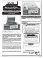
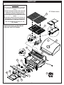
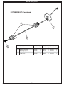
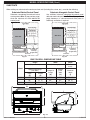
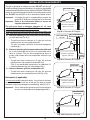
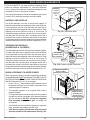
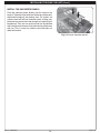
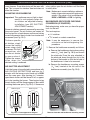
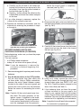
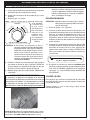
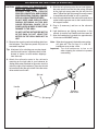
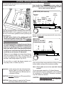
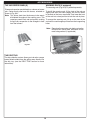
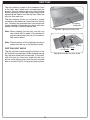
24, 30, and 36 SERIES
OUTDOOR GAS BARBECUES
SLIDE-IN MODEL
INSTALLATION AND OPERATING
INSTRUCTIONS
SAFETY WARNINGS & CODES
Important:
Read these instructions carefully
before starting installation.
INSTALLER: Leave these instructions with consumer.
CONSUMER: Retain for future reference.
WARNING
1. Do not store or use gasoline or other
flammable vapors and liquids in the
vicinity of this or any other appliance.
2. A propane cylinder not connected for use
shall not be stored in the vicinity of this
or any other appliance.
CODE AND SUPPLY REQUIREMENTS: This
barbecue must be installed in accordance with
local codes and ordinances, or, in the absence of
local codes, with either the latest National Fuel Gas
Code (ANSI Z223.1/NFPA 54), and Natural Gas and
Propane Installation Code (CSA-B149.1).
This appliance and its individual shutoff valves must
be disconnected from the gas supply piping system
when testing the system at pressures in excess of
½ psig (3.5 kPa).
This appliance must be isolated from the gas supply
piping system by closing its individual manual
shutoff valves during any pressure testing of the
gas supply system at pressures up to and including
½ psig (3.5 kPa).
WARNING
Improper installation, adjustment,
alteration, service, or maintenance
can cause injury or property damage.
Refer to this manual. For assistance or
additional information, consult a qualified
professional installer, service agency, or
the gas supplier.
DANGER
IF YOU SMELL GAS:
1.
2.
3.
4.
All electrical outlets in the vicinity of the barbecue
must be properly grounded in accordance with local
codes or, in the absence of local codes, with the
National Electrical Code, ANSI/NFPA 70, or the
Canadian Electrical Code, CSA C22.1, whichever
is applicable.
Keep all electrical supply cords and fuel supply
hoses away from any heated surface.
Shut off the gas to the appliance.
Extinguish any open flame.
Open lid if equipped with an oven.
If odor continues, keep away from the
appliance, and immediately call the gas
supplier or fire department.
Certified to ANSI: Z21.58b-2012
CSA: 1.6b-2012
09-06
American Outdoor Grill • PO Box 4053 • La Puente, CA 91747
REV 11 -1408070855
1
L-C2-179
24, 30 et 36 SÉRIES
LE GAZ EXTÉRIEUR GRILLE TOUT
ENTIER LE MODÈLE DE SLIDE-IN
INSTALLATION ET CONSIGNES
D’UTILISATION
AVERTISSEMENTS ET CODES DE SÛRETÉ
Important:
Lisez ces instructions
soigneusement avant de
commencer l’installation.
INSTALLATEUR: Laissez ces instructions avec le
consommateur.
CONSOMMATEUR: Maintenez pour la future référence.
AVERTISSEMENT
1. Ne pas entreposer ni utiliser de l’essence ni
d’autres vapeurs ou liquides inflammables
dans le voisinage de l’appareil, ni de
proximité de tout autre appareil.
2. Une bouteille de propane qui nest pas
raccordée en vue de son utilisation, ne doit
pas être entreposée dans le voisinage de
cet appareil ou de tout autre appareil.
CONDITIONS
DE
CODE
ET
D’APPROVISIONNEMENT: Ce barbecue doit
être installé selon des codes et des ordonnances
locaux, ou, en l’absence des codes locaux, avec
l’un ou l’autre le plus défunt code national de gaz
de carburant (norme ANSI Z223.1/NFPA 54), et le
code d’installation de gaz naturel et de propane
(CSA-B149.1).
Cet appareil et ses différents robinets d’isolement
doivent être démontés du système sifflant d’offre
de gaz en examinant le système aux pressions audessus du ½ psig (kPa 3.5).
AVERTISSEMENT
L’installation inexacte, l’ajustement, le
changement, le service ou l’entretien
peuvent causer des dommages ou
des dégats matériels. Référez-vous à
ce manuel. Pour l’aide ou l’information
additionnelle consultez un installateur
qualifié et professionnel, l’agence de
service, ou le fournisseur de gaz.
Cet appareil doit être isolé dans le système sifflant d’offre
de gaz par fermeture ses différents robinets d’isolement
manuels pendant tous les essais sous pression du circuit
d’alimentation de gaz aux pressions jusques et y compris
DANGER
S’il y a une odeur de gaz:
1. Coupez l’admission de gaz de l’appareil.
2. Éteindre toute flamme nue.
3. Ouvrir le couvercle.
4. Si l’odeur persiste, gardez loin de l’appareil,
et appelez immédiatement le fournisseur de
gazou le service d’incendie.
Toutes les sorties électriques à proximité du barbecue
doivent être correctement fondues selon des codes
locaux ou, en l’absence des codes locaux, avec le code
électrique national, ANSI/NFPA 70, ou le code électrique
canadien, CSA C22.1, qui est jamais applicable.
Gardez tout cordon d’alimentation électrique et tuyau
d’alimentation en combustible a l’écart des surfaces
chauffées.
Certifié à la norme ANSI : Z21.58b-2012
CSA : 1.6b-2012
09-06
American Outdoor Grill • PO Box 4053 • La Puente, CA 91747
REV 11 -1408070855
2
L-C2-179
TABLE OF CONTENTS
1
5
8
8
9
9
10
11
11
11
12
12
12
12
13
13
13
15
17
17
18
18
19
20
22
23
23
23
25
26
27
27
28
28
29
30
31
32
SAFETY WARNINGS & CODES
PARTS LIST
MODEL SPECIFICATIONS
COUNTERTOP OVERHANG
SUBSTRATE
BUILT-IN GRILL DIMENSIONS TABLE
INSTALLATION REQUIREMENTS
ENSURING PROPER COMBUSTION AIR AND COOLING AIRFLOW
EXHAUST REMOVAL
GAS-SUPPLY PLUMBING REQUIREMENTS
ENCLOSURE REQUIREMENTS
NATURAL GAS INSTALLS
PROPANE GAS INSTALLS (HOUSEHOLD & CYLINDER)
WHEN A PROPANE CYLINDER IS USED
INSTALLING THE BUILT-IN UNIT
COUNTER PREPARATION
CONNECTING THE GAS SUPPLY
SAFE USE & MAINTENANCE OF PROPANE GAS CYLINDERS
CHECKING AND CONVERTING GAS TYPE
CHECKING AND CONVERTING THE REGULATOR (if applicable)
CHECKING/CONVERTING THE BURNER ORIFICES
MAIN BURNER ORIFICE SIZE CHECKING/CONVERSION
BACKBURNER ORIFICE SIZE CHECKING/CONVERSION (IF EQUIPPED)
INFRARED BURNER ORIFICE SIZE CHECKING/CONVERSION (IF EQUIPPED)
BARBECUE SAFETY INFORMATION & MAINTENANCE
LIGHTING (IGNITION) INSTRUCTIONS
ELECTRONIC LIGHTING
MANUAL LIGHTING
ROTISSERIE INSTRUCTIONS (IF EQUIPPED)
OPTIONAL INFRARED BURNER OPERATION
TROUBLESHOOTING
REPLACING THE IGNITOR BATTERY
ACCESSORIES
THE VAPORIZER PANEL(S)
DRIP TRAY
NOTES PAGE
CARE & CLEANING
WARRANTY
REV 11 -1408070855
3
L-C2-179
AVERTISSEMENTS
Avertissements généraux :
• Ce barbecue est pour ultilisation à l’extérieur seulement. Si l’appareil est entreposé à l’intérieur,
enlever les bouteilles et les laisser à l’extérieur.
• Ne pas ranger le gril immédiatement aprés l’avoir utilisé. le laisser refroidir avant de le déplacer
ou de la ranger. Le non respect de cette mesure de sécurité pourrait entraîner un incendie
causant des dommages à la propriété, des blessures ou la mort.
• Ne pas utiliser cet appareil sous une surface combustible.
• Ne pas utiliser cet appareil sous un auvent. Le non respect de cette mesure de sécurité pourrait
entraîner un incendie ou des blessures.
• Dégagement minimal entre les parois latérales et l’arriére de l’appareil et la construction
combustible (45.7 cm à partir des parois latérales et 45.7cm à partir de l’arriére).
• Le régulareur de pression de gaz prévu avec cet appareil de cuisson à gaz pour l’extérieur
doit être utilisé. Ce régulateur est réglé pour une pression de sortie de 5 pouces de colonne
de l’eau pour le gaz naturel, et 10 pouces pour le propane.
• LE RÉGULATEUR INCLUS D’APPAREILS EST ÉVALUÉ POUR LE MAXIMUM DE 1/2 (LIVRES
PAR POUCE CARRÉ). SI VOTRE OFFRE DE GAZ EST 1/2 PLUS GRAND QUE (LIVRES
PAR POUCE CARRÉ), UN RÉGULATEUR ADDITIONNEL DOIT ÊTRE INSTALLÉ AVANT LE
BARBECUE. VOIR LA SECTION DE CONDITIONS D’OFFRE DE GAZ POUR LA PRESSION
APPROPRIÉE D’OFFRE DE GAZ.
• Ne couvrez jamais la surface entière de cuisine ou de gril de gauffreuses ou de casseroles.
La surchauffe se produira et les brûleurs ne seront pas très performants quand la chaleur de
combustion est emprisonnée au-dessous de la surface à cuire.
• Ne pulvérisez jamais l’eau sur une unité chaude de gaz, comme ceci peut endommager des
composants de porcelaine ou de fer de fonte.
Avertissements de propane :
• Une fuite de GPL peut causer une incendie ou une explosion si enflammée entraînant des
blessures corporelles graves ou la mort.
• Communiquez avec le fournisseur de GPL pour les réparations ou pour disposer de qules
bouteille ou du GPL non utilisé.
REV 11 -1408070855
4
L-C2-179
PARTS LIST
IMPORTANT
This AOG oven and backburner (if equipped)
are fully pre-assembled and tested at the
factory.
24" Model shown
DO NOT attempt to remove the oven and
backburner from the barbecue prior to
or during installation or damage to the
connecting gas line and ignitor wiring may
occur.
1
The plastic straps that secure the oven to
the barbecue unit must be removed and
discarded prior to lighting the barbecue.
This note applies for all 3 size (24", 30",
36") models.
2
Replacement parts can be ordered
from your local AOG dealer.
4
3
7
6
8
14
5
12
13
10
18
9
17
11
15
REV 11 -1408070855
16
5
L-C2-179
PARTS LIST (Cont.)
24"
Item
Description
Part No.
30"
Qty. Part No.
36"
Qty.
Part No.
Qty.
1
36-B-11
1
1.
Stainless cooking grid (set of 2 or 3)
24-B-11
1
30-B-11
2.
Vaporizer panel
24-B-05
2
30-B-05-03
3
36-B-05
3
3.
Main burner
24-B-06
2
24-B-06
3
24-B-06
3
4.
Infrared burner (optional)
IRB-18
1
IRB-18
1
IRB-18
1
5.
Backburner*
24-B-17
1
24-B-17
1
36-B-17
1
6.
Thermometer
24-B-10
1
24-B-10
1
24-B-10
1
7.
Oven lid
24-B-25
1
30-B-25
1
36-B-25
1
8.
Warming rack*
24-B-02
1
30-B-02
1
36-B-02
1
9.
Drip tray with match holder
3083
1
3083
1
3083
1
10.
Control panel w/ backburner
24-B-26
1
30-B-26
1
36-B-26
1
or
Control panel w/o backburner
24-B-27
1
30-B-27
1
36-B-27
1
3199-48
1†
N/A
3199-47
1†
3199-47
2
3199-47
2
11.
Electronic ignitor (4 spark)
and/or Electronic ignitor (2 spark)
N/A
12.
Valve manifold w/ backburner
24-B-08
1
30-B-08
1
36-B-08
1
or
Valve manifold w/o backburner
24-B-34
1
30-B-34
1
36-B-34
1
13.
Heat shield
24-B-15
1
30-B-15
2
36-B-15
2
14.
Main burner electrode
24-B-04
2
24-B-04
3
24-B-04
3
15.
Barbecue knob
3015
2
3015
3
3015
3
16.
Backburner knob*
3016
1
3016
1
3016
1
17.
Regulator
PR-4
1
PR-4
1
PR-4
1
18.
Drip tray heat shield
24-B-44
1
24-B-44
1
24-B-44
1
* If equipped
† Quantities may vary due to burner options.
REV 11 -1408070855
6
L-C2-179
PARTS LIST (Cont.)
ROTISSERIE KIT (if equipped)
2
1
3
4
REV 11 -1408070855
24"
Item Description
Part No.
30"
Qty. Part No.
36"
Qty.
Part No.
Qty.
1.
Stainless steel motor
24-B-32
1
24-B-32
1
24-B-32
1
2.
24-B-18
1
24-B-18
1
24-B-18
1
3.
Spit prongs (set of 2)
Spit rod 5/8" hex
24-B-33
1
30-B-33
1
36-B-33
1
4.
Handle knob
24-B-09
1
24-B-09
1
24-B-09
1
7
L-C2-179
MODEL SPECIFICATIONS
MODEL SPECIFICATIONS TABLE
Table 1
24"
30"
36"
2
#46/#1.20
3
#50/#56
3
#46/#1.20
#54/#65
#54/#65
#54/#65
#46/#1.20
#50/#56
#46/#1.20
Insulating liner model # (not included)*
24-IL
30-IL
36-IL
A Countertop to unit bottom cut-out*
8 1/2"
8 1/2"
8 1/2"
B Side to side non-combustible cut-out*
24 1/2"
30 5/8"
36 7/8"
C Front to back non-combustible cut-out*†
19 1/2"
19 1/2"
19 1/2"
D Control panel width non-combustible cut-out‡
25 1/2"
31 5/8"
37 7/8"
Main burner Quantity
N/P orifice drill size
Backburner ▲
N/P orifice drill size
Infrared searing burner ▲
N/P orifice drill size
▲
If equipped
*Note:
If installing this grill in a combustible enclosure, the correct AOG insulating liner must
be used. Consult liner instructions for counter cut-out dimensions and installation.
† Includes any substrate at front wall of enclosure (in the area the rear of the control panel
is to sit flush against). See SUBSTRATE section on next page.
‡ Only applicable for non-combustible enclosures that have countertops with an overhang
(see illustration and section below).
X= 1/2"
TOP VIEW
TOP VIEW
B
Countertop
C
(Countertop)
X
NON-COMBUSTIBLE
ENCLOSURE CUT-OUT
DIMENSIONS
(Control
panel)
Lower support
Control panel
Y= Total
Countertop
Overhang
Countertop
overhang
Y (Overhang)
1/4"
Clearance
D
Check clearance for
control panel removal
FRONT VIEW
SIDE VIEW
A
Countertop
overhang
Control
panel
Countertop
overhang
See next page
for substrate
considerations
Fig. 8-1
COUNTERTOP OVERHANG
The control panel is designed to sit flush against the enclosure front wall. If the non-combustible enclosure countertop
extends beyond the front wall, creating a countertop overhang, it must be cut flush with the front wall for the width of
the control panel or a gap will be created exposing the forward portions of the left and right side grill fire walls. See
illustrations above.
Important:
FOR YOUR SAFETY, you must provide openings in the island enclosure for drainage, replacement
air, and cross-ventilation of any storage area exposed to possible leakage from gas connections, the
unit, or propane bottles. See the ENCLOSURE REQUIREMENTS section for details.
REV 11 -1408070855
8
L-C2-179
MODEL SPECIFICATIONS (Cont.)
SUBSTRATE
When adding any substrate to the enclosure front wall (including tiles, stone, etc.), consider the following:
Substrate Behind Control Panel
Substrate Alongside Control Panel
Substrate + countertop "front to back" cutout
must equate to Dim. C (see previous page)
when the substrate sits flush behind the
control panel.
Any additional substrate alongside the control panel
does not need to be considered in Dim. C (see previous
page), however a 1/4" clearance on each side (same as
overhang) and below is required.
TOP VIEW
TOP VIEW
C
Grill liner
(Countertop)
(Countertop)
Substrate
(includes tiles,
etc. at front of
enclosure)
Substrate
(includes tiles,
etc. at front of
enclosure)
Flush
Flush
(Control panel)
C
Grill liner
(Control panel)
Countertop
overhang
1/4" (if applicable)
Clearance
Countertop
overhang
(if applicable)
1/4"
Clearance
Fig. 9-1
Fig. 9-2
BUILT-IN GRILL DIMENSIONS TABLE
Model
Height
Width
Depth
(Top to bottom)
(Left to right)
(Front to
back)
Upper hanger to top
(with oven)
Hanger to
hanger
(G)
Control
panel
width
(H)
Maximum
depth
(I)
Open
(E)
Closed
(F)
24"
22"
11 1/2"
28"
25"
26 1/4"
30"
22"
11 1/2"
34"
31"
26 1/4"
36"
22"
11 1/2"
40 1/4"
37 1/4"
26 1/4"
G
I
E
F
H
Fig. 9-3
REV 11 -1408070855
9
L-C2-179
INSTALLATION REQUIREMENTS
This grill is designed for outdoor use only. DO NOT use this grill
inside a building, garage, enclosed area, or under an unprotected
overhead combustible construction. See the EXHAUST REMOVAL
section on the following page for details on installing under a patio
roof. DO NOT use this grill in or on a recreational vehicle or boat.
Non-combustible
Min.
4"
Important: If installing this grill in a combustible surround, the
correct R.H. Peterson insulating liner must be used.
Important: Refer to the information below to ensure all
required clearances are met.
The grill must have a minimum clearance of 18" from
combustible materials/items AT ALL TIMES.
For the minimum clearances between the grill and any side or rear
walls, your setup must fall within one (or more) of the following:
A. Clearance between grill and strictly non-combustible wall
(i.e. brick wall, see Fig. 10-1)
• The grill must have a minimum of 4" right, left, and rear
clearance from any non-combustible wall.
(To allow for proper ventilation and prevent dangerous
overheating.)
B. Clearance between grill and a protected combustible wall
(i.e. a non-combustible wall in front of a combustible wall to
serve as a barrier. This can be accomplished by brick, or
a metal stud finished with non-combustible substrate, see
Fig. 10-2)
• The grill must have a minimum of 14" right, left, and rear
clearance from the protected combustible wall.
(The 4" non-combustible material plus an additional 10"
clearance between the grill and protected wall.)
(Clearance required for
right, left, and rear)
Fig. 10-1 Clearance 'A' Diagram
Non-combustible
substrate
Non-combustible 4"
Min.
14"
Combustible
(Clearance required for
right, left, and rear)
Fig. 10-2 Clearance 'B' Diagram
Combustible
C. Clearance between grill and combustible wall
Min.
18"
• The grill must have a minimum of 18" right, left, and rear
clearance from any combustible wall (see Fig. 10-3).
Backsplash (if applicable)
If a non-combustible backsplash exists, it must have a minimum
of a 4" clearance from the rear of the grill (to allow for proper
ventilation and prevent dangerous overheating). See Fig. 10-4.
Important: This 4" backsplash clearance must first be met prior
to any non-combustible walls beginning behind it.
(Clearance required for
right, left, and rear)
Fig. 10-3 Clearance 'C' Diagram
Non-combustible
Backsplash
Min.
4"
Fig. 10-4 Backsplash clearance
REV 11 -1408070855
10
L-C2-179
INSTALLATION REQUIREMENTS (Cont.)
The control panel MUST remain removable for servicing
(see PARTS LIST).
ENSURING PROPER COMBUSTION AIR AND
COOLING AIRFLOW
Proper airflow (Fig. 11-1) MUST be maintained for the
grill to perform as it was designed. If airflow is blocked,
overheating and poor combustion will result. Do not
block the 1" (2.5 cm) front air inlet along the bottom of
the control panel or more than 75% of the cooking grid
surface with pans or griddles.
Note: The 1" (2.5 cm)
front air space
also allows
access to the
drip tray.
GAS-SUPPLY PLUMBING REQUIREMENTS
For natural gas or a household propane system, rigid 1/2"
(1.3 cm) or 3/4" (1.9 cm) black steel pipe or local codeapproved pipe is required to conduct the gas supply to
the unit. Contact your local gas supplier. Connect this
pipe to the supplied regulator. See the CONNECTING
TO GAS SUPPLY section for complete details. DO NOT
use a rubber hose within the grill enclosure. Apply
only joint compounds that are resistant to all gasses to
all male pipe fittings except flare fittings. Make sure to
tighten every joint securely.
Note: If 1/2" (1.3 cm) pipe is used with natural gas, it
should be no longer than 20' (6.1 meters).
Important:
CAUTION: Wind blowing into or across the rear
oven lid vent (Fig. 11-2) can cause
poor performance and/or dangerous
overheating. Orient the grill so that the
prevailing wind blows toward the front of
the grill (Fig. 11-3).
Fig. 11-1
Ventilation Diagram
EXHAUST REMOVAL
If installed or used under a patio roof, the cooking grid
area must be fully covered by an exhaust hood with a
vent. An exhaust fan with a rating of 1,000 CFM (cubic
feet per minute) (472 liters per second) or more may be
necessary to effectively remove smoke and other cooking
by-products from the area under the hood. This grill must
not be used under unprotected overhead combustible
construction. THIS UNIT MUST NOT BE LOCATED IN
A FULLY ENCLOSED AREA OF ANY KIND.
INCORRECT
An external valve (with a removable key) in
the gas line is necessary for safety when
the grill is not in use. It also provides for
convenient maintenance.
GAS SUPPLY AND MANIFOLD PRESSURES:
For natural gas - normal 7" (17.78 cm) water column
(w.c.), minimum 5" (12.7 cm), maximum 10 1/2" (26.7
cm). For propane gas - normal 11" w.c., minimum 10"
(25.4 cm), maximum 13" (33 cm).
CORRECT
CORR
CO
RREC
ECT
T
Rear oven lid vent
YOU MUST PROTECT REAR OVEN
VENT FROM PREVAILING WIND
Fig. 11-2
REV 11 -1408070855
PLACE GRILL SO PREVAILING WIND
BLOWS TOWARD FRONT OF GRILL
Fig. 11-3
11
L-C2-179
ENCLOSURE REQUIREMENTS
FOR YOUR SAFETY, you must provide the openings listed
below for drainage, replacement air, and cross-ventilation
of any storage area exposed to possible leakage from gas
connections, the unit, or propane cylinders.
One side of the enclosure can be left completely open to the
outside, OR 4 ventilation openings must be created:
Nat. gas
installs
L.P. gas
installs
(repeat for
opposite
side)
(repeat for
opposite
side)
NATURAL GAS INSTALLS
Two of the openings are to be at the top level (approx. 4"
below the countertop) and on opposite walls of the enclosure.
2 more openings must be at the floor level (no more than 5"
above the floor) and on opposite sides of the enclosure. Each
opening must have a minimum of 10 sq. in. of free area. To
achieve the proper ventilation, you may drill a series of holes,
omit the grout from masonry joints, or replace a brick with a
hardware cloth screen. If the floor in the cabinet is raised and
the space beneath the cabinet is open to the outside, the lower
ventilation openings may be in the floor. Reference Fig. 12-1.
Fig. 12-1 Ventilation detail
PROPANE GAS INSTALLS
(HOUSEHOLD & CYLINDER)
Grill
Heatshield
Two of the openings are to be at the cylinder valve level (approx.
16" above the floor) and on opposite walls of the enclosure.
2 more openings must be at the floor level (no more than 5"
above the floor) and on opposite sides of the enclosure. Each
opening must have a minimum of 10 sq. in. of free area. To
achieve the proper ventilation, you may drill a series of holes,
omit the grout from masonry joints, or replace a brick with a
hardware cloth screen. If the floor in the cabinet is raised and
the space beneath the cabinet is open to the outside, the lower
ventilation openings may be in the floor. Reference Fig. 12-1.
C.S.A. listed
stainless steel
flex connector
Adapter
L.P.
cylinder
Regulator/
hose
assembly
Fig. 12-2 Propane cylinder orientation
Cylinder & regulator/
hose assembly
protected by heatshield
WHEN A PROPANE CYLINDER IS USED
When a propane cylinder is installed inside of the enclosure,
the guidelines below MUST be followed. FAILURE TO DO SO
MAY CAUSE DAMAGE TO YOUR UNIT AND/OR PERSONAL
INJURY. Reference Fig. 12-2 for an example.
• Only a C.S.A. 1/2" listed stainless steel connector can be
connected to the grill (not included). Installation of the
supplied regulator is optional.
• The supplied regulator is not required when using a
propane cylinder.
• The regulator/hose assembly coming from the propane
cylinder can only be connected to the above mentioned
grill flex connector. DO NOT connect the regulator/
hose assembly directly to the grill. An adapter will
be required.
Equipped with
adapter for hose
assembly and
flex connector
Fig. 12-3 Optional AOG door w/tank tray
• A heatshield must be installed to protect the regulator/
hose assembly and propane cylinder valve.
• AOG offers a propane cylinder door with tank tray to
meet the cylinder install requirements. See Fig. 12-3.
REV 11 -1408070855
12
L-C2-179
INSTALLING THE BUILT-IN UNIT
COUNTER PREPARATION
Consult Table 1 for non-combustible enclosure cut-out
dimensions. An AOG insulating liner must be used if the
counter or any supporting construction is combustible.
Consult the instructions that come with the liner for
dimensions and additional installation information before
beginning the installation.
This outdoor built-in grill must be supported by the
stainless-steel hanger extending from the upper portion
of the grill. The hanger rests on the left, right, and back
of the countertop.
For household propane or natural gas units:
THE SUPPLIED REGULATOR MUST BE REMOTELY
ATTACHED IN-LINE BETWEEN THE GAS SUPPLY AND
THE UNIT.
CAUTION: Use only C.S.A. listed stainless-steel flex
connectors within the enclosure.
WARNING
A rubber or plastic connector will rupture or leak,
resulting in an explosion or serious injury if used
inside the appliance enclosure.
The control panel is designed to sit flush against the
enclosure front wall (see Fig. 13-2). If the non-combustible
countertop extends beyond the front wall, creating a
countertop overhang (see Fig. 13-1), it must be cut flush
with the front wall for the width of the control panel or
a gap will be created exposing the forward portions of
the left and right side grill fire walls. See the MODEL
SPECIFICATIONS section.
Note: It is not necessary to remove the control panel
or knobs to install this unit.
CONNECTING THE GAS SUPPLY
Always ensure the orifices and regulator are set for
the gas type your unit is to be installed to.
For propane cylinders:
For connecting a propane unit to a portable propane tank,
read the safety warnings and follow the instructions in the
section SAFE USE AND MAINTENANCE OF PROPANE
GAS CYLINDERS.
Note: When a propane cylinder is installed inside
of the enclosure, the guidelines found in the
ENCLOSURE REQUIREMENTS section
MUST be followed.
a. Connect a C.S.A. listed 1/2" flex connector (not
included) to the adapter found on the manifold.
b. Install a 1/2" flare - 1/2" NPT adapter to the flex
connector (not included). Then connect the supplied
regulator to the adapter using pipe joint compound
resistant to all gasses. Orient so that the arrow
stamped on the regulator points in the direction of
the gas flow.
c. Run the gas supply pipe and install to the regulator.
Use pipe joint compound resistant to all gasses.
Ensure connections are tight. (An adapter is
required if the gas supply pipe is other than 1/2" in
diameter.)
d. Turn all burner control knobs to the OFF position.
Turn the gas supply on. Then carefully check all gas
connections for leaks with a brush and half-soap/
half-water solution before lighting. Never use a
match or open flame to test for leaks.
e. Close the dedicated gas-supply shut-off valve, then
slide the grill into place. Do not to pinch, kink, or
damage the gas connector line.
control panel
stops here
Countertop
Proposed cutout in overhang
GAP CREATED
Fig. 13-1
REV 11 -1408070855
Dedicated manual
shut-off valve
Countertop
(Grill)
Overhang
Regulator
6" Grill clearance
IDEAL
Flush-mounted
control panel
Flex connector
(not included)
Adapter (not included)
Gas supply
Fig. 13-3
Fig. 13-2
13
L-C2-179
INSTALLING THE BUILT-IN UNIT (Cont.)
INSTALL THE VAPORIZER PANELS
Place the vaporizer panels directly onto the studs on the
burners. The panels allow heat from the burners to be evenly
distributed throughout the cooking area. The panels are
stainless steel and will heat and cool quickly, making your
barbecue very responsive to the changes you specify in grill
temperature. They are rust resistant and may be cleaned
with standard oven cleaners. Some discoloring will be seen
with use. This is normal for stainless steel and does not
affect the function.
Place onto studs
Fig. 14-1 Install vaporizer panels
REV 11 -1408070855
14
L-C2-179
SAFE USE & MAINTENANCE OF PROPANE GAS CYLINDERS
IMPORTANT FOR YOUR SAFETY
READ AND FOLLOW ALL WARNINGS PROVIDED WITH THE PROPANE-GAS CYLINDER.
When operating this appliance with a propane-gas cylinder, these instructions and warnings MUST be observed.
FAILURE TO DO SO MAY RESULT IN A SERIOUS FIRE OR EXPLOSION.
CYLINDER/CONNECTOR REQUIREMENTS
a. Propane-gas cylinders, valves, and hoses must be
maintained in good condition and must be replaced if
there is visible damage to either the cylinder or valve. If the
hose is cut or shows excessive abrasion or wear, it must
be replaced before using the gas appliance (see e.).
The use of pliers or a wrench should not be necessary. Only
cylinders marked “propane” may be used.
To disconnect: Turn the hand nut counterclockwise until
detached (Fig. 15-1).
Important:
Before using the unit, and after each time the
cylinder is removed and reattached, check
the hose for wear (see a.) and check all
connections for leaks. Turn off the unit valves
and open the main cylinder valve, then check
connections with soapy water. Repair any
leaks before lighting the unit.
CAUTION:
Always turn the propane cylinder main valve
off after each use, and before moving the unit
and cylinder or disconnecting the coupling.
This valve must remain closed and the
cylinder disconnected while the appliance
is not in use, even though the gas flow is
stopped by a safety feature when the coupler
is disconnected.
b. This unit, when used with a cylinder, should be connected
to a standard 5-gallon (20 lb.) propane-gas cylinder
equipped with an OPD (Overfill Prevention Device).
The OPD has been required on all cylinders sold since
October 1,1998, to prevent overfilling.
c. Cylinder dimensions should be approximately 12" (30.5
cm) in diameter and 18" (45.7 cm) high. Cylinders must
be constructed and marked in accordance with the
Specifications for Propane Gas Cylinders of the U.S.
Department of Transportation (D.O.T.) or the National
Standard of Canada, CAN/CSA-B339, Cylinders,
Spheres, and Tubes for Transportation of Dangerous
Goods.
d. The cylinder used must include a collar to protect the
cylinder valve, and the cylinder supply system must be
arranged for vapor withdrawal.
e. The
The pressure
pressure regulator
regulator and
and hose
hose assembly
assembly (Fig.
used 15-1)
must
match
the
specifi
cation
for
Type
I
by
ANSI
Z
21.58-2005/
supplied with this outdoor gas appliance (L.P. models
CGA must
1.6-2005
(see Fig.
15-1).
only)
be used.
Original
and replacement pressure
regulator and hose assemblies must be those specified
by the manufacturer for connection with a cylinder
connecting device identified as Type I by the ANSI Z
21.58-2005/CGA 1.6-2005 (see PARTS LIST for ordering
information).
f.
Carefully inspect the hose assembly each time before the
gas is turned on. A cracked or frayed hose must be replaced
immediately.
If the appliance is stored indoors, the cylinder must be
disconnected and removed. Disconnected cylinders must be
stored outdoors, out of the reach of children, with threaded
valve plugs tightly installed, and must not be stored in a
building, garage, or any other enclosed area.
FOR YOUR SAFETY
The propane-gas cylinder valve must be equipped with a
cylinder connection coupling device, described as Type I
in the standard defined in paragraph e. above. This device
is commonly described as an Acme thread quick coupler.
g. If the propane-gas cylinder comes with a dust plug, place
the dust cap on the cylinder valve outlet whenever the
cylinder is not in use.
QUICK COUPLER OPERATION
To connect the regulator/hose assembly to the propanegas cylinder valve fitting: Press the hand nut on the regulator
over the Acme thread fitting on the cylinder valve. Turn the hand
nut clockwise to engage the threads and tighten until snug.
a. DO NOT store a spare propane-gas cylinder under or
near this appliance.
b. NEVER fill the cylinder beyond 80-percent full.
c. IF THE INFORMATION IN a. AND b. IS NOT FOLLOWED
EXACTLY, A FIRE CAUSING DEATH OR SERIOUS
INJURY MAY OCCUR.
Fig. 15-1 Type I Acme thread quick coupler
QCC
Type 1
valve
Pressure
relief
valve
Hand wheel
Brass Acme
thread fitting
Regulator
UL
Liquid level
indicator
(optional)
Hand nut with Acme
thread
For propane ventilation requirements, see the ENCLOSURE REQUIREMENTS section.
15
Vent
Hose
UTILISATION SÛRE ET ENTRETIEN DES CYLINDRES DE GAZ DE PROPANE
IMPORTANT POUR VOTRE SÛRETÉ
LISEZ ET SUIVEZ TOUS LES AVERTISSEMENTS ÉQUIPÉS DE VOTRE CYLINDRE DE GAZ DE PROPANE.
En actionnant cet appareil avec un cylindre de gaz de propane ON DOIT observer ces instructions et avertissements.
LE MANQUE DE FAIRE AINSI PEUT AVOIR COMME CONSÉQUENCE UNE INCENDIE OU UNE EXPLOSION SÉRIEUSE.
main dans le sens des aiguilles d’une montre pour engager les
CYLINDRE ET CONDITIONS ET
fils et pour serrer jusqu’à ce que douillettement. L’utilisation des
CARACTÉRISTIQUES DE CONNECTEUR
pinces ou de la clé ne devrait pas être nécessaire. Seulement
a. Des cylindres et les valves de gaz de propane doivent être
le propane marqué par cylindres doit être employé.
maintenus en bon état et doivent être remplacés s’il y a
Pour débrancher: Tournez l’écrou de main dans le sens
des dommages évidents au cylindre ou à la valve.
b. Ce gril, une fois utilisé avec un cylindre, devrait être relié à contraire des aiguilles d’une montre jusqu’à isolé (fig. 16-1).
c.
d.
e.
e.
f.
g.
un gallon de la norme 5 (20lb.) cylindre de gaz de propane
équipé d’un OPD (remplissez au-dessus du niveau le
dispositif d’empêchement). L’OPD a été exigé sur tous les
cylindres vendus depuis octobre 1.1998 pour empêcher le
remplissage excessif.
Les dimensions de cylindre devraient être approximativement
12"(30.5cm) de diamètre et 18" (45.7cm) hauts. Des
cylindres doivent être construits et marqués selon les
caractéristiques pour des cylindres de gaz de propane du
département des ETATS-UNIS du transport (D.O.T.) ou
le niveau national du Canada, du CAN/CSA-B339, des
cylindres, des sphères et des tubes pour le transport des
marchandises dangereuses.
Le cylindre doit inclure un collier pour protéger la valve
de cylindre et le circuit d’alimentation de cylindre doit être
assuré le retrait de vapeur.
Le
du de
régulateur
deet
pression
et le flexible
(Fig.utilisé
16-1)
Le montage
régulateur
pression
l’ensemble
de tuyau
fourni
avec
cet
appareil
au
gaz
en
plein
air
(modèles
au
doivent assortir les spécifications pour le type I par ANSI
propane
seulement)
doit
être
utilisé.
Assemblées
d'origine
et
Z 21.58-2005/CGA 1.6-2005 (voir la figue. 16-1).
régulateur de pression et le tuyau de remplacement doivent
être ceux spécifiés par le fabricant pour le raccordement d'un
dispositif de cylindre de liaison identifiée comme de type I par
le 21.58-2005/CGA ANSI Z 1.6 à 2005 (voir liste des pièces
pour les informations de commande).
La valve de cylindre de gaz de propane doit être équipée
d’un dispositif d’accouplement de raccordement de
cylindre, décrit comme type I dans la norme définie dans le
e. de paragraphe ci-dessus. Ce dispositif est généralement
décrit comme coupleur rapide de fil de point culminant.
Si votre cylindre de gaz de propane vient avec une prise
de la poussière, placez le bouchon anti-poussière sur la
sortie de valve de cylindre toutes les fois que le cylindre
n’est pas en service.
Important:
Avant d’employer le gril, et ensuite chaque
fois que le cylindre est enlevé et rattaché,
examinez tous les raccordements pour déceler
les fuites. Arrêtez les valves de gril et ouvrez
la valve principale de cylindre, puis vérifiez
les raccordements avec de l’eau savonneux.
Réparez toutes les fuites avant d’allumer le gril.
ATTENTION: Tournez toujours la valve principale de cylindre
de propane au loin après chaque utilisation,
et avant de déplacer le gril et le cylindre, ou
débrancher l’accouplement. Cette valve doit
rester fermée et le cylindre a débranché alors
que l’appareil n’est pas en service, quoique
l’écoulement de gaz soit arrêté par un dispositif
de sûreté quand le coupleur est débranché.
Inspectez soigneusement l’ensemble de tuyau chaque fois
avant que le gaz soit allumé. Un tuyau fissuré ou effiloché doit
être immédiatement remplacé.
Si l'appareil est stocké à l'intérieur, le cylindre doit être disconnected
et a enlevé. Des cylindres Disconnected doivent être stockés
dehors, hors de la portée des enfants, avec les prises de valve
filetées étroitement installées, et ne doivent pas être stockés dans
un bâtiment, le garage, ou n'importe quel autre secteur inclus.
POUR VOTRE SÛRETÉ
OPÉRATION DE COUPLEUR RAPIDE
a. Ne stockez pas un cylindre de gaz disponible de propane
dessous ou ne vous approchez pas de cet appareil.
b. Ne remplissez jamais cylindre au delà de 80 pour cent de
plein.
c. SI L’INFORMATION DANS “A” ET “B” N’EST PAS SUIVIE
EXACTEMENT, UN FEU CAUSANT LA MORT OU DES
DOMMAGES SÉRIEUX PEUT SE PRODUIRE.
Fig. 16-1 type coupleur rapide de fil de point culminant d’I
Volant de commande
QCC
Type 1
4
1
Ajustage de précision
3
en laiton de fil de
point culminant
Régulateur
Valve
Pour relier le regulator/hose à l’ajustage de précision de
valve de cylindre de gaz de propane: Serrez l’écrou de main
sur le régulateur au-dessus de l’ajustage de précision de fil
de point culminant sur la valve de cylindre. Tournez l’écrou de
Valve
de
décompression
UL
2
Indicateur
de niveau
de liquide
(facultatif)
Écrou de main avec le
fil de point culminant.
Pour la ventilation de propane, voir la section sur les exigences de boîtier.
16
Passage
Tuyau
CHECKING AND CONVERTING GAS TYPE
This unit comes from the factory configured for one type
WARNING
of gas, as marked on the label located behind the control HAZARDOUS OVERHEATING WILL OCCUR IF A
panel, or on the interior of the unit’s enclosure.
NATURAL-GAS ORIFICE IS USED WITH PROPANE
Converting this unit to burn a different type of gas GAS. IF YOU ARE NOT SURE IF THE CORRECT
requires a conversion kit (contact your dealer for ORIFICES ARE INSTALLED, OR IF AN ORIFICE
details). The professional installer who converts this CHANGE IS NECESSARY, REFER TO THE FOLLOWING
unit to burn a different gas must perform the following INSTRUCTIONS.
functions:
CAUTION: Make sure the unit is at a safe temperature
and isolated from gas and electrical
1. Change brass gas orifices (included at original shipping)
supplies before beginning the tasks
on each burner to match the new gas type (see
outlined below.
PRODUCT DATA TABLE, Table 1).
2. If applicable, switch the convertible gas regulator to
match the new gas type (see section below).
Note: The cooler the unit, the greater the tolerances
between the stainless-steel parts, and therefore
the easier to disassemble and reassemble
parts of the unit.
Note: Models to be connected to household propane
or natural gas lines require the regulator. For
models to be connected to L.P. Cylinders, the
regulator is optional.
CAUTION: For your safety, exercise caution and
use adequate hand protection (such as
gloves) when handling potentially sharp
3. Plumb the unit as appropriate for the new gas supply.
sheet-metal parts.
4. Apply the label for the new gas (included at original
shipping) over the old gas information found on your
unit.
CHECKING AND CONVERTING THE REGULATOR (if applicable)
Regulator: note cap on top
Note: Each end of the plastic converter is engraved with either the letters “NAT”
or “L.P.” (propane) for the respective gasses. When the converter is in the
cap and the cap is held uppermost, the letters seen indicate the gas that
the regulator is set up for.
To convert the regulator from one gas to another, follow steps 1-4.
STEP 1:
Unscrew and remove the cap from the
regulator, extracting the converter.
Read gas
type here
STEP 2:
Remove the converter (the
plastic stalk) by carefully
pulling it away from the center
of the cap (it will snap out of
its seating).
STEP 3:
Turn the converter around and
replace it carefully, into the
center of the cap (it will snap
into place). Check that you can
read the type of gas the unit is
set for.
STEP 4:
Replace the unit into the
regulator and screw down
until snug.
WARNING
THIS APPLIANCE REGULATOR IS RATED FOR 1/2 PSI MAXIMUM. IF YOUR GAS SUPPLY IS
GREATER THAN 1/2 PSI, AN ADDITIONAL REGULATOR MUST BE INSTALLED TO REDUCE
THE INPUT PRESSURE TO THE UNIT to 1/2 PSI OR LESS. SEE GAS-SUPPLY REQUIREMENTS
SECTION FOR PROPER GAS-SUPPLY PRESSURE.
17
CHECKING/CONVERTING THE BURNER ORIFICES
MAIN BURNER ORIFICE SIZE CHECKING/
CONVERSION
Before beginning, make sure you have the proper
tools for the task.
This task requires:
• a #2 Phillips-head screwdriver
• a deep 3/8" nut driver with a spacer (#6 nut)
Note: It may be necessary to remove the rotisserie
rod before beginning this procedure.
1. Remove cooking grids & vaporizer panels from the
barbecue.
2. Turn the burner valves to the OFF position.
Pull the valve knobs from their stems and
set them aside. Using a Phillips screwdriver,
unscrew the control panel fastener screws,
(located on the sides of the control panel) and
remove the control panel from the barbecue.
Retain the screws for reattaching the control
panel.
Burner
support
Removing/inserting main burner.
Burner
support
Burner
Clip
Hole with
orifice
Fig. 18-1
Note: Carefully, lift the control panel away from
the frame. The spark generator for the
ignition system is attached to the inside
of the control panel. The spark generator
knob need not be detached, but the wires
must be unplugged from the generator
before the control panel is completely
removed (see Fig. 18-2).
3. Slightly pinch and remove the burner clip
(located over the rear center of the burner) from
the burner support and set aside. Then carefully
lift the burner from the burner support and out
from the hole in the forward fire wall (see Fig.
18-1).
Valve
4. Using a 3/8" socket, remove the orifice from
the valve. Access this through the hole in the
forward firebox plate (see PARTS LIST and
Fig. 18-1). Check the number stamped on the
face of the orifice (see Table 1). Repeat for
each burner as necessary.
5. If the barbecue does not have the proper
orifices installed for the gas supply you
intend to use, replace them with the correct
orifices. Some orifices were supplied with the
barbecue. They may also be obtained from the
conversion kit or supplied by your local dealer.
Note: A regulator hose will need to be connected
for conversion to propane gas.
6. After checking the
orifice drill size
or replacing the
orifice, replace
the burner over
the orifice fitting,
Fig. 18-2
sliding it forward,
Spark generator
from behind the
forward fire wall, so the orifice is centered
inside the burner gas inlet, and set it gently
onto the burner support. The studs on the
bottom back of the burner must each fit
through their respective holes in the burner
support. This is critical to the safe function of
the barbecue. Finally, re-install the burner clip
(from step 3) around the burner and into the
corresponding holes in the burner support (see
Fig. 18-1).
INSTALL THE VAPORIZER PANELS
Place the vaporizer panels directly onto the studs on
the burners. The panels allow heat from the burners
to be evenly distributed throughout the cooking area.
The panels are stainless steel and will heat and cool
quickly, making your barbecue very responsive to
the changes you specify in grill temperature. They
are rust resistant and may be cleaned with standard
Continued on next page
Burner
Orifice
Fig. 18-3 - Burner orifice diagram
18
CHECKING/CONVERTING THE BURNER ORIFICES (Cont.)
oven cleaners. Some discoloring will be seen with
use. This is normal for stainless steel and does not
affect the function.
ADJUSTING YOUR BARBECUE
Important: This appliance may not light or heat
evenly or cook properly unless the
air shutters are adjusted following
installation (see AIR SHUTTER
ADJUSTMENT section).
Burner air shutters are easily accessed by removing
the control panel. The air shutters are located on
the front portion of each burner and have a locking
screw that prevents the air shutter from inadvertent
movement (see Fig. 19-1).
To close or open the
air shutters, simply
loosen the locking
screw, using a long
Air shutter
stemmed Phillips
screwdriver, and
turn the air shutter
Locking
to open or close it.
screw
Tighten the screws
Fig. 19-1
d ow n w h e n t h e
desired setting is achieved.
a lazy yellow, open the air shutters until the flame
is mostly blue.
Note: Barbecues in some installations achieve a
better air/gas mixture and will ignite more
quickly if the valve is first turned beyond
HIGH to MEDIUM or LOW for lighting.
BACKBURNER ORIFICE SIZE CHECKING/
CONVERSION (IF EQUIPPED)
Before beginning, make sure you have the proper
tools for the task.
This task requires:
• a 1/4" nutdriver
• a 3/8" wrench or socket screwdriver
Note: It may be necessary to remove the
rotisserie rod before beginning this
procedure.
1. Remove the backburner assembly as follows:
a. Remove the backburner electrode mounting
screw (1/4" hex) (see Fig. 19-3) and loosen
the electrode. Draw the wire attached to
the electrode down through the slot in the
bottom of the bracket so that the left side of
the backburner is free to be removed.
b. Remove the backburner mounting screws
(1/4" hex) located at the left end of the
backburner assembly (see Fig. 19-3).
AIR SHUTTER ADJUSTMENT
Light the burner to be adjusted in accordance with
the LIGHTING INSTRUCTIONS and burn for 2
minutes with the burner control knob set to HIGH
and the oven open. After burning for 2 minutes,
open the air shutter until the flames lift off, or appear
not to be touching the burner. Then begin closing
the air shutter until the flames appear to burn while
touching the burner ports (Fig. 19-2). If flames are
Flame off ports
Mounting screws
Flame on ports
Ignitor
screw
Electrode
Fig. 19-3
Fig. 19-2 - Flame appearance diagram
Remove electrode and backburner mounting screws.
19
CHECKING/CONVERTING THE BURNER ORIFICES (Cont.)
c. Carefully pull the left end of the backburner
forward until the burner can be moved to the
left pulling it free from the orifice located on
the right side (see Fig. 20-1).
before the control panel is completely
removed (see Fig. 20-1).
d. Using a 3/8" socket, remove the orifice from the
orifice holder and check the number stamped
on the face.
2. If an orifice change is necessary, replace the
orifice with the correctly sized one.
3. Replace the backburner assembly and the
electrode by reversing the procedure in steps
a. through c.
Fig. 20-1
Spark generator
3. Disconnect the ignitor wire from the bottom of
the electrode assembly on the infrared burner
(see Fig. 20-2).
Orifice
Backburner
Fig. 20-2
Spark generator
Fig. 20-1
The backburner orifice can be seen on the
right side after removing the backburner.
4. Carefully lift the infrared burner from the burner
support and out from the hole in the forward
fire wall (see Fig. 20-3).
INFRARED BURNER ORIFICE SIZE
CHECKING/CONVERSION (IF EQUIPPED)
Removing / inserting infrared burner.
Before beginning, make sure you have the proper
tools for the task.
This task requires:
• a #2 Phillips-head screwdriver
• a deep 3/8" nut driver with a spacer (#6 nut)
Note: It may be necessary to remove the
rotisserie rod before beginning this
procedure.
1. Remove cooking grids & vaporizer panels from the
barbecue.
2. Turn the burner valves to the OFF position.
Pull the valve knobs from their stems and
set them aside. Using a Phillips screwdriver,
unscrew the control panel fastener screws,
(located on the sides of the control panel) and
remove the control panel from the barbecue.
Retain the screws for reattaching the control
panel.
Note: Carefully, lift the control panel away from
the frame. The spark generator for the
ignition system is attached to the inside
of the control panel. The spark generator
knob need not be detached, but the wires
must be unplugged from the generator
20
Hole with
orifice
Wire disconnected
Burner
support
Fig. 20-3
5. Using a 3/8" socket, remove the orifice from
the valve. Access this through the hole in the
forward firebox plate (see PARTS LIST and
Fig. 20-3). Check the number stamped on the
face of the orifice (see Table 1).
6. If the barbecue does not have the proper
orifices installed for the gas supply you
intend to use, replace them with the correct
orifices. Some orifices were supplied with the
barbecue. They may also be obtained from the
conversion kit or supplied by your local dealer.
Note: A regulator hose will need to be connected
for conversion to propane gas.
CHECKING/CONVERTING THE BURNER ORIFICES (Cont.)
7. After checking the orifice drill size or replacing
the orifice, replace the infrared burner over the
orifice fitting, sliding it forward, from behind the
forward fire wall, so the orifice is centered inside
the burner gas inlet, and set it gently onto the
burner support. The tabs on the bottom back of
the burner must each fit through their respective
slots in the burner support. This is critical to the
safe function of the barbecue.
8. Reconnect the ignitor wire to the bottom of the
electrode assembly on the infrared burner.
21
BARBECUE SAFETY INFORMATION & MAINTENANCE
Each time you use the barbecue, make sure that:
DRIP COLLECTION SYSTEM
1. The area around the barbecue is clear of flammable
vapors, liquids, and substances such as gasoline,
yard debris, wood, etc.
2. There is no blockage of the airflow through the vent
space located below the control panel.
3. When using propane gas:
a. The special ventilation openings in the enclosure
should be kept free and clear of debris
(see PLANNING THE LOCATION OF THE
BARBECUE).
b. If connected to a propane cylinder, the rubber
hose attached to the regulator should be carefully
inspected before each use.
c. The propane cylinder, regulator, and rubber hose should
be installed in a location not subject to heating above
125° F (51° C).
4. The burner flames burn evenly along both sides
of each burner with a steady flame, which is
mostly blue. (Refer to section on AIR SHUTTER
ADJUSTMENT.) A proper flame pattern will ensure
safe operation and optimal performance. Adjust
the air shutter as needed. If burner flames are not
normal, check the orifice and burner for insects or
insect nests.
The drip collector in this barbecue is part of the unit’s
main frame and is located below the burners. The drip
collector has slots that will allow excess drippings to
fall through during cooking, while separating the firebox
from the drip tray. Clean the drip tray after each use.
The drip collector allows you to brush or scrape residue
from the barbecue’s inner liner into the drip tray.
Following the manufacturers instructions and regular
cleaning of the barbecue’s interior with oven cleaner,
will help to prevent grease fires.
Periodically check the burners to make sure they are
clear of debris. Properly adjusted burner flames burn
evenly along both sides of each burner with a steady
flame (mostly blue). If burner flames are not normal,
check the orifice and burner for insects or insect nests.
(See section on CHECKING/CONVERTING THE
BURNER ORIFICES for instructions on burner removal
and replacement.)
Check the burner ports at least annually for blockage by
removing the burner (see orifice changing instructions)
and visually inspect the gas intake tube for insects
and nests. A clogged tube can lead to a fire beneath
the grill.
5. The inline gas valve or gas cylinder valve is always
shut OFF when the barbecue is not in use.
6. The drip collector hole is clear and unobstructed.
Excessive grease deposits can result in a grease
fire.
7. The barbecue is free and clear from combustible
materials, gasoline, and other flammable vapors
and liquids.
8. The infrared burner cover (if equipped) must be
removed before using the burner.
WARNING
NEVER cover the entire cooking or grill surface with griddles or pans. Overheating will occur and
burners will not perform properly when combustion heat is trapped below the cooking surface.
CAUTION: NEVER spray water on a hot gas unit.
The grill serial identification number is located on the underside of the drip tray handle. It
is recommended that the drip tray first be removed and cleaned / emptied of its contents,
then turned over to view.
22
LIGHTING (IGNITION) INSTRUCTIONS
Read entire instructions before lighting, and follow these instructions each time you light the grill.
ELECTRONIC LIGHTING
MANUAL LIGHTING
1. Open all lids and remove all covers from the burners CAUTION: Always wait five minutes for gas to clear
you wish to light.
after any unsuccessful lighting attempt.
2. Turn all gas control knobs to their OFF positions.
3. Turn on the gas at its source.
OFF
OONN
RNRN
TUTU
TOT O
Note: No matter which lighting method you use,
DO NOT turn
Read
setting
Read setting
on the gas
here
here
to more than
F
FFF
OO
N
N
one bur ner
R
UR
TTU
O
at a time.
TOT
Adjacent grill
High to
HIGH to
light
bu r n e r s w i l l
LIGHT
cross-ignite,
and
gas
flow may be
Fig. 23-1 - Valve control knob
restricted.
1. Follow steps 1 through 4 (left).
2. Insert either a burning long-barrel butane lighter,
a burning long-stem match, or a burning match
held by a wire extension holder (Fig. 23-2) through
the cooking grids to the burner (Fig. 23-3).
For backburners, hold the flame against the
p e r f o r a t e d m a t e r i a l o f t h e b a c k b u r n e r.
For sideburners, hold the flame against the burner.
HI
LIGHT
3. While holding the match or lighter flame next to the
burner, depress the appropriate burner control knob
and turn it counterclockwise to the HI LIGHT position.
LOW
Fig. 23-2 - Match holder
CAUTION:
If the burners do not light within five
seconds, depress the control knob
and turn the knob to OFF. WAIT FIVE
MINUTES before repeating step 4. If you
smell gas, follow the instructions on the
cover of this manual. If the burners still do
not light after several attempts, refer to the
instructions for MANUAL LIGHTING.
4. Depress the control knob for the burner to be lit
and turn it to the HI LIGHT position, then press the
ignition button. Once the burner lights, release the
ignition button.
When the burner lights, remove the lighter or match.
4. If the burner does not light, IMMEDIATELY depress the
knob and turn the burner control knob to OFF. WAIT
FIVE MINUTES before repeating steps 2 through 4
of the MANUAL LIGHTING INSTRUCTIONS.
Note: Some installations achieve a better air/gas
mixture and may ignite quicker if the burner
control knob is first turned beyond HI LIGHT
to LOW for lighting.
5. Repeat step 4 for each additional burner to be lit.
FOR PROPANE ONLY
Propane tanks are equipped with a safety shutdown
device that may cause low or no gas pressure/flame
at the burners if operating and lighting instructions
are not followed exactly (See important note in the
TROUBLESHOOTING section for more details.)
Fig. 23-3 - Manual lighting
REMEMBER: FOR SAFE MANUAL LIGHTING, PLACE A
BURNING MATCH OR BUTANE LIGHTER BESIDE THE
BURNER - THEN TURN ON THE GAS (see Fig. 23-3).
SHUTTING OFF THE GRILL
To shut off the grill, push in each valve control knob and
turn it clockwise to the OFF position.
Always close the valve to the gas supply after each use
of the grill.
23
ALLUMER DES INSTRUCTIONS (D’ALLUMAGE)
Lisez l’instruction entière avant que s’allumant et suivez ces instructions chaque fois vous lumière le barbecue.
Note: Les barbecues dans quelques installations
ÉCLAIRAGE ÉLECTRONIQUE
réalisent un meilleur mélange d’air/gas et mettront
1. Ouvrez tous les couvercles et enlevez toutes les couvertures
à feu plus rapidement si le bouton de commande de
des brûleurs que vous souhaitez vous allumer.
brûleur est d’abord tourné au delà de la LUMIÈRE
de HI au BAS pour l’éclairage.
2. Arrêtez tous les boutons de commande de gaz à leurs
positions.
ÉCLAIRAGE MANUEL
3. Allumez le gaz à sa source.
Note:
Aucune matière que la méthode d’éclairage
vous emploient,
Read
setting
Read setting
here
here
n’allument pas
F
F
F
le gaz à plus
F
OO
N
N
R
d’un brûleur à la
R
OFF
U
TTU
O
fois. Les brûleurs
O
TT
adjacents de
High to
HIGH to
light
barbecue croixLIGHT
mettront à feu
et l’écoulement
de gaz peut être
restreint.
Fig. 24-1 - Valve control knob
OONN
RNRN
TUTU
TOT O
ATTENTION: Attendez toujours 5 minutes le gaz à l’espace
libre après que n’importe quelle tentative non
réussie d’éclairage.
1. Suivez les étapes 1 à 4 (à gauche).
HI
LIGHT
2. Insérez un allumeur brûlant de butane de long-baril, une
allumette brûlante de long-tige, ou une allumette brûlante
tenue par un support de prolongation de fil (Fig. 24-2)
par les grilles à cuire au brûleur (Fig. 24-3). Pour des
backburners, tenez la flamme contre le matériel perforé
du brûleur arrière. Pour des sideburners, tenez la flamme
contre le brûleur.
LOW
3. Tout en tenant l’allumette ou la flamme plus légère à côté
du brûleur, enfoncez le bouton de commande approprié
de brûleur et tournez-le dans le sens contraire des
aiguilles d’une montre dans la position LÉGÈRE de HI.
Quand les lumières de brûleur, enlèvent l’allumeur ou
s’assortissent.
ATTENTION: Si les brûleurs ne s’allument pas dans 5
secondes, enfoncez le bouton de commande
et tournez le bouton à AU LOIN. ATTENDEZ 5
MINUTES avant de répéter l’étape 5. Si vous
sentez le gaz suivez les instructions sur la
couverture de ce manuel. Si les brûleurs ne
s’allument toujours pas après que plusieurs
tentatives, se rapportent aux instructions pour
l’ÉCLAIRAGE MANUEL.
Fig. 24-2 - Support d’allumette
4. Enfoncez le bouton de commande pour que le brûleur
soit allumé et tournez-le dans la position LÉGÈRE de
HI, puis appuyez sur le bouton d’allumage. Une fois que
le brûleur s’allume, libérez le bouton d’allumage.
4. Si le brûleur ne s’allume pas, enfoncez immédiatement
le bouton et tournez le bouton de commande de brûleur
à AU LOIN. ATTENDEZ 5 MINUTES avant de répéter
les étapes 2 à 4 des INSTRUCTIONS MANUELLES
d’ÉCLAIRAGE.
5. Répétez l’étape 4 pour que chaque brûleur additionnel soit
s’est allumé.
POUR LE PROPANE SEULEMENT
COUPER LE GRIL
Les réservoirs de propane sont équipés d’un dispositif
d’arrêt de sûreté qui peut ne pas causer le bas ou aucun gaz
pressure/flame aux brûleurs si le fonctionnement et allumer
des instructions ne sont pas suivis exactement (voir la note
importante dans la section de dépannage pour plus de détails.)
Pour couper le gril, enfoncez chaque bouton de commande
de valve et tournez-le dans le sens des aiguilles d’une montre
à la position de repos.
Fermez toujours la valve à l’offre de gaz après chaque
utilisation du barbecue.
Fig. 24-3 - Éclairage manuel
RAPPELEZ-VOUS: POUR L’ÉCLAIRAGE MANUEL SÛR, PLACEZ
Un ALLUMEUR BRÛLANT D’ALLUMETTE OU De BUTANE PRÈS
Du BRÛLEUR - ALLUMEZ ALORS Le GAZ (voyez Fig. 24-3).
24
ROTISSERIE INSTRUCTIONS (IF EQUIPPED)
CAUTION: WHEN USING THE BACKBURNER;
KEEP THE OVEN LID CLOSED TO
PREVENT HEAT LOSS, PROVIDE
PROPER CONVECTION, AND PROVIDE
PROPER VENTING. THIS WILL ENSURE
EVEN COOKING TEMPERATURES.
3. Slide the left spit prong onto the rod (and tighten),
the meat onto the rod and into the prong, followed
by the right spit prong onto the rod and into the
meat. Tighten the right spit prong. Be sure the meat
is centered and balanced as well as possible.
4. Insert the pointed end of the rod into the motor drive
socket and the groove next to the handle into the
left support bracket.
DO NOT KEEP YOUR OVEN LID OPEN
DURING ROTISSING, AS THIS MAY
CAUSE PERSONAL INJURY, OR IN
SOME CASES, IN WINDY CONDITIONS,
DAMAGE TO THE GRILL.
5. Plug in (if necessary) and turn on the rotisserie
motor.
6. Light backburner per lighting instructions in this
manual (or on drip tray handle) and close oven lid.
DO NOT USE THE ROTISSERIE MOTOR
IN THE RAIN. DO NOT LEAVE THE
MOTOR ON THE GRILL WHEN NOT IN
USE.
7. Allow the backburner to preheat for approximately
10 minutes on HI LIGHT setting.
1. Remove the warming rack and cooking grids from
the barbecue. The vaporizer panels may also be
removed if required.
Note: When burning properly, the backburner grating
will glow red. The first time it is used the
backburner may smoke a little.
Tip: Aluminum foil or a baking pan may be placed
over the main burners / vaporizer panels, a little
forward of center, to catch excess drippings
from the meat.
Important: Tur n the backbur ner to low or off
when stopping the rotisserie to prevent
overcooking.
2. Attach the rotisserie motor to the rotisserie
mounting on the right side of your barbecue by
sliding the bracket attached to the motor onto the
tab on the right of the barbecue. The motor should
be installed so that the spit rod will fit into the motor
drive socket from the left.
Spit rod
Handle
Stainless
steel motor
Spit prongs
25
OPTIONAL INFRARED BURNER OPERATION
The infrared (IR) searing burner (optional) cooks with
WARNING
a powerful radiant heat.
Only handle the infrared burner cover when the
grill is cold or with a well-insulated long-handled
tool or heat resistant gloves.
Cover
SIDE VIEW (with cover on)
Ignitor
electrode
NO foreign
objects
Drippings
and other
Airborne liquids
dust or
grease
Ignitor
electrode
Fig. 26-1
Cover
Food
particles
or debris
OFF
HI
LIGHT
Fig. 26-2
LOW
Light the infrared burner following the LIGHTING
INSTRUCTIONS in this manual or printed on the
drip tray. Follow these guidelines when operating the
Infrared burner:
• DO NOT place food on the cooking grid until
the IR burner glows orange (Fig. 26-3). Drippings
are heated and evaporate instead of sticking to and
impairing burner function.
Burner ceramic must be protected with cover when
burner is not in use.
SIDE VIEW
(burner on HI LIGHT
and glowing orange)
Ignitor
electrode
• For cleaning purposes; always leave your burner
on (after cooking) for an additional 5 minutes, to
allow for a burnoff period. This is important to
keep your burner clean and operating properly.
As the burner is self cleaning (at full temperature);
avoid the use of cleaners or abrasives.
• Do not strike or scratch the burner ceramic as it
may chip, crack, or break (Fig. 26-2).
Note: Digital thermometer does not give accurate
readings for infrared burners.
OFF
HI
LIGHT
LOW
• When not in use, always cover the infrared burner
with the stainless-steel cover. This protects the
burner from drippings (from other cooking), airborne
particles, and foreign objects (Fig. 26-2).
Fig. 26-3
Drips and particles evaporate before hitting infrared
burner when cooking at the maximum setting.
Note: Flavor grids are not to be used with infrared
burners.
Important: When grilling with the infrared burner,
always place a cooking grid above it.
The cooking grid must be removed for
rotisserie cooking.
To ensure proper operation, all infrared burners
(back and main) must be operated on the HI setting
for a minimum of 10 minutes. Thereafter, the flame
may be lowered as desired.
CAUTION: DO NOT operate your IR burner with the
oven hood closed.
CAUTION: Always monitor the infrared burner flame
when operated on low, as it may blow
out in high-wind conditions.
CAUTION: Never attempt to operate the IR burner
with the protective cover in place.
26
TROUBLESHOOTING
If you have trouble with the unit, please use this list to identify the problem. By trying one or more of the
solutions to the possible cause, you should be able to solve the problem. If this list does not cover your
present problem, or if you have other technical difficulties with the unit, please contact your local dealer.
PROBLEM
Ignition system
failure
Insufficient heat /
low flame
Uneven heating
POSSIBLE CAUSE
1) Improper air shutter adjustment
1) Adjust air shutters.
2) Ignition wire disconnected
2) Replug wires into generator.
3) Low gas pressure
3) Have gas company check the
operating pressure at the unit.
4) Dead battery
4) Replace battery.
1) Improper air shutter adjustment
1) Adjust air shutters.
2) Using propane orifice for natural gas
2) Change orifices.
3) Low gas pressure/flame (natural)
3) Have gas company check the
operating pressure at the unit.
4) Low gas pressure/flame (propane)
4) Refill propane tank, or reset
propane tank safety*: Shut off all
valves (including propane tank) and
follow lighting instructions exactly.
5) L.P. regulator hose cracked due to age
5) Replace L.P. regulator hose.
1) Burner ports partially blocked by debris
1) Remove burners and clean out ports.
2) Small spiders or insects in burner
2) Inspect burners for spider webs or
other debris that may block gas flow.
1) Va l ve “ L o w ” s e t t i n g n e e d s
adjustment
1) Light burner on HIGH, immediately
turn to LOW setting. Remove
knob from valve and using a small
flat screwdriver, slowly turn the
adjustment screw in the stem,
a little at a time (30° to 45°), in
either direction, until the flame is
approximately 1/4” in height from
burner ports.
Burner goes out on
LOW
Rotisserie noisy
CORRECTION
1) Rotisserie out of balance
1) Adjust
Adjust counterbalance.
the meat on the spit rod.
Note: *Propane tanks are equipped with a safety shutdown device that may cause low or no gas/flame at the
burners if operating and lighting instructions are not followed exactly. If you suspect the propane tank
safety shutoff is in effect, shut off all burner control valves and the propane tank valve. Then read and
follow the LIGHTING INSTRUCTIONS exactly. Lighting instructions are located in the owner’s manual. If
the problem persists, continue troubleshooting, or contact your local dealer or distributor for assistance.
REPLACING THE IGNITOR BATTERY
1. Remove the ignitor cover by turning it counterclockwise.
Note: If you have accidentally removed the rubber cap,
follow the instructions below to replace it.
Important: Do not
attempt to pull or
turn the rubber cap.
2. Remove batter y for
replacement. The battery
is reinstalled with the
negative (-) end out.
1. Pull the rubber
cap and the inner
WRONG!!
plastic sleeve
3. After properly inserting the apart.
battery, replace the ignitor cover
by turning the cap clockwise.
27
2. Carefully insert
the rubber cap into
the ignitor cover so
it sits behind inner
lip.
3. Tu r n t h e c a p
over and slide the
inner plastic sleeve
into the cap.
ACCESSORIES
WARMING RACK (if equipped)
THE VAPORIZER PANEL(S)
The warming rack (Fig. 28-2) is packed separately.
Place each vaporizer panel directly on a burner or burner
pair. Center each panel over the burner, oriented as To install the warming rack, lift the front of the rack up
slightly and insert the rack hangers into the two holes
shown in Fig. 28-1.
in the back of the inner oven hood. Then lower the front
Note: This allows heat from the burners to be evenly of the rack into a level position to lock the rack in place.
distributed throughout the cooking area. The
vaporizer panels heat and cool quickly, making To remove the warming rack, lift up on the front of the
the grill very responsive to the changes in heat rack until the rack hangers pull free from their supporting
holes.
from the burners.
Note: Removing the warming rack before using the
rotisserie will leave more clearance for the
meat being cooked. (if applicable)
Fig. 28-1
Fig. 28-2 Warming rack in place inside oven
THE DRIP TRAY
The drip collection system allows you to brush or scrape
excess dried residue from the grilling area directly into
the drip tray (see the DRIP TRAY section for more
information).
28
DRIP TRAY
The drip collection system in this barbecue is part
of the unit’s main frame and is located below the
burners. The drip collector has slots that will allow
excess drippings to fall through during cooking, while
separating the firebox from the drip tray. Clean the
drip tray after each use.
The drip collector allows you to brush or scrape
residue from the barbecue’s inner liner into the drip
tray. Following the manufacturers instructions and
regular cleaning of the barbecue’s interior with oven
cleaner, will help to prevent grease fires.
Lighting
instructions
Fig. 29-1 Lighting instruction plate
Note: When cleaning the drip tray, the drip tray
heat shield will first need to be removed to
properly clean/empty the tray of its contents.
See section below.
A
B
Note: There are easy to follow lighting instructions
etched onto the top of the drip tray handle.
Drip tray
Tab on inside
DRIP TRAY HEAT SHIELD
Tab on outside
The drip tray heat shield provides protection to the
grill controls from high heat. When cleaning the drip
tray, the heat shield must be removed. To re-install,
slide the front lip of the heat shield into the front
portion of the drip tray, then orient the front and side
tabs as shown in Fig. 29-2 to properly drop in place.
29
Fig. 29-2 Install drip tray heat shield
NOTES PAGE
Please use this page to record any information about your unit that you may want to have at hand.
30
CARE & CLEANING
APPLIANCE MUST BE COMPLETELY COOL WHEN
CLEANING. DO NOT SPRAY ANY CLEANER OR
LIQUIDS ON THE APPLIANCE WHEN HOT.
The appliance must be cleaned as often as once a month
(depending on use) to prevent grease build-up and other
food deposits.
Wipe with grain
INTERIOR
THE BURNER PORTS AND CARRY-OVER PORTS/
SLOTS MUST BE KEPT CLEAN TO ENSURE PROPER
IGNITION AND OPERATION.
Fig. 31-1 - Wipe with grain
Remove the burner (see orifice changing instructions)
and clean the ports and slots as required. Also inspect
and clean the burner inlet for insects and nests. A clogged
burner can lead to a fire in the bottom of the appliance. PROTECTING YOUR APPLIANCE FROM THE
The inside of the appliance may be cleaned periodically WEATHER
with oven cleaner if desired. Follow the oven cleaner
An optional cover will protect your appliance when not
instructions for proper use.
in use. (Allow to cool before covering.)
Be careful not to get oven cleaner on the outside surface
Please specify the model number and serial number
of the appliance as it can permanently damage the finish.
of your appliance when ordering a cover.
EXTERIOR
Stainless steel surfaces when exposed to temperatures
produced by the grilling process will change color. The
stainless steel will change color from silver to brown
and blue. This can be removed by using stainless steel
cleaner.
Clean your appliance by first using grill cleaner to remove
grease and dirt. Always wipe with the grain (See Fig.
31-1). Next, use stainless steel cleaner to restore the
stainless steel color (Note: not for mirror finish). Finish
by wiping your appliance down using polish wipes. To
clean any mirror finish (if applicable), use a quality
brand glass cleaner only, not any of the cleaners
mentioned above.
IMPORTANT
IN THE EVENT OF A GREASE FIRE, IMMEDIATELY
SHUT OFF THE MAIN GAS VALVE TO THE GRILL.
KEEP THE LID OPEN AND ALLOW THE FIRE TO
EXTINGUISH ITSELF. A THOROUGH INSPECTION
BY A TRAINED SERVICE TECHNICIAN SHOULD
BE CONDUCTED BEFORE FUTURE USE OF YOUR
GRILL. THE SERVICE TECHNICIAN WILL CHECK
THE SYSTEM FOR GAS LEAKS AND WILL CHECK
If your appliance is installed in a seaside (salt air) or ALL ELECTRICAL WIRING FOR DAMAGE. ALL GAS
poolside (chlorine) location, it will be more susceptible LEAKS AND WIRING MUST BE REPAIRED PRIOR
to corrosion and must be maintained/cleaned more TO FUTURE USE.
frequently. Do not store chemicals (such as chlorine or
fertilizer) near your stainless steel appliance.
Due to the nature of stainless steel, surface iron oxide
deposits may appear. Do not be alarmed – these deposits
are removable with stainless steel cleaner through prompt
and periodic maintenance. If not attended to promptly,
permanent pitting may occur.
By following these recommendations, you will enjoy the
beauty and convenience of your appliance for many years
to come.
31
WARRANTY
AMERICAN OUTDOOR GRILL
LIMITED WARRANTY
American Outdoor Grill warrants your grill to be free from defects in material and workmanship.
American Outdoor Grill stainless-steel burners are warranted for FIFTEEN (15) YEARS. All other American Outdoor Grill parts are
warranted for TEN (10) YEARS. (Except as noted below.)
American Outdoor Grill infrared burners and vaporizer panels are warranted for THREE (3) YEARS.
American Outdoor Grill ignition systems (excluding batteries) and accesories (including sideburners, motors, and thermometers) are
warranted for ONE (1) YEAR.
A COPY OF YOUR SALES SLIP FOR PROOF OF PURCHASE IS REQUIRED
This warranty applies to the original purchaser for products which are installed in the United States or Canada and which are operated and maintained
as intended for single family residential usage. This warranty is valid only with proof of purchase, shall commence on the date of purchase, and shall
terminate (both as to original and any replacement products) on the anniversary date of the original purchase of the product stated on the above schedules.
This warranty covers defects in material and workmanship. This warranty does not cover parts which become defective as a result of negligence, misuse,
use not in compliance with the Owner’s Manual/Installation Instructions, accidental damage, improper handling, improper storage, improper installation,
lack of required routine maintenance (as specified in the Owner’s Manual/Installation Instructions), electrical damage, local gas impurities or failure to
protect against combustibles. Product must be installed (and gas must be connected) as specified in the Owner’s Manual/Installation Instructions by
a qualified professional installer. Modifications to products which are not specifically authorized will void this warranty. Accessories, parts, valves,
remotes, etc. when used must be Peterson products or this warranty is void. Warrantied items will be repaired or replaced at Peterson’s sole discretion.
This warranty does not apply to rust, corrosion, oxidation, or discoloration unless the affected part becomes inoperable.
This warranty does not cover labor or labor related charges, except as provided by separate specific written programs from the Peterson Co. All repair
work must be performed by a qualified professional service person and requires prior approval of Peterson.
Peterson may require the defective product or part to be returned to the factory to determine the cause of failure. Peterson will pay freight charges if
the product or part is determined to be defective. This warranty does not cover breakage in shipment from our (Independent) distributor to its customer
if the damage is determined to have occurred during that shipment.
This warranty specifically excludes liability for indirect, incidental, or consequential damages. Some states and provinces do not allow the exclusion
or limitation of incidental or consequential damages, so the above exclusion may not apply to you. This warranty gives you specified legal rights, and
you may have other rights that vary from state to state or province.
For additional information regarding this warranty, or to place a warranty claim, contact the R. H. Peterson dealer where the product was purchased.
TO REGISTER
YOUR PRODUCT
TO: AMERICANOUTDOORGRILL
WWW.RHPETERSON.COM, .COM,
TO REGISTER
YOUR PRODUCT
ONLINEONLINE
GO TO:GO
WWW.
AND CLICK ON PRODUCT REGISTRATION. THANK YOU FOR YOUR PURCHASE.
Quality Check
Burner Orifices Nat.
Date:_________________
L.P.
Leak Test: ___________ Model#:
___________________
Main:
____ ____
Burn Test: ___________ Serial#:
___________________
Back:
____ ____
Gas Type:
Side/Power:
____ ____
Infrared:
____ ____
Other:
____ ____
Nat. / L.P.
Air Shutter: ___________________
Inspector:
___________________
Robert H.Outdoor
Peterson Grill
Co. • •14724
East
Proctor
Avenue• •City
City of Industry,
American
14724
Proctor
Avenue
Industry,CA
CA91746
91746
32