1
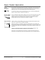
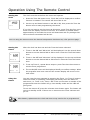
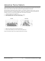
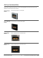
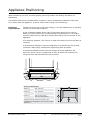
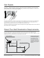
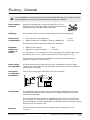
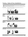
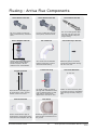
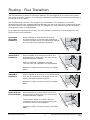
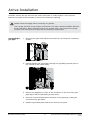
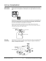
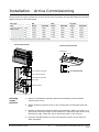
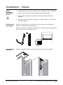
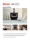
Arriva Operation and Installation Manual ® SENSITIVE CHOICE SUPP OR T IN G A S T H M A CA RE Approved by the Asthma and Respiratory Foundation Appliance must be installed with an approved Rinnai flue system. Appliance must be installed, commissioned and serviced by a licensed tradesperson in accordance with these instructions and all applicable local rules and regulations. Owner, please retain this manual for future reference. Limited Warranty Rinnai brings you peace of mind with a 2 year minimum warranty. TERMS AND CONDITIONS 1. During the 24 month period from date of purchase and subject to clauses 2 and 3 below, Rinnai New Zealand Limited (“Rinnai”) will, at its own discretion, either replace or repair any defective product at no charge to the customer. 2. This warranty covers manufacturing defects only. This warranty will not apply if (for example) the product has been improperly installed or is otherwise installed contrary to manufacturer’s recommendations, has been damaged during or after installation, has not been operated in accordance with operating instructions, or has been subjected to damage or abuse beyond that expected from conditions of normal use. 3. Warranty claims may be invalid if not accompanied by details of the installing or supervising gas fitter’s registration number and the gas fitting certification number. 4. This warranty commences from the date of purchase. Proof of purchase is required at the time of any warranty claim. 5. Servicing of the product is to be carried out by a Rinnai authorised service centre. All Rinnai appliances meet or exceed the safety standards required by New Zealand gas and electrical regulations. The company is constantly improving its products and as such specifications are subject to change or variation without notice. Please keep these instructions in a safe place for future reference. RECORD AND ATTACH YOUR PROOF OF PURCHASE BELOW: Your Retailer:__________________________________________________ Name:________________________________________________________ Address:______________________________________________________ _____________________________________________________________ Telephone:( _______ ) __________________________________________ Date of Purchase: ______ / ______ / _________ Contents Customer Information Limited Warranty 2 About Your Arriva 4 Safety 5 Clearances 6 Mantles and Surrounds 7 General Information 8 Basic Heater Operation 10 Operation Using Remote Control 12 Care and Maintenance 15 Servicing 17 Abnormal Flame Pattern 18 Troubleshooting 19 Arriva Accessories 22 Installer Information General and Specification 24 Appliance Positioning 25 Gas Supply and Direct Flue Wall Penetrations 26 Flueing 27 Arriva Installation 32 Installing the Log Set 35 Commissioning 37 Setting Air Guide Vanes 38 Front Fascia and Top Panel 39 Wiring Diagrams 40 Commissioning Checklist 42 Installer Details 43 Customer Contacts 44 WARNING Improper installation, adjustment, alteration, service or maintenance can cause property damage, personal injury or loss of life. For assistance or additional information contact Rinnai on 0800 RINNAI (0800 746 624). About Your Arriva Auto overheat discharge vent Control panel 7 10 left to right: From - error display - timer indicator - operation indicator - on/off button Room air return Double glazed frame window Log set Receiver window for infra red remote control receiver (5 m range) and blockage indicator for filter/ louvre blockages Louvre, warm air discharge Gas Consumption: Output: Efficiency: Heats Area Up To: 31.5 MJ/h (high) 7.0 - 1.8 kW 80% (high) 70 - 95 m2 (depending on the region you live in) Power flued appliance that uses a fan to draw air from the outside for combustion. Combusted gases are propelled back outside creating combustion efficiency and better room air quality. The operation section of this manual has been written to: • Highlight the safe operation and positioning of this appliance • Advise on maintenance, servicing and troubleshooting to ensure optimum performance Rinnai New Zealand Limited 4 Arriva Operation and Installation Manual: 10343-E 05-10 Safety Do not restrict warm air discharge by placing articles in front of the appliance. This appliance must not be used for any purpose other than heating. Do not spray aerosols while the appliance is operating. Most contain butane gas which can be a fire hazard if used near the appliance. Young children should be supervised at all times. Hand or body contact with the appliance must be avoided. Do not allow anyone to post articles through into the heater. Do not allow anyone to sit, lean or sleep directly in front of the appliance. Do not unplug the appliance while it is operating. Do not use power boards or double adaptors to operate this appliance. Do not place articles on the top panel or obstruct the auto overheat discharge vent. Rinnai New Zealand Limited 5 Arriva Operation and Installation Manual: 10343-E 05-10 Clearances The appliance must not be installed where curtains or other combustible materials could come into contact with the heater. In some cases curtains may need restraining. The diagram below shows clearances required when the heater is operating. 250 mm 100 mm 100 mm 1000 mm Floor protection This appliance discharges a large volume of warm air at a low level. Heat emanating from this fire may over time affect the appearance of some materials used for flooring, such as, carpet, vinyl, cork or timber. This may be amplified if the air contains cooking vapours or cigarette smoke. To avoid this occurring, it is recommended that a mat be placed in front of the appliance. Rinnai New Zealand Limited 6 Arriva Operation and Installation Manual: 10343-E 05-10 Mantles and Surrounds Mantles and surrounds can be added to complement design providing they are within the clearance requirements below. Mantles 75 mm is the minimum clearance above (to allow the overheat safety device to open), with a maximum depth of 25 mm. For every 25 mm of added depth, there must be 25 mm of vertical clearance. Refer mantle diagram below. Surrounds 75 mm is also the minimum clearance from the sides for access to side louvres, opening, cleaning and room air return. At 75 mm, the maximum depth is 25 mm. For additional depth, 25 mm of horizontal clearance is required for every 25 mm of added depth. Refer surround diagram below. Angled for free flow clearance for room air return Rinnai New Zealand Limited 7 Arriva Operation and Installation Manual: 10343-E 05-10 General Information Before operation Read these instructions to get an overview of how to operate, maintain and service your Rinnai Arriva. Electrical connection The standard electrical connection is to the right hand side of the heater front assembly. If necessary this can be changed by your electrician to terminate on the left. A 3 pin plug is supplied which must be connected to a dedicated earthed power point. The power point must be 300 mm to the side of the fire and a maximum of 1500 mm (cord supplied is 1500 mm). It must not be above the unit as this is a potential fire hazard. Alternatively the appliance can be direct wired if the power supply is to be concealed. The electric isolation switch must be accessible after the appliance has been installed. If the supply cord is damaged and requires replacing, it must be replaced by a licensed tradesperson. This must be a genuine replacement part available from Rinnai. Hearths A hearth is not necessary but can be used for decorative purposes or protection of sensitive flooring if required. Some general guidelines when installing a hearth. • It must not obscure the front of the fire • The bottom of the appliance must be level with the top of the hearth so there is a continuous level • Size should be at least the width and depth of the fire Remember to adjust the dimensions of the cavity to allow for the hearth. Installation by a licensed tradesperson Ensure your installer talks to you about the use and care of this appliance and that you understand these instructions. They also need to complete their installer details on page 43 of the installation manual and leave the manual with you. Improper installation, adjustment, service or maintenance can cause serious injury, property damage or death. Please ensure your installation is completed by a licensed tradesperson. Rinnai New Zealand Limited 8 Arriva Operation and Installation Manual: 10343-E 05-10 General Information Positioning of the Arriva To gain maximum heating advantage from the bottom air discharge, position the Arriva close to the floor. Can be fully recessed as long as a 75 mm clearance above and to the sides is maintained for; operating devices to function, access to the unit, cleaning and servicing. Remote control • Avoid leaving the remote in direct sunlight and do not place it close to the warm air discharge louvres of the heater • Avoid dropping or getting wet • Some fluorescent lights may interfere with the transmission of the remote control signals, changing position from which you are operating the remote may help The remote uses 2 x 1.5V AAA batteries. Never mix old and new batteries. Remove batteries if not going to be used for a long time. This will help avoid damage from leaking batteries. Safety devices Your Arriva is designed with the following safety devices. • • • • flame failure sensing system explosion relief overheat safety switch air temperature sensor • thermal fuse • overcurrent fuse • spark detector TV installation above fireplace If installing a flat screen television above the fire, the main issue is heat. Heat from the fire itself and heating from the flueing components that may sit behind the television, especially if recessed. The Arriva has a fan that distributes warm air at a low level, this pushes the heat out and around the room as opposed to straight up. The Arriva also has a power flue that has virtually zero clearance to any cavity in which it is installed. The flueing components are also small and generate very little heat. The general rule for installations above a fireplace is the bottom of the television recess should be at least 450 mm above the fire. It is still however up to you to check with your television supplier to verify clearances. Some TV manufacturers have warranty conditions that state a television is not to be installed above a fireplace. Rinnai New Zealand Limited 9 Arriva Operation and Installation Manual: 10343-E 05-10 Basic Heater Operation General notes about ignition This appliance has a sealed combustion chamber that requires purging before gas can flow and the unit can start. As a result the combustion fan starts several seconds before there are any signs of the Arriva starting. The normal ignition sequence is: 1. When the On/Off button is pressed the LED will glow red and the combustion fan starts to purge the system. 2. Pilot sparker will operate and as soon as a spark is sensed gas will flow to the pilot. 3. When the pilot flame is established gas will flow to the front and then rear burners. 4. When all burners are on the heater will automatically modulate between burner settings to achieve and maintain the default set temperature of 22 °C. Operation without the remote control (automatic mode) The heater can be operated and stopped without the remote control by using the On/Off button on the top panel of the heater. This operation is called the automatic mode. In automatic mode the default set temperature is 22 °C. Operation with the remote control For the remote control functions to be available, the appliance On/Off button must be in the On position. Lock OverrideAuto Off Flame AM PM Temperature Time Clock Set Timer 1 Set ON OFF Timer 2 Set ON OFF STANDBY ON Timer 1 Flame Timer 2 Auto Off Override Lock Time Set If the heater is turned off using the On/Off button on the heater control panel, when it is turned back on it will lose all timer and clock settings until the remote is used to re-transmit the information. The remote control stores the clock, timer and temperature settings of the heater. The remote control emits an Infra Red signal and must be aimed at the receiver unit located on the right side of the unit. The normal operating range is 5 m. This range may vary depending on the position of the installation and strength of the batteries. The remote control transmits information to the heater whenever a button is pressed except when the: • remote display is deactivated • lock function is activated When the timers are being set, information is transmitted only when the ‘Time Set’ button is pressed. Signal transmissions are confirmed by a brief illumination of the transmission signal indicator on the remote. The unit will also flash and beep to confirm the settings have been received. When the remote is not used for a period of approximately 5 seconds, the display will default to standby mode, displaying only the time. To reactivate press any button on the key pad. Rinnai New Zealand Limited 10 Arriva Operation and Installation Manual: 10343-E 05-10 Basic Heater Operation If the power is disrupted while the heater is operating, once the power is restored, the heater will go into power failure mode. This is indicated by a flashing zeros in the error display and the LED flashing green. Power disruption 9 To reset the heater, press the On/Off button once. Press the Standby/On button a second time to switch the heater on. 7 Do not unplug power supply Do not unplug the main power supply to turn the unit off as this may cause damage. There are safety devices that will continue to operate without power, however the convection fan is required to operate for several minutes after the unit is turned off to assist in cooling. Flame function Used to select a desired flame picture and overrides the automatic mode. There are 7 flame picture settings available. Flame 20 AM PM 21 Set Set Timer 2 Time While the heater is in operation press the Flame button. The heater will automatically default to the last flame picture setting. The word ‘Flame’ and a series of short bars will be displayed to show that the flame function is in operation. Use the up and down buttons to select the desired flame picture. The number of bars illuminated correspond to your selection. Should the room temperature exceed 40 °C while the flame function is activated, the heater will switch off automatically. This is a safety feature. Rinnai New Zealand Limited 11 Arriva Operation and Installation Manual: 10343-E 05-10 Operation Using The Remote Control STANDBY / ON BUTTON Lock Override Flame AM PM Temperature Time Clock Set Timer 1 Set ON OFF Timer 2 Set ON OFF STANDBY ON Timer 1 Flame Timer 2 Stops and Operates the heater remotely. CONTROL BUTTONS Used to select the temperature, flame picture and adjust timers. FLAME BUTTON Sets the flame picture. TIMER 1 BUTTON Sets timer program 1. TIMER 2 BUTTON BATTERY COMPARTMENT COVER Sets timer program 2. Auto Off Override Lock Time Set OVERRIDE BUTTON Manually overrides current timer operation. AUTO OFF Energy saving room temperature control. TIME SET BUTTON Sets clock and timers. LOCK BUTTON Locks out control to prevent tampering. BATTERIES AND BATTERY COMPARTMENT The remote control is powered by a pair of 1.5V AAA batteries. To replace batteries simply unscrew the battery compartment cover located on the back of the remote control anti-clockwise, when installing new batteries ensure that the correct polarity is observed. Turning the heater on When the heater is in Standby mode pressing the Standby/On button will start the ignition sequence and the LED will glow red to indicate that the heater is operating. Turning the heater to standby Press the Standby/On button. This will turn off the unit and the LED will glow green to indicate appliance is in standby. Adjusting the temperature Pressing the up and down buttons will change the preset temperature by increments of 1 °C. Temperature will be displayed to confirm that the function has been initiated. The temperature can be preset to: • L (Low) continuous combustion on low • 16 °C ~ 26 °C (in 1 °C steps) combustion rate varies to maintain selected temperature • H (High) Rinnai New Zealand Limited 12 continuous combustion on high Arriva Operation and Installation Manual: 10343-E 05-10 Operation Using The Remote Control The clock must be set before the timers will operate. Setting the clock 20 Lock AM PM Auto Off Flame 1. Press the Time Set button once, ‘Clock Set’ will be displayed to confirm function is initiated. The remote will show ‘AM 12:00’. 2. Use the up and down buttons to set AM or PM, then press the Time Set button once to start programming the timers. Time Clock Set Set ON OFF If you do not want to set the timers at this point, press Time Set four more times until the display returns to the time. If no button is pressed within approximately 90 seconds the screen will deactivate and any settings that have not been transmitted will be lost. Prior to using the timers ensure the desired temperature has been set, refer previous page. After the clock has been set and the Time Set button selected: Setting the timers 20 Lock OverrideAuto Off Flame AM PM Temperature Time Clock Set Timer 1 Set ON OFF Timer 2 Set ON OFF 20 Lock OverrideAuto Off Flame AM PM Temperature Time Clock Set Timer 1 Set ON OFF Timer 2 Set ON OFF Using the timers 1. ‘Timer 1 Set ON’ and ‘AM 06:00’ will be displayed. Use the up and down buttons to set the desired AM or PM on time. Press the Time Set button once. 2. ‘Timer 1 Set OFF and ‘AM 09:00’ will be displayed. Use the up and down buttons to set the desired AM or PM off time. Press the Time Set button once. 3. To set up Timer 2, repeat above steps or press Time Set three times to exit the timer programme. 4. The set On/Off timers will be displayed briefly to confirm settings. When the programs have been received the remote display will revert to the time mode. You can view the timer settings by pressing the Timer 1 or Timer 2 buttons while the heater is operating. The display will briefly show the status of each timer, i.e. Timer 1 On, Timer 1 Off. If the current time is outside of the programmed times the heater will go into standby mode and the LED will glow green. To turn the timers off, press the relevant timer button again. The heater will return to standby mode. If there are no timers set the Timer indicator will go out. After battery replacement the clock and timers may need to be re-programmed. Rinnai New Zealand Limited 13 Arriva Operation and Installation Manual: 10343-E 05-10 Operation Using The Remote Control Preheat Automatically functions in conjunction with the timers. When a timer is selected, the heater may operate anywhere within an hour prior to the programmed On time. The preheat function ensures the room reaches the desired temperature by the programmed on time. This is achieved by sensing the room temperature one hour prior to start. 20 26 Override function Used to manually override the timers so the heater can be operated outside of the timer settings. Lock OverrideAuto Off Flame AM PM Temperature Time Clock Set Timer 1 Set ON OFF Timer 2 Set ON OFF When override is selected ‘Override’ will be displayed. While in override mode all remote control functions except for the flame function are available until the next timer setting is reached. To return to the timer setting, press the Override button a second time. If standby/on is pressed during Override the heater will revert to standby and the timer programs will be cancelled. Using Auto Off 20 26 Lock OverrideAuto Off Flame AM PM Temperature Time Clock Set Timer 1 Set ON OFF Timer 2 Set ON OFF This is a energy saving feature designed to control the room temperature economically. If the room temperature continues to rise when the heater is thermostatically turned down to its lowest setting the front burner will turn off leaving only the pilot flame operating. When the room temperature requires further heating the heater will automatically re-ignite to warm the room. To switch the Auto Off function to ‘On’, press the Auto Off button once, ‘Auto Off’ will be displayed to confirm the function has been selected. To switch this off, press the Auto Off button again. The ‘Auto Off’ will no longer be displayed on the remote. Lock function 20 21 Lock OverrideAuto Off Flame AM PM Temperature Time Clock Set Timer 1 Set ON OFF Timer 2 Set ON OFF This is designed as a child lock function which is a safety feature. When Lock is pressed all remote control functions will be locked with the exception of the Standby/On button for the purpose of turning the heater to Standby only. The remote control will show ‘Lock. To cancel, hold the Lock button for 3 seconds. Rinnai New Zealand Limited 14 Arriva Operation and Installation Manual: 10343-E 05-10 Care and Maintenance Your heater needs very little maintenance, however the following information will keep it looking good and working efficiently. • Switch off appliance before cleaning NOTE • DO NOT use solvents, all parts of the heater and remote can be cleaned using a soft damp cloth and mild detergent • DO NOT attempt to clean the heater while it is operating or hot Filters The filters for this appliance are located inside the room air return doors (side louvres) and consist of 2 metal mesh strips. The build up of dust on the filter strips reduce the air flow through to the heater. This reduces the heater’s efficiency and can lead to the appliance shutting down. Regular filter cleaning during the heating season will stop this from happening. Removing filter strips for cleaning 1. Open the room air return doors. They have spring loaded latches that are hinged to open towards the rear. Pressing the front edge of these doors will unlock the latches and allow the doors to swing open. 2. Carefully slide the filter strip upwards until the bottom tab clears the lower retaining slot. 3. Slide the filter strip down and away from the door and remove. Cleaning filter strips Clean any dust or debris from both sides of the filters using a vacuum cleaner, a soft dry cloth or a soft brush. NEVER attempt to clean the filters with water. Rinnai New Zealand Limited 15 Arriva Operation and Installation Manual: 10343-E 05-10 Care and Maintenance Filters continued Putting back filter strips 1. Carefully slide the upper tab labelled ‘TOP’ (no hole) back into the upper retaining slot. 2. While holding the filter flush with the door, lower the filter until the lower tab is in the lower retaining slot. 3. Close the room air return doors so the spring loaded latches lock in place. Heater shut down due to filter blockages • Do not wait for the filter blockage indicator (error code 14) to come on before cleaning the filters • Do not continue to use the heater once this indicator is flashing (red) When an obstructive build up is detected the blockage indicator LED which is located above the receiver window will begin to flash red to let you know there is a problem. Once the indicator light is flashing, if no action is taken the heater will eventually shut down to avoid overheating. An error code of 14 will be displayed in the error display window on the top panel of the unit. Returning the appliance to normal after a shut down To restore normal operation after a filter blockage: 1. 2. 3. 4. Rinnai New Zealand Limited Press the On/Off button once to turn off the heater. Clean the filters as outlined in these instructions. Press the On/Off button to turn the heater back on. Use remote control to resume normal operation. 16 Arriva Operation and Installation Manual: 10343-E 05-10 Care and Maintenance Lower louvres It’s important that the warm air discharge louvres be kept clear of any obstructions as this will effect the performance of the heater. When an obstruction is detected the blockage indicator LED (above receiver window) will illuminate red and combustion will reduce to the front burner, low operation only. Lower louvres Receiver window To restore normal operation, remove the obstruction and use the remote control to resume normal heater operation. Servicing Rinnai has a service and spare parts network with personnel who are fully trained and equipped to give the best advice on your Rinnai appliance. If your appliance needs servicing, please call Rinnai (0800 746 624) from a land line and select option 1 for a service centre in your area. For reliable operation Rinnai Flame Fires should be serviced every 2 years (including inspection of the flue system). If they are in a particularly dusty environment or subject to excess lint, for example dog hair or where there are newly laid carpets then annual servicing would be beneficial. Regular servicing is not covered by the Rinnai warranty. Do not attempt to carry out any service work other than that mentioned in the troubleshooting section. If you have any other faults or problems, please refer to your installer or call Rinnai. Rinnai New Zealand Limited 17 Arriva Operation and Installation Manual: 10343-E 05-10 Abnormal Flame Pattern Each Rinnai Flame Fire has a distinct flame pattern. This should look the same every time you start your fire, after an initial warm up period of approximately 20 minutes. Abnormal flame performance and/or pattern can indicate a problem with your fire, such as blocked gas injectors or artificial logs/burn media have shifted from when the fire was first installed. There are some warning signs that could indicate a problem. • Unusual smell from the appliance • Continued difficulty or delay in establishing a flame • Flame appears either very short or very long Abnormal Normal • Flame only burns part way across the burner • Severe soot building up on the inside of the glass door If any of the above signs occur, please call Rinnai to discuss. Rinnai New Zealand Limited 18 Arriva Operation and Installation Manual: 10343-E 05-10 Troubleshooting Check the following information before making a service call as some performance characteristics of the Arriva are a normal part of operation. If you are still unsure or concerned after reading this section, please contact Rinnai. Using the heater for the first time or after long periods of non use Ignition may not occur the first time it is operated due to air in the gas pipes. If ignition does not occur within approximately 60 seconds the appliance will attempt to re-light. If ignition does not occur the unit will switch off automatically. Try operating the heater again if this occurs. The heater may make noises after ignition or switching off. This is due to expansion and contraction of the internal components and is normal. The heater will not ignite if the On/Off button is pressed straight after the heater has turned off. After approximately 20 seconds the unit will automatically go into ignition mode. General heater characteristics Characteristic When turning on Explanation Warm air does not start when the burner lights. The room air fan starts automatically after a short delay. This is to allow the appliance to warm up, helping avoid cold draughts. Smoke or strange smells are produced when first operating the appliance after installation. This is caused by grease, oil or dust within the appliance. This will stop after a short time. Sharp clicking noises at ignition, or when the unit thermostat modulates to a lower or higher setting, or shuts down. This is expansion and contraction of the heat exchanger and is a normal part of operation. During operation Clunking noise when the thermostat operates. This is the sound of the gas valve opening and closing to regulate the flow of gas. When turning off Fan continues to run after the heater is turned off. This is to remove residual heat from within the appliance. This stops once the Arriva cools. Other Steam is discharged from the flue terminal outside. High efficiency appliances tend to discharge water vapour on cold days. This is normal. Heater doesn’t start when the Standby/On button is pushed (thermostat on high) Check that the appliance On/Off button is On. Check timer(s). Timer programmes must be turned off or overridden for manual operation. Timer(s) do not operate at the set time. They may be inactivated or incorrectly programmed. Check timers are set correctly. Timer operates for a short time and then cuts out. Room temperature may be higher than the set temperature. Increase set temperature if desired. Cancel the Auto Off function. Timers Rinnai New Zealand Limited 19 Arriva Operation and Installation Manual: 10343-E 05-10 Troubleshooting Checklist Probable Cause Fault Condition No display on remote No ignition or control panel indicators Not plugged in or turned off Mains power failure Air in gas pipe when initially installed Burners fail to ignite Arriva stops during operation Possible Solution Smell of gas Remote control doesn’t work Plug in power cord or press On/Off button Use power failure reset procedure on page 11 Installer to purge air from gas supply Filter obstructed Remove and clean filters Gas escape Isolate gas supply and contact Rinnai for a Service Centre On timer set Use override button Lock set Cancel lock Gas supply turned off Flat batteries Turn gas supply on at the meter or cylinder Replace remote control batteries Remote control lock-up due to signal being out or range, incorrectly aimed or obstructed Rinnai New Zealand Limited 20 Press the Standby/On button Arriva Operation and Installation Manual: 10343-E 05-10 Troubleshooting Error codes Your Arriva heater is fitted with self diagnostic electronics that monitor the appliance during start up and operation. Should a fault occur the heater will shut down. The fault that has caused the shut down will be indicated by a pair of flashing digits in the error display window and a green flashing operation indicator. 9 7 Refer to table below for probable cause and suggested solution. Code Probable Cause Suggested Solution 00 Mains power failure Reset heater, press the On/Off button twice or use remote control and press Standby/On button once for standby mode, press the Standby/On button a second time to set the heater to On. 11 Ignition failure Check gas supply is turned on, switch heater to Standby and then On again. If ignition failure continues a service call will be required. 12 Incomplete combustion As above. 14 Filter blockage/overheat Clean filters, if error continues a service call is required. 16 Room overheat Lower room temperature to below 40 ° C. 31 Room temperature sensor faulty Service call. 32 Overheat temperature sensor faulty Service call. 33 Overheat temperature sensor faulty Service call. 53 Spark sensor faulty Service call. 61 Combustion fan motor faulty Service call. 71 Solenoids faulty Service call. 72 Flame detection circuit fault Service call. 73 Communication error Service call. Rinnai New Zealand Limited 21 Arriva Operation and Installation Manual: 10343-E 05-10 Arriva Accessories Rinnai offers 4 distinctly styled fronts. These interchangeable fronts allow the Arriva to be tailored to suit the style of your interior. Arriva Plasma Fascia A continuous sweep of curved glass. Arriva Midnight A continuous arc of glossy black glass. Fascia Arriva Shine Fascia A cool, modernist look in stainless steel. Arriva Classic Fascia A classic square style in matt black steel. Rinnai New Zealand Limited 22 Arriva Operation and Installation Manual: 10343-E 05-10 Installer Information Before installation: The heater is supplied in 2 separate cartons (excluding flue). One carton contains the heater body assembly and the log set, while the other contains the fascia and top panel. Unpack appliance and flue components and check for damage. DO NOT install any damaged items. Check all components have been supplied and that you have the correct gas type. Read these instructions to get an overview of the steps required before starting the installation. Failure to follow these instructions could cause a malfunction of the appliance. This could result in serious injury and property damage. Rinnai New Zealand Limited 23 Arriva Operation and Installation Manual: 10343-E 05-10 Specification The manufacturer reserves the right to change or modify specifications without notice. Description Inbuilt convector, ceramic log space heater with forced convection and power flue system. Glass or steel fronted. Combustion Method Yellow flame and bunsen multi port burner Data Plate Inside appliance, upper right hand side beside convection fan. Fan High, medium and Low (Auto Off function only) Flue Balanced flue, inner = 50 mm, outer 75 mm Flue must be terminated to the atmosphere in accordance with NZS 5261. Rinnai warranty conditions will be voided if non Rinnai flue components are fitted. This heater is only certified for use with approved Rinnai Arriva flueing components. Gas Connection ½ “ BSP male flare to barrel union (lower right hand side of appliance) Gas Control Electronic control Gas Type NG or LPG Ignition Electronic continuous spark discharge to intermittent pilot by either remote or push button method. Input/Output 31.5 - 8 MJ/h Noise Level 33 - 41 dB(A), fan low to high Power Consumption High 90 W, Low 60 W, Standby 10 W Standard electrical connection is to the right hand side of the appliance Safety Devices Overheat, power failure, flame failure, thermal fuse, overcurrent fuse, spark detector and temperature thermistor. Temperature Control Thermostatic, temperature control range 16 - 26 °C Thermal Efficiency 80% on high • energy efficiency 4.2 stars (direct flueing) • energy efficiency 5.2 stars (extended flueing) Weight 70 kg Steel Fronted Model 7.0 - 1.8 kW 230 845 675 660 365 90 900 365 Glass Fronted Model 230 845 675 365 660 126 900 365 Rinnai New Zealand Limited 24 Arriva Operation and Installation Manual: 10343-E 05-10 Appliance Positioning When positioning the unit, the main points governing location are flueing and warm air distribution. This heater must not be installed where curtains or other combustible materials could come into contact with the appliance. In some cases curtains may need restraining. Enclosure requirements The Rinnai Arriva has a cool outer casing, it can be installed into an existing masonry or decorative fireplace. A pair of wheels located at the rear of the heater allows it to be slid in and out of the enclosure for commissioning and maintenance. The heater must be positioned on a flat level surface that allows free movement of the appliance. In a masonry fireplace, use a slurry of sand and cement to level the base as required. In a decorative fireplace, when the appliance is elevated from the ground, construct a base using a board with supporting joists as shown. In elevated installations the front mounting feet of the appliance will protrude. These can be re-positioned so they fit within the enclosure by using the slots that sit behind the front wheels. Left wheel Joist Right Wheel Joist MDF (Customwood) board, Minimum 20 mm 720 Enclosure Dimensions w Width (w) 845 - 860 mm Height (h) 660 - 665 mm Depth (d) 380 mm direct flue 475 mm extended flue h All dimensions provided are critical to the installation of this appliance and must be strictly adhered to. Rinnai New Zealand Limited 25 d Arriva Operation and Installation Manual: 10343-E 05-10 Gas Supply The gas (½ “ BSP) terminates inside the heater and enters the appliance (lower right hand side) from the rear. To ensure correct positioning, terminate the gas supply so it is 80 mm in from the front face of the enclosure opening. 80 mm FR ON Ga T OF ss E to uppl NCLO be yp 1.1 res SUR 3 to su E 3 k re Pa F R O RE A RE OSU CL EN Gas pipe sizing must consider the gas input to this appliance as well as other gas appliances in the premises. The gas meter and regulator must be specified for the total gas rate. An approved sizing chart such as the one in NZS 5261 should be used. All foreign materials such as filings must be purged from the gas supply as they may cause the gas control valve to malfunction. Direct Flue Wall Penetration Requirements Use the guide below to mark the penetration points (mm) for the gas supply and flue transition locations. Consideration must be given to the position of any studs, noggins or other components of the wall structure on both sides of the wall. Mark these measurements accurately as this is critical for successful installation. Flue pipe penetration Centreline of enclosure 580 ± 25 Ø 85~95 Gas supply penetration The penetration for the flue transition only needs to be made for Direct flue installations, where the flue terminal is to be terminated directly to the rear of the appliance. 378 390 55 Rinnai New Zealand Limited 26 Arriva Operation and Installation Manual: 10343-E 05-10 Flueing - General IMPORTANT For all installations an Rinnai Arriva flue system MUST BE used. Flue system must be fully assembled and secured in place before the heater is installed. Flue terminal locations Must be compliant with ‘Clearances Required for Flue Terminals’ from NZS 5261 2003. Flue terminal should be positioned away from flammable materials. Flashings Are not part of the flue kits or components and must be specified. Clearance to combustibles • Flue transition (refer page 30) • Elbow component of Adaption Flue Kit (ASPKIT03) = 5 mm = 25 mm All other Arriva flue components have zero clearance. Maximum length and number of bends • Maximum flue length • Maximum number of bends =8m = 3 bends 1 x 90° bend = 1 m of length, for every 90° bend the overall length must be reduced by 1 m (i.e. with 3 bends maximum flue length is 5 m). Flue transition for all flueing installations (excluding horizontal direct flueing) is counted as a 90° bend. Down rating the appliance For all Arriva flueing except direct flueing, the appliance must be down rated as per instructions on the data plate. Down rating ensures effective performance of the fan. Roof space or underfloor termination Flue is not to terminate under floors or in a roof space. Exterior Wall Flue Terminal Under Floor Flue Terminal Condensate Exterior Wall Heater Heater A condensate trap is required for any vertical flue installations to ensure condensate generated during combustion is trapped and prevented from entering the chamber. For horizontal and down and out installations there must be a continuous fall of at least 2°. This equates to approximately 20 mm per metre to the termination point to drain condensate. For standard direct flueing the Rinnai flue kits have an inbuilt 2° fall. Masonry The Arriva must not be flued into natural draft flue cavities or via a chimney. Rinnai New Zealand Limited 27 Arriva Operation and Installation Manual: 10343-E 05-10 Flueing - Types of Flue Installations Flue is run direct from appliance to the termination point either in a horizontal or vertical direction. Rear Flueing Sideways Flueing Heater Heater Extended offset horizontal flueing Vertical Flueing Flue is run offset from appliance to a horizontal termination point to avoid obstructions. Heater Heater Heater Exterior Wall Exterior Wall Flue is run offset from appliance to a vertical termination point to avoid obstructions. Heater Flue is run below floor level to an external termination point. Flue must terminate 300 mm above the ground. Rear Down & Out Heater Under Floor Rinnai New Zealand Limited Sideways Flueing Exterior Wall Exterior Wall Down and out offset flueing Sideways Flueing Exterior Wall Exterior Wall Rear Flueing Extended offset vertical flueing Heater Exterior Wall Exterior Wall Direct flueing Exterior Wall NOTE Refer Flue Installation manual provided with the Arriva Direct and Adaption Flue kits for detailed flue installation instructions. Heater Under Floor 28 Arriva Operation and Installation Manual: 10343-E 05-10 Flueing - Arriva Flue Components Arriva Direct A Flue Kit 11 5- 22 0 For use in walls 115-240 mm thick (weatherboard). Stainless steel. 24 0- Arriva Direct Flue Kit 54 0 40 0 For use in walls 240-400 mm thick (block). Stainless steel. 45 ° Bends x 2 For use in walls greater than 400 mm. Can be cut to size and used with Flue Pipe for longer flueing. Coaxial Flue Pipe 900 mm 330 Arriva Adaption Flue Kit Arriva Direct B Flue Kit Used for all flueing applications except direct flueing. Elbow section requires a 25 mm clearance from combustibles. Condensate Trap Extension pipe for horizontal, vertical and downwards flueing. Can be cut to size. Universal Wall Plate Ø 170 mm 900 165 Vertical Terminal 45 ° bends used to facilitate between horizontal, vertical and downwards flueing. Roof cowl and connecting pipe for termination of flue. Powder coated, can be cut to size. For small number of vertical through wall installations where unit is installed against a solid brick wall or where direct/ adaption flue cannot be used. Wall Terminal Kit Flue Guard Used to terminate flue pipe in horizontal flue terminations when used with Arriva Adaption Flue Kit Protection against hot flue gases when the flue terminates low to the ground. Rinnai New Zealand Limited 29 Used if an extra wall cover plate is required to tidy any installation work through the wall, ceiling or floor. Arriva Operation and Installation Manual: 10343-E 05-10 Flueing - Flue Transition The flue transition provides a connection between the flue spigot and air inlets of the heater with those of the flue system. For all flueing installations (excluding horizontal direct flueing) it is counted as a 90° bend. The flue transition requires a 5 mm gap from combustibles. This clearance is provided automatically when the supplied stand off brackets are used. All other flue components except the elbow section of the Adaption Flue Kit are designed for zero clearance and can be placed hard against timber or plasterboard. In all cases when positioned correctly, the flue transition connection must protrude 110 mm from the rear of the enclosure. Horizontal direct flue transition Flue Outlet Air Inlet FE TO ON FR When installed as a horizontal direct flue, the flue transition is pushed hard against the internal wall plate which is pushed hard against the rear wall of the enclosure as shown. 38 R EN EAR CL O OS F UR E RE SU LO NC 0 mm Vertical flue transition When installed as a vertical direct flue, the flue transition is fastened to the rear wall by standoff brackets supplied. TO ON FR Elbow component of Adaption Flue Kit requires a 25 mm clearance to combustibles. 5 mm FE 47 NC E RE When installed as a vertical or horizontal offset flue, the flue transition is fastened to the rear wall by standoff brackets supplied. Air Inlet Flue Outlet m 475 m R EN EAR CL O OS F UR E E R SU LO NC FE TO ON FR Appliance needs to be down rated, refer data plate. R EN EAR CL O OS F UR SU LO Appliance needs to be down rated, refer data plate. Offset flue transition Air Inlet Flue Outlet Down and out flue transition When installed as a down and out flue, the flue transition is fastened to the rear wall by standoff brackets supplied. m 500 m R EN EAR CL O OS F UR E RE SU LO NC FE 30 TO Rinnai New Zealand Limited ON Appliance needs to be down rated, refer data plate. Flue Outlet FR The enclosure depth for a down and out installation of 500 mm to allow the flue pipe to clear the base of the appliance. Air Inlet Arriva Operation and Installation Manual: 10343-E 05-10 Arriva Installation Carefully remove the log set from the carton and place in a safe location until required. Position the heater body assembly in front of the enclosure opening. Isolate electrical supply before removing any panels. WARNING Use a soapy solution to test all gas connections. If a leak is present bubbles will form at the leak point. When finished remove any residue with a rag. Prevent any soapy solution from coming into contact with the electrical components. Connecting to gas pipe 1. Remove the right hand side access panel by removing the 4 retaining screws. Side panel Screws 2. Extend flexible gas connection through the gas fitting access point to the outside of the heater body. Access point Gas connection 3. Position the appliance in front of the enclosure so the end of the gas pipe aligns with the gas fitting access point. 4. Securely connect flexible gas connection to the gas pipe, testing all connections for gas leaks. 5. Replace right hand panel and secure screws into place. Rinnai New Zealand Limited 31 Arriva Operation and Installation Manual: 10343-E 05-10 Arriva Installation Flue and air hose access Unscrew flue access panel, 2 fixing screws are located inside the top left hand corner of the appliance. Slide panel to the right behind the convection fan. Screws Access panel Remember to position hose so it can still be accessed once the appliance is moved into the enclosure. You can do this by tying a piece of string to the air hose and passing this through the flue access opening. This will allow the hose to be pulled up into position as required. Remove clamp holding vertical flue to the upper elbow and remove upper elbow. Slide vertical pipe fully down into the lower elbow. Remove horizontal flue pipe from upper elbow. Horizontal flue pipe Upper elbow Lower elbow Clamp Vertical flue pipe Flue pipe connection Connect the horizontal flue pipe to flue and hold in place using appropriate clamp. Failure to secure the flue system using the supplied clamps may result in a dangerous situation. Arriva Direct Flue Kit Arriva Adaption Flue Kit Clamp Direct A & B flues Clamp Rinnai New Zealand Limited Flue pipe 32 Arriva Operation and Installation Manual: 10343-E 05-10 Arriva Installation Heater body installation Carefully move appliance body into enclosure cavity ensuring both the gas pipe and flue transition are aligned with their access openings. As the appliance is pushed into place ensure the flexible gas connection coils freely inside the appliance and that the gas pipe penetrates through the centre of the gas access point. Securing the heater body Once the heater is in position open the air return louvre doors to gain access to the appliance mounting points. There are 4 in total, 2 upper and 2 lower on each side of the appliance. Secure the heater body through these points using appropriate fixings. Mounting points Flue spigot and air inlet hose The Rinnai Arriva flueing system must be installed in accordance with the instructions supplied. Flue access panel Once the flue and air connections are secured slide the flue access panel back into position and fasten. The hole in the flue access panel is offset and can be reversed to align with the final position of the flue connections. Fitting final flue connections Slide the upper elbow onto the horizontal flue pipe. Slide the vertical flue pipe up and into the upper elbow and fix together using the clamp. Check all connections are properly engaged and are inserted beyond the O-ring seal. Rinnai New Zealand Limited 33 Arriva Operation and Installation Manual: 10343-E 05-10 Installing the Log Set 1. Remove the 2 retaining screws that secure the combustion chamber glass panel. Rotate and lift the combustion chamber glass clear of the combustion chamber and put aside until needed. Retaining screws Glass panel 2. Remove log set, this is made up of 7 pieces as follows: - Rear main log Right hand front log Right hand top log Right hand bottom log - Left hand front log - Centre top log - Left hand bottom log Rear main log Centre top log Right hand front log Right hand top log Left hand front log Right hand bottom log Left hand bottom log 3. Place the rear main log into the combustion chamber on the rear location pins. Rinnai New Zealand Limited 34 Arriva Operation and Installation Manual: 10343-E 05-10 Installing the Log Set 4. Place the left hand and front hand front logs into the combustion chamber on the locating pins. 5. Place the centre top log over the rear main and right hand front logs. Secure on the central locating pin of each log. Repeat step with the right hand top log, securing log on locating pins on the right hand side. Centre top log Right hand top log 6. Place the left hand bottom log into the combustion chamber so it hides the flame sensor rod from view. Place the right hand bottom log on the opposite side. Flam e se n sor rod 7. Replace combustion chamber glass panel and secure in place with the 2 retaining screws. Rinnai New Zealand Limited 35 Arriva Operation and Installation Manual: 10343-E 05-10 Installation - Arriva Commissioning Burner pressures given below are correct at the time of printing and should always be checked against values on the data plate. Gas Type NG Flue Pressure (Pressure Balance kPa) Pilot LPG Propane Direct Extended Direct Extended Direct Extended 0.980 0.980 1.960 1.960 1.960 1.960 PL 0.206 0.206 0.667 0.667 0.667 0.667 PF 0.666 0.666 2.068 2.068 2.068 2.068 PA 0.294 0.294 0.843 0.843 0.843 0.843 PH 0.745 0.588 2.078 1.646 2.078 1.646 Primary gas pressure (minimum) NG 1.5 kPa, LPG 2.75 kPa Test Point Positions Control Panel Positions Test button Dip switch Set button For direct flue For extended flue Gas control test point Gas inlet test point Combustion chamber test point Pilot test point Checking supply pressure 1. Remove combustion chamber glass front assembly and the plastic control panel cover. 2. Attach positive pressure hose on the manometer to the glass inlet test point. 3. Replace combustion chamber glass front assembly. Make sure there is a good seal around the edge of the chamber by squeezing tape all the way around the edge. Take care not to bunch the tape in the corners. 4. Press the On/Off button to check inlet pressure when all the burners start operating. Rinnai New Zealand Limited 36 Arriva Operation and Installation Manual: 10343-E 05-10 Installation - Arriva Commissioning Setting pilot pressure Stop heater and remove combustion chamber glass front assembly. Move the manometer hose to the pilot test point. Remember to replace the inlet test point screw. Replace combustion chamber glass front assembly, restart heater, check and adjust pilot pressure as required. Setting operating pressure The gas pressures on the appliance are factory set and normally do not require adjustment or commissioning. Should adjustment be required refer steps below or instruction sheet located inside the appliance (plastic pouch on the inside of the left hand outer panel). 1. Stop heater and remove combustion chamber glass front assembly. Attach negative pressure manometer hose to the combustion chamber test point and the positive pressure hose to the gas control test point. 2. Replace combustion chamber glass front assembly. 3. Check the ‘Flueing - Flue Transition’ section of this manual to see if down rating is required. If required set dip switch to position L-F before setting the pressures. 4. Press the On/Off button to start the heater. 5. Press the test button twice and the heater will change to the front burner on its lowest setting (no rear burners) and the display will show PL. 6. Use the up and down buttons to adjust the burner pressure to the value shown on the data plate. 7. Press the set button to lock in the set pressure and the display will change to PF and the front burner will change to its highest setting. 8. Repeat steps 6 and 7 to set stages PA (all burners on low setting) and PH (all burners on high setting). 9. When you press the set button for the final time, the display will change to show 70. If the display does not change to 70 there is an error with the commissioning and it should be carried out again. 10.Press the On/Off button to turn the heater off. 11.Commissioning is now complete. Remove manometer, replace test point screws and replace plastic control panel cover. Rinnai New Zealand Limited 37 Arriva Operation and Installation Manual: 10343-E 05-10 Installation - Setting Air Guide Vanes The air guide vanes allow the installer to set and adjust the horizontal air flow distribution of the appliance. These are not to be confused with the horizontal louvres that determine the direction of vertical air flow, these are fixed and cannot be adjusted. The air guide vanes can be adjusted by carefully bending the air guide vanes to the left or right as required with a screwdriver. DO NOT: • Repeatedly adjust the vanes more than 5 times as this may cause the metal to fracture and/or break • Attempt to adjust the air flow direction while the appliance is operating or still hot as this can result in a burn injury Rinnai New Zealand Limited 38 Arriva Operation and Installation Manual: 10343-E 05-10 Installation - Panels When installing Arriva glass fascias • Inspect glass for any chip or obvious sign of damage before installation • Always wear gloves and safety glasses when handling glass • Do not remove glass corner protectors until glass fascia has been installed • Careful handling should be practised, no sudden impact or excess force should be applied Installing the fascia panel Install the fascia panel by hooking the top to the body and rotating the bottom in towards the appliance body. Secure the fascia to the appliance body with 2 retaining screws through the front of the warm air discharge louvre. Installing the top panel Push the top panel down into place and secure with screws provided. Rinnai New Zealand Limited 39 Arriva Operation and Installation Manual: 10343-E 05-10 Wiring Diagram Mark Colour bk Black bl Blue gr/y Yellow - Green Stripe gy Grey or Orange pl Purple r Red w White y Yellow Rinnai New Zealand Limited 40 Arriva Operation and Installation Manual: 10343-E 05-10 Block Diagram Mark Part Mark Part MS Main Switch OH.TH1,2 Over Heat Thermistor 1, 2 R.TH Thermistor SV1~4 Main Solenoid Valve 1~4 TF Thermal Fuse BL Combustion Fan Motor F Fuse FCC Fan Control Circuit ER Electrode RCR Remote Control Circuit POV Modulating Solenoid Valve CPU Central Processing Unit TR Transformer PB Pilot Burner FR1~4 Flame Rods 1~4 FB Front Burner RC Remote Controller REARB Rear Burner CF Convection Fan REARB (L) Rear Burner Left FM Convection Fan Motor REARB(R) Rear Burner Right SP Sparker Rinnai New Zealand Limited 41 Arriva Operation and Installation Manual: 10343-E 05-10 Commissioning Checklist Complete the installation and commissioning checklist below and make sure this manual is left with the customer. Explain to the customer about the use and care of the unit and understands the instructions and operation of the appliance. NO YES Appliance positioned in a suitable location? (i.e. clearances, combustibles etc.) Was a Rinnai approved flue system installed and is the flue drawing effectively? Down rated (if applicable) according to data plate instructions? Has specified gas pressures been checked and set? Is the log set located correctly? Has the appliance been tested for correct operation? Is the customer fully aware of the operating procedure? Rinnai New Zealand Limited 42 Arriva Operation and Installation Manual: 10343-E 05-10 Installer Details Company name:______________________________________________________________ Installer name:_______________________________________________________________ Address:____________________________________________________________________ ___________________________________________________________________________ Phone:_______________________________ Mobile:______________________________ Certificate of Compliance number for installation:____________________________________ Signed:______________________________ Rinnai New Zealand Limited Date:_______________________________ 43 Arriva Operation and Installation Manual: 10343-E 05-10 Consumers: Installers: 0800 RINNAI (746 624) 0800 TO RINNAI (86 746 624) Address: 105 Pavilion Drive, Airport Oaks, Mangere, Manukau PO Box 53177, Auckland Airport, Manukau 2150 Phone: Fax: (09) 257 3800 (09) 257 3899 Email: Website: [email protected] www.rinnai.co.nz