1
PIONEER'
o)/>f
SOLID STATE
FM-AM STEREO RECEIVER
sx-44(f
-w
CAUTION Before connecting the line cord to the wall socket,
carefully read and follow the instructions described
below, to assure the safety of your unit.
o Model SX-440 is set for240V operation when shipped.
lf this unit is used in a different line-voltage area,
read and follow "LINE VOLTAGE SELECTION AND
FUSE" on back cover. Be sure that the line voltage
setting on your unit agrees with the line voltage in
your area and that the fuse installed in your unit is
a proper one.
INSTALLATION, OPERATING AND SERVICE MANUAL
lncluding PARTS LIST, CIRCUIT DIAGRAMS, TROUBLE
SHOOTING AND MOUNTING TEMPLATE,
PIONI,ER ELEGTRENTtr CURPtrRilTIOil
Yt{H
$gltrI"Q wrt'L
PIONEE.R
FEATURES OF SX-44O
OSENSITIVE FM CIRCUIT
A high performance transistor is used in RF amplifier for
excellent sensitivity. No distortion or cross modulation will be caused by
high input power.
OBUILT.IN MULTIPLEX CIRCUIT
Provides full-frequency response and a good separation between channels
for excellent
stereo effect.
OAUTOMATIC FM MULTIPLEX SIGNAL INDICATOR
A lamp lights automatically when receiver is tuned to an FM station transmitting stereo multiplex
O
signals.
EASY-TO.READ TUNING INDICATOR
The clear, easy-to'read Meter permits quick station selection'
OLOUDNESS CONTOUR CIRCUIT
Preserves musical balance and provides
full dynamic range of reproduction, even at very low volume control
settings.
OINDEPENDENT TONE CONTROLS
Separate bass and treble controls permit adjustment
of tonal qualities to suit room acoustics and individual
taste.
OFULL COMPLEMENT OF INPUTS
Stereo inputs are provided on the rear panel for
record player with a magnetic, ceramic, or crystal cartridge; there are also
inputs for a tape recorder or tape deck; plus auxiliary input for TV sound or other sound source.
OTAPE RECORDING OUTPUT
Permits making stereo or monaural tape recording
material is being played.
of any program
material (AM, FM, FM stereo multiplex, or record) while the
OSTEREO HEADPHONE JACK
Permits private listening through a stereo headphone without disturbing other people. Located on the
O
front panel for
easy access.
DUAL.CHANNEL HIGH-FIDELITY AUDIO POWER AMPLIFIER
High-efficiency power transistors are employed in the pushpull complementary circuit for each audio amplifier channel for full fidelity
frequency response.
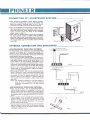
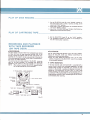
LINE VOLTAGE SELECTION AND FUSE
Switching Line Voltage Setting and Fuse
ln order to remove the fuse, turn the fuse cap located on the
Fig.
line voltage selector switch in the direction indicated by an
arrow. Then remove the fuse plug from the unit. Put the fuse
plug back so that the proper line voltage marking can be seen
through the cut in the edge of the plug.
Whenar'er the set position of the selector switch is changed,
check the rating of the fuse. A O.S-ampere fuse is to be used
for either 22OV or 240V operation and a 1-ampere fuse for any
of 1 lOV, 117V, or 130V operation. lf the rating of the fuse is
proper, install the fuse in the fuse cap.
.REPLACING OF FUSE
When the fuse is blown, remove the fuse cap and replace
the fuse with a new one.
@
-T
corN
FUSE CAP
Take off the fuse cap by turning it with a coin,
in the direction indicated by the arrow.
1
PIONEE.R
R MODEL SX.44O
FMSTEREo
MONO l^
FM 88 s s? 91 90 98 100 l0? t04 106 108
55 60 70 80 S0
100
l?0 140 160 x loKHz
TAPE
MON LOUDNESS
SPEAKER
AFF
!Hlrr.c
MHz
VOLUME
L __0_.R
B
I
g
6
11
12
t3
Fig.4
15 1617
2B 21 22 23
1g
1B
24
25
26 27
28
29 30 3t
32 33
Fig.5
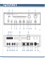
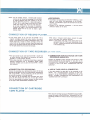
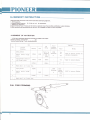
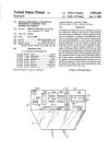
KNOBS AND SWITCHES ON FRONT PANEL
1. POWER SWITCH
Power is turned on when the s^ritch is rotated clockwise; turned
off when rotated counterclockwise. Operation of this switch also
turns on and off the power supplied to the AC OUTLET (3O)
When the s^,itch is set to the "A" position, the loudspeakers
connected to the SPEAKER SYSTEM A TERMINALS on the
rear panel of the SX-440 emit sound; when set to "8". those
connected to the SPEAKER SYSTEM B TERMINALS.
2. TUNING INDICATOR
9. BASS CONTROL
of the SX440.
located on the rear panel
When tuninq the radio receiver to an FM or AM broadcast
station, the TUNING KNOB (4) is adjusted so that the pointer of
this meter may deflect to the maximum.
3. FM STEREO INDICATOR
When the SX-2140 receivesan FM stereo program, this lamp lights.
4. TUNING KNOB
An AM or FM broadcasting station is tuned in. While observing
the pointer of the TUNING INDICATOR (2), set the knob for
the best receiving condition,
5. SELECTOR SWITCH
SX-440
AM . .
The
FM
Reception o{ monaural FM broadcasts
FM STEREO Automatically selective reception of stereo or
monaural FM broadcbsts
PHONO. . . . . Play of disk record
Connection of a record player having a crystal
AUX ,. .
or ceramic pickup, cartridge tape player, or
audio output of a TV receiver.
I
6. PHONES
Cord plug of a stereo headphone is inserted here for enjoying
stereo play without disturbing other people around. Loudspeakers
stop emitting sound then. For the stereo headphone, PIONEER's
Model SE-2P, SE-20, SE-30 or SE-50 is recommended.
. When a lonqer cord is required for the stereo headphone, use
PIONEER's Model JB-23 extension cord separately available.
When desiring to connect two stereo headphones,
PIONEER's Model JB-22
"Y"
use
cord separately available.
7. LOUDSPEAKER ON/OFF SWITCH
With this sruitch in the "ON" position, loudspeakers emit sound.
When the snritch lever is set to "OFF", loudspeakers stop
sounding, lt is convenient for using a headphone,
B. LOUDSPEAKER SELECTOR SWITCH
l
-\
B
(LEFT]
ffi .".o^r*
o
"o.,',o*
.
of this treble control knob is similar to that of the BASS
CONTROL KNOB (9) ,
12. TAPE MONITOR SWITCH
For ordinary record play or radio reception, keep thiss^ritch in
the "OFF" position.
Set the svvitch to "ON" only when playing back a tape by using
a tape recorder (or tape deck) or monitoring the recording
condition of such equipment. lf the switch is set to the "ON"
position when conducting disk record play or radio reception,
loudspeakers do not sound. Be careful in this respect.
13. LOUDNESS CONTOUR SWITCH
to the "ON" position while theSX-440
is operated at a low sound volume, both bass and treble are
boosted for easy listening. When the equipment is operated at
a high sound volume, it is recommended to keep the suritch in
the "oFF" position.
When the switch is set
14. VOLUME CONTROL
Fis.7
The loudspeaker sound volume increases
when this
it
knob is turned clockwise;
the knob is rotated
RIGHT CHANNEL
decreases when
both component knobs rotate together
to control the sound volumes of right
and left channels simultaneously, To
adjust the volume of either right or left
channel alone, hold one of the component knobs by one hand
and turn the other component knob by the other hand. lt is
convenient for balancing the sound volumes of both channels.
The front knob is for the left channel and the rear knob is for
IRIGHT)
mm
When playing a disk record or tape, or receiving a broadcast
program, keep this snritch in the "STEREO" position. Set the
saritch to "MONO" only when using a monaural record player
or tape recorder, or reproducing a tape on which monaural
recording is made,
by friction. When the knob is turned,
the right channel.
/ A:i;?"-'"Vq
I
10. TREBLE CONTROL
Use
counterclockwise, This double knob consists of two component knobs interlocked
nn
I " ooa't,o*
channels simu ltaneously.
11. MODE SWITCH
I
for one of the following operations:
Reception of AM broadcasts
is set
MONO
As this knob is turned clockwise, bass is boosted, as turned
counterclockwise, attenuated. The control is designed to give a
flat characteristic curve when the knob is set to the middle sf
the rotation range.
oThis knob controls the tone quality of both right and left
Fis. 6
TERMINALS AND CONNECTION ON REAR PANEL
15. FM ANTENNA TERMINALS
An FM
broadcast receiving antenna will be connected
terminals,
16. GROUND TERMINAL
to
these
1
Connect a ground conductor to this terminal for grounding the
SX- zl40
17. AM ANTENNA TERMINAL
This terminal is provided for connecting an external AM
broadcast receiving antenna.
most suitable FM antenna, AM antenna and
grounding, refer to the article "ANTENNA CONNECTION AND GROUNDING".
NOTE: For the
18. AM FERRITE ANTENNA
An AM broadcast receiving antenna accessory to the SX-440
When using the SX44O where the f ield intensity is high, reception cah be conducted simply by adjusting the direction of this
antenna without connecting an external antenna
ANTENNA TERMINAL (17).
to the AM
19. PROTECTIVE FUSES
These fuses protect transistors in the
SX-440
.When loudspeaker
terminals are short-circuited, or the SELECTOR (5) on the front
panel is operated while the SX-440 is used at a high sound
volume, one or both of the fuses may blown to protect power
transistors. When this occurs, replace the blown fuses with the
accessory 2-ampere fuses. The right-hand side fuse is for the left
channel; the left-hand side fuse is for the right channel.
20. MAGNETIC PHONO TERMINALS
25. LAPE
_ BECORDTNG / PLAYBACK
NECTOR (DIN TYPE}
CON_
Provided that the tape recorder (or tape deck) to be used has
a DIN-type tape recording/playback connector, connection for
recording and playback (and monitor) can be completed simply
by linking the tape recorder with the SX440 through the
recording/playback cord that is separately available. When this
connector is used, terminals (23) and l24l are not used,
26&27. SPEAKER SYSTEM A TERMINALS
Two speaker systems A and B can be connected to the SX44O ,
and they can be selectively used by operating the switch (8).
Connect the right channel loudspeaker of the firsl speaker
systems to terminals (26) and the left channel loudspeaker to
terminals (27).
28
&
29. SPEAKER SYSTEM B TERMINALS
When using two speaker systems, use these terminals (28) and
(29) for the second systems. Connect the loudspeaker for the
right channel to terminals (28) and those for the left channel
to terminals (29).
NOTE: For connection of loudspeakers to these terminals,
the plugs contained in the accessory bag must be used.
For correct loudspeaker connection, refer to the article
,,CONNECTION
OF LOUDSPEAKER SYSTEMS".
30. AC OUTLET ISWITCHED)
The power obtained from this AC outlet is turned ON and OFF
interlinked with the operation of POWER SWTTCH (1), A
maximum of 20O VA can be supplied to the record player or
Connect here the output cords of a record player equipped
with a magnetic cartridge. The upper jack is for the left channel;
the lower jack, for the right channel. When connecting a
monaural record player, use either one of the iacks.
31. AC OUTLET (UNSWITCHED)
21. AUXILIARY TERMINALS
32. LINE VOLTAGE SELECTOR AND FUSE
other equ ipment connected"
An AC outlet having a capacity of
is not interlinked with the operation
2O0 VA.This power outlet
of POWER SWITCH (1).
These jacks are used when connecting the output cords of a
record player equipped with a crystal or ceramic cartridge, or a
cartridge tape player. Also use these jacks for reproducing the
audio output of a TV receiver. The upper jack is for the left
channel; the lower jack, for the right channel.
This selector is used for setting the SX-44O to suit the line
22. GROUND TERMINAL
33. AC CORD
2
lf the record player or other equipment to be used with the
SX-440 has a ground conductor, connect it to this terminal.
23. TAPE MONITOR TERMINALS
to these jacks the playback output terminals (line
output) or monitor terminals of the tape recorder (or tape
deck) used with the SX-44O
Connect
24. TAPE RECORDING TERMINALS
to these jacks the recording input terminals (line input)
tape recorder (or tape deck). The signals outgoing from
these terminals cannot be adiusted with the VOLUME (14),
BASS (9) or TREBLE (1Ol controls.
NOTE: For correct connection to the TAPE MONITOR (23)
andTApE RECORDING l24l jacks, refer to the articte
,,CONNECTION
OF TAPE RECORDER"
Connect
of the
HOLDER
voltage to be supplied. lt also serves as a fuse holder. For the
selector setting and fuse replacement procedures, refer to the
article "LINE VOLTAGE SELECTTON AND FUSE". (page 1)
After correctly setting the LINE VOLTAGE SELECTOR (321,
connect this cord to an outlet of the commercial power line.
PIONEI.R
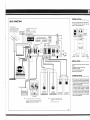
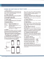
CONNECTION OF LOUDSPEAKER SYSTEMS
Fig. 8
. When connecting
loudspeakers, extract speaker connector
plug from the accessory bag and connect the speaker wire
l€ads to the plugs and illustrated below. Be sure to connect
the positive of the leads to the positive terminal of the plug.
.
When the loudspeakers are connected to the plugs. insert the
right channel speaker plug into the speaker system A terminal
socket (26) and the left channel speaker plug into the speaker
system A terminal socket (27). (Refer to the connection
diagram shown in page 2 .)
.When using two speaker systems, connect the wire leads of
the second speaker systems to speaker plugs as described
above, and insert the right channel speaker plug of this speaker
system into the speaker system B terminal socket (28) and the
left channel speaker plug into the speaker system B terminal
SPEAKER TERMINALS
ER
socket (29).
SPEAKER PLUG
ANTENNA CONNECTION AND GROUNDING
FM T'TYPE INDOOR ANTENNA
rFM BROADCAST RECEIVING ANTENNA:
The field strength of FM broadcast is much attenuated behind
mountains and buildings, and in ferroconcrete buildings. This
requires to use an FM antenna of different type depending on
the area and place where the SX44O will be used. Use the most
suitable antenna, referring to the following:
o Employ the T-type indoor antenna accessory to the SX440
when using the SX-440 within a wooden building near the FM
radio station. Connect the end of the vertical section of the
T-type antenna to the FM ANTENNA TERMINALS (15) as
.
shown in Fig. 9, and expand the horizontal section of the Ttype antenna. While actually receiving broadcast, determine the
direction of the horizontal section for the best radio reception
and fix it on a wall or other place. Refer to the article
"RECEPTION OF FM BROADCAST" reprding the determination of the antenna direction.
When using the SX-44O afar from the broadcasting station,
behind a mountain or within a ferroconcrete building, install
an FM radio antenna (or FM/TV common antenna) outdoors
and connect it to the FM antenna terminals (15). The FM
antenna is various in type, having 3 to 7 elements. Select the
most suitable antenna by consulting a nearby radio antenna
Fis. 9
,
FM OUTDOOR ANTENNA
sales store,
NOTE: The installation procedure of FM radio antenna is
similar to that of TV antennas. For details, followthe
instructions accompanying the FM radio antenna
purchased.
rAM BROADCAST RECEIVING ANTENNA:
. When using the SX440
near the broadcasting station or
inside a wooden building, it is unnecessary to install an AM
antenna. ln crch an area, set the direction of the AM FERRITE
ANTENNA for the best radio reception while actually listening
to broadcasts. Refer to the article "RECEPTION OF BROAD-
CAST".
good reception cannot be attained wen by properly adjusting the direction of the AM FERRITE ANTENNA, use the
accessory AM lead wire antenna. Connect one end of the
antenna to the AM ANTENNA TERMINAL ('17) and expand
the wire along a wall of the room.
lf good reception cannot be attained even when the acc€ssory
lead wire antenna is used, install an AM antenna outdoors.
Connect the lead-in wire of the outdoor antenna to the AM
ANTENNA TERMINAL (17).
. lf
.
Fig. 10
CII
NOTE: For the outdoor antenna, a standard AM broadcast
antenna can be formed by purchasing pVC wire from
an electric appliance shop and installing it 25 feet
(7.5 m) above the ground for a horizonial length of
50 feet (15 m), with a feeder line 30 feet (1O m) long.
These wire lengths may not be so price and may
be as long as allowed by the place of installation.
However, the height of the horizontal section of the
antenna should not be too low to attain a good
IGROUNDING:
o Groundingor non-grounding the GROUND TERMINAL 1 (16)
does not much affect the performance of the SX-440.
However, it is desirable to ground the terminal from the viewpoint of safety.
. Connect to the GROUND TERMINAL 1 (16) the ground
conductor leading to the earth.
antenna effect.
CONNECTION OF RECORD PLAYER
. lf the record player to be
used with the SX-440 has a
magnetic cartridge, connect the output cords of the record
player to the MAGNETIC PHOI\O TERMINALS (2O); if the
record player has a crystal or ceramic cartridge, connect the
output cords to the auxiliary terminals. lns€rt the output cord
plug for the left channel into the upper terminal jack, and that
for the right channel into the lower terminal jack.
CONNECTION OF TAPE RECORDER
. The tape recorder to
be used with the SX-44O should have
an output terminal (line output) for connection to external
amplifier, or a tape monitor terminal.
When using a monaural record player, connect its output
cord to the upper (left channel) terminal.
NOTE: lf the output cord plug of the record player to be
connected does not fit the input terininal jack of the
SX-2140 , replace the plug with the pin plug contained
in the accessory bag,
(OR TAPE DECK)
r CONNECTION FOR PLAYBACK
RECORDING MONITOR):
(OR TAPE
o When using a tape deck, the tape deck should have a recording/
playback preamplifier built in. PIONEER's Model T-500F
separately available can be used with the SX44O without
any problems.
Connect the playback output terminals (line output or tape
monitor terminals) of the tape recorder (or tape deck) to the
TAPE MONITOR TERMINALS (23). Tne connecting procedure
is similar to that of the above "CONNECTION FOR RE-
TCONNECTION FOR RECORDING:
r USE OF TAPE REC/P.B. CONNECTOR:
Connect the recording input terminals (line input) of the tape
recorder (or tape deck) to the TAPE RECORDING TERMINALS
(24l. of the SX-440 . For this connection, use the cords which
are normally accessory to the tape recorder.
The upper one of the recording input terminals (line input)
is for the left channel; the lower one, for the right channel.
When the tape recorder is monaural, connect its input terminal
to the upper TAPE RECORDING TERMINAL (24l. .
CORDING".
lf the tape recorder (or tape deck) to be connected to the
SX440 has a recording/playback connector of DIN type,
@nnect it to the TAPE REC/P.B. CONNECTOR (25) of the
SX-44O . Disregard "CONNECTION FOR RECORDING" and
,,CONNECTION FOR PLAYBACK'"
CONNECTION OF CARTRIDGE
TAPE PLAYER
When using the cartridge tape player {PIONEER's Model H-60E),
connect its output to the AUXILIARY TERMINALS (21). The
connecting procedure is similar to that for record player connec-
tion,
IPIONEER
RECEPTION OF BROADCAST
r BEFORE
TURNING ON THE POWER SWITCH
OF THE SX.44O, CHECK THE FOLLOWING:
VOLUME CONTROL KNOB (14) is set to "MtN".
TAPE MONITOR SWITCH (12) issetto "OFF".
MODE SWITCH (11) set to "STEREO".
SPEAKER ON/OFF SWITCH (7) is set to "ON".
(lf using a stereo headphone, set the s^/itch to "OFF").
r
RECEPTION OF FM BROADCAST:
1, SEt thE SELECTOR KNOb (5) tO thE "FM STEREO"
position.
2. While observing the pointer deflection of the TUNING
INDICATOR (2), tune the SX-440 to the desired station by
using the TUNING knob (4) . The best reception isattained
when the pointer of the TUNING INDICATOR (2) largely
deflects rightward. lf the tuned station is broadcasting a
stereo program, the STEREO INDICATOR (3) lights. With
the SE LECTOR knob (5) in this position, monaural
programs can also be received.
3. When the desired station is tuned in, gently turn
the
VOLUME CONTROL knob (141 clockwise. Ad.iust the
BASS CONTROL (9) and TREBLE CONTROL (10) for the
desired tone quality.
.When the SX-2140 is used very afar from the broadcasting
or external noise is intensive, the noise is supand better reception is attained by setting the
SELECTOR knob (5) to the "FM MONO" position.
station,
pressed
4.
When the knob is in this position, however, stereo programs
are received as monaural programs. (The stereo indicator is
unrelated although it lights.)
When good radio reception cannot be attained by the
above operating procedures 1 to 3. reconsider the antenna,
referring
to the article "ANTENNA
GROUNDING".
CONNECTION AND
TRECEPTION OF AM BROADCAST:
1. Set the SELECTOR knob (5) to the "AM" position.
2. While observing the pointer deflection of the TUNING
INDICATOR (2). tune the SX440 to the desired station by
using the TUNING knob (4). The best reception is attained
when the pointer of the TUNING INDICATOR (2) largely
deflects rightward.
3. When the desired station is tuned in, adjust the VOLUME
CONTROL (14), BASS CONTROL (9) and TREBLE CONTROL (10) for desired sound volume and tone quality.
4. When good radio reception cannot be attained, such as
speaker sound is noisy or inferior in tone quality by the
above operating procedures 1
referring
to 3, re+onsider the antenna,
to the article "ANTENNA CONNECTION
AND
GROUNDING". When the SX-440 is used very near the
broadcasting station, the field intensity is sometimes too
strong, resulting in low tone quality. lf this occurs, shorten or
remove the antenna connected to the AM antenna terminal
for the best radio reception.
OI
PLAY OF DISK RECORD
Set the SELECTOR knob (5) to the "PHONO" position. lf
the record player used a crystal or ceramic cartridge, set the
knob to the "AUX" position.
2. When using a monaural record player, set the MODE SWITCH
(11) to the "MONO" position.
3. Adjust the voLUME, BASS and TREBLE CONTROLS for
desired sound volume and tone quality.
1.
PLAY OF CARTRIDGE TAPE
1, Set the SELECTOR knob (b) to the ,,AUX', position.
succeeding procedure is similar to its counterpart of
the disk record player operation.
2. The
RECORDING AND PLAYBACK
WITH TAPE RECORDER
(oR TAPE DECK
IRECORDING:
The same signals as those emitted from loudspeakers can always
be taken out from the tape recording terminals (241 of the
SX-40 .Operate the selector knob (5) and mode switch (11)
according to the program source to be recorded, following the
instructions described in articles "RECEPTION OF B ROADCAST"
and "PLAY OF DISK RECORD"
The volume, bass and treble controls of the SX44O cannot be
used for the tape recording. The recording lwel should be
adjusted by the control of the tape recorder (or tape deck).
NOTE: When using a monaural tape recorder, signals of either
left or right channel only can be recorded.
3 HEADS.TYPE TAPE
RECORDER
I
PLAYBACK:
set the TAPE MONTTOR SWTTCH (12) to the ,'oN" position.
Adjust the VOLUME. BASS and TREBLE CONTROLS for
desired sound volume and tone quality.
.When the TAPE MONITOR SWTTCH (12) is in the "ON"
position, the position of the SELECTOR knob {5) is unrelated
to the playback operation.
r TAPE
MONITOR:
lf the
tape recorder used with the SX-44O is provided with a
monitor circuit, monitor can be effected regardless of the tape
recorder being two-head or three-head type. Connect the tape
recorder to the SX440 recording and playback terminals. By
setting the TAPE MONITOR (121 from "OFF" to "ON" while
making recording, the signals applied to the recording head can
be monitored if the tape recorder is of the two head system. lf a
three-head tape recorder is used, recorded signals can be monitored immediately after recording.
RECORDING
HEAD
PLAY BACK HEAD
ERASING
HEAD
LINE INPUT
TERMINAL
TAPE REC. TERMINAL
LINE OUTPUT TERMINAL
TAPE MONITOR
TERMINAL
TAPE
SPEAKER
SYSTEM
IV]ON
INPU
TERMINAL
MODE/ TAPE MON SWTTCH
Fig.'12
10
PTONEER
ALIGN
M
ENT INSTRUCTION
instruction with extreme care before attempting alignment.
Test Equipment.
1)Standard Signal Generator. 2) VTVM, DC, AC 3) Oscilloscope.
" Attention on Alignment,
1) Signal Generator lnput: Always use the minimum generator input that provides a satisfactory output indication.
2) When connecting the test equipment to the input, use a shielded wire that is as short as possible.
Please read these
*
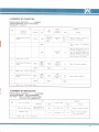
ALIGNMENT OF AM SECTION
* VTVM and oscilloscope should be connected in parallel at the output.
Position of Switch: SELECTOR
. . . AM
Volume Control Setting: Fully counterclockwise
i
nput
Eq u
C
on
i
pment
F
nections
req
uency
Level
Sweep generator
I
Antenna
terminal
Signal generator to antenna ter
minal through dummy
5
600kH
1,400k
Repeat steps
S
gnal
2 a"d i
z
5
0dB
30dB
C
of no
interference
as near as
600k
1,400k
Hz
on
iprnent
nections
generator
T
Itir
zot
Tzoa
H z
H
ust
T zas
z
600kH
Adjust
for
maximum sensitivity
sVmmetrical characteristics.
Adjust
for
maximum deflection.
CT
Ferrrte
z
Antenna terminal
(B
30d B
Antenna
(Adj
usting
core)
6
I,400k
5 and 6
Rema rks
Tzos
0sci lloscope
0scilloscope
Repeat steps
Adj
severa' times.
dummy
7
etting
535kHz
3
4
Eq u
Point
455kH z
dummy
2
S
Alrgnment
Output
Dial
Step
several times
DIAL CORD STRINGING
Hz
l.400k
H
z
CT zos
Adjust for maximum difldcction.
and
CDI
ALIGNMENT OF FM SECTION
SELECTOR
Position of Switch:
FM MONO
Volume Control Setting: Fully counterclockwise
Disconnect TP zoL from TP zoz
I
npul
0 utput
Dial
STEP
Eq ur
C
on
n
pment
F
ections
req
uency
S
Level
Eq ui
etting
C
of no
nterference
on
A
nectlons
Adjusl
Point
Sweep generator to FlVl antenna
term ina
r
10.7M H z
L
i
0dB
as near
as
Oscilloscope
I
zot, f
T
zo:,
Rema rk s
zoz
Adjust
Primary of
TP zot
87MHz
Check symmetry
c
Connect TP 2ar
Ia
5
,'J,tlilri'"""o'
'o
FM antenna
]
no,
8
:J:;il,:.".""'
5 and 6
,o
Fr\4
20dB
(400H z,
*.
H
z
0scii loscope
TP zo:
106MHz
Antenna
I
nor
20dB
(400H z,
r.
30"/"
steps 8 and 9 several
90MHz
T zaq
L2o4
Adjust
for maximum
deflection.
CT:o:
0sci lloscope
Adjust maximum
l'ri:,
TP zo:
)
106MHz
Repeat
characteristic
several times
9
10
90MHz
30%)
106M
Repeat steps
TP zo:
of
urve,
fP2a2
6
7
and
Adjust the primary core of Tzoa 56
that slope of straight portion of "S"
curve will become the steepest and
adjust the secondary core so that
the center of "S" curve wiil coinclde
with the center of the marker.
Oscilloscope
70dB
4
maximum sensitivity
T zoc
00dB
3
for
symmetrical characteristics.
2
I
lign ment
pmeni
defrection.
CT zor
l06MHz
CI
zoz
times.
ALIGNMENT OF MPX SECTION
Position of Switch: SELECTOR
. , FM STEREO
Volume Control
Setting: Fully
counterclockwise
lnput Signal: Main (L+R) 40.5kHzdeviation (602)
19 kHz Pilot 7.5 kHz deviation
(102)
I
STE P
Circuit
to
be
2
3
l9kHz and 38kHz
stages
on
7
and
nections
MPX Generator to
FIV Antenna terminal
Separation Control
Repeat steps
Alignment
Connect
C
I
npul
adjusted
S
ignal
l9kH
z
lorR
2
several times.
VTVI\4
Ad
AC VTVM
AC VTVM
TPzos
2 or
3
f
i
ust
zog
T zro
T zro
Rema rk s
Adlust for maximum
deflection
Adjust for mrnirnum deflection
of the other channel
PIONE.[.R
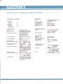
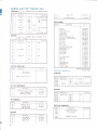
MODEL SX-44O TECHNIGAL SPECIFICATIONS
.
o FM SECTION
Circuitry
TRANSISTORS AND DIODES
Tuner Section
F,E.T.
Transistors
D iodes
Audio Section
Transistors
Diodes and etc.
1
1
Frequency Range
1
IHF UsableSensitivity
17
lmage Reiection
Signal-to-noise Ratio
20
6
Antenna lnPut
AUDIO SECTION
Circuitry
Music Power Output
Single ended push-pull
RMS Rated Power Output
4fl
MULTIPLEX SECTION
Circuitry
Time-snritching type demodu-
Channel Separation
automatic selection
35 dB (at 1 kHz.)
40wattstotal (lHF rating)
8,fl 33wattstotal (lHF rating)
4C}
15 watts per channel
(both channels driven)
8Cl 12 watts per channel
(both channels driven)
o
z (at lkqz
Harmonic Distortion
Less than 1
Frequency Response
output)
3dB, f rom 20 Hz to 70 kHz
lnputs and Audio Sensitivity
(for rated output)
rated
(overall)
30 Hz to 20 kHz (AUX)
MAG: better than 75 dB
AUX: better than 85 dB
MAGnetic PHONO: 3 mv.
TAPE MONITOR: 130 mv.
AUXiliary:
Output Terminals and Jacks
130 mv.
Speakers: 4to 16 ohms.Stereo
headphones jack. Simu ltaneous
tape Recording jacks, equ ipped
with TAPE MONITOR
sruitch.
Tape recording/plaYback jack
(DlN
Equalization Curve
Tone Controls (each channel)
standards)
PHONO:
RIAA
BASS: boost 13dB,cut 11dB
(at 50 Hz)
TREBLE:boost 9.5d8, cut
Loudness Contour
3 gang variable capacitor.
87 - 108 MHz.
2.SttV
55 dB (at 98 MHz.)
5O dB {lHF rating}
30O ohms (balanced)
.
.
Power Bandwidth
Hum & Noise (at rated output)
Front end using "F.E.T." and
10dB (at 10 kHz)
Switchable to ON-oFF. Boost
12 dB at 50 Hz, boost 6 dB at
1 0 kHz, with VOLUME control
set at - 40 dB
AM
FM mono/stereo
SECTION
Circuitry
Frequency Range
IHF
lator.
Usable Sensitivity
lmage Rejection
Antenna lnput
Superheterodyne
525
1605 kHz.
8pV
47 dB (at
Built
.1OO0 kHz.)
in ferrite loopstick
antenna
o PIOWER SUPPLY ETC,
Line Requirements
Dimensions
11O, 117 , 13O,22O,240 volts,
(wvitchable),
5O/6O Hz.8O watts (max.)
Overatt
15-15 I 16" I 4}5mm (width)
5-7 | 1 6" I
15'
139mm ( height)
/358mm (deothl
Without Package 17lbs. 7.7k9
With Package 20lbs.8 oz. 9.3k9
OI
CON
DITIONS
ENTLY
FREQU
M
ISTAKEN TO TROU BLES
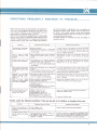
Noise: There are a variety of noises relating to the operation of
a hi-fi unit. These are generally divided into two types; (1) the
unit is faulty (a transistor or part is deteriorated) and (21 an
external source of noise gives noise to the unit.
When a hi-fi unit produces an unpleasant noise, it is often judged
that the unit is faulty, but statistical records indicate that the
majority of noises produced in a hi-f i acoustic units result from
external sources of noise. Due to the inherent high sensitivity
Symptom
Suspected Source
Continuous or intermittent
noise like
jijjij ot
zzzzzz,
o
o
oa
o
ID
in, hum is mixed in the
program
o
.9
o
o
cc
Hissing sound noise in AM
(medium wave) reception.
The frequency of an adjacent station
a
is
interfering with that of the station being
tuned in (1okHz beat interference).
. TV set is on in the same house where
the
Fleversing the llne plug may occasionally alleviate this
noise problem, Usually it is very difficult to eliminate
the noise.
lmpossible to remove such interference. lf the
such noise is in the TV set, increase the
between the TV set and receiver.
cause of
distance
receiver.
a
Reception of FM stereo
program contains more
noise than FM mono
a Note that the service area covered by an
FM stereo broadcast is about 50 %
that of a regular mono broadcast.
lncreasing FM input signal may alleviate this problem"
Use an exclusive FM outdoor antenna instead of the
Hum or
a Poor connection of shielded wire (a).
a Jack connection is loose. (b)
a Line cord or fluorescent lamp is near the
shielded wire, (c)
o Poor gyounding. (d)
a HAM transmitting station or TV transmitting station is near your house, (e)
Correct the conditions stated in (a), (b), (c) or (d).
ln case of (e), report it to an official activity.
. Stylus is worn out. (a)
. Record is worn out. (b)
. Dust adheres to stylus. (c)
.lmproper mounting of stylus. (d)
a Stylus pressure is not proper. (e)
. The TREBLE sound tevel is too high.
Check (a) through (e) and correct the condition,
Lower the TREBLE level,
buzz,
When
switched to radio reception,
the noise will disappear,
o
s
o-
c
3
house.
ln many cases, it is very difficult to remove the source
of noise. ln order to increase the radio input larger than
the noise level, set up a good outdoor antenna and
make a complete grounding.
Static noise in FM reception
(in particular, when automobiles run close to the
house).
.g
o
Diagonosis and Remedy
hou se.
proqram.
o
of Noise
a Poor fluoresent lamp, motor, or electric
heater may be used in house or near the
.
J
c
o
I
3
troubles of the unit.
a Flourescent lamp, motor, or thermostat
may be used in house or in the vicinitv
o
.!c
an appropriate corrective action.
The table includes the conditions that may be mistaken to
. Statics or listening.
of the
When a station is tuned
and the high fidelity in reproduction, the unit amplifies and
reproduces extraneous noises, however small, into definite output noise. lf your receiver produces a noise, check according
to the following table and trace out the source of noise for
Output tone quality is poor
and mixed with noise.
Treble is not clear.
White noises generated from automobile
engines.
a
R adio f requepcy sewing mach ine or welding machine being used near your house,
ln an area surrounded by hills or high buildings, the
FM input signals are very weak. Thus the noise limiter
in the circuit loses its function. Set up an outdoor FM
antenna having many reflector elements.
indoor T-antenna.
Lower the TREBLE level,
Further, watch the following conditions: These are also apt to be mistaken to troubles of the unit.
Symptom
Suspected Source
of Noise
Diagonosis and Remedv
Power is not turned on although the power switch is
set to ON.
o Fuse is blown. (a)
'
Check (a) and (b) and correct the condition.
ln playing a record, increasing the volume will cause
a Distance between the record plaver and
Change the distance or rearrange the installation positions of the unit and speakers. (lnstallinq the .ecord
plaver on a firm, solid stand may alleviate this problem.)
Do not eR+t€nce the BASS sound level excessively.
howling.
.
Line plug is
loo*.
(b)
the speakers is too short.
a
The place on which the record player or
speakers
is unstable.
trr
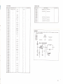
PARTS LIST OF THE SX-44O
0APACIT0RS tN
P:
pF lo%
TOLERANCE UNLESS OTHERWISE NOTED
ppF
Description
Symbol
Cr
Part
Toggi Switch
S6
No
DCI
43.O0
.4K\
3 -C
Line Voltage Selector
Se
Cz
Eiectrolytic
C:
Ceramic
Cs
35V
10v
l 000
100
1 80P
Ca
s42.O22.A
Sr
0.01
Cerami c
5
s11,O18-O
2.046.A
M I S CE
50v
LLAI{E (lUS
Ce
Cr
N4yl
ar
0.0 2
+
Part
Description
Symbol
zOaZ
No
Cg
Electrolytic
Cs
1
000
5
16V
1
-021
.C
AF Unit
w15- O73-A
Tuner Unit
Power Suppty Unit
w3 5.007.o
Front Ponel
Plustics Panel
M2t.267 -O
M2r.27 t.O
Wooden Case
Screw, to f ix Wooden Case
Dial Pulley, for Tuning Capacitor
Dial Pulley
B I I -022.8
M42.0 18,E
Dial Glass
Dial Pointer
A 33-O74.O
A 3 r,087,O
Foot
Mtt I -01 7.o
C ro
Ltl
C
C
Mylar
0.1
Ceramic
0.01
+ zoaz
50v
r:
i:
DCt.4K\
43.O03-O
BESI STt]HS
IN OHIVS,lO'.
K : KO
I\,4
Symbol
TOLERANCE UNLESS OTHERWISE NOTED
Mcr
Descriptlon
Part
Carbon Film
15K
No
%w
Knob,
Knob,
Knob,
Knob,
Knob,
2Vl
Pilot
Carbon Film
R
10
l .007.o
A12-131,O
Volume
(
Volume
L)
12.134-O
13.0 r 3,O
12.136.O
12 139.O
E22.O12.O
A
A
A
A
( R)
Selector
Tuni ng
Lamp
Pilot Lamp socket
100
Fuse
Fuse
R
41 ,002 ,B
E21.OO7.O
K
DI(]DE AIIt) TRAIISISTORS
I
Description
Part
Th
E
E 21
K7 2.OO7 .B
(Metal Cover M33-086-D
No
P0wtR
SD.tyz Diode
D,22A Thermister
Dr
21.004.O
,00s-o
K 92.006.O
K72.O21.8
K 93-003-B
IA
2A
Fuse Holder 2p
Head phone Jack
Connector 5p
Plug for Speaker
22
R
2-009.8
A9
Bass, Treble, Power
Fuse 0.5A
R
ymbo
M4
3-086,D
E22.Or5.O
,4w
R
S
tM3
Tuning tvleter
22K
0.5
w16.021-0
SUPPLY
SX-aa0(Fl Onty)
UiltT(yfl 6.021)
CAPACI Tt)RS
Thz
25D226 ot 2SD130 Transistor
Qr
Svmbol
Q:
Q:
Qr
C(]IL AIID TRAI{SF(lRi[
Symbo
DescIptt
I
Ll
Tr
Tz
on
Alvl Ferrite Loopstic Antenna
Power Transformer
l\,tatching Transf ormer
T:
Part
No
Electro lytic
C o4
Ceramic
f52
T6l
157-O
041 .O
VRz
250K dual, Volume
1 00K dual , Bass
VR:
100K dual, Treble
Part
R
01
R
02
03
o4
05
ca7 .021, -o
S:
S+
Ss
-2A%
Descriptio
Part No.
n
Carbon film
390
'1
0K
150
J.J\
DI(lBES A]ID TRAIISIST()RS
Symbol
Descri ptio n
D1 01
15337 Zener Diode
SD-1y,Diode
D102
nput Selector
Power Switch
Toggle Switch
114
22K
Dl03
I
15V
D.C 1.4KV c43-OO3-0
c 82.0 3 3,0
o10'1
Sz
+BA%
No
swrTct{Es
Sr
001
05
Symbol
R
Description
2?,v
10
100
RESI STt]RS
R
P(]TTIITI llM ETE RS
VRr
i00
r42.O22-ts
R
Symbol
Part No.
n
C 01
C 02
C 03
C
ERS
Descriptio
s 13.02 l ,B
s11.016,A
s42 002.A
4102
25C968Y Transistor
Part No.
TUr{tR
Ut'lrT(
w35-007)
ztz
Czt3
C
lvy la r
Cztt
CAPACIT{)RS
C275
C 276
+
C 277
C 2or
1op
I0.5p
C zoz
0.001
+ rooaz
C zos
0.01
C 278
RESI ST()RS
Czoc
C2o5
15p
C zoo
0.01
1op
C zoz
C zoe
1
t O.5p
+ rooali
-o
t 0.5p
R 201
00p
f: 0.5p
C zog
1p
Czro
0.01
carbon Film
1
00K
R zoz
R 203
+100
1tM
R 205
470
220
C2r2
2.2p
R 206
22K
Czr:
0.04
R zoz
Czr+
o.01
R 208
2.7K
Czrs
39Op
R2o9
10K
Rzro
i00
R
0
Czrr
t 0.5p
Czro
5p
C2!7
2p
C 218
o.04
Czrg
390p
C 220
3p
C22t
0.04
C zzz
Pol
+ 10042
-0
t0.5P
+ 100t%
o
33h
yst yrene
C 223
820p
Czz+
C
zzs
C
zza
El
ectrolytic
2.2
rami c
1op
Ce
C 227
9p
C 22a
1p
0.01
C zzs
t
0.5p
1op
C232
0.01
15K
R212
R 213
22K
1.2K
R2r4
r20
Rzrs
100
R
zre
680
R
2\7
63V
R 219
470
50v
R22a
100
R22\
1K
Rz2z
2.2K
6.8K
R 223
0
R224
0.5p
R zzs
+ t0094
R226
o
C233
R227
Cn4
Rzza
Cz:s
R229
C zso
R
C
zat
0.0 05
C 239
z4o
0.01
Czqr
39Op
9p
Czqz
0.005
0.04
C 243
Cz++
Cz+s
Electrol ytic
C2a6
Cer ami
c
0.04
Cz+a
0.0
t
0.5p
+ tooa,
zsz
0.0 05
R zse
R 239
50v
R 240
R
+ rooala
El
ect ro
Czso
z+:
5.6 K
27K
100
1
.5K
100
33
22K
68K
27K
100
R244
15K
R z+s
2.7K
220K
R z+o
o
z+t
47K
R 24e
R
Czs+
I yti c
z+r
Rz+z
0.01
C 253
z:o
63V
R
390p
z:a
Rztt
-o
zso
z:s
39K
R
i
Czsr
C
15K
R 233
R 235
C24s
C
z:o
R232
R
2.2
560p
C247
C
2.7K
22K
R 231
C 23s
C
10
I.2K
+ 100
t
Rzrr
R 21s
Czzo
C23i
zo4
2.2,
63V
R24s
10
16V
R 250
R251
1.5K
15K
4.7 K
100
zsz
220
C 251
Cerami c
0.01
50v
C zse
Electrol ytic
100
16V
R
63V
R 253
I2K
50v
R 254
a2K
C zss
C260
Polystyrene
680p
C26r
R
zss
470
C262
R
zss
3.9K
C
zaz
C 264
Electrolyti
c
lVylar
47
0.01
16V
R257
15K
50v
R
zse
39K
0.004
C265
R 2s9
Czoo
Polystyrene
C267
Electrolytic
33
C zog
Polystyrene
41 Op
Ceog
Electrol ytic
R
Pol ystyrene
33
80p
16V
Czto
50v
R 26a
C2t1
Myl ar
47 Op
1
o.o2
R
zoo
16V
R
zor
50v
R 262
zo:
R 265
680
1.2K
68
5.6K
100
1.5K
33K
2091
Is
R zoe
Carbon Film
AUD|0 UiltT (rvl5.073)
33K
68K
Rzo;
CAPACITORS
R 268
Rzos
R
Symbol
6.8K
z;o
c301
Rz;r
c303
c304
c305
c306
c307
Al{D TRAilStST0RS
Symbol
Descrptton
Part
No
D zoz
c31
c312
E
SD46R Diode
c314
I S188 Diode
c31 5
c31 6
D zoo
D 207
I S85 Diode
D zoe
I
D 209
Sl88
Dzl
*r,l^,
I
SI88
c32l
U
c329
c330
Q :os
25CB39 Tronsislor
UJJJ
2SCB7A
c334
c335
c336
c337
Qzrr
Tronsistor
COILS AND TRAIISF(]RMERS
L202
FtV RF Coit
RF Choke Coil
Lzo+
Lzor
Part
No
T
22-O15.O
T2 1.01 5 0
I24.O2a-O
T2 3.036.A
T75 005.O
T 7 5,004-0
FIV IFT
T7 3.O25.O
lzoi
T7 5.006.O
Tu or
T zoz
r
7
3-O,26.O
T zo:
f
zoq
T2o5
AIM OSC Coii
T74-006,0
T43 006.0
T zoa
AIM IFT
r7 r o,24.0
T
zot
I72
Tzoe
9KHz Transformer
T zog
1
Tzro
38KHz ,
c339
c340
c341
c342
c343
FIV OSC Coil
Choke Coil
L zoo
50v
|"
25V
)47
3V
50v
o;)
Electro
"
"
lytic
(Non polar)
(Non polar)
3,.3
25V
:9
10v
4,!
3V
c332
Q zog
Q zro
q
JZO
2SC43O Transistor
2SC838 Transistor
FM ANT CoiI
Ir
l^'^
I J.J
o:,
A
Q zot
L20l
25V
0.0068
c325
c326
Q zoa
L zo:
Mylar
c323
3SK"22 FET
2SC43O Transistor
2SC460 Transistor
Descriptton
L,n
|"o oo1
c321
aaa
Symbol
59v
,,
)
aQt)
Diode
Q zo:
C)212
o1
c320
2ri
Q zos
Electrolytic
c319
D2L3
Dztq
Dzrs
Dzro
10v
I
c31 8
OA79 Diode
SD46R Diode
D2i2
10
I
c317
Diode
D2ro
Q zoz
I
lectro I yt i c
c313
D 2oa
D 205
Q zo:
1
50v
10005
c30B
D 203
D
I
ioo,
2?,v
"-"
I
Mv,:*
c309
Q zor
Part No
aa
ectro yti c
c31 0
I S188 Diode
D 20l
I
c302
27K
Rztz
0l00ts
Description
E
T7
0I8.O
5.002,O
T75.O03-A
??
Mica
,]
I
tlectrolytic
,I
nrfi""
Electrolvtic
Mica
"
I
,990
25V
'l
47
50v
3V
]
3990
l
220
25V
1op
50v
I
)
1
?9v
RESI STt)RS
Symbol
I
R
30',I
R302
R303
R304
R305
R306
R307
R308
R309
R31 0
R31 1
IRAI{SISTORS
Description
Part No.
Carbon film
1,r
'100K
R31
50K
'1
2SC8l1 BL Transistor
Part No
o302
o303
o304
2SC870 BL Transistor
o307
o30B
0309
25C734 R,,Transistor
03'10
59K
031',I
25C734,P, Transisto r
4312
3
I
Descri ptio n
o30'r
o306
390
1K
4
5
6
7
8
Symbol
o305
R312
R31
R31
R31
R31
R31
R31
114
031 3
Q314
25,4561 P Transistor
2.2K
330K
15K
R320
R321
5.6K
R322
4.7K
N JJJ
330K
R324
R325
R326
R321
R328
R
59K
4l,K
329
1,r
331
R332
R333
diagram and parts list of this receiver has been
changed as follows.
R330
R
NOTE
o The circuit
15K
R245
R262
2.2K
4.7K
0209
0210
o211
2SC838
C279
Ceramic
15P
Tra nsistor
(add ition
)
h .1J4
R335
R336
R337
R338
R339
R340
R34
1
3.9 K
12K
220K
,?,*
R342
R343
6.8 K
R344
4.lK
R345
R346
R347
R348
F349
R350
4lo
150
1K
R35'l
R352
R353
R354
R355
R356
R357
R358
R359
R360
68K
4
!,K
150
2?o
R361
R362
R363
R364
R365
R366
R367
22
2?o
'1
5K
,l
18
|nPIONEER
o
G
o
o
o
o
F
z
lr|
E
f
=
=
F
tl)
I
F
G)
E,
D
(J
(J
o
UJ
F
z
t
o-
G)
r\
o
I
ro
3
F
f=
o
o
3
ta)
N
I
o
!
=
jo
1;+-<:t::-Ls
-
oo
"J*!:
ro
,rrx o o
,o-i.i,er"
iin ."T? "
" "-lr:-;$*
*:.;l_-""tT="
:?
1
,'t";F*r1,1_--':Jr"
;:3
I [email protected]
I
I if6 :+I" T Jlj: rJi6
!; "l;l_l?1't l
i'l= luf'f
i,lu,i,J
-rrf
" nl " "F _[
l=t' r+@1'tu'*"
d
oo
^I.,?rJo
--J:T.
r _il<
f:. .:
oai
.
9::
.s,9,
,g,,ci
o.o
q,9
oo
ao,
oq
:
oo
o.o
o.o
00
'00
oo.
oo
oo
oo
oo
o9
oq
oo
QO
oo
e
(\
I
o
CO
C1o5 001
o---lF----€
Rro.r
.SD-ly 9--AAF
Dro3
4.|--o
croc
D,o,olo' €
o__++---o
ioK
o----lr* s;
-yfA-
er
oo
ffi
"--doo
z
F
=.
oo
OI
o
6
2*Z
'l
-l-
e
=&:
DT;
O
d+
Fro-oril
-
ao€o------AAH-Qiso 9$.E
BA,
- o-\t-/
oo
oo -
sD-ty
Rros
CO
Rrot
o--A /------o e--MlH
3'3K
p t5o Rror
f
o.
f
och
E
5
o
o-
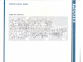
IfPIONEE.R
PARTS LAYOUT (Top View)
LI MW FERRITE ANTENNA
ANTENNA
gzbs=gzo+=
irn,l-ol
t=--.l l-l
tr] Ft ?*
W f E"o'39:@,
I t:l
J_
rzos
I o-l
t-"-l
L2o7
2scB38 T2l0
zrrgQ6zsa
o,zscato
TUNER
':o:
f
2a5cf 2o2 Cf zo4 CI 2ol
_:^u o
ururr(w:s-ooz
)
OQ212
POWER SUPPLY UNIT
(wr602t)
2SD226
or130
tA" o
',',f;'tgt
2SD226or13O
;;,"rz
r.,r
o
o 9^
"
e'3t'
;1,':'d:'
o
QIr2sAs6l
Q3O8
2SC/3/
2SCz3a 296s76 Q307
)56870
LEFT
25D226ort 30
RIGHT
AF UNIT
2SD226ot130
033
2SC 87 r
2sc870
oDt
'
(W15-073)
@
PI ONEER ELE,ETRONIE trURPORATIUN
15-5, 4-Chome, 0hmori-nishi, Ohta.ku, Tokyo, Japan
PIONEER ELEcrRoNlcs u.s.A.
coRpoRATroN
140 Smith St., Farmingdate, 1.1., N.y. 11735, U.S.A.
Printed in Japan
<69C02E04T>
I
I
eroNeen ELEcrRoNtc(EURopE)AG.
5g, forctr Strasse,8032 Zurich. Switzertand
<R12-O24-B>