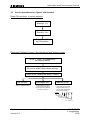
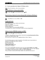
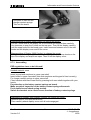
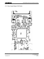
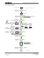
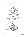
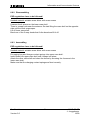
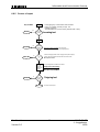
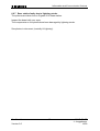
1
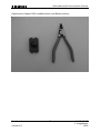
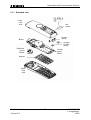
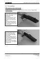
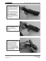
Information and Communication Products Service Manual Gigaset 3010 base station, Gigaset 3000 Classic handset, Gigaset 3000 Comfort handset Level 2.5 Confidential Version 2.0 1 ICM D CC ST J. Junggebauer 12/00 Information and Communication Products 1 Table of contents 1 TABLE OF CONTENTS .............................................................................................................................2 2 ADDITIONAL FEATURES AND DIFFERENCES TO GIGASET 2000 ..............................................3 2.1 3 DECT-SPECIFIC DETAILS ............................................................................................................................3 PROCEDURES ............................................................................................................................................4 3.1 3.2 3.3 SERVICE PROCEDURES FOR GIGASET 3000 CLASSIC ...................................................................................4 SERVICE PROCEDURES FOR GIGASET 3000 COMFORT .................................................................................5 SERVICE PROCEDURES FOR GIGASET 3010 BASE STATION ..........................................................................6 4 INFO STICKER ...........................................................................................................................................8 5 FAULT CODES............................................................................................................................................9 6 FAULT DIAGNOSIS AND ELIMINATION ..........................................................................................10 6.1 FUNCTIONAL TEST....................................................................................................................................10 6.2 RECOGNITION OF TYPICAL CUSTOMER PROBLEMS ....................................................................................12 6.3 CHECK OF COMPLETE SYSTEM WITH FAULT DESCRIPTION OF CUSTOMER ..................................................16 6.4 CHECK OF COMPLETE SYSTEM WITHOUT FAULT DESCRIPTION OF CUSTOMER............................................16 6.5 CHECK OF COMPONENT WITH FAULT DESCRIPTION OF CUSTOMER ............................................................16 6.6 CHECK OF COMPONENT WITHOUT FAULT DESCRIPTION OF CUSTOMER ......................................................16 6.7 REPAIR OF MOBILE UNIT GIGASET 3000 CLASSIC AND COMFORT .............................................................16 6.7.1 Exploded view ................................................................................................................................18 6.7.2 Disassembling ................................................................................................................................19 6.7.3 Assembling .....................................................................................................................................21 6.7.4 Board Layout Gigaset 3000 Classic ..............................................................................................22 6.7.5 Board Layout Gigaset 3000 Comfort.............................................................................................23 6.7.6 Course of repair .............................................................................................................................24 6.7.7 Mobile unit faulty due to humidity .................................................................................................25 6.7.8 No function.....................................................................................................................................26 6.7.9 Charging problems ........................................................................................................................27 6.7.10 SLR (microphone-path faulty)........................................................................................................28 6.7.11 RLR (earphone-path faulty) ...........................................................................................................29 6.8 REPAIR OF BASESTATION GIGASET 3010 ..................................................................................................30 6.8.1 Exploded view ................................................................................................................................30 6.8.2 Disassembling ................................................................................................................................31 6.8.3 Assembling .....................................................................................................................................31 6.8.4 Board Layout Gigaset 3010 (German version)..............................................................................32 6.8.5 Course of repair .............................................................................................................................33 6.8.6 Charging problems ........................................................................................................................34 6.8.7 Base station faulty due to lightning stroke .....................................................................................35 Confidential Version 2.0 2 ICM D CC ST J. Junggebauer 12/00 Information and Communication Products 2 Additional features and differences to Gigaset 2000 3000 Classic: - Improved user interface by soft-keys - Improved standby time up to: - Improved time for phone in use up to: - Call by call support - Crescendo ringing tone 100 h (NiCd) 10 h (NiCd) 220 h (NiMh 1500 mAh) 20 h (NiMh 1500 mAh) 3000 Comfort: - Handsfree possible by putting the mobile unit on the table in an upright position - Headset not supported - Call by call support - Radio Signal Strength Indicator - Key for telephone book - Standby time up to: 70 h (NiCd) 150 h (NiMh 1500 mAh) - Time for phone in use up to: 7 h (NiCd) 15 h (NiMh 1500 mAh) 3010 Base station: - CLIP-function - No LEDs for charging or on/off-hook - Caller-list for incoming or missed calls up to 30 entries (with time and date) - Listening in with a second mobile unit possible - Crescendo ringing tone 2.1 DECT-specific details Number of channels: Radio frequency range: Duplex method: Channel grid: Bit rate: Modulation: Voice coding: Confidential Version 2.0 120 1880 MHz to 1900 MHz (altered for certain countries) Time-division multiplexing, 10 ms frame length 1728 kHz 1152 kBit/s GFSK ADPCM (32 kBit/s) 3 ICM D CC ST J. Junggebauer 12/00 Information and Communication Products 3 Procedures This chapter shows the hidden service procedures for Gigaset 3000 Classic, 3000 Comfort and 3010 base station. Note: The service procedures are confidential. 3.1 Service procedures for Gigaset 3000 Classic Note: Press On-hook-key after every procedure. PIN-Reset to factory default (0000): 1, #, OK, , R, #, R, OK, 0, OK Reset to factory defaults (if unknown PIN, first PIN-Reset): This is no service-procedure (see user manual). 1, 8, OK, 0, 0, 0, 0, OK, 0, OK SW-Version (number in the middle (above 2. arrow) e.g. 16)): 1, #, OK, , R, #, R, OK, 1, OK ROM Checksum: 1, #, OK, , R, #, R, OK, 4, OK Displaytest: Press 1, 4 and 7 simultaneously and hold down while you switch on. With every key you press you alter the display test screen. Confidential Version 2.0 4 ICM D CC ST J. Junggebauer 12/00 Information and Communication Products 3.2 Service procedures for Gigaset 3000 Comfort Reset PIN and reset to factory defaults: select “Settings“, o.k. select “Security“, o.k. Enter “ R * # R “ as PIN number, Displaytest, Software-Version, Speechpath test and Metering mode: press 1, 4 and 7 simultaneously and keep pressed switch on and keep pressed until Handset Service is visible, then release all keys press 46395 (displaytest autom. visible) SW-Version, Read out software version. Speechpath test, Metering mode, Switch a direct loop from microphone to earphone (check the path by blowing into the microphone). Press “o.k.” to tick it and press menu key to switch off the handset. Now you can see radio parameters during normal usage *** *** example: 98 - 9 - 04 - 096 - 100 RX - Level Frequency (0...9) Time slot (0...11) Base station code bit error rate 100 = 100% o. k. Confidential Version 2.0 5 ICM D CC ST J. Junggebauer 12/00 Information and Communication Products 3.3 Service procedures for Gigaset 3010 base station Note: Press On-hook-key after every procedure. System-PIN-Reset to factory default (0000): 4, #, OK, , R, #, R, OK, 8, #, 9, OK Reset to factory defaults (if unknown System-PIN, first System-PIN-Reset): This is no service-procedure (see user manual). 3, #, OK, 0, 0, 0, 0, OK, 0, OK Fundamental reset: Disconnect mains. Press paging key on base station and hold down. Plug in AC- adapter. Hold key pressed for 25 seconds. Release paging key. The base station is now set to factory defaults. The system-PIN is reset to 0000 and all mobile units are deregistered. Software Version, EEPROM checksum and RFPI: 4, #, OK, , R, #, R, OK, OK A negative acknowledge tone is audible. Scroll with the arrow-downwards softkey until you reach 80 and press OK. With each key you press you are toggling between these 3 figures. On the following page you get a description of the hidden service procedures to change the following base station settings: DP-puls-pause-ratio Earth connection time Ringing identification Cradle switch identification Pause after occupancy First enter the procedure described on the next page until 3 dashes are visible. To change the settings you have to enter a 18 digit number when you see 3 dashes on the display. After entering this number you have to press O.K. Then you have to disconnect the base station from mains and reconnect it. Confidential Version 2.0 6 ICM D CC ST J. Junggebauer 12/00 Information and Communication Products The following 18 digit numbers are valid for SW-Version 01.015 – 01.019. First enter this procedure (3 dashes must be visible in the display): 4, #, OK, , R, #, R, OK, 18-digit no. , OK After entering the number don’t forget to confirm with o.k. and disconnect mains shortly. 18 digit numbers: - DP-puls-pause-ratio: 1,5/1: 070183392056126569 2/1: 070183392081725544 − Earth connection time: 450ms: 070183382057511350 1200ms: 070183382083110327 700ms: 070183382108709300 - Ringing identification: 23-54 Hz: 070183412064021874 15-75Hz: 070183411654405474 programmable: 070183412883254610 - Cradle switch identification: 800ms: 070183381654429366 2000ms: 070183382883245702 - Pause after occupancy: 5,5 s: 070183412057519330 11 s: 070183412083120355 7 s: 070183412108717280 4 s: 070183412134318305 Confidential Version 2.0 7 ICM D CC ST J. Junggebauer 12/00 Information and Communication Products 4 Info sticker S30852-S1301-B101 ............... CT/KN These are the 2 important numbers on the info sticker. The first number shows the type of the phone. Example: S30 means new component S36 means Swap component 852 means Gigaset family S1301 means 3010 family (S910 for 900; S911 for 1010) The following 2 characters indicate the country. B1 means Siemens (Germany (Classic handset also other countries)). C1 Austria C4 Australia ..... The following character shows you the variant. Euro-PTT-Version, Base with Classic-/ Comfort handset... The last character indicates the colour. The second number indicates the date of production. CT stands for Bocholt. The next character shows the year of production. L = 1999 The last character shows the month of production. 1-9 = January to September O = October N = November D = December Confidential Version 2.0 8 ICM D CC ST J. Junggebauer 12/00 Information and Communication Products 5 Fault codes Code D1 D2 D3 D4 D7 D9 D 11 D 12 D 13 D 14 D 15 D 16 D 18 D 19 D 20 D 25 D 26 D 28 D44 A04 A27 Symptom No key function No ringing function Charging problems Display problems Breaking off calls Poor call quality (humming, noises) No outgoing call possible No registration/ no call setup Answering machine problems Problems with use of „hands-free“ Range too short Mechanical fault Miscellaneous SLR (microphone-path faulty) RLR (earpiece-path faulty) No failure found No function Diverse procedures programmed wrong AC-Adapter faulty Stand-by time/ battery problems Keypad faulty Confidential Version 2.0 9 N 10 N 11 N12 N 13 N 17 N 34 N 37 N 38 N 39 Cause Not soldered Cold soldered Electric fault Mechanic fault Missing component Dirty component Loose component Humidity damage Lightning stroke damage ICM D CC ST J. Junggebauer 12/00 Information and Communication Products 6 Fault diagnosis and elimination There are different faults that could appear. Not all incoming components or systems have to be faulty. The customer could have problems with the operation of the phone or could have placed it close to a device (PC...) that affects it. So you won’t identify a fault. It could also happen, that there is a loose connection in the phone (due to a cold soldering joint or something else). So the fault won’t appear each time you test the phone. There are different possibilities to test a phone depending on the information you got with the phone. 6.1 Functional Test There is an incoming and an outgoing test. The difference between them is that in the outgoing test you make a reset on the component after testing in case of swap (to deregister, reset PIN and set to factory defaults). The steps for the mobile unit refer to Gigaset 3000 Classic. Outgoing test: 1) Displaytest 3000 Classic: Mobile unit is switched off. Press 1, 4 and 7 simultaneous and hold down while switching on. Press any key to alter pattern. 2) Charging-test: Mobile unit is switched off. Put mobile unit into charging cradle. One segment of the battery display has to start blinking automatically when putting in. 3) Make a fundamental reset on the base station you want to test in case of swap: Disconnect mains. Press paging key on base station and hold down. Plug in AC- adapter. Hold key pressed for 25 seconds. Release paging key. The base station is now set to factory defaults. The system code is set to 0000 and all mobile units are deregistered. 4) Reset mobile unit to factory defaults in case of swap: 1, 8, OK, 0, 0, 0, 0, OK, 0, OK Confidential Version 2.0 10 ICM D CC ST J. Junggebauer 12/00 Information and Communication Products The mobile unit is now set to factory defaults (if PIN not =0000, first reset PIN). 5) Register mobile unit at base station: Press paging key on base station and hold down until beep starts. INT, , 1 (for base 1), System-Code (default: 0000), OK Wait until display shows you the free internal numbers. Confirm the desired internal number by pressing it. 6) There are 2 possibilities of testing the fundamental functions of the telephone: This is depending on the size of the LSO (number of incoming telephones). 1) Test with PBX (private branch exchange): a) Ringer test b) Dialling test c) Audible test of telephone in send direction (SLR) d) Audible test of telephone in receive direction (RLR) with the help of a second phone connected to the PBX. 2) - 7) 8) Test with telephone tester (WPG 1000): Ringer test DC resistance and isolation resistance Testing the dial information (DTMF (dual tone multifrequency dialling)) Testing the dial information (DP (dial pulsing)) Testing the flash hookswitch (signal key) Audible test of telephone in send direction (SLR) Audible test of telephone in receive direction (RLR) Reset base station (fundamental reset). Reset mobile unit to factory default. Incoming test: Confidential Version 2.0 only step 1 to 6 11 ICM D CC ST J. Junggebauer 12/00 Information and Communication Products 6.2 Recognition of typical customer problems This chapter shows the incoming department which fault code refers to which problem and which component is faulty. Some problems concerning the mobile unit (not possible to switch on; not possible to register; acoustic problems; charging problems ...) could be caused by humidity. So you will have to open the mobile unit (opening tool) and look for tracks of a humidity damage. Many problems concerning the base station could be caused by lightning stroke. So you will have to open the base station and look for tracks of a lightning stroke. Problem 1: The customer can‘t hear any telephone conversation partner during a call (or hears his speach at a low volume). When he blows into the microphone he can‘t hear his noises on the earpiece. Fault code: D 20 (RLR) Faulty component: Mobile unit When he blows into the microphone he can hear his noises on the earpiece. Fault code: D 20 (RLR) Faulty component: Base station Problem 2: All telephone conversation partners of the customer can‘t hear him during a call (or hear his speach at a low volume). When he blows into the microphone he can‘t hear his noises on the earpiece. Fault code: D 19 (SLR) Faulty component: Mobile unit When he blows into the microphone he can hear his noises on the earpiece. Fault code: D 19 (SLR) Faulty component: Base station Problem 3: The customer can‘t switch on his mobile unit. Æ Check the batteries and insert new ones for testing. Fault code: D 26 (no function) Faulty component: Mobile unit Confidential Version 2.0 12 ICM D CC ST J. Junggebauer 12/00 Information and Communication Products Problem 4: The customer can’t call or/ and can’t be called (no ringing). His mobile unit seems to work properly. When he presses the paging key there is no beep audible. Æ Check the AC-adapter first. Fault code: D 1 (no key function), D44 (AC-Adapter faulty) or D 11 (if only no outgoing call possible and AC-Adapter ok) Faulty component: AC-adapter or base station Problem 5: The segment of the battery display doesn’t start blinking when charging. Æ Check the batteries and insert new ones for testing. Æ Check the charging craddle (golden device). Fault code: D 3 (charging problems (if batteries are o.k.)) Faulty component: batteries or mobile unit or base station/ charging craddle Problem 6: The mobile unit or the base station doesn’t ring. Æ Check AC-adapter (if base station) or batteries and insert new ones for testing. Fault code: D 2 (no ringing function) Faulty component: Mobile unit or base staion Problem 7: Some characters are not visible or only sometimes visible. Fault code: D 4 (Display problems) Faulty component: Mobile unit Problem 8: The customer has caused visible mechanical damages. Fault code: D 16 Faulty component: Mobile unit or base station Problem 9: Confidential Version 2.0 13 ICM D CC ST J. Junggebauer 12/00 Information and Communication Products There can be various possibilties. Example: The customer claims that he can’t set up an outgoing call or the ringing volume is too low. Check the programmed procedures (see chapter Procedures). Fault code: D 28 (diverse procedures programmed wrong) Faulty component: Mobile unit or base station Problem 10: The customer claims that the connection breaks off if he tries to go away from the base station. Inside buildings the range should be up to 50 m, but if there are ferroconcrete-walls between mobile unit and base station the radio contact can break off due to absorbtion and reflections at the wall. Test the range by picking up the handset and going away from the base station for the desired distance (no walls between). If there is still a problem check which component is faulty by using a golden device. Fault code: D 15 (Range too short) Faulty component: Mobile unit or base station Problem 11: The connection breaks off sometimes during a call. Æ Check the batteries and insert new ones for testing. If they are o.k. and there is still a problem use a golden device to find out which component is faulty. Fault code: D 7 (Breaking off calls) Faulty component: Mobile unit or base station Problem 12: The customer claims that there is a poor call quality or that there are noises audible during a call (humming...). Check the call quality. If the customer was right take a golden device to identify the faulty component. Fault code: D 9 (Poor call quality (hummung, noises)) Faulty component: Mobile unit or base station Problem 13: The customer claims that his mobile unit doesn’t ring (incoming call) or he claims that he can’t set up an outgoing call. The mobile unit doesn’t ring when pressing the paging key. The character referring to the radio connection is blinking. Confidential 14 ICM D CC ST J. Junggebauer Version 2.0 12/00 Information and Communication Products Æ 3000 Classic: In standby, just pressSET, INT Now you see the numbers of basestations the handset is registered on. Æ 3000 Comfort: Press menu and select base settings. If there is no tick on any base station the handset is not registered. Æ The mobile unit has no connection or has lost the connection to the base station. Try to register the mobile unit to the base station. Fault code: D 12 (no registration/ no call setup) Faulty component: Mobile unit or base station Problem 14: The customer claims that there is no function when pressing any key. There could also be problems when pressing some keys. Fault code: D 1 (No key function) Faulty component: Mobile unit Confidential Version 2.0 15 ICM D CC ST J. Junggebauer 12/00 Information and Communication Products 6.3 Check of complete system with fault description of customer Try to reconstruct the fault using the description of the customer. Check the batteries and the AC-adapter. Find out whether the customer has programmed something wrong by checking the procedures concerned. If that was not successful make an incoming test. If there is a fault try to find out which component is faulty by registering at a golden device and testing again (deregister it from the golden device after testing). Register swap component to customer component. 6.4 Check of complete system without fault description of customer Check the batteries and the AC-adapter if existing. Make an incoming test. If there is a fault try to find out which component is faulty by registering at a golden device and testing again (deregister it from the golden device after testing). Register swap component to customer component. 6.5 Check of component with fault description of customer Register component to golden device. Try to reconstruct the fault using the description of the customer. Check the batteries (handset) or the AC-adapter (base station). Find out whether the customer has programmed something wrong by checking the procedures concerned. If that was not successful make an incoming test using the steps 1 (if mobile unit), 2, and 6 of the outgoing test. Deregister customer device from golden device after testing. 6.6 Check of component without fault description of customer Register component to golden device. Check the batteries (handset) or the AC-adapter (base station). Make an incoming test. Deregister customer device from golden device after testing. 6.7 Repair of mobile unit Gigaset 3000 Classic and Comfort Special equipment: Confidential Version 2.0 16 ICM D CC ST J. Junggebauer 12/00 Information and Communication Products Opening-tool Gigaset 3000 (modified pliers) with Battery-dummy: Confidential Version 2.0 17 ICM D CC ST J. Junggebauer 12/00 Information and Communication Products 6.7.1 Exploded view Lower case shell Info sticker Contact spring Board Charger Contact spring Earphone/ spring contact Contact spring board Keypad Upper case shell Confidential Version 2.0 18 ICM D CC ST J. Junggebauer 12/00 Information and Communication Products 6.7.2 Disassembling ESD regulations have to be followed ! Needed material: Opening-tool Gigaset 3000 and battery dummy Gigaset 3000 Insert battery dummy first to prevent that charger contact springs bend while dismantling. Insert opening tool in belt clip hole and press pliers together until snap hooks open. Hold the handset with the other hand as described in the picture and press case shells together. Turn handset upside down and insert pliers in the 2. belt clip hole and press pliers together until snap hooks open. Hold the handset with the other hand as described in the picture and press case shells together. Make sure that the battery dummy is still in the battery compartment. Confidential Version 2.0 19 ICM D CC ST J. Junggebauer 12/00 Information and Communication Products Insert pliers between the case shells near the display and press pliers together until remaining snap hooks open. Hold the handset with the other hand as described in the picture and press case shells slightly together. Make sure that the battery dummy is still in the battery compartment. Turn handset upside down and do the same as described on the picture above. Make sure that the battery dummy is still fixed and lift off lower case shell as described in the picture. Hold the board with the other hand while lifting the case shell. Make sure that you don’t bend the battery contact springs! Confidential Version 2.0 20 ICM D CC ST J. Junggebauer 12/00 Information and Communication Products Use pliers to take out the charger contact springs. Take out the board. Disassembling of Display 3000 Classic (to change the cover): Cut the 2 studs that fix the display foil on the board and remove them carefully. Use tweezers to snap the 2 hooks on the top open. Then lift the display carefully until the snap hooks for the board open. Insert tweezers between one of the side hooks and the display cover and lift the cover. Disassembling of Display 3000 Comfort (to change the cover): This procedure is very simple. Insert tweezers between the 2 snap hooks on the top of the display and snap them open. Then lift off the display cover. 6.7.3 Assembling ESD regulations have to be followed ! Needed material: none Insert keypad and earphone in upper case shell. Insert board in upper case shell (note that earphone and keypad is fixed correctly). Fix charger contact springs in upper case shell. Close handset with lower case shell by pressing both case shells together with your hands. Pay attention on the battery contact springs on board. Make an optical inspection of the battery contact springs afterwards. Put in batteries and check spring tension. Switch the handset on to check correct function of battery contact springs. Assembling of Display 3000 Classic/ Comfort (to change the cover): Remove dust on LCD with pressure air. Then carefully attach display cover until all hooks engaged. Confidential Version 2.0 21 ICM D CC ST J. Junggebauer 12/00 Information and Communication Products 6.7.4 Board Layout Gigaset 3000 Classic Confidential Version 2.0 22 ICM D CC ST J. Junggebauer 12/00 Information and Communication Products 6.7.5 Board Layout Gigaset 3000 Comfort Confidential Version 2.0 23 ICM D CC ST J. Junggebauer 12/00 Information and Communication Products 6.7.6 Course of repair Handset remains registered device o. k. Reset yes SET, 1, 8, OK, 0, 0, 0, 0, OK, 0, OK device works properly ? Incoming test no Open device Scrap device yes Damage due to humidity ? Use opening tool D 43 white/ green depositions on soldering points often under display or beside microphone --> see chapter 5.7.7 mobile unit faulty due to humidity no no no Level 3 - Rep. Possible to switch on ? use testhousing Fuse faulty ? no Possible to switch on ? yes D 26 yes D3 insert new fuse possible to charge ? yes are contact springs springy ? no yes no Level 3 - Rep. SLRtest o. k. ? use testhousing D 19 insert new microphone no SLRtest o. k. ? are contacts oxidized ? no yes change them change them function test after assembling yes no Level 3 - Rep. RLRtest o. k. ? yes use testhousing insert new earphone no RLRtest o. k. ? D 20 yes yes no Level 3 - Rep. does it ring ? D2 yes no Level 3 - Rep. Display o. k. ? D4 yes use a new display cover keypad and springs always use a new housing display cover and keypad could be reused for personalized repair when o.k. yes no Level 3 - Rep. device works properly ? outgoing test yes device is o. k. Confidential Version 2.0 24 Put device into Swap-Pool ICM D CC ST J. Junggebauer 12/00 Information and Communication Products 6.7.7 Mobile unit faulty due to humidity Pictures: Gigaset 1000S, 2000S and 2000C Note: Most humidity damages on the front side are beside the microphone, under the keypad (bottom portion) and regarding The Comfort handset under the display (lift it up). Look at all electronic components on the back side. Do not open the RFPart. Remaining flux on the component side could look similar to a humidity damage (white deposits) but it will disappear when heating it up with a hot air blower. Recommendation: When you are not sure whether deposit is humidity or flux, heat the area concerned with a hot air blower and scrap the unit only when deposit doesn’t disappear. See photos in document „humidity & Lightning“. Confidential Version 2.0 25 ICM D CC ST J. Junggebauer 12/00 Information and Communication Products 6.7.8 No function Fault code: D 26 Affected unit: Gigaset 3000 Classic/ Comfort Components: Fuse F2 (Classic)/ F1 (Comfort) (1A) Needed equipment: Multimeter Soldering iron Working material: Desolder wick Solder Diagnosis: Check the fuse with a multimeter. Repair by component exchange: If the fuse is faulty desolder it and clean solder pads with desoldering wick afterwards. Solder a new fuse. Test: Try to switch the device on. Confidential Version 2.0 26 ICM D CC ST J. Junggebauer 12/00 Information and Communication Products 6.7.9 Charging problems Fault code: D 3 Affected unit: Gigaset 3010 base station Components: charger contact springs charging joints/ pads Needed equipment: Soldering iron Glass fibre pen Working material: Desolder wick Solder Diagnosis: The battery segment on the handset display doesn’t start blinking when charging. Inspect the charging joints/ pads looking for small black holes on the surface. Repair by cleaning/ soldering joint/ pad and component exchange: Roughen the surface with a glass fibre pen. Solder the charging joints so that there is a thin deposit of new solder on the joints. Suck away surplus solder with desolder wick. Roughen the surface with a glass fibre pen. Use new contact springs. Test: Take a testhousing and put in new charger contact springs. Check if battery segment on display starts blinking when charging. Confidential Version 2.0 27 ICM D CC ST J. Junggebauer 12/00 Information and Communication Products 6.7.10 SLR (microphone-path faulty) Fault code: D 19 Affected unit: Gigaset 3000 Classic/ Comfort Components: Microphone Needed equipment: Soldering iron Working material: Desolder wick Solder Diagnosis: The diaphragm of the microphone is affected by humidity or nicotine with increasing age or the microphone could be electrically faulty. There will be a higher attenuation when measuring SLR (sending loudness rating). In most cases the microphone is defective. Repair by component exchange: Remove the microphone by desoldering the 2 solder joints. You can also heat up both pins simultaneously with a broad soldering iron tip and turn the board upside down, letting the microphone fall out. Clean pads with desoldering wick and replace it by a new component afterwards. Attention: Avoid excessive heat (2 seconds maximum)! Test: Put the repaired board in a testhousing. Make a sidetone check by blowing into the microphone and checking the volume of the noise on the earphone. If there is a telephone tester with acoustic testhead make a SLR-test and check whether the attenuation is o.k.. Confidential Version 2.0 28 ICM D CC ST J. Junggebauer 12/00 Information and Communication Products 6.7.11 RLR (earphone-path faulty) Fault code: D 20 Affected unit: Gigaset 3000 Classic/ Comfort Components: Earphone Needed equipment: Multimeter Working material: none Diagnosis: The diaphragm of the earphone could be affected by deposits with increasing age. There will be a higher attenuation when measuring RLR (receiving loudness rating). In most cases the earphone is defective. If there is no noise audible on the earphone when making a sidetone check it’s also possible that the wire of the coil is cut off. Check the resistance of the coil with a multimeter. It must be about 150 ohms. If you measure a nearly infinitely high resistance, the wire may be cut off. Repair by component exchange: Use new earphone capsule. Test: Put the repaired board in a testhousing. Make a sidetone check by blowing into the microphone and checking the volume of the noise on the earphone. If there is a telephone tester with acoustic testhead make a RLR-test and check whether the attenuation is o.k.. Confidential Version 2.0 29 ICM D CC ST J. Junggebauer 12/00 Information and Communication Products 6.8 Repair of basestation Gigaset 3010 6.8.1 Exploded view Screws Lower case shell Antenna Board Paging button Charger contact springs Upper case shell Confidential Version 2.0 30 ICM D CC ST J. Junggebauer 12/00 Information and Communication Products 6.8.2 Disassembling ESD regulations have to be followed ! Needed material: suitable screw driver with cross recess Unscrew the 4 screws on the lower case shell. There is a snap hook near the antenna. So start lifting the case shell on the opposite side until the hook snaps open. Lift off lower case shell. Bend one of the 2 snap hooks that fix the board and lift it off. 6.8.3 Assembling ESD regulations have to be followed ! Needed material: suitable screw driver with cross recess Put paging key and charger contact springs into upper case shell. Insert board into upper case shell until it snaps into place. Attach the other case shell and close the device by screwing the 4 screws in the lower case shell. Make sure that the charging contact springs are fixed correctly. Confidential Version 2.0 31 ICM D CC ST J. Junggebauer 12/00 Information and Communication Products 6.8.4 Board Layout Gigaset 3010 (German version) Confidential Version 2.0 32 ICM D CC ST J. Junggebauer 12/00 Information and Communication Products 6.8.5 Course of repair Reset Only for SWAP device o. k. yes Press paging key on base station and hold down. Plug in AC- adapter. Hold key for appr. 25 s. Release paging key. The base station is now set to factory defaults (PIN = 0000). device works properly ? Incoming test no Open device Scrap device yes no Level 3 - Rep. Damage due to lightning stroke ? no o.k. ? black soot or chipped components near the sockets --> see chapter “base station faulty due to lightning stroke” If there are charging problems check charging contact pads and springs If faulty, repair and assemble the base station and check function. Was repair successful? yes use a new paging key, antenna and springs no Level 3 - Rep. device works properly ? If not yet happened, assemble the base station. always use a new housing New parts only for SWAP Outgoing test yes device is o. k. Confidential Version 2.0 Put device into Swap-Pool 33 ICM D CC ST J. Junggebauer 12/00 Information and Communication Products 6.8.6 Charging problems Fault code: D 3 Affected unit: Gigaset 3010 base station Components: charger contact springs charging joints/ pads Needed equipment: Soldering iron Glass fibre pen Working material: Desolder wick Solder Diagnosis: The battery segment on the handset display doesn’t start blinking when charging. Inspect the charging joints/ pads looking for small black holes on the surface. Repair by cleaning/ soldering joint/ pad and component exchange: Roughen the surface with a glass fibre pen. Solder the charging joints so that there is a thin deposit of new solder on the joints. Suck away surplus solder with desolder wick. Roughen the surface with a glass fibre pen. Use new contact springs. Test: Take a testhousing and put in new charger contact springs. Check if battery segment on display starts blinking when charging. Confidential Version 2.0 34 ICM D CC ST J. Junggebauer 12/00 Information and Communication Products 6.8.7 Base station faulty due to lightning stroke The pictures are taken from a Gigaset 2010 base station. Inspect the board with your eyes. The components on the photos have been damaged by lightning stroke. See photos in document „humidity & Lightning“. Confidential Version 2.0 35 ICM D CC ST J. Junggebauer 12/00