1
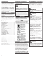
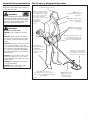
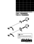
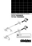
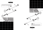
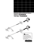
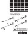
ENGLISH SHINDAIWA OWNER’S/OPERATOR’S MANUAL T260 GRASS TRIMMER T260X GRASS TRIMMER LE260 LAWN EDGER C260 BRUSHCUTTER T260 LE260 T260X C260 WARNING! Minimize the risk of injury to yourself and others! Read this manual and familiarize yourself with the contents. Always wear eye and hearing protection when operating this unit. Part Number 62710-94310 Rev. 8/05 Introduction Attention Statements General Safety Instructions The Shindaiwa 260-series hand held power equipment has been designed and built to deliver superior performance and reliability without compromise to quality, comfort, safety, or durability. Throughout this manual are special “Attention Statements”. Work Safely Shindaiwa’s high-performance engines represent the leading edge of 2-cycle engine technology, delivering exceptionally high power with remarkably low displacement and weight. As an owner/operator, you’ll soon discover for yourself why Shindaiwa is simply in a class by itself! IMPORTANT! The information contained in this manual describes units available at the time of publication. WARNING! A statement preceded by the triangular attention symbol and the word “WARNING” contains information that should be acted upon to prevent serious bodily injury. CAUTION! A statement preceded by the word “CAUTION” contains information that should be acted upon to avoid damaging the unit. Shindaiwa Inc. reserves the right to make changes to products without prior notice, and without obligation, to make alterations to units previously manufactured. IMPORTANT! A statement preceded by the word “IMPORTANT” is one that possesses special significance. Contents NOTE: A statement preceded by the word “NOTE” contains information that is handy to know and may make your job easier. PAGE Attention Statements .................................. 2 Safety Information....................................... 2 Safety Labels ................................................ 4 Product Description .................................... 6 Specifications ............................................... 6 Assembly ...................................................... 7 Installing Cutting Attachments ................ 11 Engine Fuel ............................................... 15 Read and follow this� operators manual.� Failure to do so could� result in serious injury. Wear eye and hearing� protection at all times� during the operation � of this unit. Keep bystanders� at least 50 feet (15 m)� away during operation. � Starting the Engine ................................... 16 Stopping The Engine ................................ 16 Beware of thrown or � ricocheted objects. Adjusting Engine Idle ............................... 17 Checking Unit Condition ......................... 17 Shoulder Strap ........................................... 17 Cutting Grass (trimmer head) ................ 18 Using a Brushcutter Blade ...................... 19 Using the Edger ........................................ 20 Maintenance .............................................. 21 Muffler Service ......................................... 23 Long Term Storage ................................... 24 Blade Sharpening ...................................... 24 Troubleshooting Guide ............................ 25 Emission System Warranty ...................... 26 2 Do not operate this unit� with a blade unless the� unit is equipped with a� handlebar. Always wear a harness� when operating this unit� with a blade. A harness� is also recommended when � using trimmer line.� � If unit is used as a � brushcutter, beware of� blade thrust. A jammed� blade can cause the unit� to jerk suddenly and may� cause the operator to� lose control of the unit.� � � IMPORTANT! The operational procedures described in this manual are intended to help you get the most from your unit, and to protect you and others from harm. These procedures are guidelines for safe operation under most conditions, and are not intended to replace any safety rules and/or laws that may be in force in your area. If you have questions regarding your 260series unit, or if you do not understand something in this manual, your Shindaiwa dealer will be glad to assist you. You may also contact Shindaiwa, Inc. at the address printed on the back of this Manual. Trimmers and brushcutter operate at very high speeds and can do serious damage or injury if they are misused or abused. Never allow a person without training or instruction to operate this unit! WARNING! Never make unauthorized attachment installations. WARNING! Use Good Judgment NEVER operate the engine when transporting the unit. NEVER operate the engine indoors! Make sure there is always good ventilation. Fumes from engine exhaust can cause serious injury or death. ALWAYS use the proper cutting tool for the job. ALWAYS stop the unit immediately if it suddenly begins to vibrate or shake. Inspect for broken, missing or improperly installed parts or attachments. NEVER extend trimming line beyond the length specified for your unit. ALWAYS keep the unit as clean as practical. Keep it free of loose vegetation, mud, etc. ALWAYS hold the unit firmly with both hands when cutting or trimming, and maintain control at all times. ALWAYS keep the handles clean. ALWAYS disconnect the spark plug wire before performing any maintenance work. ALWAYS if a blade should bind fast in a cut, shut off the engine immediately. Push the branch or tree to ease the bind and free the blade. WARNING! The engine exhaust from this product contains chemicals known to the State of California to cause cancer, birth defects or other reproductive harm. General Safety Instructions The Properly Equipped Operator Stay Alert Wear hearing protection devices and a broad-brimmed hat or helmet. You must be physically and mentally fit to operate this unit safely. WARNING! Never operate power equipment of any kind if you are tired or if you are under the influence of alcohol, drugs, medication or any other substance that could affect your ability or judgement. Wear close-fitting clothing to protect legs and arms. Gloves offer added protection and are strongly recommended. Do not wear clothing or jewelry that could get caught in machinery or underbrush. NEVER wear shorts! Always wear a harness when operating a unit equipped with a blade. Always operate with both hands firmly gripping the unit. WARNING! Minimize the Risk of Fire NEVER smoke or light fires near the unit. When operating with a blade, make sure the handle is positioned to provide you with maximum protection from contacting the blade. ALWAYS stop the engine and allow it to cool before refueling. Avoid overfilling and wipe off any fuel that may have spilled. ALWAYS inspect the unit for fuel leaks before each use. During each refill, check that no fuel leaks from around the fuel cap and/or fuel tank. If fuel leaks are evident, stop using the unit immediately. Fuel leaks must be repaired before using the unit. Always wear eye protection such as goggles or safety glasses. Keep a proper footing and do not overreach— maintain your balance at all times during operation. ALWAYS move the unit to a place well away from a fuel storage area or other readily flammable materials before starting the engine. NEVER place flammable material close to the engine muffler. NEVER run the engine without the spark arrester screen in place. Wear appropriate footwear (non-skid boots or shoes): do not wear open-toed shoes or sandals. Never work barefooted! Figure 1 Keep away from the rotating trimming line or blade at all times, and never lift a moving attachment above waist-high. Always make sure the appropriate cutting attachment shield is correctly installed. 3 Safety Labels This label indicates the minimum distance between front handle and rear grip per ANSI B175.3. T260 T260X IMPORTANT! Safety and Operation Information Labels: Make sure all information labels are undamaged and readable. Immediately replace damaged or missing information labels. New labels are available from your local authorized Shindaiwa dealer. Read Operator's Manual Protect eyes and hearing Keep bystanders at least 50 ft. away C260 Use handlebar when operating with a blade Wear harness when operating with a blade Beware of blade thrust LE260 Do not operate under influence of alcohol, drugs or medication 61843 Figure 2 4 Be Aware of the Working Environment (all units) Avoid long-term operation in very hot or very cold weather. Make sure bystanders or observers outside the 50-foot “danger zone” wear eye protection. Reduce the risk of bystanders being struck by flying debris. Make sure no one is within 50 feet (15 meters)—that’s about 16 paces—of an operating attachment. 50 FEET Be extremely careful of slippery terrain, especially during rainy weather. If contact is made with a hard object, stop the engine and inspect the cutting attachment for damage. Always make sure the appropriate cutting attachment shield is correctly installed. Beware of a coasting blade. A coasting blade can injure while it continues to spin after the throttle trigger is released or after the engine is stopped. When operating in rocky terrain or near electric wires or fences, use extreme caution to avoid contacting such items with the cutting attachment. Be constantly alert for objects and debris that could be thrown either from the rotating cutting attachment or bounced from a hard surface. Figure 3 5 Product Description Using the accompanying illustrations as a guide, familiarize yourself with your unit and its components. Understanding your unit helps ensure top performance, long service life, and safer operation. T260/T260X GRASS TRIMMER Spark Plug Handle Outer Tube WARNING! Do not make unauthorized modifications or alterations to any of these units or their components. Grip Ignition Switch Gearcase Barrier 260X Only Prior to Assembly Cutting Attachment Shield Before assembling, make sure you have all the components required for a complete unit: Fuel Tank Tank Protector Throttle Trigger LE260 LAWN EDGER Spark Plug Handle Ignition Grip Switch Engine assembly Outer tube assembly Line Cutter (T260/T260X) Cutting attachment shield Correct operator’s handle (see pages 7-9) Edger Blade Depth Adjustment Spark Plug Throttle Trigger Fuel Tank Handlebar Cutting Attachment Shield Fuel Tank Cylinder Cover Gearcase Carefully inspect all components for damage. IMPORTANT: The terms “left,” “left-hand,” and “LH”: “right,” “right-hand,” and “RH”; “front” and “rear” refer to directions as viewed by the operator during normal operation of this product. Tank Protector Ignition Switch Cutting Attachment Shield Cutting attachment (trimmer head or brushcutter blade) Kit containing debris shield mounting bracket and hardware, operator’s handle mounting bracket and hardware, this manual and tool kit for routine maintenance. Tool kits vary by model and may include a hex wrench, spark-plug/ screwdriver combination wrench, and spanner. Outer Tube Outer Tube Tank Protector C260 BRUSHCUTTER Brushcutter Blade Figure 4 Specifications T260/T260X Dry Weight (less attachments) ............ 5.0 kg/11.0 lb. LE260 Dry Weight (less attachments) ..................... 5.6 kg/12.3 lb. C260 Dry Weight (less attachments)......................... 5.2 kg/11.5 lb. Engine Model .............................................................Shindaiwa S260 Engine Type ..............................2-cycle, vertical-cylinder, air-cooled Bore x Stroke........................................... 32 x 30 mm/1.26 x 1.18 in. Displacement .......................................................... 24.1 cc/1.5 cu. in. Maximum Power Output ..........1.2 hp/0.9 kW @ 7500 RPM (min-1) Fuel/Oil Ratio ..................... 50:1 with Shindaiwa 2-cycle Mixing Oil Fuel Tank Capacity ..................................................... 600 cc/20.3 oz. Carburetor Type........................................ TK-DPN, diaphragm-type Ignition ................................... Fully electronic, transistor-controlled Specifications are subject to change without notice. 6 Spark Plug.................................................................. Champion CJ8Y (for EMC compliance use NGK BMR6A) Air Filter ..................................Non-reversible flocked filter element Starting Method ......................................................................... Recoil Stopping Method.............................................................. Slide switch Transmission Type ............................. Automatic, centrifugal-clutch w/bevel gear EPA Emission Compliance Period* ................................ Category A * The EPA emission compliance referred to on the emission compliance label located on the engine, indicates the number of operating hours for which the engine has been shown to meet Federal emission requirements. Category C = 50 hours (Moderate), B = 125 hours (Intermediate) and A = 300 hours (Extended). Assembly: Driveshaft/Powerhead All Models Connect the Outer Tube to the Powerhead. Spark Plug Clamp must fit next to line on outer-tube decal 1. Place the powerhead on a clean, flat surface, spark plug facing up. 2. Use the 4 mm Tube Clamp hex wrench to loosen the tube clamp screw. Powerhead T260/T260X LE260 Mainshaft Decal C260 Brushcutter 3. Slide the outer tube into the tube clamp until the tube bottoms. If installation is difficult, Figure 5 Hex Wrench rotate the outer tube or gearcase output shaft slightly until you feel the mainshaft splines engage with the powerhead. 4. Position the outer tube so that the gearcase output shaft is facing down (opposite the spark plug). Clamp Outer Tube Clamp Screw Throttle Assembly Figure 6 C260 — Slide the outer tube into the powerhead until the installation decal aligns with the tube clamp. T260/T260X/LE260 — Slide the outer tube into the powerhead until the throttle grip just contacts the tube clamp. Tube Clamp 5. Tighten the clamp screw firmly. CAUTION! Do not force the outer tube into the powerhead! Excessive force can damage the outer tube and mainshaft. Assembly: Handle T260 Connect the Handle to the Outer Tube. Socket-head Cap Screw 1. Position the handle on the outer tube forward of Handle Positioning Label as shown in Figure 7. 2. Install the mounting bracket with the socket head cap screws. Tighten the screws finger-tight ONLY at this time. Handle 3. Locate the handle in the best position for operator comfort (usually about 10 inches ahead of the throttle housing). 4. Secure the handle by alternately tightening the four socket-head screws in a diagonal or “crisscross” fashion. Mounting Bracket Outer Tube Trigger Housing Figure 7 Handle Positioning Label 7 Barrier Bar and Hanger Assembly Connect the Handle to the Outer Tube. Socket-head Caps Screws Handle 1. Remove the four socket-head cap screws on the handle and remove the handle and mounting bracket. Throttle Assembly 2. Position the handle on the outer tube forward of Handle Positioning Label as shown in Figure 8. Nut 3. Install the barrier bar with the sockethead cap screws and nuts. Tighten the screws finger-tight ONLY at this time. 4. Locate the handle in the best position for operator comfort (usually about 10 inches ahead of the throttle housing). Outer Tube Bolt 5. Secure the handle by alternately tightening the four socket-head screws in a diagonal or “criss-cross” fashion. Hanger 6. Position the hanger on the outer tube between the handle and throttle assembly. See Figure 8. 7. Secure the hanger with the nut and bolt as shown in Figure 8. Handle Positioning Label Barrier Bar Figure 8 Nuts Assembly: Handle LE260 Connect the Handle to the Outer Tube. Handle Trigger Assembly 1. Remove both screws from the handle. 2. While spreading the handle at the mounting hole, position the handle on the outer tube as shown. 3. Reinstall the two mounting screws in the handle, but do not tighten them at this time. Hex Nut NOTE: Hex Nut The handle is recessed to receive the hex nuts. Mounting Screw Washer 4. Locate the handle at the best position for operator comfort (usually about 10 inches ahead of the throttle lever). 26049 5. Secure the handle by tightening the knob at the handle base. Washer Outer Tube Adjustment Knob Figure 9 8 Assembly: Throttle Linkage and Ignition Leads T260/T260X/LE260 Install the Throttle Cable (T260/ T260X/LE260) 1. Loosen and remove the throttle lever clamp screw “A”. Throttle Cable 2. Extend the throttle lever. 3. Starting from the powerhead, push the throttle cable through the handgrip until it appears at the throttle assembly. 4. Insert the throttle cable end into the socket on the throttle lever. 5. Retract the throttle lever to its original position. Nut 6. Replace and tighten the throttle lever clamp screw “A”. Throttle Cable 26005 Red Ignition Wire Extended Throttle Lever 7. Using finger pressure only, connect the red and black ignition wires onto the connectors on the powerhead (see the inset). Clamp Screw “A” Insert throttle end into the socket Black Ignition Wire Connector Figure 11 Connector Assembly: Handle C260 Assemble the Handlebar Handle Positioning Label 1. Position the handle over the outer tube forward of Handle Positioning Label as shown in Figure 10. The handlegrips must face “up,” with the throttle lever to the right-hand side as shown in Figure 10. Rubber Mount Rubber Mount Handlebar Outer Tube Cable Tube Figure 10 Socket-head Cap Screw Mounting Bracket 2. Attach the handle mounting bracket from below using the two socket-head cap screws, washers, and lock washers. Tighten both screws FINGER TIGHT ONLY at this time. 3. Locate the handle in the best position for operator comfort (usually about 5 inches ahead of the harness loop.) If necessary, reposition the aluminum collar between the handlebar bracket and outer tube. IMPORTANT! The aluminum collar must be installed between the handlebar bracket and outer tube! If the aluminum collar is omitted or is improperly installed, the handlebar bracket cannot be properly secured. 4. Use the hex wrench to securely tighten both handlebar cap screws. 5. Working from the handlebar toward the powerhead, route the ribbed throttle cable tube through the two rubber mounts on the outer tube. 9 Assembly: Throttle Linkage and Ignition Leads C260 Install the Throttle Cable (C260) 1. Loosen and remove the throttle lever clamp screw “A”, and slide the throttle assembly about 1-inch away from the handgrip. Throttle Assembly About 1 inch 2. Extend the throttle lever (inset). Clamp Screw “A” Nut 3. Push the throttle cable and switch wires through the handgrip until it appears at the throttle assembly. Handgrip 4. Insert the throttle cable end into the socket on the throttle lever. 5. Retract the throttle lever to its original position. 6. Using finger pressure only, gently push the red and black ignition wires onto the connectors underneath the throttle assembly Throttle Cable and Switch Wires Insert ignition wires onto connectors (not color coded) 7. Slide the throttle assembly back to its original position, and then replace and tighten the throttle lever clamp screw “A”. Throttle Lever (shown extended) Insert Throttle Cable End Figure 12 10 Handlebar not shown for clarity Assembly: Cutting Attachment Shield T260/T260X/C260 SocketHead Cap Screw C260 T260/T260X Bolt Outer Tube Upper Clamp Cutting Attachment Shield Bracket Shim Shim Clamp Screw Nuts Shim Line Cutter Shim 23105 Figure 13 Retaining Nut Cutting Attachment Shield Mounting Plate Install the Cutting Attachment Shield T260/T260X/C260. 1. Insert the cutting attachment shield between the outer tube and the cutting attachment shield mounting plate. See Figure 13. Bracket NOTE: It may be necessary to loosen the retaining nut and clamp screw to adjust cutting attachment shield mounting plate. 2. Fit the two shims and the bracket over the outer tube and loosely install the four socket-head cap screws. See Figure 13. 3. Tighten the four socket-head cap screws to secure the cutting attachment shield. Nut Cutting Attachment Shield Hex Screws Figure 13A Cutting Attachment Shield WARNING! NEVER operate the unit without the cutting attachment shield installed and tightly secured! Hook Receiver Sub-Shield C260. (when trimmer head is in use) 1. Attach the shield extension to the cutting attachment shield. Sub-shield WARNING! NEVER use this machine without sub-shield when using a trimmer head. Hook CAUTION! Make sure the sub-shield is completely hooked at the hook receiver. CAUTION! Make sure the clamp screw and retaining nut are securely tightened before tightening the four socket-head cap screws. To Change Position of Line Cutter. The line cutter can be positioned in 2 positions to obtain different line length for cutting. 1. Remove the 2 hex screws with a 4 mm hex wrench. See Figure 13A. 2. Rotate line cutter. See Figure 13A. 3. Reinstall the two hex screws and tighten them securely. WARNING! The line cutter is very sharp. Wear gloves to protect your hands when handling. NOTE: Be careful to not lose the 2 nuts in the cutting attachment shield, they are not captured. 11 Assembly: Cutting Attachment Shield LE260 Mount the Cutting Attachment Shield on the Gearcase. 1. Remove the shaft bolt, bolt guard, holder A and holder B from the gearcase. Cutting Attachment Shield Bolt Guard 2. Align the cutting attachment shield assembly with the gearcase as shown, and then fit the shield onto the matching flange on the gearcase. 23029 Gearcase Flange Holder A The LE260 is intended for right-handed operation only! When correctly assembled, the cutting attachment shield and shaft must be oriented as shown. 4. Install a washer and nut on each of the three screws assembled in Step 3, then firmly tighten each nut. IMPORTANT! The three hex-head screws must be firmly tightened before installing and tightening the nuts. Mount the Edger Blade 1. Remove the plastic protector sleeve from the gearcase output shaft, and fit the holder A onto the shaft. 12 Holder B Nut CAUTION! 3. Install the hex-head screws and washers, then use the hex wrench to firmly tighten all three screws. Shaft Bolt Edger Blade Spring Washer 23030 Figure 14 Hex-head screws and washers 2. Mount the edger blade and holder B onto the shaft, and then install the bolt guard and shaft bolt (turn bolt counterclockwise to install). 3. Align the hole in blade holder A with the matching hole in the gearcase, and then use the hex wrench to temporarily lock the gearshaft as shown. 4. Use the combination wrench to firmly tighten the shaft bolt. Remove the hex wrench. 23031 Figure 15 Lock the shaft WARNING! The LE260 is designed for use with a single blade only! Never operate the LE260 without the cutting attachment shield installed and tightly secured! The LE260 Edger should now be completely assembled. Assembly: Trimmer Head T260 Install the Trimmer Head. Remove Protector 1. Turn the trimmer over so that the gearcase output shaft faces UP. Install trimmer head Position Tool Holder 2. Remove and discard the vinyl shaft protector. 3. Position the tool holder as shown, and slide the holder onto the output shaft. 4. Rotate the tool holder and shaft until the notch in the holder aligns with the notch on the gearcase flange, and use the long end of the hex wrench to lock the output shaft in position. See Figure 16. 5. While holding the hex wrench, thread the trimmer head onto the output shaft in a counter clockwise rotation. Using hand pressure only, tighten the trimmer head firmly on the gearshaft. IMPORTANT! The trimmer head has a left-hand thread. Turn the trimmer head counter-clockwise to install. 6. Remove the hex wrench. The T260 grass trimmer should now be completely assembled and ready for use as a grass trimmer. For instructions on installing a blade on a C260 or T260X, see page 14. Hex Wrench Align Notches 1 Figure 16 2 WARNING! A standard T-series unit should NEVER be operated with blade-type attachments. For blade use the trimmer must first be fitted with a bicycle-type handlebar or barrier bar that is located in front of the operator to reduce risk for the operator to come in contact with cutting attachment (per ANSI B175.3). When using a blade, the unit must be equipped with a harness or a strap. 3 C260 T260X To install a trimmer head onto a C260 or T260X unit, first remove the shaft bolt, bolt guard and safety clip (see page 14). 13 Assembly: Brushcutter Blade C260/T260X Mount the Saw Blade. Shaft Bolt 1. Turn the unit over so the gearcase output shaft is facing UP. Remove the shaft bolt, bolt guard and Holder “B”. Bolt Guard NOTE: The bolt has a left-hand thread, so turn clockwise to loosen. Holder “B” Install the Safety Clip Off-center Output Shaft Holder “A” 2. Rotate the output shaft until the hole in Holder “A” aligns with the hole in the gearcase. Lock the output shaft by inserting the long end of the hex wrench through the hole in the gearcase into the matching hole in Holder “A”. 341011 3. Install the safety clip off-center as shown. 4. Fit the blade onto the flange on Holder “A” and lock the blade in place with the safety clip. NOTE: Blades can later be removed or reinstalled by temporarily sliding the safety clip to an offcenter position. 341012 Slip the Saw Blade In Place Hex Wrench 341013 Slide the Safety Clip Back Figure 18 CAUTION! Install the blade so the printed surface is visible to the operator when the brushcutter is in the normal operating position. Brush Blade WARNING! The blade must fit flat against the holder flange. The blade’s mounting hole must be centered over the raised boss of the holder flange. Hex Wrench Blade Holder “B” NOTE: It may be necessary to temporarily remove the safety clip when installing certain blades. Tighten the Assembly BLADE NOT SHOWN FOR CLARITY Figure 19 WARNING! Never operate the brushcutter without the safety clip in place! 5. Install Holder “B” so it is flat against the brush blade. The recess in Holder “B” must face the saw and completely cover the safety clip. 14 6. Secure the blade holder with the bolt and bolt guard. The cup side of the bolt guard must face outward. 7. Tighten the shaft bolt securely using the small end of the spark plug wrench. The bolt has a left-hand thread, so tighten it counter-clockwise. 8. Remove the hex wrench. The C260/T260X Brushcutter should now be completely assembled. Throttle Cable Free Play All Models 1. Test the throttle lever for smooth operation. Any stiffness or binding must be corrected before placing the unit in service. 2. Test the throttle lever for free play of approximately 7 mm in the idle position. Make adjustments at the carburetor as follows: Temporarily move the adjuster cover to expose the cable adjuster. Checking Free Play Adjusting Free Play T260/T260X LE260 Adjuster Cover Cable Adjuster Cable Locknut Figure 20 26026 7 mm Free Play C260 26027 Figure 22 Loosen the cable locknut and then screw the cable adjuster in or out until proper free play is achieved. 7 mm Free Play 26025 Figure 21 Mixing Fuel CAUTION! Some types of gasoline contain alcohol as an oxygenate. Oxygenated gasoline may cause increased operating temperatures. Under certain conditions, alcohol-based gasoline may also reduce the lubricating qualities of some 2-cycle mixing oils. Never use any type of gasoline containing more than 10% alcohol by volume! Generic oils and some outboard oils may not be intended for use in high-performance 2-cycle type engines, and should never be used in your Shindaiwa engine. CAUTION! This engine is designed to operate on a 50:1 mixture consisting of unleaded gasoline and 2-cycle mixing oil only. Use of non-approved mixing oils can lead to excessive carbon deposits. Filling the Fuel Tank Use only fresh, clean unleaded gasoline with a pump octane of 87 or higher. WARNING! Mix with 50:1 Shindaiwa Premium 2-cycle mixing oil or with an equivalent high quality 2-cycle mixing oil. Minimize the Risk of Fire! Examples of 50:1 mixing quantities ALWAYS allow the engine to cool before refueling! 1 gallon of gasoline to 2.6 oz. mixing oil. 5 liters of gasoline to 100 ml. mixing oil. IMPORTANT! Mix only enough fuel for your immediate needs! If fuel must be stored longer than 30 days and oil with fuel stabilizer is not used, it should first be treated with a fuel stabilizer such as STA-BIL™. STOP engine before refueling. Wipe all spilled fuel and move the engine at least 10 feet (3 meters) from the fueling point and source before restarting! NEVER start or operate this unit if there is a fuel leak. NEVER start or operate this unit if the carburetor, fuel lines, fuel tank and/or fuel tank cap are damaged. NEVER smoke or light any fires near the engine or fuel source! NEVER place any flammable material near the engine muffler! NEVER operate the engine without the muffler and spark arrester in good working condition. 1. Place the unit on a flat, level surface. 2. Clear any dirt or other debris from around the fuel filler cap. 3. Remove the fuel cap, and fill the tank with clean, fresh fuel. 4. Reinstall the fuel filler cap and tighten firmly. 15 Starting the Engine IMPORTANT! Engine ignition is controlled by a two position switch mounted on the throttle housing labeled, “I” for ON or START and “O” for OFF or STOP. 26032 26032 IGNITION SWITCH ON Brushcutters Grass Trimmers Choke Lever Figure 25 Figure 27 4. Set the choke lever to the CLOSED position if the engine is cold. Figure 23 Throttle Lock Button Make sure the cutting head is clear of obstructions! 1. Slide the ignition switch to the “ON” position. See Figure 23. 2. Set the throttle lever to the “fast idle” position as follows: a. Squeeze the throttle lever toward the handgrip on the shaft tube. b. Depress and hold the throttle lock button. c. While depressing the throttle lock button, release the throttle lever. See Figure 23. Figure 26 5. While holding the outer tube firmly with one hand, slowly pull the recoil starter handle until resistance is felt, then pull quickly to start the engine. CAUTION! Primer Bulb Return Tube Figure 24 Do not pull the recoil starter to the end of the rope travel. Pulling the recoil starter to the end of the rope travel can damage the starter. 26033 3. Press the primer bulb until fuel can be seen flowing in the transparent return tube. IMPORTANT! The primer system only pushes fuel through the carburetor. Repeatedly pressing the primer bulb will not flood the engine with fuel. WARNING! The cutting attachment may rotate when the engine is started! 6. When the engine starts, slowly move the choke lever to the "OPEN" position. See Figure 27. (If the engine stops after the initial start, close the choke and restart.) Stopping the Engine IGNITION SWITCH OFF Grass Trimmers Figure 28 16 Brushcutters Choke Lever Idle the engine briefly before stopping (about 2 minutes), then slide the ignition switch to the “O” (engine OFF) position. WARNING! Never start the engine from the operating position. 7. Operating the throttle will automatically disengage the fast-idle setting. IMPORTANT! If the engine fails to start after several attempts with the choke in the closed position, the engine may be flooded with fuel. If flooding is suspected, move the choke lever to the open position and repeatedly pull the recoil starter to remove excess fuel and start the engine. If the engine still fails to start, refer to the troubleshooting section of this manual. When the Engine Starts... After the engine starts, allow the engine to warm up at idle 2 or 3 minutes before operating the unit. After the engine is warm, pick up the unit and clip on the harness if so equipped. See page 17. Advancing the throttle makes the cutting attachment turn faster; releasing the throttle permits the attachment to stop turning. If the cutting attachment continues to rotate when the engine returns to idle, carburetor idle speed should be adjusted (see page 17). Engine Idle Adjustment The engine must return to idle speed whenever the throttle lever is released. Idle speed is adjustable, and must be set low enough to permit the engine clutch to disengage the cutting attachment when the throttle is released. WARNING! Idle Adjusting Screw NOTE: Carburetor mixture adjustments are preset at the factory and cannot be serviced in the field. Adjustment Procedure WARNING! The cutting attachment must NEVER rotate at engine idle! If the engine idle speed cannot be adjusted by the procedure described here, return the trimmer to your Shindaiwa dealer for inspection. 1. Place the trimmer on the ground, then start the engine, and then allow it to idle 2-3 minutes until warm. The cutting attachment must NEVER rotate at engine idle speeds! 26036 Figure 29 Main Carburetor Adjusting Screw (Non-Emission Compliance Units Only) Non-Emission Compliance Engines Initial carburetor mixture adjustments on non-emission compliance engines are: Main adjusting screw 2 turns ± 1/4. 3. If a tachometer is available, the engine idle speed should be final-adjusted to 3,000 RPM (min-1) ±250 RPM (min-1). Adjustments may vary because of altitudes and other factors. See your authorized Shindaiwa dealer for correct adjustments. Use only authorized Shindaiwa parts and accessories with your Shindaiwa trimmer, brushcutter or lawn edger. Do not make modifications to the unit without the written approval of Shindaiwa, Inc. ALWAYS stop the engine immediately and check for damage if you strike a foreign object or if the unit becomes tangled. Do not operate with broken or damaged equipment. ALWAYS make sure the cutting attachment is properly installed and firmly tightened before operation. NEVER allow the engine to run at high RPM without a load. Doing so could damage the engine. 2. If the cutting attachment rotates at engine idle, reduce idle speed by turning the idle adjustment screw counter-clockwise. Checking Unit Condition NEVER operate the unit with the cutting attachment shield or other protective devices (harness, stop switch, blade retention clip, etc.) removed . WARNING! A cutting attachment shield or other protective device is no guarantee of protection against ricochet. YOU MUST ALWAYS GUARD AGAINST FLYING DEBRIS! NEVER use a cracked or warped cutting at- NEVER operate a unit with worn or damtachment: replace it with a serviceable one. aged fasteners or attachment holders. ALWAYS make sure the cutting attachment fits properly into the appropriate attachment holder. If a properly installed attachment vibrates, replace the attachment with a new one and re-check. NEVER cut with dull blades. Doing so will increase the risk of blade thrust and may also damage your equipment. Shoulder Strap Shoulder strap Adjust the shoulis recommended der strap so the for use with grass shoulder pad rests trimmers comfortably on the off-side shoulder and the cutting path of the cutting attachment is parallel to the ground. Make sure all hooks and adjustment devices are Figure 30 secure. T260/LE260 NOTE: Although a shoulder strap accessory is not required for use with a grass trimmer or a edger, a shoulder strap can increase operator comfort during extended periods of operation. See Figure 30. Operating With A Blade C260/T260X Shoulder strap required for use with brushcutters WARNING! Always wear a shoulder strap when operating this unit with a blade. A shoulder strap is also recommended when using trimmer line. NOTE: Using a shoulder strap with a brushcutter allows you to maintain proper control of the unit and reduces fatigue during extended operation. Figure 31 17 Cutting Grass (Units Equipped with a Trimmer Head) Your Shindaiwa T260 Grass Trimmer may be equipped with one of several Shindaiwa trimmer head models, each with features for specific applications and/or operational requirements. NOTE: A grass trimmer head can also be fitted to the Shindaiwa C260. For proper operation, always refer to the instructions accompanying the trimmer head being used. Available trimmer head styles include: Fixed. The operator must stop the unit and add new lengths of trimmer line manually. Flail. This device, designed for clearing weeds and light brush, features three nylon blades attached to the head by pivots. Engine Operating Speeds CAUTION! Do not push the rotating line into trees, wire fences or any material that could tangle or break line ends. Semi-automatic. Trimmer line is indexed when the operator taps the trim- Operate the unit at full throttle while cutmer head on the ground during operating grass. tion. Manual. The operator indexes line manually with the grass trimmer stopped. CAUTION! Operation at low RPM can lead to premature clutch failure. Trimming and Mowing Grass Hold the grass trimmer so the trimmer head is angled slightly into the area to be cut. To ensure maximum trimmer-line service life, cut only with the tip of the trimmer line. Cut grass by swinging the unit's trimmer head from left to right. Keep the trimmer head horizontal. Figure 32 Edging Tilt the handle about 100° to the left (from horizontal) and move forward, holding the trimmer vertically, as shown. Figure 33 18 Using a Brushcutter Blade C260/T260X WARNING! Before working with a bladeequipped unit, always inspect and clean the area of objects that could interfere with or damage the blade. Never use a blade near sidewalks, fence posts, buildings or other objects that could cause injury or damage. Never use a blade for purposes other than those for which it was designed. Whenever you strike a hard object with a blade, always stop the brushcutter and carefully inspect the blade for damage. NEVER OPERATE THE BRUSHCUTTER WITH A DAMAGED BLADE! A blade-equipped unit must be equipped with a bicycle-type handlebar or barrier bar as well as a harness or strap. Always make sure the cutting attachment shield is properly installed before operating your unit. Blade Thrust ‘Blade thrust’ is a sudden sideways or backward motion of the brushcutter. Such motion may occur when the blade jams or catches on an object such as a sapling tree or tree stump. BE CONSTANTLY ALERT FOR BLADE THRUST AND GUARD AGAINST ITS EFFECTS! Brushcutter Shoulder Strap A shoulder strap provides additional protection against blade thrust. In addition, a shoulder strap gives significant support and comfort to help ensure safe and efficient operation. When operating a T260X or C260 with a blade, make sure both the handle and harness are adjusted to the size of the operator using the unit. Engine Operating Speeds Operate the unit at full throttle while cutting. Best fuel efficiency is obtained by releasing the throttle when swinging back after a cut. To prevent possible engine damage, do not allow the brushcutter to run at high speeds without a load. Avoid operating the engine at low speeds. Doing so can lead to rapid clutch wear. In addition, slow-speed operation tends to cause grass and debris to wrap around the cutting head. The blade rotates counter-clockwise. For best performance and to minimize being stuck by debris, move the blade from right to left while advancing on your work. When cutting wood with a saw, feed the blade slowly—never strike or “slam” a spinning blade against the wood. WARNING! DO NOT use 2-tooth or non-Shindaiwa approved 4-tooth cutting blades with Shindaiwa trimmers and brushcutters. Vertical Cuts Hold the brushcutter with the blade at a 90° angle to the ground so the blade’s bottom edge rotates toward the operator. Move the blade from top to bottom through the cut, and cut only with the bottom edge of the blade. WARNING!! When making vertical cuts, never allow the blade to exceed waist height. Position the blade so cuts are made between the blade’s 8 o’clock and 10 o’clock positions (as viewed from above). DO NOT cut between the 10 o’clock and 5 o’clock positions. Ten O'clock DO Cut on the left side of the blade. KEEP YOUR BODY OUTSIDE THE PATH OF BLADE ROTATION NO T CU Blade Rotation T Brushcutter Handlebar A brushcutter handlebar helps prevent the operator from moving forward, or the unit moving rearward, thus preventing inadvertent bodily contact with the blade. ALWAYS KEEP THE HANDLEBAR SECURELY IN PLACE ON THE UNIT! WARNING! OK To Cut Eight O'clock Five O'clock Figure 35 Figure 34 19 Using a Hand-held Edger LE260 Guidelines for Operating the Edger. Before edging, make sure the area is soft enough so the blade does not bog down. If necessary, water the area before edging. WARNING!! Wear eye protection, long pants, and boots when operating this unit! Remove debris and other obstacles that could be thrown by the rotating blade. Whenever you strike a hard object with the blade, always stop the edger and carefully inspect the blade for damage. NEVER OPERATE THE EDGER WITH A DAMAGED BLADE! Plan your work so the edger blade is always on your right-hand side. Begin each pass by positioning the unit over the work, and with the engine running at about half-throttle. Slowly lower the blade to the ground while applying full throttle. CAUTION! Low-speed edging can lead to premature clutch failure. Do not move the edger into the work so fast that the engine or blade bogs down. Regular and frequent use of the edger will make a neater lawn, and a frequently trimmed edge will be easier to maintain. Figure 36 Adjusting the Blade Cutting Depth. The edger’s depth of cut is controlled by a combination of operator height, blade wear, and the positioning of the edger’s guide wheel. To adjust blade height: Guide Wheel Adjusting Knob 1. Loosen the guide wheel adjusting knob. 2. Raise or lower the guide wheel to the desired setting (see figure 37). 3. Tighten the guide wheel adjusting knob firmly. WARNING!! Never adjust the guide wheel while the engine is running. NOTE: Guide wheel adjustment is also required to compensate for blade wear. 23046 Figure 37 20 The numbers are for reference only; they do NOT refer to depth in inches WARNING!! Use only Shindaiwa replacement blades. Maintenance IMPORTANT! MAINTENANCE, REPLACEMENT OR REPAIR OF EMISSION CONTROLDEVICES AND SYSTEMS MAY BE PERFORMED BY ANY REPAIR ESTABLISHMENT OR INDIVIDUAL; HOWEVER, WARRANTY REPAIRS MUST BE PERFORMED BY A DEALER OR SERVICE CENTER AUTHORIZED BY SHINDAIWA KOGYO CO., LTD. THE USE OF PARTS THAT ARE NOT EQUIVALENT IN PERFORMANCE AND DURABILITY TO AUTHORIZED PARTS MAY IMPAIR THE EFFECTIVENESS OF THE EMISSION CONTROL SYSTEM AND MAY HAVE A BEARING ON THE OUTCOME OF A WARRANTY CLAIM. WARNING!! Before performing any maintenance, repair, or cleaning work on your unit, make sure the engine and cutting attachment are completely stopped. Disconnect the spark plug wire before performing service or maintenance work. Blades WARNING!! Non-standard parts may not operate properly with your unit and may cause damage and lead to personal injury. NOTE: Using non-standard replacement parts could invalidate your Shindaiwa warranty. Muffler This unit must never be operated with a faulty or missing spark arrester or muffler. Make sure the muffler is well secured and in good condition. A worn or damaged muffler is a fire hazard and may also cause hearing loss. Keep blades sharp and check blade condition frequently. If a blade’s performance changes suddenly, stop the engine and check the blade for cracks or other damage. Replace a damaged blade IMMEDIATELY! WARNING! Never repair a damaged blade by welding, straightening, or by modifying its shape. An altered blade may break during operation, resulting in serious personal injury. Spark Plug DO NOT use 2-tooth or nonShindaiwa approved 4-tooth cutting blades on Shindaiwa trimmers or brushcutters. Fasteners The LE260 Edger is designed for use with a single, bar-type blade only. Keep the spark plug and wire connections tight and clean. Make sure nuts, bolts, and screws (except carburetor adjusting screws) are tight. Blades are not interchangeable between Shindaiwa edgers and trimmer/brushcutter models. Operating any unit with a blade or attachment not approved for that unit can be hazardous and may cause serious injury. Daily Maintenance Prior to each work day, perform the following: Check the entire unit for leaking fuel or grease. Carefully remove any accumulation of dirt or debris from the muffler or the fuel tank. Dirt build-up in these areas Check for loose or missing screws or Remove dirt or debris from the engine, could cause the engine overheating, components. Make sure the tool and cutcheck the cooling fins and air cleaner for induce premature wear, or create a fire ting attachment are securely fastened. clogging and clean them as necessary. hazard. 10-Hour Maintenance Remove and clean or replace the element Figure 38 Every 10 hours of operation (more frequently in dusty or dirty conditions): Remove the air cleaner element. See figure 38. Clean or replace as necessary. To clean element: Wash it thoroughly in soap and water. Let it dry before reinstalling the element. Loosen the screw 21 10/15-Hour Maintenance CAUTION! Do not operate the unit if the air cleaner or element is damaged, or if the element is wet. Clean the spark plug and check the gap at the electrode. CAUTION! Before removing the spark plug, clean the area around the plug to prevent dirt and debris from falling into internal engine parts. Every 10 to 15 hours of operation: Remove and clean the spark plug. Adjust the spark plug electrode gap to 0.024inch (0.6 mm). If the spark plug must be replaced, use only a Champion CJ8Y or equivalent spark plug of the correct heat range. (For electro magnetic compliance (EMC) use a NGK BMR6A resistor plug.) See Figure 39. 0.024 inch (0.6 mm) 27030 Figure 39 50-Hour Maintenance Every 50 hours of operation (more frequently in dusty or dirty conditions): Remove the cylinder cover and clean grass and dirt from the cover and cylinder fins. Remove the cutting attachment, cutting attachment holder and gear shaft collar. Remove the filler plug from the side of the gearcase and press new grease into the gearcase until Figure 41 grease is pushed out. Use only lithium-base grease such as Shindaiwa Gear Case Lubricant LE260 ONLY or equivalent. See figure 40. ALL UNITS Hooked Wire ALL UNITS Old Grease Figure 40 Gear Shaft Collar Filter Element Lack of lubrication will cause rapid wear to the flexible shaft and also to the shaft tube liner, resulting in increased vibration and greatly decreased service life. Remove and lubricate the flexible shaft as follows: LE260 Gearcase Index Screw Flexible Shaft CAUTION! Remove and replace the filter element. Before reinstalling the new filter element, inspect the condition of all the fuel system components (fuel pick-up line, fuel return line, tank vent line, tank vent, fuel cap and fuel tank). If damage, splitting or deterioration is noted, the unit should be removed from service until it can be inspected or repaired by a Shindaiwatrained service technician. Shaft Tube Figure 42 Gearcase Shaft Tube Flat (toward tube) D-shaped Shim Washer 26024 LE260 LE260 ONLY Inspect the Gearcase Protector The metal gearcase protector (p/n 7295816210) is installed to protect the gearcase flange from damage when working close to sidewalks or other abrasive surfaces, and should be routinely inspected for damage or excessive wear. 1. Loosen the gearcase clamp screw. LE260 2. Remove the gearcase index screw. 3. Slide the gearcase and shield assembly from the shaft tube. Nut 4. Pull the flexible shaft from the shaft tube assembly, and clean the shaft thoroughly in solvent. 5. Inspect the shaft carefully, and discard if worn or damaged. 6. Coat the entire length of the shaft with Shindaiwa Premium Gearcase Lube (or equivalent), and reinstall the shaft in the shaft tube assembly. NOTE: For extended shaft life, the flexible cable should be reversed end-for-end during the reinstallation process. 22 The D-shaped shim washer must be positioned with its flat edge toward the shaft tube. Figure 43 Use a hooked wire to extract the fuel filter from inside the fuel tank. See figure 41. Make sure you do not pierce the fuel line with the end of the hooked wire. The line is delicate and can be damaged easily. 8. Install the gearcase on the shaft tube in the reverse order of removal. CAUTION! Lubricate the Flexible Shaft. New Grease 7. Insert the flexible shaft into the female end of the gearcase pinion. Figure 44 Gearcase Protector (P/N 72958-16210) When replacing the protector, inspect to be sure that both of the protector mounting screws are firmly tightened and each screw is locked in place with a nut as shown. Muffler Hard starting or a gradual loss of performance can be caused by carbon deposits lodged in the muffler’s spark arrester screen. Spark Arrester Screen ALL UNITS Muffler In such cases, performance can usually be restored by removing the arrester screen and giving it a thorough cleaning with a stiff bristle brush. WARNING! Never operate this unit with a damaged or missing muffler or spark arrester! Operating with missing or damaged exhaust components is a fire hazard, and could also damage your hearing. If carbon deposits are severe or if no performance improvement is noted, your 260 unit should be returned to your Shindaiwa dealer for inspection. Figure 45 27028 Long Term Storage Whenever the unit will not be used for 30 days or longer, use the following procedures to prepare it for storage: To remove the remaining fuel from the fuel lines and carburetor and with the fuel drained from the fuel tank. Clean external parts thoroughly and apply a light coating of oil to all metal surfaces. 1. Prime the primer bulb until no more fuel is passing through. Drain all the fuel from the fuel tank. IMPORTANT! All stored fuels should be stabilized with a fuel stabilizer such as STA-BIL™, if oil with fuel stabilizer is not used. 2. Start and run the engine until stops running. Remove the spark plug and pour about 1/4 ounce of 2-cycle mixing oil into the cylinder through the spark plug hole. Slowly pull the recoil starter 2 or 3 times so oil will evenly coat the interior of the engine. Reinstall the spark plug. Before storing the unit, repair or replace any worn or damaged parts. 3. Repeat steps 1 and 2 until the engine will Remove the air cleaner element from the no longer start. carburetor and clean it thoroughly with soap and water. Let dry and reassemble CAUTION! the element. Gasoline stored in the carburetor for Store the unit in a clean, extended periods can cause hard startdust-free area. ing, and could also lead to increased service and maintenance costs. Blade Sharpening When the cutting edges of the blade become dull, they can be resharpened with a few strokes of a file. In order to keep the blade in balance, all cutting edges must be sharpened equally. Round File WARNING! Sharpen only the cutting teeth of a blade. DO NOT alter the contour of the blade in any way. Shindaiwa Tornado™ Blade To sharpen the cutters on a Shindaiwa Tornado Blade, use a 7/32-inch round file. File the leading edge of each tooth to a razor edge. The top plate of each tooth should angle back 30°. Multiple-tooth Circular Blade Use a round file to maintain a radius of 0.04 to 0.06" (1 to 1.5 mm) at the base of each tooth. Cutting edges must be offset equally on each side. Figure 47 Round File Figure 46 30° 23 Troubleshooting Guide ENGINE DOES NOT START Possible Cause What To Check Does the engine crank? NO Good compression? Faulty recoil starter. Fluid in the crankcase. YES Remedy Consult with an authorized servicing dealer. Internal damage. NO Loose spark plug. Tighten and re-test. Excess wear on cylinder, piston, rings. Consult with an authorized servicing dealer. NO Fuel incorrect, stale, or contaminated; mixture incorrect. Refill with fresh, clean unleaded gasoline with a pump octane of 87 or higher, mixed with Shindaiwa Premium 2-cycle mixing oil at a 50:1 gasoline/oil ratio. NO Check for clogged fuel filter and/or vent. Clean as required. Restart. NO The ignition switch is in “O” (OFF) position. Move switch to “I” (ON) position and re-start. YES Does the tank contain fresh fuel of the proper grade? YES Is fuel visible and moving in the return line when priming? YES Is there spark at the spark plug wire terminal? YES Check the spark plug. Shorted ignition ground. Faulty ignition unit. Consult with an authorized servicing dealer. If the plug is wet, excess fuel may be in the cylinder. Crank the engine with the plug removed, reinstall the plug, and restart. The plug is fouled or improperly gapped. Clean and regap the plug to 0.024” (0.6 mm). Restart. The plug is damaged internally or of the wrong size. Replace the plug with a Champion CJ8Y or equivalent type spark plug of the correct heat range. For EMC compliance, use NGK BMR6A. Restart. LOW POWER OUTPUT What To Check Is the engine overheating? Engine is rough at all speeds. May also have black smoke and/ or unburned fuel at the exhaust. Possible Cause Operator is overworking the unit. Shorten trimmer line. Cut at a slower rate. Carburetor mixture is too lean. Consult with an authorized servicing dealer. Improper fuel ratio. Refill with fresh, clean unleaded gasoline with a pump octane of 87 or higher, mixed with Shindaiwa Premium 2-cycle mixing oil at a 50:1 gasoline/oil ratio Fan, fan cover, cylinder fins dirty or damaged. Clean, repair or replace as necessary. Carbon deposits on the piston or in the muffler. Consult with an authorized servicing dealer. Clogged air filter. Clean or replace the air filter. Loose or damaged spark plug. Tighten or replace the plug with a Champion CJ8Y or equivalent type spark plug of the correct heat range. For EMC compliance, use NGK BMR6A. Restart. Air leakage or clogged fuel line. Repair or replace fuel filter and/or fuel line. Water in the fuel. Refill with fresh fuel/oil mixture. See page 15. Piston seizure. Faulty carburetor and/or diaphragm. Engine is knocking. 24 Remedy Consult with an authorized servicing dealer. Overheating condition. See above. Improper fuel. Check fuel octane rating; check for presence of alcohol in the fuel (page 15). Refuel as necessary. Carbon deposits in the combustion chamber. Consult with an authorized servicing dealer. Troubleshooting Guide (continued) ADDITIONAL PROBLEMS Symptom Poor acceleration. Engine stops abruptly. Possible Cause Clogged air cleaner element. Clean the air cleaner element. Clogged fuel filter. Replace the fuel filter. Lean fuel/air mixture. Consult with an authorized servicing dealer. Idle speed set too low. Adjust: 2,750 (±250) RPM (min-1). Switch turned off. Reset the switch and restart. Fuel tank empty. Refuel. See page 15. Clogged fuel filter. Replace filter. Water in the fuel. Drain; replace with clean fuel. See page 15. Shorted spark plug or loose terminal. Clean or replace spark plug with a Champion CJ8Y or equivalent type spark plug of the correct heat range. For EMC compliance, use NGK BMR6A. Tighten the terminal. Ignition failure. Piston seizure. Engine difficult to shut off. Cutting attachment rotates at engine idle. Excessive vibration. Cutting attachment will not rotate. Remedy Consult with an authorized servicing dealer. Ground (stop) wire is disconnected, or switch is defective. Test and replace as required. Overheating due to incorrect spark plug. Replace spark plug with a Champion CJ8Y or equivalent type spark plug of the correct heat range. For EMC compliance, use NGK BMR6A. Overheated engine. Idle engine until cool. Engine idle too high. Set idle: 2,750 (±250) RPM (min-1). Broken clutch spring or worn clutch spring boss. Replace spring/shoes as required, check idle speed. Loose attachment holder. Inspect and re-tighten holders securely. Warped or damaged cutting attachment. Inspect and replace attachment as required. Loose gearcase. Tighten gearcase securely. Bent main shaft/worn or damaged bushings. Inspect and replace as necessary. Shaft not installed in powerhead or gearcase. Inspect and reinstall as required. Broken shaft. Damaged gearcase. Consult with an authorized servicing dealer. 25 Shindaiwa Kogyo Co., Ltd. Federal Emission Design And Defect Limited Warranty Utility And Lawn And Garden Engines Shindaiwa Kogyo Co., Ltd. warrants to the initial purchaser and each subsequent owner, that this utility equipment engine (herein engine) is designed, built and equipped to conform at the time of initial sale, to all applicable regulations of the U.S. Environmental Protection Agency (EPA), and that the engine is free of defects in materials and workmanship that would cause this engine to fail to conform with EPA regulations during its warranty period. This emission warranty is applicable in all States, except the State of California. For parts listed under PARTS COVERED, the dealer authorized by Shindaiwa Kogyo Co., Ltd. will, at no cost to you, make the necessary diagnosis, repair, or replacement of any defective emission-related component to ensure that the engine complies with applicable U.S. EPA regulations. MANUFACTURERS WARRANTY COVERAGE When sold within the U.S., this engine’s emission control system is warranted for a period of two (2) years from the date this product is first delivered to the original retail purchaser. OWNER’S WARRANTY RESPONSIBILITIES As the engine owner, you are responsible for the performance of the required maintenance listed in your owner’s manual. Shindaiwa Kogyo Co., Ltd. recommends that you retain all receipts covering maintenance on your engine, but Shindaiwa Kogyo Co., Ltd. cannot deny a warranty claim solely for the lack of receipts or for your failure to ensure the performance of all scheduled maintenance. As the engine owner, you should however be aware that Shindaiwa Kogyo Co., Ltd. may deny your warranty coverage if your engine or a part has failed due to abuse, neglect, improper maintenance or unapproved modifications. You are responsible for presenting your engine to the nearest dealer authorized by Shindaiwa Kogyo Co., Ltd. when a problem exists. (b) the replacement parts used for required maintenance services, (c) consequential parts used for required maintenance services, (d) diagnosis and inspection fees that do not result in eligible warranty service being performed, and (e) any non-authorized replacement part, or malfunction of authorized parts due to use of non-authorized parts. MAINTENANCE AND REPAIR REQUIREMENTS You are responsible for the proper use and maintenance of the engine. You should keep all receipts and maintenance records covering the performance of regular maintenance in the event questions arise. These receipts and maintenance records should be transferred to each subsequent owner of the engine. Shindaiwa Kogyo Co., Ltd. reserves the right to deny warranty coverage if the owner has not properly maintained the engine. Shindaiwa Kogyo Co., Ltd. will not deny warranty repairs, however, solely because of the lack of repair, maintenance or failure to keep maintenance records. MAINTENANCE, REPLACEMENT OR REPAIR OF EMISSION CONTROL DEVICES AND SYSTEMS MAY BE PERFORMED BY ANY REPAIR ESTABLISHMENT OR INDIVIDUAL; HOWEVER, WARRANTY REPAIRS MUST BE PERFORMED BY A DEALER OR SERVICE CENTER AUTHORIZED BY SHINDAIWA KOGYO CO., LTD. THE USE OF PARTS THAT ARE NOT EQUIVALENT IN PERFORMANCE AND DURABILITY TO AUTHORIZED PARTS MAY IMPAIR THE EFFECTIVENESS OF THE EMISSION CONTROL SYSTEM AND MAY HAVE A BEARING ON THE OUTCOME OF A WARRANTY CLAIM. If other than the parts authorized by Shindaiwa Kogyo Co., Ltd. are used for maintenance replacements or for the repair of components affecting emission control, you should assure yourself that such parts are warranted by their manufacturer to be equivalent to the parts authorized by Shindaiwa Kogyo Co., Ltd. in their performance and durability. If your Shindaiwa Dealer is unable to answer questions regarding your warranty rights and responsibilities, you should then contact your Shindaiwa Distributor. OBTAINING WARRANTY SERVICE For the name and telephone number of the Shindaiwa Distributor in your area, please call Shindaiwa Inc. at (503) 692-3070 between the hours of 8:00 AM and 5:00 PM Pacific Standard Time. If any emission-related part is found defective during the warranty period, it is your responsibility to present the product to an authorized Shindaiwa dealer. Bring your sales receipts showing the date of purchase for this engine. The dealer authorized by Shindaiwa Kogyo Co., Ltd. will perform the necessary repairs or adjustments within a reasonable amount of time and furnish you with a copy of the repair order. All parts and accessories replaced under this warranty become the property of Shindaiwa Kogyo Co., Ltd. PARTS COVERED Listed below are the parts covered by the Federal Emission Design and Defect Warranty. Some parts listed below may require scheduled maintenance and are warranted up to the first scheduled replacement of that part. The warranted parts include: 1. Carburetor Internal Components • Jet, Diaphragm Assembly-Metering 2. Ignition System Components • Ignition Coil • Flywheel Rotor The emission control system for your particular Shindaiwa engine may also include certain related hoses and connectors. LIMITATIONS The Federal Emission Design and Defect Warranty shall not cover any of the following: (a) conditions resulting from tampering, misuse, improper adjustment (unless they were made by the dealer or service center authorized by Shindaiwa Kogyo Co., Ltd. during a warranty repair), alteration, accident, failure to use the recommended fuel and oil, or not performing required maintenance services, 26 All repairs qualifying under this limited warranty must be performed by a dealer authorized by Shindaiwa Kogyo Co., Ltd. To locate an authorized Shindaiwa dealer nearest you, contact your Shindaiwa Distributor. For the name and telephone number of the Shindaiwa Distributor in your area, please call Shindaiwa Inc. at (503) 692-3070 between the hours of 8:00 AM and 5:00 PM Pacific Standard Time. THIS WARRANTY IS ADMINISTERED BY Shindaiwa Inc. 11975 S.W. Herman Rd. Tualatin OR. 97062 (503) 692-3070 Notes 27 Shindaiwa Inc. 11975 S.W. Herman Rd. Tualatin, Oregon 97062 USA Telephone: 503 692-3070 Fax: 503 692-6696 www.shindaiwa.com Shindaiwa Kogyo Co., Ltd. Head Office: 6-2-11, Ozuka-Nishi Asaminami-Ku, Hiroshima 731-3167, Japan Telephone: 81-82-849-2220 Fax: 81-82-849-2481 ©2005 Shindaiwa, Inc. Part Number 62710-94310 Revision 8/05 Shindaiwa is a registered trademark of Shindaiwa, Inc. Specifications subject to change without notice. 28