1
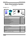
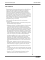
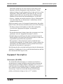
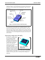
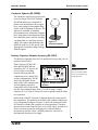
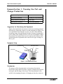
Instruction Manual Manual No. 012-07227D Basic Electrostatics System Model No. ES-9080A Basic Electrostatics System Model No. ES-9080A Table of Contents Equipment List........................................................... 3 Introduction .......................................................... 4-5 Equipment Description .............................................. 5-11 Electrometer ...................................................................................................................................5 Electrostatics Voltage Source ........................................................................................................6 Variable Capacitor .........................................................................................................................7 Charge Producers and Proof Plane............................................................................................. 7-8 Proof Plane................................................................................................................................. 8-9 Faraday Ice Pail............................................................................................................................10 Conductive Spheres......................................................................................................................11 Resistor-Capacitor Network Accessory .......................................................................................11 Electrometer Operation and Setup Requirements................12-13 Suggested Demonstrations ........................................14-34 Demonstration 1: Faraday Ice Pail and Charge Production ................................................... 14-17 Demonstration 2: Charge Distribution................................................................................... 18-20 Demonstration 3: Capacitance and Dielectrics ...................................................................... 21-29 Demonstration 4: Charging and Discharging Capacitors ...................................................... 30-34 Technical Support ...................................................... 35 Copyright and Warranty Information................................. 36 2 ® Model No. ES-9080 Basic Electrostatics System Basic Electrostatics System Model No. ES-9080 Equipment List 2 4 5 6 6 1 3 Included Equipment Replacement Model Number* 1. Basic Electrometer (1)** ES-9078 2. Electrostatics Voltage Source (1)** ES-9077 3. Basic Variable Capacitor (1)** ES-9079 4. Charge Producers (2) and proof plane (1) ES-9075B 5. Faraday Ice Pail and Shield (1) ES-9042A 6. Conductive Spheres (2) ES-9059B *Use Replacement Model Numbers to expedite replacement orders. ** Some cables not shown Additional Equipment Required Any PASCO data acquisition device (ScienceWorkshop® 500, 750 SCSI or 750 USB interface) Resistor-Capacitor Network A computer DataStudio® or ScienceWorkshop® software CI-6400 or CI-6450 or CI-7599 ES-9053A NA CI-6870C NA = not available for sale from PASCO ® 3 Basic Electrostatics System Model No. ES-9080 Introduction Demonstrations of electrostatic phenomenon have traditionally been limited to the simplest experiments, using the most elementary equipment, because of problems with technique and apparatus. Moreover, the traditional demonstrations usually gave qualitative rather than quantitative results. PASCO has attempted to remedy this by designing the complete ES-9079 Basic Electrostatics system. This guide will give the instructor enough of a step-by-step explanation to master demonstration techniques. The range of demonstrations in this guide more than covers the material usually presented in an undergraduate unit on electrostatics. Keep in mind the following principles for your electrostatic demonstrations: • Read the “Equipment Description” of this manual, which provides information about using the equipment. • Equipment orientations - Arrange the apparatus to be used so that it is sufficiently separated and neatly arranged to insure that the students can clearly see the setup. Each demonstration includes a diagram of the suggested equipment setup. A preferred setup would also use a computer with a ScienceWorkshop® interface to display the readings from the Electrometer (ES-9078) in a computer screen that all can easily see. (You can use an analog display, for example, to show the deflections of the needle, or a digits display to show the voltage.) If a computer is not available, set the demonstration electrometer upright to allow the meter to easily be seen. Always consider how the equipment arrangement may affect charge distributions. For example, a misplaced power supply can easily change the charge distribution on a nearby sphere. Finally, always stand behind the demonstration table to avoid obstructing anyone’s view. • Earth grounds - Although it is not always strictly necessary, the demonstrator should be connected to an earth ground. Stray charges on the demonstrator can cripple an experiment. Also, keep the electrometer grounded unless specific instructions are given to the contrary. • Avoid unnecessary movement - If the demonstrator walks around or waves his/her arms excessively, charge can build up in clothing and affect the results. • Humidity - The PASCO demonstration electrometer has been designed to minimize the effects of humidity. However, a 4 ® Model No. ES-9080 Basic Electrostatics System particularly humid day can cause charges to leak off any of the apparatus, radically changing the charge distribution. To help minimize leakage, keep all equipment free of dust and oil (e.g. from fingerprints). On the other hand, a particularly dry day can cause charge to easily build up in any moving object, including people. Minimize all movement when demonstrating on a very dry day. • Practice - Nothing can ruin the instructive value of a demonstration more than failure due to a demonstrator’s unfamiliarity with the equipment and procedure. Before presenting a series of electrostatic demonstrations, the student (and of course, the instructor) should be made aware of the following: • The theory and use of the Faraday Ice Pail. (This is adequately covered in the “Equipment Description” section and in Demonstration 1.) • The possible distortion of charge density due to improper use of the proof plane. (See the “Equipment Description” section.) • Residual charge may build up in the plastic insulator between the handle and disk of the proof plane and charge producers. Make sure to ground these parts before any experiment. • The capacitance of the electrometer must be considered when calculating the magnitude of a charge from the voltage reading of the electrometer. (See Demonstration 3 for the procedure necessary to determine the electrometer’s capacitance.) By following the above principles and by practicing, the demonstrator should have a high degree of success with the demonstrations and find their educational effect of great value. Equipment Description Electrometer (ES-9078) The Model ES-9078 Electrometer is a voltmeter used for direct measurements of voltage and indirect measurements of current and charge. Because of its high (“infinite”) impedance of 1014 Ω, it is especially suited for measuring charge in electrostatic experiments. It has a sensitivity nearly 1000 times that of a standard gold-leaf electroscope, a center-zero meter that directly indicates charge polarity, and measures charges as low as 10-11 coulombs. ® 5 Basic Electrostatics System Model No. ES-9080 With these features, you’ll find that your electrostatics demonstrations and labs are easier to perform and, with quantitative data, are more informative. Zero button, ground and remove excess charge output for signal interface meter display mechanical zero adjust screw (adjust with power off) Slide to select voltage range (3, 10, 30, 100) connect test lead here connect to earth ground push to turn ON/OFF Figure 1: Front Panel Controls of the Electrometer The electrometer is powered by four AA-alkaline batteries, easily replaced by opening the back casing of the electrometer. One of the front panel range-indicator LEDs will blink slowly when the batteries need to be replaced. When replacing batteries, do not touch any of the components or wires in the integrated circuit panel, since they are all static sensitive. Electrostatics Voltage Source (ES-9077) The ES-9077 is a high voltage, ground low current power supply designed exclusively for experiments in electrostatics. It has outputs at 30 volts DC for capacitor plate experiments, and 1 kV, 2 kV, and 3 kV outputs for the Faraday ice pail and conducting sphere experiments. All of the voltage Figure 2: Electrostatics outputs (except for the 30 volt Voltage Source output) have a series resistance associated with them which limit the available short-circuit output current to about 8.3 microamps. The 30 volt output is regulated, but is capable of delivering only about 1 milliamp before falling out of regulation. 6 ® Model No. ES-9080 Basic Electrostatics System Variable Capacitor (ES-9079) The PASCO experimental variable capacitor consists of two metal plates, 20 cm in diameter, which can be adjusted to various separations. The movable plate is mounted on a calibrated slide which gives the plate separation directly in centimeters. Binding posts are provided for electrical connection to each plate. Three plastic spacers are attached to the fixed plate so that when the movable plate is made to touch these spacers, the plate separation is 1 mm. Figure 3: Variable Capacitor Use a low-capacitance cable to connect the plates to the electrometer. Keep the leads of the cables separated as much as possible to minimize capacitance. It is very important that the plates of the capacitor remain parallel. It is possible that through mishandling, they will cease to be parallel, and adjustments must be made. On the back side of the fixed plate is a second, smaller plate with three set screws. By adjusting these three screws, the two plates may be kept parallel. Keep the clear acrylic plate supports clean to prevent charge leakage from the plates. Charge Producers and Proof Plane (ES-9057A) The Charge Producers and the Proof Plane are electrostatic components for use with the PASCO Electrostatic System. The charge producers are used to generate charges by contact. The proof plane is used to measure charge density on a charged surface. white surface conductive disks blue surface non-conductive neck Figure 4: Charge Producers The charge producers consist of two wands, one with blue and one with white material attached to a conductive disk, as shown in Figure 4. If the blue and white surfaces are briskly rubbed together, the white surface acquires a positive charge, and the blue surface acquires a negative charge. ® 7 Basic Electrostatics System Model No. ES-9080 Here are some guidelines in the proper use and care of the charge producers that are important to remember: • If a zero charge is desirable, discharge the charge producers by touching the conductive disk to ground. To be sure the disk is fully discharged, gently breathe on the non-conductive neck. The moisture from your breath will help remove any stray charge. • Avoid touching the neck during normal use. The oils from your hands will provide a path for charges to leak off. If you experience a lot of leakage, wash the white insulator shafts with soap and water, rinsing generously; the leakage should disappear. Occasionally clean the disk surfaces with alcohol. • When you first use the charge producers, or just after cleaning, they may not produce charges readily. Rub the white surface vigorously on the conductive proof plane disk. • The charge producers are designed to be used with the ES-9078 Electrometer. They do not produce sufficient charge for use with a standard electroscope. The Proof Plane As shown in Figure 5, the proof plane is an aluminumcovered conductive disk attached to an insulated handle. The conductive disk material is carbon-filled black polycarbonate (about 103 Ω) with an aluminum disk. The nonconductive neck is white polycarbonate (about 1014 Ω). conductive disk (black) aluminum surface handle non-conductive neck (white) Figure 5: Proof Plane The proof plane is used to sample the charge density on charged conductive surfaces. A Faraday Ice Pail can then be used to measure the charge density on the proof plane. 8 NOTE: The proof planes can be used to test for charge polarity on conductors of any shape. However, for accurate readings of charge density, the conductor surface sampled has to be considerably larger than the disk of the proof plane and have a relatively large radius of curvature at the point of contact. ® Model No. ES-9080 Basic Electrostatics System By touching the proof plane to a surface, the proof plane will acquire the same charge distribution as the section of the surface it touched (See Figure 6). By measuring the charge on the proof plane, the charge density on that part of the surface can be determined. The greater the charge on the proof plane, the greater the charge density on the surface where the proof plane made contact. charge in proof plane equals charge in sampled area + + + + + + + + + + + + + + + + + + + + + + + + area sampled Figure 6: Conductive Sphere When a proof plane is touched to a conductive surface, the proof plane becomes part of the conductive surface. If the effect on the shape of the surface is significant, the sampling of the charge density will not be accurate. Therefore, always touch the proof plane to the conductor in such a way as to minimize the distortion of the shape of the surface. Figure 7 shows the recommended method for using the proof plane to sample charge on a conductive sphere. charged spheres Surface of the proof plane IS NOT tangent to the surface of the conductor. + + + + + + + + + + + + + + + + + + Surface of the proof plane IS tangent to the surface of the conductor. + + + Figure 7: Proper use of a proof plane to sample charge ® 9 Basic Electrostatics System Model No. ES-9080 Faraday Ice Pail (ES-9042A) The PASCO Faraday Ice Pail is shown in Figure 8. Originally designed by Michael Faraday, it works on the principle that any charge placed inside a conducting surface will induce an equal charge on the outside of the surface. It is an excellent product for sampling charges and charge distributions. The PASCO version illustrated above consists of two wire mesh cylinders, one inside the other, mounted on a molded plastic bottom. shield pail insulators Figure 8: Faraday Ice Pail The outer cylinder is called black lead the shield. It provides complete visibility to the red lead inside of the pail and, when grounded, helps eliminate stray charges and AC fields. The inner cylinder is the actual pail. The pail is mounted on insulated rods; the pail is 10 cm in Figure 9: Charge Induction diameter and 15 cm high. When a charged object is placed inside the pail, but without touching it, a charge of the same magnitude is induced on the outside of the pail. (See Figure 9). An electrometer connected between the pail and the shield will detect a potential difference. The greater the charge, the greater the potential difference. So even though the electrometer will give readings of voltage, it is possible to use those values as relative charge measurements. To prevent stray charges from producing erroneous results, it is extremely important that the Faraday Ice Pail be momentarily grounded prior to starting any experiment. The demonstrator must also be continually grounded while performing an experiment. The Charge Producers are used as charged objects to lower into the ice pail. The Proof Planes are used to sample surface charge densities. 10 ® Model No. ES-9080 Basic Electrostatics System Conductive Spheres (ES-9059B) The conductive spheres are used to store electrical charge. The PASCO Model ES-9059B spheres are composed of plastic resin mold plated with a copper base, outer plating of non-sulphur brite nickel, with final plating of chrome. The spheres are mounted on insulting polycarbonate rods, attached to a support base. Each sphere has a thumb-nut on the lower half that can be used for attaching a ground cable or a lead from a power supply. The sphere and insulating rods should be kept free of dirt, grease, and fingerprints to minimize charge leakage from the sphere. Figure 10: Conductive Sphere Resistor-Capacitor Network Accessory (ES-9053) The Resistor-Capacitor Network is an optional accessory that you can purchase from PASCO. -6 .22 X 10 F 8 .50 X 10 W EXT INPUT 8 1.0 X 10 W 8 2.0 X 10 W Three resistors (50 MΩ, 100 MΩ, and 200 MΩ) and two capacitors (0.47 µF and .94 µF) are wired into a switching network which permits the components to be connected in various configurations. The RC Network is designed for the Figure 11: Resistor-Capacitor study of RC time constants and Network for investigating capacitors connected in series and parallel (the RC time constants range from 25 to 200 seconds). A third capacitor (0.22 µF) can be selected in series or parallel with the other two capacitors. IN OPEN -6 .47 X 10 F GND -6 .94 X 10 F OUT ES-9053A RESISTOR - CAPACITOR NETWORK COMPONENTS: ±5% MAX. 50 VOLTS IMPORTANT: Never place more than 50 VDC across any component in the RC Network. GND On the front of the RC Network, a diagram shows the connection of the components. The positions of the three slide switches indicate the exact components being used. Figure 11 shows the front panel of the RC Network with the slide switches in various positions. The threeposition slide switch on the left has a very useful “Open” position. It is often convenient to stop the charging process when making a measurement, and the “Open” position permits the circuit to be disconnected from the power supply. ® 11 Basic Electrostatics System Model No. ES-9080 Five binding posts allow the voltage source and/or the electrometer to be connected to components. Electrometer Operation and Setup Requirements The controls on the front panel of the electrometer are explained in Figure 1. Whether you are using the electrometer to measure voltage, current or charge, the setup procedure should be followed each time you turn on the electrometer. Warning: To avoid electrical shock and/or injury, observe the following safety precautions: 1. Never use the electrometer for measuring potentials more than 100 volts. 2. Never connect the electrometer to an electrostatic generator, such as a Van de Graff generator of a Wimshurst machine. 3. Never touch the input leads until you have grounded yourself to an earth ground. A person walking across a rug on a cool, dry day can easily acquire a potential of several thousand volts. Setup 1. Before turning on the electrometer, check to ensure that the meter reads zero. If not turn the Mechanical Zero Adjust screw, located just below the electrometer face, until it does. 2. Connect the test lead to the input connector of the electrometer. 3. Connect the ground post of the electrometer to an earth ground. 4. Push the power button ON. One of the range switch LEDs will blink twice in quick succession. 5. To zero the meter, press the ZERO button. You’re now ready to use the electrometer to measure charge, current or voltage. 6. Set the range switch to the desired voltage range. The range setting refers to the voltage input required to produce a full-scale meter 12 ® Model No. ES-9080 Basic Electrostatics System deflection (e.g., a setting of 30 means that a full-scale meter deflection indicates a voltage of 30 volts). Important Points for General Operation: 1. Between measurements, always press the Zero button to discharge all current from the electrometer. 2. Shorting the test leads together is insufficient. There may still be stray charges within the electrometer circuitry. 3. For good results, it is essential that the electrometer be connected to an earth ground (a water pipe or the ground wire from a 120 VAC socket). Only an earth ground provides a sufficient drain for excess charges that may build up during an experiment. It is also helpful if the experimenter is grounded. Just touch one hand to a good earth ground just before, or during measurements. More information on taking accurate measurements is provided in the demonstrations on pages 14-34. ® 13 Basic Electrostatics System Model No. ES-9080 Demonstration 1: Faraday Ice Pail and Charge Production Equipment Required: Electrometer (ES-9078) Faraday Ice Pail (ES-9042A) Charge Producers (ES-9057B) Test Leads Earth ground connection Proof plane (optional) Suggestions for Introducing the Experiment Start by showing that the electrometer is directly measuring potential difference by connecting a battery to it and measuring its voltage. You can explain that when using the ice pail, you will be only indirectly measuring charge, knowing that the amount of charge is proportional to the voltage. The readings will be in volts, not in coulombs. Change the polarity of the leads to show how the meter needle deflects in the opposite direction. Explain how this can tell us the type of charge in the ice pail. Equipment Setup grounded shield black lead (to shield) shield electrometer red lead (to pail) pail earth ground Figure 1.1: Demonstration Setup Introduction The purpose of this demonstration is to investigate the relation between the charge induced on the ice pail by a charged object placed in the pail, and the charge of the object. This demonstration is also useful for investigating the nature of charging an object by contact as 14 ® Basic Electrostatics System Model No. ES-9080 compared to charging it by induction, and to demonstrate the conservation of charge. Before beginning any experiment using the ice pail, the pail must be momentarily grounded. When the ice pail is connected to the electrometer, and the electrometer is connected to an earth-ground, simply press the ZERO button whenever you need to discharge both the pail and the electrometer. While conducting an experiment, it is convenient to keep yourself grounded, by continuously resting one hand on the upper edge of the shield, or by direct contact with the earth-ground connector. WARNING: Make sure the electrometer is connected to an earth ground, or the pail will not be properly grounded. Performing tests or experiments with an ungrounded pail could cause possible electrical shock or injury. touch both the pail and the shield at the same time shield lift finger from pail, then from shield pail shield pail Figure 1.2: Grounding the ice pail Procedure 1A: Charging by Induction vs. Charging by Contact 1. Connect the electrometer to the Faraday Ice Pail as shown in Figure 1.1. Make sure to ground the electrometer and the ice pail. The electrometer should read zero when grounded, indicating there is no charge in the ice pail. Press the Zero button to completely remove all charge from the electrometer and the ice pail. 2. Always start with the voltage range in the higher setting (100 V) and adjust down if needed. Analog meters are typically most accurate in the range of 1/3 to 2/3 of full scale. 3. The charge producers will be used as charged objects. Here is a general procedure to follow when charging the producers: 15 ® Basic Electrostatics System Model No. ES-9080 • Always remove any stray charge on the necks and handles of the charge producers by touching the necks and handles to the grounded shield. You must also be grounded while doing this. It also helps if you breathe on the neck of the charge producer, so that the moisture in your breath removes any residual charge on the neck. • Rub the white and blue surfaces together to separate charges. • Keep in your hand only the producer you are going to use. Put the other charge producer away, far from contact with any of the ice pail surfaces. • Before inserting the charged disk in the ice pail, make sure you’re touching the grounded shield. 4. Carefully insert the charged object into the ice pail, all the way to the lower half of the pail, but without letting it touch the pail. Note the electrometer reading. 5. Remove the object and again note the electrometer reading. If the handle never touched the pail, the reading must be zero. Question: Why was there a potential difference between the pail and the shield only while the charged object was inside? 6. Push the Zero button to remove any residual charge. Now insert the object again, but let it touch the ice pail. Make sure your students know and see that you are touching the ice pail with the charged disk this time. 7. Remove the object and note the electrometer reading. Questions: Why is there now a permanent potential difference between the ice pail and the shield? Where did the charge on the ice pail come from? 8. To show that the charge gained by the ice pail was lost by the disk, ground the ice pail to remove all charge. Press the ZERO button to remove residual charges from the electrometer. Insert the wand again into the ice pail. Does any charge remain on it? Procedure 1B: Conservation of Charge 1. Starting with initially uncharged charge producers, rub the blue and white materials together. Follow the general procedure for charging listed in part 1A, except that in this case you must keep both producers 16 ® Model No. ES-9080 Basic Electrostatics System from touching anything else after charging. (Keep them in your hands, without letting them touch each other or the ice pail.) 2. Use the Faraday Ice Pail to measure the magnitude and polarity of each of the charged wands by inserting them one at a time into the ice pail and noting the reading on the electrometer. Questions: What is the relation between the magnitude of the charges? What is the relation between the polarity of the charges? Was charge conserved in the demonstration? 3. Completely remove all charge from the charge producers by grounding them. Do not forget to also remove any stray charge from the necks and handles. 4. Insert both charge producers into the ice pail and rub them together inside the pail. Note the electrometer reading. Do not let the charge producers touch the pail. 5. Remove one charge producer and note the electrometer reading. Replace the charge producer and remove the other. Note the electrometer readings. Using the magnitude and polarity of the measurements, comment on conservation of charge. Extra Things to Try 1. Try repeating Procedure 1A with the opposite charged wand. 2. Try rubbing the white charge producer with a proof plane, then measure the magnitude and polarity of the charges produced. 3. Try rubbing the blue material with a proof plane. Measure the magnitude and polarity of the charges produced. 4. Construct a list of materials such that if a material lower in the list is rubbed with a material higher in the list, the higher material is always positive. ® 17 Basic Electrostatics System Model No. ES-9080 Demonstration 2: Charge Distribution Equipment Required: Electrometer (ES-9078) Faraday Ice Pail (ES-9042A) Electrostatic Voltage Source (ES-9077) Proof Planes Conductive Spheres, 13 cm (ES-9059B) (2) Test leads Earth ground connection (patch cord) Equipment Setup charged sphere pail electrometer DC voltage source* sampling sphere ground VDC source to earth or to shield power cord earth ground electrometer, shield and VDC source share common ground Figure 2.1 Demonstration Setup *An earth ground for the system is obtained through the DC voltage source wall-mount power. Introduction The purpose of this demonstration is to investigate the way charge is distributed over a surface by measuring variations of charge density. A charged surface will be sampled with a proof plane. The proof plane will then be inserted in the Faraday Ice Pail to measure the charge. By sampling different sections of the surface, the relative charge density can be observed. For example, you may find that the amount of charge on two equal sized regions on the surface of a conductor may differ in magnitude or even in sign. This occurs for non-uniform charge distribution. Alternately, you may observe that everywhere on the surface the charge has the same magnitude and sign. This occurs for uniform charge distribution. An important aspect of measuring charge distributions is charge conservation. The proof plane removes some charge from the surface it samples. If the proof plane is grounded after each measurement, the surface will be depleted of charge with consecutive measurements. However, by not grounding the proof plane (and by not letting it touch 18 ® Model No. ES-9080 Basic Electrostatics System the ice pail), the charge on the surface is not depleted. That charge which the proof plane removed for one measurement is always returned to the surface when the next sampling is made. NOTE: When the disk of the proof plane touches the surface being sampled, it essentially becomes part of the surface. To minimize distortion of the surface shape when sampling, hold the proof plane flat against the surface, as indicated in the accessory instructions. Please refer to the accessory instructions for details on how to use the proof planes. Procedure: 1. Before starting, make sure the Faraday Ice Pail is properly grounded, with the shield connected to earth ground. The electrometer, connected to the pail, must also be grounded. Follow the setup in Figure 2.1, with the black lead connected over the edge of the shield and the red lead connected over the edge of the ice pail. 2. Place the two aluminum spheres at least 50 cm apart. Connect one of the spheres to the Electrostatic Voltage Source (ES-9077), providing 2000 VDC. The voltage source is to be grounded to the same earth ground as the shield and the electrometer. The connected sphere will be used as a charging body. 3. Momentarily ground the other sphere to remove any residual charge from it. 4. Start the demonstration by sampling and recording the charge at several different points on the sampling sphere. (The sphere that was grounded in step 2.) Choose points on all sides to represent an overall sample of the surface. 5. Now bring the 2000 VDC sphere close to the grounded sphere, until their surfaces are about 1 cm apart. Turn the voltage source ON, then sample and record the charge at the same points sampled before. 6. Momentarily ground the sampling sphere again, by touching one hand to the grounded ice pail shield and the other hand to the sphere. (Make sure the ice pail is grounded before doing this.) Again, sample and record the charge at the same points sampled before. 7. Remove the 2000 VDC sphere until it is at least 50 cm away from the sampling sphere. Again, sample and record the charge at the same points sampled before. ® 19 Basic Electrostatics System Model No. ES-9080 Analysis 1. What produced the charge distributions at each step of the experiment? 2. Why did any charge remain on the second sphere even after it was grounded? Extra Things to Try 1. To show that the charge on a conductor always resides on the outside surface, bend a flexible sheet of metal into a cylinder. Charge the cylinder and measure the charge density in the inner and outer surfaces. Notice that charge is always on the outside. 2. To show how the surface shape affects charge density, try touching two charged proof planes together so that they are symmetrical around their point of contact. Measure the charge on each. Next touch them in an asymmetrical manner and measure the charge in each. Does one have more charge than the other? Which one? (Be sure to eliminate stray charges from necks and handles, to prevent erroneous readings.) Symmetric Planes Asymmetric Planes Figure 2.2: Test of Different Sampling Configurations 20 ® Model No. ES-9080 Basic Electrostatics System Demonstration 3: Capacitance and Dielectrics Equipment Required: Electrometer (ES-9078) Faraday Ice Pail (ES-9042A)l Charge Producers (ES-9057B) Proof Planes (ES-9057B) Electrostatic Voltage Source (ES-9077) Test leads 13 cm Conductive Spheres (2) (ES-9059B) Variable Capacitor (Parallel Plates) (ES-9079) Capacitor (about 30 pF) (ES-9043) Sheet of dielectric material (See Table 3.1 for options) Introduction The purpose of this series of demonstrations is to investigate the relationship between charge, voltage and capacitance for a parallel plate capacitor. Each one of the variables will be held constant in turn, varying one of the others while measuring the third. The capacitance of εA a parallel plate capacitor is given by C = -----d , where ε is the dielectric coefficient, A is the plate area, and d is the plate separation. Various materials can be inserted between the plates to measure the dielectric coefficient of the materials. NOTE: At this point, the students should understand the theory of capacitors connected in parallel. If not, go to Procedure D of this demonstration. For all experiments, the electrometer can be thought of as an infinite impedance voltmeter in parallel with a capacitor, as shown in Figure 3.1. The capacitor CE represents the internal capacitance of the electrometer, plus the capacitance of the leads. Whenever you want quantitative measurements of charge, voltage or capacitance, you need to consider the effect of the internal capacitance of the electrometer, unless you are certain that the capacitor you are using has a high enough capacitance to disregard CE. The capacitors in the PASCO RC Network (ES-9053), for example, are high enough that ® 21 Basic Electrostatics System Model No. ES-9080 CE need not be considered. This is not true, however, when using the Basic Variable Capacitor (ES-9079). CE Cext Capacitance of object connects to the Electrometer Voltmeter Internal capacitance = 25 pF, without cable Figure 3.1: Ideal Schematic of the Electrometer Procedure 3A: Measuring the Electrometer’s Capacitance Use this procedure to measure a precise value of the capacitance provided by the electrometer and all cables connected to it. If you are interested in qualitative, rather than quantitative experiments, this procedure is not necessary. When a capacitor of known capacitance C is charged by a known voltage V, the charge in it is given by Q=CV. If the known charged capacitor is connected across the leads of the electrometer, it is connected in parallel with the internal capacitance of the electrometer, CE. The total capacitance becomes C + CE. The known capacitor will discharge across the electrometer and a voltage, VE, will be read. Since the total charge in the system is still just the charge of the known capacitor, we know that CV=(C + CE)VE. 1. Obtain a low leakage (polypropylene, or air dielectric) capacitor of known value, C, around 30 pF. 2. Charge the capacitor with a known voltage V, not higher than 100 V (the limit of the electrometer). 3. Remove the charged capacitor from the power supply used to charge it, being careful not to ground it in any way, to avoid removing the charge. 4. Connect the charged capacitor across the electrometer input leads. Note the voltage VE indicated by the electrometer. 5. Calculate the internal capacitance of the electrometer. 22 ® Model No. ES-9080 Basic Electrostatics System ( V – VE ) CE = ---------------------- ⋅ C V Procedure 3B: Measuring C, V and Q for a Parallel Plate Capacitor The purpose of the experiments listed in this part is to qualitatively study the relationship between C, V, and Q for the parallel plate capacitor. Values read by the electrometer are to be used as relative, comparative measurements. The electrometer can be connected to a computer and used with a ScienceWorkshop interface to obtain a graphical display of information. 3B.1: V Measured, Q Variable, C Constant 1. Figure 3.2 below shows the equipment set up. The Parallel Plate capacitor is connected to the electrometer. The electrometer is grounded to earth. One of the spheres is connected to the voltage source, set at 2000 VDC. Take care to place the capacitor sufficiently far away from the sphere and the voltage source, to prevent it from being charged by induction. basic variable capacitor electrometer sphere power 2000 VDC d proof plane to earth ground Figure 3.2: Demonstration Setup 2. Press the ZERO button to remove any residual charge from the electrometer and the plates of the capacitor. 3. Set the plate separation to about 2 mm. Use a proof plane to transfer charge from the charged sphere to the capacitor plates. The charge is transferred merely by touching the proof plane to the sphere and then to one capacitor plate. If you always touch the sphere and the capacitor plate at the same place, equal amounts of charge will be transferred each time. Question: Why is it sufficient to touch only one plate of the capacitor? ® 23 Basic Electrostatics System Model No. ES-9080 4. Observe how the potential difference reading from the electrometer varies as more charge is put in the capacitor. 5. Double the plate separation and repeat the experience. What happens to the potential now? Compare the values to the previous case. black lead d red lead 2000 V Figure 3.3: Demonstration Setup 3B.2: Q Measured, C Variable, V Constant 1. Figure 3.3 above shows the equipment set up. The Parallel Plate capacitor has an initial plate separation of 6 cm and is connected to the voltage source, set at 2000 VDC. The Faraday Ice Pail is connected to the electrometer, and the electrometer is grounded to earth. 2. Momentarily ground a proof plane and then use it to examine the charge density of the capacitor, using the ice pail to measure the charge. Investigate the charge density at various points on the plates — both on the inner and the outer surfaces. How does the charge density vary over the plate? 3. Choose a point near the center of one capacitor plate and measure charge density in this area at different plate separations. (Keep in mind whether you are increasing or decreasing the capacitance by moving the plates.) How does the charge vary with capacitance? 3B.3 Q Measured, V Variable, C Constant 1. Figure 3.3 shows the equipment set up, which is identical to the setup for B2. The Parallel Plate capacitor has an initial plate separation of 6 cm and is connected to the voltage source, set initially at 3000 VDC. The Faraday Ice Pail is connected to the electrometer and the electrometer is grounded to earth. 2. Keep the plate separation constant and change the potential across the plates by changing the setting of the voltage source. You have 24 ® Model No. ES-9080 Basic Electrostatics System to move the connecting cable from the 3000 V to the 2000 V slot. Examine the charge density near the center of one capacitor plate. How does the charge vary with the voltage? Repeat with 1000 VDC. 3B.4: V Measured, C Variable, Q Constant 1. Figure 3.4 shows the equipment set up. The Parallel Plate capacitor is connected to the electrometer and the electrometer is Figure 3.4: Demonstration Setup grounded to earth. The voltage source will be used to only momentarily charge the capacitor. 2. With the plate separation at 2 mm, charge the plates by momentarily connecting them across the voltage source, set at 30 V. Adjust the scale sensitivity of the electrometer so that the initially charged plates represent a meter reading of about 1/5 scale. 3. Increase the plate separation and note the electrometer’s readings at various separations. How does the potential vary with capacitance? NOTE: An alternative method is to charge one of the spheres and then transfer some charge to the capacitor. The charge, however, will not be as high. Procedure 3C: Dielectric Coefficients The dielectric coefficient κ is the dimensionless factor by which the capacitance increases (relative to the value of capacitance before the dielectric) when a dielectric is inserted between the plates. It is a fundamental property of the dielectric material and is independent of the size or shape of the capacitor. Table 3.1 on page 28 lists the dielectric coefficients of some common materials. The ideal procedure to measure κ would be to simply slip a piece of dielectric material between a set of charged capacitor plates and then note the changes in potential. However, sliding a dielectric between the plates of the capacitor when they are too close together can generate a significant static charge that will alter the measurements. Hence, it is best to proceed as follows: ® 25 Basic Electrostatics System Model No. ES-9080 NOTE: Depending on the model of parallel plate capacitor you have, there may be only one plate that is movable. If your model allows both plates to be moved, choose one to keep fixed and the other to be the movable one. 1. Connect the electrometer across the plates of the capacitor and set the separation between the plates to about 3 mm. 2. Raise the side of the set up nearest the movable plate by setting a block about 3 cm high below it, as shown in Figure 3.5. 3. Use the voltage source to momentarily touch the plates and charge them to about 4/5 full scale. Record the voltage reading of the electrometer, Vi. movable plate fixed plate block Figure 3.5: Experimental Setup 4. Carefully increase the separation of the plates until it is enough to insert the dielectric without forcing it. It should be enough so that you can simply lean the dielectric sheet against the stationary plate. Make sure the dielectric you are using is free of residual charge before inserting it. 5. After inserting the dielectric, return the plates to the original 3 mm separation and record the new electrometer reading, Vf. 6. Pull the plates apart again, and lift and carefully remove the dielectric sheet. 7. Return the plates to the original 3 mm separation and check that the electrometer reading agrees with the original Vi reading. 26 ® Model No. ES-9080 Basic Electrostatics System Analysis: The calculations needed to determine the dielectric constant are long, but straight forward: CE , qE before CE , qE CP qP CP qP VO VO after Figure 3.6: Circuit diagrams with and without the dielectric Before inserting the dielectric... Let q p be the charge on the capacitor plates, and C p be the capacitance of the plates, without the dielectric. Let q E be the charge on CE, the internal capacitance of the electrometer. Let Vi be the initial reading of the electrometer. The total charge in this initial system is given by qP + qE = ( CP + CE ) Vi After inserting the dielectric… Let q ′ p be the new charge on the capacitor plates; the capacitance is now C ′ p . Let q ′E be the new charge on CE , the internal capacitance of the electrometer. Since there is no dielectric in CE , its value is still the same. Let Vi be the new reading of the electrometer. The total charge in the system after inserting the dielectric is given by q ′ p + q ′ E = ( C ′ + C )V p E f Now, the total amount of charge in the system was never changed, so qp + qE = q ′p + q ′E and ( C p + C E ) V i = ( C ′ p + C ′ E ) V f ® 27 Basic Electrostatics System Model No. ES-9080 After some algebra and rearranging, you find that CE ( Vi –Vf ) + Cp V C ′p ------- = --------------------------------------------i Cp Cp Vf where the ratio ( C ′p ⁄ Cp ) is the dielectric coefficient κ : ε Ad C′ κ = ----------= -------p Cp εO Ad Table 3.1: Some Dielectric Coefficients κ Material Vacuum 1 Air 1.00059 Polystyrene 2.6 Paper 3.7 Pyrex 4.7 Mica 5.4 Porcelain 6.5 Procedure 3D: Capacitors in Series and in Parallel The purpose of this demonstration is to examine the effect of placing capacitors in series and in parallel. You will need two capacitors of known value (between 200 - 400 µF, to ignore the internal capacitance of the electrometer), a DC voltage source, the electrometer, some cables, and a double throw switch. B A C1 V 3.7a Series A C2 C1 V B C2 3.7b Parallel Figure 3.7: Circuit Diagrams 28 ® Model No. ES-9080 Basic Electrostatics System 3D.1: Capacitors in Series Make sure all capacitors are uncharged before connecting them. (Use a short wire to momentarily short each one.) 1. Set up the series circuit, as shown in Figure 3.7a. 2. Plug in to the 30 VDC output on the Voltage Source. Close switch A to charge capacitor C1. 3. Using the known value of C1, calculate the initial amount of charge on C1. Let’s call it Qo. (Remember Q=CV.) 4. Throw the switch to position B. C1 and C2 are now in series. 5. Use the electrometer to measure the voltage drop across each of the capacitors (V1 and V2). 6. Using the known values of capacitance, determine the amount of charge in each of them. (Q1 and Q2). 7. Questions: Can you find a relation between V1, V2 and the voltage of the source? How does Q1 and Q2 relate to the original charge on C1? 3D.2: Capacitors in Parallel 1. Make sure all capacitors are uncharged before connecting them to the circuit. 2. Set up the parallel circuit, as shown in Figure 3.7b. 3. Set the voltage source to 30 VDC. Close the switch to charge the capacitors. 4. Use the electrometer to measure the potential difference across each of the capacitors. How does it compare to the voltage of the source? 5. Use the known value of the capacitances to determine the charge in each capacitor. How are the charges related? Analysis: 1. Compare series and parallel capacitors in terms of charges, voltages and capacitance. ® 29 Basic Electrostatics System Model No. ES-9080 Demonstration 4: Charging and Discharging Capacitors Equipment Required: Electrometer (ES-9078) Faraday Ice Pail (ES-9042A) Power Amplifier (CI-6552A) Test leads Capacitors, 200-400uF Resistors, (10-90k Ω ; 10-1000 Ω ) Computer with ScienceWorkshop® interface DataStudio® or ScienceWorkshop software Introduction The purpose of this demonstration is to investigate how the voltages across a capacitor and a resistor vary as the capacitor charges and discharges, and to find the capacitive time constant. When a capacitor is connected to a DC power supply, charge builds up in the capacitor and the potential difference across the capacitor increases until it equals the voltage of the source. Both the charging and the discharging of a capacitor are characterized by a quantity called the time constant , which is the product of the capacitance, C and the resistance R. That is, τ = RC . Use capacitor values in the recommended range, so that the internal capacitance of the electrometer needs not be considered. You can adjust the resistance value for a convenient RC constant. There are two variations of the same activity presented here. The first uses a direct DC voltage source and results are obtained in a voltage vs. time graph. Use higher resistances (10-90 k Ω for this method. The second uses a signal generator with a square wave to charge and discharge the capacitor. Use lower resistances (100-1000 Ω for this method. Equipment Setup The signal output cable of the electrometer allows it to be connected to a ScienceWorkshop interface as an analog sensor. 1. Open the software program and select the electrometer from the list of sensors. 30 ® Model No. ES-9080 Basic Electrostatics System 2. Set up the circuit shown in Figure 4.1, where the resistor and the capacitor are connected in series to the voltage source, set at 30 VDC. The electrometer output goes to one of the analog channels of ScienceWorkshop. Use a single-pole double-throw switch. signal output red lead double-throw switch electrometer interface signal black lead Figure 4.1: Experimental Setup and Circuit 3. Set up your experiment display in the computer to plot voltage vs. time. (Refer to the steps listed above for correcting the electrometer readings.) 4. With the switch open, press start to begin collecting data. Throw the switch to position A to begin charging the capacitor. Observe the behavior of the voltage on the screen. 5. When the charge in the capacitor has reached the value of the source (30 VDC), flip the switch to position B to begin discharging the capacitor. Observe the behavior of the voltage in the screen. 6. You may want to try the experiment with different values of R and notice the differences in charging time. Analysis: When a capacitor is charged through a resistor from a DC power supply, the charge on the capacitor and the voltage across the capacitor increase with time. The voltage, V, as a function of time is given by V = V0 (1 - e t/RC) where V0 is the charging voltage. After a time t = RC (one time constant), the voltage across the capacitor has increased to 63% its maximum value (V = 0.63V0 at t = RC ). ® 31 Basic Electrostatics System Model No. ES-9080 1. Calculate 63% of the voltage of the source. Locate the position in the graph where the voltage has reached this value. How long a time has passed to reach 63% of the voltage of the source? This time is RC. (Using the Smart Tool in Data Studio or the Smart Cursor Tool in ScienceWorkshop makes these measurements easy!) 2. Compare the measured time constant from the graph with the calculated from the known values of and R. Now, when a fully charged capacitor is discharged through a resistor, the voltage across (and the charge on) the capacitor decreases with time according to the equation V = V 0 e l ⁄ RC . After a time t = RC (one time constant), the voltage across the capacitor decreases to 37% its maximum value. 3. Determine how much is 37% of the total voltage and locate where in the discharging plot this value has been reached. How long a time since the start of discharging did it take to reach this value? (Use the smart cursor tools!) 4. Compare this measured RC constant with the known value. Procedure 4B: Charging/Discharging Capacitors with Signal Generator When a positive square wave signal is applied to a capacitor in an RC circuit, the capacitor periodically charges and discharges, as shown in Figure 4.2. The period of a full charge-discharge equals the period of the wave. V Vo Figure 4.2: Charging and Discharging with a Square Wave Signal Note: The procedure listed here specifies values for R, C and the frequency of the signal that work well together. If you decide to use any other R or C value, you have to adjust the frequency of the wave. Notice that the voltage has to remain constant for enough time to fully charge the capacitor before the voltage goes to zero and the capacitor is discharged. A good estimate of the time needed to fully charge a capacitor can be determined as t = RC[lnVo 32 ® Model No. ES-9080 Basic Electrostatics System - ln0.01], where Vo is the voltage of the source. Choose a signal such that the period of the wave is at least double this charging time. analog channel interface computer electrometer Figure 4.3: Experimental Setup Experimental Setup 1. Set up the circuit shown in Figure 4.3, where the resistor and the capacitor are connected in series to the signal output generator of the ScienceWorkshop interface. Use a 200µF capacitor and a resistance of 1000 Ω. Τhe electrometer is reading the voltage across the capacitor, and it is also connected to one of the analog channels of the Science Workshop interface. 2. With the DataStudio or ScienceWorkshop software, create a display of voltage vs. time for the readings of the electrometer. 3. Set the signal generator to produce a positive square wave of maximum around 4 volts and of frequency 0.45 Hz. Set the signal generator to AUTO. In this way, the signal will turn on and off as you press Start or Stop to collect data. 4. Start recording data. Observe the behavior of the voltage across the capacitor on the screen. When several cycles of chargingdischarging have completed, stop the collection of data. 5. Only one full cycle is necessary to complete all the analysis. Zoom in to a full cycle of charge-discharge. Analysis: The analysis is similar to the analysis for Procedure A. ® 33 Basic Electrostatics System Model No. ES-9080 Extra Things to Try: 1. Check what is happening to the voltage across the resistor while the capacitor charges and discharges. 34 ® Model No. ES-9080 Appendix A: Information Basic Electrostatics System Copyright and Warranty Copyright Notice The PASCO scientific 012-7227C Electrostatics Manual is copyrighted and all rights reserved. However, permission is granted to non-profit educational institutions for reproduction of any part of the 012-7227C Electrostatics Manual, providing the reproductions are used only for their laboratories and are not sold for profit. Reproduction under any other circumstances, without the written consent of PASCO scientific, is prohibited. Limited Warranty PASCO scientific warrants the product to be free from defects in materials and workmanship for a period of one year from the date of shipment to the customer. PASCO will repair or replace, at its option, any part of the product which is deemed to be defective in material or workmanship. The warranty does not cover damage to the product caused by abuse or improper use. Determination of whether a product failure is the result of a manufacturing defect or improper use by the customer shall be made solely by PASCO scientific. Responsibility for the return of equipment for warranty repair belongs to the customer. Equipment must be properly packed to prevent damage and shipped postage or freight prepaid. (Damage caused by improper packing of the equipment for return shipment will not be covered by the warranty.) Shipping costs for returning the equipment after repair will be paid by PASCO scientific. Credits: Author: Cicilia Hernandez ® 35 Basic Electrostatics System Model No. ES-9080 Appendix B: Technical Support For assistance with the Basic Electrostatics Systems equipment or any other PASCO products, contact PASCO as follows: Address: PASCO scientific 10101 Foothills Blvd. Roseville, CA 95747-7100 Phone: (916) 786-3800 36 FAX: (916) 786-3292 Web: www.pasco.com Email: [email protected] ®