1
Roland
MDX-40A
MDX-40A
Step-by-step guide
Vol.1
Patrick Thorn
1
"#$%&'()$*&#
!This guide is designed to demonstrate and help you understand the workflow of one side
cutting with MDX-40A. If you read through these notes with your own model, you will
understand the principles of operation.
!The SRP Player supplied with your machine, used with this guide is ver. 1.17. If your
SRP Player is a different version, the specification and functions described may not appear
the same.
You can download the latest software updaters and Windows drivers from our corporate
website www.rolanddg.com.
Please note, you need to have the SRP Player installed from the CD, before using an updater.
2
Contents
++++++Think how best to cut the object
!!!!!!!!!!!!!!!!!
++++++++Making a prototype with single side cutting only.
++++++++The method for two sided cutting a solid object using supports and frame.
++++++++The method for two sided cutting a solid object without supports and frame.
++++++++The method using rotary axis (4 axes).
++++++++Combined cutting
4
One side cutting
,-Before you start
++++++++++Think about material and tools
++++++++++The workflow of this guide
.-Before you start cutting
!!!!!!!!!!!!!!!!!!!!!!!!!!!!!!!!
!!!!!!!!!!!!!!!!!!!
!!!!!!!!!!!!!!!!!!!!!
6
7
9
!!!!!!!!!!!!!!!!!!!!!!!!!!!!
!!!!!!!!!!!!!!!!!!!!!!!!!!!!!
!!!!!!!!!!!!!!!
!!!!!!!!!!!!!!!!!!!!!!
!!!!!!!!!!!!!!!!!!!!!!
!!!!!!!!!!!!!!!!!!!!!!!!!!!
!!!!!!!!!!!!!!!!!!!!!!
10
11
12
12
13
15
!!!!!!!!!!!!!!!!
++++3-1+Preparation of the surface - levelling the base
!!!!!!!!!!!!!!!!
+++++++++Preparation of the base
!!!!!!!!!!!!!!!!!!!!!!!
+++++++++Installing the surface levelling tool
!!!!!!!!!!!!!!!!!!!
+++13-2+Setting the origin point of MDX-40A
!!!!!!!!!!!!!!!!!!!!!
+++++++++Setting the X- and Y- axis Origin Point
!!!!!!!!!!!!!!!!!
+++++++++Setting the Z-axis Origin Point
!!!!!!!!!!!!!!!!!!!!
+++++++++Surface levelling the base
!!!!!!!!!!!!!!!!!!!!!!
+++++++++Preparation of the workpiece for model and surface levelling
!!!!!!!
16
17
+++2-1+What you will need
2-2+Equipment Configuration/Machine, Software, Driver0
++++++1MDX-40A transportation clamps
++++++1Preparation of PC and software
++++++1SRP Player settings
+++2-3+Starting the MDX-40A and VPanel
2-Setup Tasks. Cutting the Base and workpiece
3-Creating the cutting tool path
+++1 ++++Setting of the each process
4-Cutting the model
+++++++++Start cutting
19
19
20
21
23
!!!!!!!!!!!!!!!!!!!!!!!!!
!!!!!!!!!!!!!!!!!!!!!!!
24
!!!!!!!!!!!!!!!!!!!!!!!!!!!!!!!
!!!!!!!!!!!!!!!!!!!!!!!!!!!!!
29
3
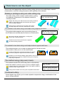
Think how to cut the object
Think of the most appropriate method of cutting, taking into account model shape, material
characteristics, machine cutting dimensions and capability of the software.
Making a prototype using one side cutting only
One side cutting, which creates a solid model by cutting
two separate components is the simplest method for
creating a model.
MDX-40A+Step-by-step guide
Step1+One side cutting
Single side cutting can make full use of the cutting machine’s
table to create larger models and eliminates the need to
remove support material.
Gluing the two components is necessary after cutting.
Accurate alignment of the two components is critical.
The method for two sided cutting a solid object using supports and frame.
This method adds supports and a surrounding frame to
the 3D data and manually flips the frame to cut both sides.
56789:;+<$=>8?@8A$=>1B(*'=
<$=>.+CD&1A*'='1)($$*#B
No need to split the original design, no alignment
issues and no gluing required.
Careful removal of the model from the supports
and hand finishing required.
The method for two sided cutting a solid object without supports and frame.
This method requires you to create a support base for the pre-cut side
of the model to allow you to cut the second side.
Finished models will be smooth and without the need to
remove any supports. Alignment should be accurate.
Preparing an accurate and stable support base for the pre-cut
side may be time-consuming. Additional fixing such as glue or
putty may be required.
The method using rotary axis (4 axis).
This method uses the ZCL-40A rotary axis to automatically
rotate the model in order for you to cut from multiple angles.
A simple method for cutting multiple sides. This makes it easier to
create accurate complex models.
Cutting area is limited to the rotary axis’ acceptable material size.
ZCL-40A+Step-by-step guide
Step,+Basics
ZCL-40A+Step-by-step guide
Step.+Cutting utilizing the area
Combined cutting
Some objects may require you to create separate components using a combination of the
above cutting methods.
4
One side cutting
With MDX-40A
and
SRP Player
5
Step 1.
Before you start
Choose your material and tools and think
about the process required to complete
the model.
6
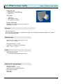
Step 1. Start up
CE*#F1G?&($1$E=1HG$=%*GI1G#'1$&&IA
In this guide, a 6mm diameter ball endmill is used for roughing and finishing cutting and Sanmodur 7K has been
chosen as the material. However, cutter sizes will be influenced by your part.
1
JE&&A=1$E=1HG$=%*GI
O
K
L
M
N
Consider the following when choosing your material:
+!How strong does it need to be?
+!How durable does it need to be to withstand operation testing?
!Once cut, will it need painting or coating?
+!Does your design require a particular material finish such as
wood grain or high gloss?
+!Is the material readily available?
+!Is the material cost appropriate to the project?
P"f there is no specific requirement, or you have less experience in
cutting, you may wish to use a modelling board such as Sanmodur.
Sanmodur 7K is what is typically used in Roland DG Japan (local
alternative modelling boards are also available).
The MDX-40A was specifically developed to work with a wide range of
synthetic and natural materials
The following list describes the key characteristics of the most popular synthetic resin
materials:
K1Sanmodur
+1+1Also known as chemical wood or modelling board. There are many variations in density, colour and
surface finish. All are lightweight and easy to cut. The cutting waste is a powdery dust. It is often used
for initial concept prototypes in order to check shape, size, etc.
L1Modelling Wax
++1This hard form of wax is supplied in varying blocks, tubes, sheets and cylinders for modelling. It is easy
to cut but can also melt with the heat generated by the cutting tool. Modelling wax is particularly
popular for investment casting products such as jewellery and dental applications.
M1ABS
++1ABS is a high-impact resistant plastic which is light and rigid, making it suitable for many moulding and
machining applications. It offers good electrical insulation, but has low resistance to certain chemicals.
It is widely used for the automotive parts, helmets and tubing applications.
N1Polyacetal resin
+++Also known as POM (polyoxymethylene), Jura Kon, and acetal resin. Used heavily in thermalplastic
applications for precision mechanical parts. It is durable, dimensionally stable and resists oil and
solvents. Commonly used to make small mechanical components such as gears in CD players, etc.
O1Acrylic
Acrylic is a hard weather resistant, transparent thermoplastic which can be cut, engraved, glued and
thermo-formed. It is widely used for signage, display cases, aquariums, screen protectors and light
clusters – basically where a UV stable transparent material is required. The material is prone to
scratching and can melt when machined.
7
Step 1. Start up
CE*#F1G?&($1$E=1HG$=%*GI1G#'1$&&IA
2
Choose the tool
The main characteristics when choosing a tool is the tip shape, blade
diameter, flute length and shaft diameter.
For Rough cutting
+++++For fast and efficient rough cutting, you should use the widest tool which will take away the majority of
the unwanted material as quickly as possible. The largest diameter tool you can use with the MDX-40A is
6mm. However, this may be too wide for the geometry of smaller models and could leave too much material
behind for a fine finishing tool to remove in holes, cavities, etc. Using a wider tool for roughing also means a
finer finishing tool will be required during the cutting process and will have to be changed manually.
Alternatively, the whole model can be cut using a smaller tool which can both rough and finish cut, but this may
take considerably longer to finish.+So you must decide whether production time is more important than
unattended operation.
For finishing
Use the tool with the diameter that can fit into the smallest space of the model.
Select the square or ball end tool depending on whether the majority of the model has flat or curved
surfaces.
Shape of the tool tip
Square (Straight)
Radius
Square end mills have cutting blades on the bottom
and sides. Although flat, the tips have a gap in the
blades in the centre, which makes them suitable for
profiling, surfacing and roughing, but not drilling. Slot
drills have continuous blades at the tip which makes
them better suited for drilling.
Also known as ‘bull nose’, the tool has a flat tip and rounded
corners, combining the elements of square and ball tools.
There are cutting blades on the tip and the sides. These tools
tend to cut faster than the ball equivalent because less
toolpaths are required. It is commonly used for roughing.
Ball
This tip has a rounded tip like a ‘ball.’
It has cutting blades on the tip and the sides.
It is very effective as a finishing tool for curved
surfaces, giving a very smooth finish.
Conical
This V-shaped tool has a flattish tip and is used extensively
for engraving and also for fine detail work such as in jewellery
wax modelling. The tip sizes vary according to the width of
cut required.
8
Step1. Setting up
The workflow of this guide
Surface
levelling the
base
Surface level
the modelling
material
Rough cutting
and Finishing
Completion
Use a 6 mm diameter straight endmill.
This will give a level base for the material, ensuring cutting
depths across the model are even.
Like the process of surface levelling the base, this cuts
the model surface so that the thickness of the workpiece
is even and appropriate for the size of model.
This tutorial uses the same 6mm straight end mill to
complete the surfacing, roughing and finishing.
Remove the completed model from the base.
9
Step 2.
Before you start cutting
This step highlights preparation required,
materials needed and the necessary
equipment configuration required to
commence the tutorial.
10
2-1 What to have ready
Step 2+Before you start cutting
Model data file
+Z0SENSOR_HOLDER.igs
+/IGS format0
This guide
++MDX-40A
++Step up guide+Step,
++One side cutting version
Double sided tape
Scraper (Long stainless steel kitchen spatulas are
particularly good for this)
[>$*&#GI
MDX-40A Starter kit
PGll the necessary equipment is included in the starter kit, comprising of modelling material, tool, parallel
pins, guide and cutting data.
Material size
Workpiece for modelling (Sanmodur) 1 piece
,.R+S+,RR+S+2RTT
Workpiece for base 1 piece
(wider than the workpiece for modelling)
.3U+V+.3U+V+2RTT
Tool
"Qmm Straight endmill
+/For surface levelling/Roughing/Finishing)
WXY-3RZ+Accessories
Spanner - 2 sizes
Hexagonal Wrench – 2 sizes
Roland Software Package/CD-ROM)
SRP Player/CD-ROM)
Collet /!Q0+
USB Cable
11
2-2 Equipment Configuration/machine, driver, software0
Step 2+Before you start cutting
MDX-40A retaining clamps for transportation
1
Ensure the retaining clamps for shipment are
removed from the MDX-40A
+See User’s manual
++Chapter 2+Installation
++++.\.+Removing and Storing the Retainers
Preparation of PC and software
1
Prepare the PC which is installed Windows XP/Vista (32bit)
2
Install Windows driver and software
+See User’s manual
++Chapter 2, Installation and Set up
++++Refer to .\3+Installing and Setting up the Software
++++++1
Installing the Windows-based Driver
+++++++1 Installing the V-Panel and Other Software
3
Install SRP Player
Refer [SRP Player install guide]
12
<$=>1]+^=_&%=1@&(1A$G%$1)($$*#B
<=$$*#B1(>1<`c1cIG@=%
1
2
3
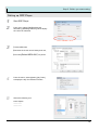
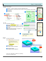
Start SRP Player
From menu, select [File][Preferences],
followed by [Modeling Machine] tab to display
the choice of machines.
K<elect MDX-40A
L`emove the check next to Rotary axis unita
MChoose [Roland MDX-40Ab1for printer
!
From the menu, select [Option], [My Tools]
to display the My Tool selection window
"
Select the following tool
6mm Square
---------------------------
13
Step 3.+Setup Tasks. Cutting the Base and workpiece
Preparation of the base
1
Prepare the base workpiece to attach to the table.
This is a sacrificial base.
Base
Ensure the base workpiece is bigger than the
model workpiece. Clean the MDX40A table to
remove any dust or swarf.
Table
.3UTT
2RTT
.3UTT
2
3
Apply just enough double sided tape
to the base Too much and you wont
get it off. Ensure the tape is flat, free
of swarf and does not wrinkle or
overlap other pieces.
Fix the base material to the table. Ensure it is
stuck firmly.
14
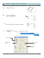
2-3 Start the MDX-40A and VPanel
1
2
#
!
Step 2+Before you start cutting
Close the front cover
Turn on the main power
switch on the MDX-40A
Turn on the sub power on the operation panel
If you use Windows XP
Select [Start] menu +d+[All program]+d+eRoland VPanel+for MDX-40Af1
d+eVPanelf+
XYZ Coordinate
Spindle rotation
button
XYZ Move
Set Origin
Point
15
Step 3.
Setup Tasks. Cutting the
Base and workpiece
Levelling the the base on the table, and
preparing the model workpiece on the
base.
16
3-1+Preparation of the surface - levelling the base
Step 3.+Setup Tasks. Cutting
the Base and workpiece
What is the base?
If the model workpiece is fixed directly to the table, the tool may damage the table when it makes the
deepest cuts. Applying a base to the table avoids cutting the table and also enables you to create
positioning frames or holes. It also means stronger adhesives such as glue can be used without damaging
the table.
What is surface levelling?
Material thickness can vary throughout a sheet. Surface levelling creates a flat surface relative to the MDX-40A.
Tool
work
work
work
Table
Table
Table
The MDX-40A machine table may not be completely level in relation to the spindle travel. Surface levelling
the base material will resolve any variation.
Exaggerated illustration
The surface levelled based
17
<$=>1hi+<=$(>1CGAFAi1J($$*#B1$E=1^GA=
G#'1D&%F>*=)=
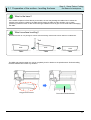
Installing the surface levelling tool
1
2
Install the collet and tool appropriate for cutting.
This tutorial requires the 6mm collet and 6mm straight end mill.
Insert the tool from below. The tool extension
length needs to exceed the cutting depth of
the workpiece. In this tutorial, the cutting
depth of the model is 28mm, so set the tool
extension from the collet to roughly 35mm
(±5mm).
P;fter surface-levelling the base, continue
on to surface-levelling the model workpiece
and making the model.
3
Tool
extension
34±4TT
Tighten the tool using the two spanners (large and
small) included in the accessory box.
Ensure the tool is held securely, but do not overtighten. Excessive force may damage the collet or
the spindle base.
Tool extension length
This is the length from the base of the collet to the tool tip.
The extension length should be enough to ensure the tool can cut the entire depth without the collet or
spindle body making contact with the workpiece.
#
g
Extension length
work
The cutting depth
Base
work
Base
18
h8]+<=$$*#B1$E=1&%*B*#1>&*#$1&_156789:;
Step 3. Setup Tasks. Cutting the
Base and workpiece
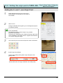
Setting the X- and Y- axis Origin Point
1
2
Draw diagonal lines from the corners of the
base material. This will give you the centre of
the material.
Start jklmnl
Change coordinate select (option [Ko in the diagram) to [User
Coordinate System]
pqser Coordinater
This allows the user to set the origin in any position.
p5achine Coordinater
These are the coordinates of the machine and the origin is set
at the initialisation point (after machine registers limit switches.
You cannot change this origin.
3
Use cursor keys to move the tool tip to the center of the base.
4
Set XY origin from VPanel.
Ksrom origin setting select [Set X origin here] then click
[Apply] button
LJheck that each XY origin coordinate now reads [0.00]
19
<$=>1hi+<=$(>1CGAFAi1J($$*#B1$E=
^GA=1G#'1D&%F>*=)=
Setting the Z-axis Origin Point
1
Place Z0 sensor on the base
2
Use cursor keys to move the tool to the position
above the sensor.
3
Set Z0 sensor from VPanel
Refer to User’s manual Chapter 5 Appendix , 5-1
‘Using the Z0 Sensor’ for details of how to use
the Z0 sensor.
KJheck [Set Z origin using sensor]
LJlick [Detect]
MChe tool slowly descends until it makes contact with
the sensor.
When the tool rises and stops, the setting operation is
complete.
NRemove the Z0 sensor from the base and use the
cursor keys to lower Z onto surface of base material to
confirm Z coordinate reads [0.00].
Z0 indicates the position where the coordinate value is set "0" as the origin of Z coordinate.
20
<$=>1hi+<=$(>1CGAFAi1J($$*#B1$E=1^GA=
G#'1D&%F>*=)=
Surface levelling the base
1
2
3
4
From Windows [Start], choose [All programs] (or
[Programs] then choose [SRP Player]
SRP Player starts
Select from menu [Option] [Surfacing] to show
surface levelling display.
Set the material to [Chemical wood (hard)].
21
<$=>1hi+<=$(>1CGAFAi1J($$*#B1$E=1^GA=
G#'1D&%F>*=)=
5
6
7
Set the tool to 6 mm Square.
For this guide, set the surface levelling area in both X
and Y to [248] to correspond with the dimensions of
the base material.
K<et the depth of surfacing relative to the
unevenness of your material. For this guide, input
[0.5mm]
LJlicking [OK] button to start cutting
If you open the front cover of the MDX-40A while
cutting, the spindle and axes will lose power. You
cannot continue cutting after an ‘emergency stop’
error.
Completed surfacing
22
<$=>1hi+<=$(>1CGAFAi1J($$*#B1$E=1^GA=
G#'1D&%F>*=)=
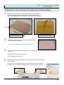
Preparation of the workpiece for model and surface levelling
1
Prepare the model workpiece using the size 120mm x 100mm x 30mm.
Draw the diagonal lines as with the base to locate the centre origin.
Apply double-sided tape to the entire area on the back of the workpiece.
Double sided
tape
,.
RT
T
,R
RT
T
2RTT
Top of model workpiece
2
Underside of model workpiece
Remove the backing from the double sided tape and fix the
model workpiece to the base.
+Ptnsure both surfaces are clean and free from dust and swarf.
3
Perform surface levelling repeating the process from Page 19 in
this guide.
Set the surfacing area to 120 x 120mm.
Set surfacing amount to 2 mm.
4
After surface levelling has completed, using Vpanel, set Z origin on the surface
of the workpiece.
You can do this by using the Z0 sensor or by lowering the Z by the surfacing
amount (2mm in this example) and selecting the option [set Z0 from here].
23
Step 4.
Creating the tool path
This step is about setting the method of
each process that is common to each
step of SRP Player.
24
Step 4.+uvwxyz{
Setting each process
1
KImport model data.
L
Click[ File ][ Open ] from the top menu bar and
open the file [Z0SENSOR_HOLDER.igs] from
where it is saved on your computer.
L1The dialog box is shown. Click [OK] and
the model will be shown in the display.
2
Check the model size and direction is correct.
K
L
K
L
3
+++1Choose the most appropriate for the 3 settings below.
K
M
K
L
L
4
M
Choose the correct material from
In this guide, choose chemical wood (hard).
25
Step 4.+Create tool path
5
Input the size of workpiece for model.
The values in brackets ( ) represent the maximum
model size in each axis. Your workpiece needs to
exceed these measurements.
6
Create cutting data (tool path)
++++++++
Click [Edit] button.
7
Set up the rough cutting values.
Click on the ‘+’ position shown below. The pallet menu will expand.
8
Select the tool
K1Select tool pallet.
L Select [6mm square]
M1Click [Apply]
K
L
K
L
M
26
Step 4.+Create tool path
9
Set the margin
KClick the ‘-’ position as below to expand the frame pallet.
L+++++++Click [Automatic ], the automatic value is relative to the tool diameter.
M Click [Apply]
N Click [Close]
L
K
K
L
M
N
What is the margin?
The margin is an additional area around the model which is cut in order to allow the model
circumference to be completed.
If no margin is set, cutting is limited to the inner model area. If too large a margin is set,
cutting time will be excessive.
10
Set up finishing
Click the ‘+’ mark as below. The expanded pallet menu is shown.
11
Select the tool
K1Select tool pallet.
L Select [6mm square]
M1Click [Apply]
K
L
K
L
M
27
Step 4.+Create tool path
12
Set the margin
K Click the ‘-’ position as below to expand the Modelling Form.
L Click [Automatic], the automatic value is relative to the tool diameter, plus a margin.
M Click [Apply]
K
N Click [Close]
L
K
L
M
13
N
L
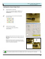
Generating cutting data
KClicking [
] generates
the toolpaths sequentially.
LThe toolpath generation progress is shown as a
percentage.
MWhen tool path generation is complete, the
display changes to [Created]
K
M
14
Check the cutting data
Click
+
+++++++++++++++++++++
K Click [Preview].
The cutting progress is simulated.
L1Click [Show model].
The completed model is displayed.
From menu, select [File] – [Save as ] ( or [Save])
and save the Whole project.
28
Step 5.
+Cutting the model
This step is explains the cutting process.
29
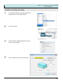
Step 5.+Cutting the model
Start cutting
1
+++++++++++++++++++++
Click [Start cutting] from [Perform Cutting tab]
2
3
As we have already surfaced the model
work piece, and we have already set the
XYZ origin, so no changes are required.
Click [Next] to continue.
Click [ Next] to start cutting
KWhile cutting, the cutting progress is displayed.
The MDX-40A now starts cutting.
L1When all the data has been machined, the
MDX-40A will stop cutting and ‘Finished’ will be
displayed.
Open front cover and clean off the cutting waste.
Start cutting
L
If you open the front cover of the MDX-40A while
cutting, the spindle and axes will lose power. You
cannot continue cutting after an ‘emergency stop’ error.
Just finished cutting
30
Step 5.+Cutting the model
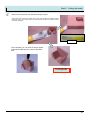
4
Remove the workpiece from the base using a scraper
PCake care when removing the model. The scraper may damage the modelling board if
excessive force is used. Gently slide the scraper between the base and model to loosen
the double sided tape.
Scraper
Once complete, you can stick the sensor holder
with double sided tape to the side of the MDX40A.
Complete
31