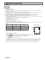
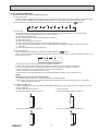
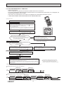
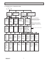
1
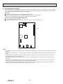
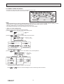
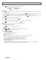
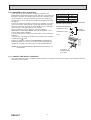
SPLIT-TYPE AIR CONDITIONERS INDOOR UNIT No. OBH697 SERVICE MANUAL Models MFZ-KJ25VE MFZ-KJ35VE MFZ-KJ50VE - A1 - A1 - A1 Outdoor unit service manual MUFZ-KJ•VE Series (OBH695) MUFZ-KJ50VEHZ Series (OBH696) CONTENTS 1. TECHNICAL CHANGES ··································· 2 2. PART NAMES AND FUNCTIONS ····················· 3 3. SPECIFICATION ················································ 4 4. NOISE CRITERIA CURVES ······························ 5 5. OUTLINES AND DIMENSIONS ························ 6 6. WIRING DIAGRAM············································ 7 7. REFRIGERANT SYSTEM DIAGRAM ··············· 8 8. SERVICE FUNCTIONS ····································· 9 9. MICROPROCESSOR CONTROL ····················11 10. TROUBLESHOOTING ····································· 18 11. DISASSEMBLY INSTRUCTIONS ···················· 33 NOTE: • This service manual describes technical data of the indoor units. • RoHS compliant products have <G> mark on the spec name plate. For servicing of RoHS compliant products, refer to the RoHS Parts List. Use the specified refrigerant only Never use any refrigerant other than that specified. Doing so may cause a burst, an explosion, or fire when the unit is being used, serviced, or disposed of. Correct refrigerant is specified in the manuals and on the spec labels provided with our products. We will not be held responsible for mechanical failure, system malfunction, unit breakdown or accidents caused by failure to follow the instructions. 1 TECHNICAL CHANGES The following models are compatible with the outdoor units with low standby power control. Connecting these models to the MUFZ-KJ·VE(HZ) series outdoor units enables the low standby power control. Low standby power control can reduce standby power about 90%. Refer to the technical guide (OBT32) about the low standby power control. With the horizontal vanes and the multi-flow vane, air blows to the expanded vertical area using only one fan. MFZ-KJ25VE - A1 MFZ-KJ35VE - A1 MFZ-KJ50VE - A1 1. New model · The model MFZ-KJ25VE- A1 or MFZ-KJ35VE- A1 is connectable with the MUFZ-KJ·VE outdoor unit or the MXZ outdoor unit. This model may be connected to the MUFZ-KJ·VE series after once connected to the MXZ series and operated, for example because of relocation. In that case, the MUFZ-KJ·VE series outdoor units will not operate without taking a step. Follow the procedure "Deleting the memorized abnormal condition" described in 10-2.1. · The model MFZ-KJ50VE- A1 is connectable with the MUFZ-KJ·VE(HZ) outdoor unit or the MXZ outdoor unit. This model may be connected to the MUFZ-KJ·VE(HZ) series after once connected to the MXZ series and operated, for example because of relocation. In that case, the MUFZ-KJ·VE(HZ) series outdoor units will not operate without taking a step. Follow the procedure "Deleting the memorized abnormal condition" described in 10-2.1. OBH697 2 2 PART NAMES AND FUNCTIONS MFZ-KJ25VE MFZ-KJ35VE MFZ-KJ50VE Air outlet Horizontal vane Vertical vane Multi-flow vane Fan guard Air cleaning filter (Anti-Allergy Enzyme Filter) Panel Front panel Air filter (Nano platinum filter) Display and operation section (When the front panel is opened) E.O SW Emergency operation switch Remote control receiving section Operation indicator lamp ACCESSORIES MFZ-KJ25VE MFZ-KJ35VE MFZ-KJ50VE Remote controller holder Fixing screw for 3.5 x 16 mm (Black) Pipe cover Band Battery (AAA) for remote controller Indoor unit mounting bracket Fixing screw for 4 x 25 mm Wood screw for the indoor unit fixation Washer of Felt tape (Used for left or left-rear piping) Wireless remote controller Air cleaning filter OBH697 3 1 2 1 2 2 1 5 4 4 1 1 2 3 SPECIFICATION Indoor model MFZ-KJ25VE Power supply Cooling Power input 1 Heating Cooling Running current 1 Heating Model Cooling Current 1 Heating Dimensions W × H × D Weight Air direction Super High High Med. Low Quiet Super High High Med. Low Quiet Super High High Med. Low Quiet Super High High Med. Low Quiet Super High High Med. Low Quiet Super High High Med. Low Quiet Fan speed regulator Remote controller model 13 16 0.14 0.17 RC0J30-KX 0.14 0.17 Electrical data W A Fan motor A Cooling m3/h Heating m3/h Cooling dB(A) Heating dB(A) Cooling rpm Heating mm kg rpm 21 38 0.20 0.34 RC0J40-PA 0.20 0.34 492 426 354 294 234 582 462 372 306 234 39 35 30 25 20 41 35 30 25 19 790 700 600 520 440 910 750 630 540 440 636 558 480 402 336 840 696 564 444 360 44 39 35 31 27 50 45 40 35 29 980 880 770 670 580 1,250 1,060 890 750 610 5 SG132 NOTE: Test conditions are based on AS/NZS3823.1.1. (Refrigerant piping length (one way): 7.5 m) 1 Measured under rated operating frequency. COOLING INDOOR OUTDOOR HEATING INDOOR OUTDOOR Dry-bulb Dry-bulb Dry-bulb Dry-bulb temperature temperature temperature temperature 27.0°C 35.0°C 20.0°C 7.0°C Wet-bulb temperature 19.0°C Wet-bulb temperature 24.0°C Wet-bulb temperature 6.0°C Specifications and rating conditions of main electric parts Model Item Fuse Horizontal vane motor (Front) Horizontal vane motor (Back) Multi-flow vane motor Terminal block Varistor OBH697 MFZ-KJ50VE 750 × 600 × 215 15 1 FLOW: 4, 2 FLOW: 4 Airflow Sound level Fan speed Special remarks MFZ-KJ35VE Single phase 230 V, 50 Hz MFZ-KJ25VE MFZ-KJ35VE MFZ-KJ50VE (F11) (MV1) (MV2) (MV3) (TB) (NR11) T3.15AL250V 12 VDC 250 Ω 12 VDC 250 Ω 12 VDC 350 Ω 3P S10K300E2K1 4 4 NOISE CRITERIA CURVES MFZ-KJ25VE MFZ-KJ35VE FAN SPEED FUNCTION Super High SPL(dB(A)) COOLING 39 HEATING 41 FAN SPEED FUNCTION LINE Super High COOLING 39 HEATING 41 LINE 80 OCTAVE BAND SOUND PRESSURE LEVEL, 0dB = 20μPa 80 OCTAVE BAND SOUND PRESSURE LEVEL, 0dB = 20μPa SPL(dB(A)) 70 60 NC-70 50 NC-60 40 NC-50 30 NC-40 20 NC-30 10 70 60 NC-70 50 NC-60 40 NC-50 30 NC-40 20 NC-30 10 NC-20 NC-20 0 NC-10 63 125 250 500 1000 2000 4000 0 8000 NC-10 63 125 250 500 1000 2000 4000 8000 BAND CENTER FREQUENCIES, Hz BAND CENTER FREQUENCIES, Hz Test conditions Cooling : Dry-bulb temperature 27 °C Wet-bulb temperature 19 °C Heating : Dry-bulb temperature 20 °C MFZ-KJ50VE MICROPHONE FAN SPEED FUNCTION Super High SPL(dB(A)) COOLING 44 HEATING 50 LINE INDOOR UNIT 1m WALL 80 OCTAVE BAND SOUND PRESSURE LEVEL, 0dB = 20μPa 1m 70 60 NC-70 50 NC-60 40 NC-50 30 NC-40 20 NC-30 10 NC-20 0 NC-10 63 125 250 500 1000 2000 4000 8000 BAND CENTER FREQUENCIES, Hz OBH697 5 5 OUTLINES AND DIMENSIONS MFZ-KJ25VE MFZ-KJ35VE MFZ-KJ50VE OBH697 Unit: mm 6 6 WIRING DIAGRAM MFZ-KJ25VE MFZ-KJ35VE MFZ-KJ50VE OBH697 7 7 REFRIGERANT SYSTEM DIAGRAM MFZ-KJ25VE MFZ-KJ35VE MFZ-KJ50VE Unit: mm Refrigerant pipe 9.52 (MFZ-KJ25/35) 12.7 (MFZ-KJ50) (with heat insulator) Indoor heat exchanger Indoor coil thermistor RT12 (main) Distributor Flared connection Indoor coil thermistor RT14, RT15 (main) RT13 (sub) Room temperature thermistor RT11 Flared connection Refrigerant pipe 6.35 (with heat insulator) Refrigerant flow in cooling Refrigerant flow in heating OBH697 8 8 SERVICE FUNCTIONS MFZ-KJ25VE MFZ-KJ35VE MFZ-KJ50VE 8-1. TIMER SHORT MODE • For service, the following set time can be shortened by bridging the timer short mode point on the electronic control P.C. board. (Refer to 10-7.) • The set time for the ON/OFF timer can be reduced to 1 second for each minute. • After the breaker is turned on, the time for starting the compressor, which normally takes 3 minutes, can be reduced to 1 minute. Restarting the compressor, which takes 3 minutes, cannot be reduced. 8-2. HOW TO SET REMOTE CONTROLLER EXCLUSIVELY FOR A PARTICULAR INDOOR UNIT A maximum of 4 indoor units with wireless remote controllers can be used in a room. To operate the indoor units individually with each remote controller, assign a number to each remote controller according to the number of the indoor unit. This setting can be set only when all the following conditions are met: • The remote controller is powered OFF. • Weekly timer is not set. • Weekly timer is not being edited. 1. How to modify the electronic control P.C. board Turn OFF the power supply before modification. To assign a number to each indoor unit , cut off “JR05” and “JR06” on the electronic control P.C. board as shown in Table 1. (Refer to 10-7.) Table 1 JR05 JR06 Unit No. 1 No modification No modification Unit No. 2 Cut off JR05 No modification Unit No. 3 No modification Cut off JR06 Unit No. 4 Cut off JR05 Cut off JR06 Indoor electronic control P.C. Board Fuse (F11) VARISTOR (NR11) JR05 JR06 R111 CN211 2. How to set the remote controller (1) Hold down button on the remote controller for 2 seconds to enter the pairing mode. (2) Press button again and assign a number to each remote controller. Each press of button advances the number in the following order: 1 → 2 → 3 → 4. (3) Press CN151 button to complete the pairing setting. After the setting, turn ON the power supply and with the remote controller headed towards the indoor unit, press the OPERATE/STOP (ON/OFF) button. If 1 or 2 beeps is heard from the indoor unit, the setting is completed correctly. The remote controller that first sends a signal to an indoor unit will be regarded as the remote controller for the indoor unit. Once they are set, the indoor unit will only receive the signal from the assigned remote controller afterwards. OBH697 9 8-3. AUTO RESTART FUNCTION When the indoor unit is controlled with the remote controller, the operation mode, the set temperature, and the fan speed are memorized by the indoor electronic control P.C. board. “AUTO RESTART FUNCTION” automatically starts operation in the same mode just before the shutoff of the main power. Operation If the main power has been cut, the operation settings remain. After the power is restored, the unit restarts automatically according to the memory. (However, it takes at least 3 minutes for the compressor to start running.) How to disable “AUTO RESTART FUNCTION” Turn off the main power for the unit. Cut the Jumper wire to JR77 on the indoor electronic control P.C. board. (Refer to 10-7.) CN201 F11 L101 JR77 C111 T111 CN211 CN111 CN104 CN105 CN123 NOTE: • The operation settings are memorized when 10 seconds have passed after the indoor unit was operated with the remote controller. • If main power is turned OFF or a power failure occurs while AUTO START/STOP timer is active, the timer setting is cancelled. • If the unit has been off with the remote controller before power failure, the auto restart function does not work as the power button of the remote controller is off. • To prevent breaker OFF due to the rush of starting current, systematize other home appliance not to turn ON at the same time. • When some air conditioners are connected to the same supply system, if they are operated before power failure, the starting current of all the compressors may flow simultaneously at restart. Therefore, the special counter measures are required to prevent the main voltage-drop or the rush of the starting current by adding to the system that allows the units to start one by one. OBH697 10 9 MICROPROCESSOR CONTROL MFZ-KJ25VE MFZ-KJ35VE MFZ-KJ50VE WIRELESS REMOTE CONTROLLER Signal transmitting section Distance of signal : About 6 m Beep(s) is (are) heard from the indoor unit when the signal is received. FAN SPEED CONTROL button OPERATION SELECT button ECONO COOL button Operation display section VANE CONTROL button i-save button AMPM AMPM TIME, TIMER set buttons FORWARD button BACKWARD button Temperature buttons WEEKLY TIMER set buttons OPERATE/STOP (ON/OFF) button RESET button CLOCK button Indication of remote controller model is on back Lid Slide the lid down to open the remote controller. Slide it down further to get to the weekly timer buttons. NOTE: Last setting will be stored after the unit is turned OFF with the remote controller. Indoor unit receive the signal of the remote controller with beeps. INDOOR UNIT DISPLAY SECTION Operation Indicator lamp The operation indicator at the right side of the indoor unit indicates the operation state. •The following indication applies regardless of shape of the indication. Indication Operation state Room temperature The unit is operating to reach the set temperature About 2°C or more away from set temperature The room temperature is approaching the set temperature About 1 to 2°C from set temperature Standby mode (only during multi system operation) Lighted Blinking Not lighted — 9-1. COOL ( ) OPERATION (1) Press OPERATE/STOP (ON/OFF) button. OPERATION INDICATOR lamp of the indoor unit turns on with a beep tone. (2) Select COOL mode with OPERATION SELECT button. or button to select the desired temperature. The setting range is 16 - 31°C. (3) Press TEMPERATURE buttons TEMP 1. Coil frost prevention The compressor operational frequency is controlled by the temperature of the indoor heat exchanger to prevent the coil from frosting. When the temperature of indoor heat exchanger becomes too low, the coil frost prevention mode works. The indoor fan operates at the set speed and the compressor stops. This mode continues until the temperature of indoor heat exchanger rises. 2. Low outside temperature operation When the outside temperature is lower, low outside temperature operation starts, and the outdoor fan slows or stops. 3. Indoor fan speed control When the thermostat turns OFF, the indoor fan operates at the setting fan speed. OBH697 11 9-2. DRY ( ) OPERATION (1) Press OPERATE/STOP (ON/OFF) button. OPERATION INDICATOR lamp of the indoor unit turns on with a beep tone. (2) Select DRY mode with OPERATION SELECT button. (3) The set temperature is determined from the initial room temperature. 1. Coil frost prevention Coil frost prevention works the same way as that in COOL mode. (9-1.1.) 2. Low outside temperature operation Low outside temperature operation works the same way as that in COOL mode. (9-1.2.) 3. Indoor fan speed control Indoor fan speed control works the same way as that in COOL mode. (9-1.3.) However in AUTO setting, the fan speed changes. 9-3. FAN ( ) OPERATION (1) OPERATION INDICATOR lamp of the indoor unit turns on with a beep tone. (2) Select FAN mode with OPERATION SELECT button. (3) Select the desired fan speed. When AUTO, it becomes Low. Only indoor fan operates. Outdoor unit does not operate. NOTE: Temperature cannot be set during FAN mode. 9-4. HEAT ( ) OPERATION (1) Press OPERATE/STOP (ON/OFF) button. OPERATION INDICATOR lamp of the indoor unit turns on with a beep tone. (2) Select HEAT mode with OPERATION SELECT button. (3) Press TEMPERATURE buttons TEMP or button to select the desired temperature. The setting range is 16 - 31°C. 1. Cold air prevention control When the compressor is not operating or is starting, and the temperature of indoor heat exchanger and/or the room temperature is low or when defrosting is being done, the indoor fan will stop or rotate in Very Low speed. 2. High pressure protection The compressor operational frequency is controlled by the temperature of the indoor heat exchanger to prevent the condensing pressure from increasing excessively. When the temperature of indoor heat exchanger becomes too high, the high pressure protection works. This mode continues until the temperature of indoor heat exchanger falls. 3. Defrosting Defrosting starts when the temperature of outdoor heat exchanger becomes too low. The compressor stops once, the indoor/outdoor fans stop, the 4-way valve reverses, and the compressor re-starts. This mode continues until the temperature of outdoor heat exchanger rises or the fixed time passes. 9-5. AUTO CHANGE OVER ··· AUTO MODE OPERATION Once desired temperature is set, unit operation is switched automatically between COOL and HEAT operation. 1. Mode selection (1) Initial mode At first indoor unit operates only indoor fan with outdoor unit OFF for 3 minutes to detect present room temperature. Following the conditions below, operation mode is selected. If the room temperature thermistor RT11 reads more than set temperature, COOL mode is selected. If the room temperature thermistor RT11 reads set temperature or less, HEAT mode is selected. (2) Mode change In case of the following conditions the operation mode is changed. COOL mode changes to HEAT mode when 15 minuets have passed with the room temperature 2 degrees below the set temperature. HEAT mode changes to COOL mode when 15 minuets have passed with the room temperature 2 degrees below the set temperature. In the other cases than the above conditions, the present operation mode is continued. NOTE 1: Mode selection is performed when multi standby (refer to NOTE 2) is released and the unit starts operation with ON-timer. NOTE 2: If two or more indoor units are operating in multi system, there might be a case that the indoor unit, which is operating in AUTO ( ), cannot change over the other operating mode (COOL ↔ HEAT) and becomes a state of standby. NOTE 3: At the beginning of AUTO mode, the air flow direction and the fan speed are set to AUTO and the air outlet selection is set to 2 FLOW. OBH697 12 9-6. AUTO VANE OPERATION 1. Horizontal vane (Horizontal vane/Multi-flow vane) (1) Vane motor drive These models are equipped with a stepping motors for the horizontal vanes. The rotating direction, speed, and angle of the motor are controlled by pulse signals (approximately 12 V) transmitted from indoor microprocessor. (2) The horizontal vane angle and mode change as follows by pressing VANE CONTROL ( (AUTO) (1) (2) (3) (4) ) button. (SWING) (3) Positioning The vane presses the vane stopper once to confirm the standard position and then moves to the set angle. Confirming of standard position is performed in case of follows. (a) The power supply turns on. (b) The operation starts or finishes (including timer operation). (c) The test run starts. (d) The multi-standby starts or finishes. (e) Every time the vane has swung more than the specified numbers of times. ( f ) The horizontal vane automatically moves in certain intervals to determine its position, and then it returns to set position. (g) The vane operates for the dew prevention. (4) Air outlet selection The air outlet(s) can be selected by pressing to VANE CONTROL ( ) button. When 2 FLOW is selected, air blows from the top and the front of the unit. When 1 FLOW is selected, air blows only from the top of the unit. (2 FLOW) (1 FLOW) The multi-flow vane is automatically set to the appropriate position. In HEAT, the multi-flow vane automatically changes its position according to the indoor fan speed. Even if 2 FLOW is selected, air will blow only from the top of the unit in the following conditions: • During COOL/DRY: The room temperature is close to set temperature. The air conditioner has operated for 0.5 to 1 hour. • During HEAT: The air flow temperature is low. (During defrosting operation, start of operation, etc.) NOTE: Movement at the start of the 2 FLOW operation • COOL/DRY, HEAT: It takes 0.5 to 1 minute to start the 2 FLOW operation. • HEAT: When cold air blows out from the air outlet, the multi-flow vane may stop moving for up to 10 minutes to make and blow out warm air. (5) VANE AUTO ( ) mode In VANE AUTO mode, the microprocessor automatically determines the vane angle to make the optimum room temperature distribution. In COOL, DRY and FAN operation In HEAT operation 2 FLOW: Vane angle is fixed to position 2. 2 FLOW: Vane angle is fixed to position 2. 1 FLOW: Vane angle is fixed to position 1. OBH697 1 FLOW: Vane angle is fixed to position 3. 13 (6) STOP (operation OFF) and ON TIMER standby In the following cases, the horizontal vane returns to the closed position. (a) When OPERATE/STOP (ON/OFF) button is pressed (POWER OFF). (b) When the operation is stopped by the emergency operation. (c) When ON TIMER is ON standby. (7) Dew prevention During COOL or DRY operation with the vane angle at Angle 3 or 4 when the compressor cumulative operation time exceeds 1 hour, the vane angle automatically changes to Angle 1 for dew prevention. (8) SWING ( ) mode By selecting SWING mode with VANE CONTROL button, the horizontal vanes swing vertically. The remote controller displays " ". SWING mode is cancelled when VANE CONTROL button is pressed once again. (9) Cold air prevention in HEAT operation The horizontal vane position is set to Upward. (10) ECONO COOL ( ) operation (ECONOmical operation) When ECONO COOL button is pressed in COOL mode, set temperature is automatically set 2°C higher by the microprocessor. However, the temperature on the LCD screen on the remote controller is not changed. Also the horizontal vane swings in various cycle. SWING operation makes you feel cooler than set temperature. So, even though the set temperature is higher, the air conditioner can keep comfort. As a result, energy can be saved. To cancel this operation, select a different mode or press one of the following buttons in ECONO COOL operation: ECONO COOL, VANE CONTROL button. 9-7. TIMER OPERATION 1. How to set the time (1) Check that the current time is set correctly. NOTE: Timer operation will not work without setting the current time. Initially “0:00” blinks at the current time display of TIME MONITOR, so set the current time correctly with CLOCK button. How to set the current time (a) Press the CLOCK button. and ) to set the current time. (b) Press the TIME SET buttons ( ) is pressed, the set time increases by 1 minute, and each time BACKWARD • Each time FORWARD button ( button ( ) is pressed, the set time decreases by 1 minute. • Pressing those buttons longer, the set time increases/decreases by 10 minutes. (c) Press the CLOCK set button. (2) Press OPERATE/STOP (ON/OFF) button to start the air conditioner. (3) Set the time of timer. ON timer setting ) during operation. (a) Press ON TIMER button( (b) Set the time of the timer using TIME SET buttons ( and ). OFF timer setting (a) Press OFF TIMER button ( ) during operation. (b) Set the time of the timer using TIME SET buttons ( and ). Each time FORWARD button ( ) is pressed, the set time increases by 10 minutes: each time BACKWARD button ( ) is pressed, the set time decreases by 10 minutes. 2. To release the timer ). To release ON timer, press ON TIMER button ( To release OFF timer, press OFF TIMER button( ). TIMER is cancelled and the display of set time disappears. PROGRAM TIMER • OFF timer and ON timer can be used in combination. The timer of the set time that is reached first will operate first. • “ ” and “ ” display shows the order of OFF timer and ON timer operation. (Example 1) The current time is 8:00 PM. (Example 2) The current time is 11:00 AM. The unit turns off at 11:00 PM, and on at 6:00 AM. The unit turns on at 5:00 PM, and off at 9:00 PM. NOTE: If the main power is turned OFF or a power failure occurs while ON/OFF timer is active, the timer setting is cancelled. As these models are equipped with an auto restart function, the air conditioner starts operating with timer cancelled when power is restored. OBH697 14 9-8. WEEKLY TIMER OPERATION • A maximum of 4 ON or OFF timers can be set for individual days of the week. • A maximum of 28 ON or OFF timers can be set for a week. NOTE: • The simple ON/OFF timer setting is available while the weekly timer is on. In this case, the ON/OFF timer has priority over the weekly timer; the weekly timer operation will start again after the simple ON/OFF timer is complete. • When the weekly timer is set, temperature cannot be set to 10°C. • The weekly timer operation and i-save operation cannot be used together. 1. How to set the weekly timer * Make sure that the current time and day are set correctly. (1) Press button to enter the weekly timer setting mode. * (2) Press and blinks. buttons to select setting day and number. E.g. : [Mon Tue ... Sun] and [1] are selected. Pressing selects the day of the week to be set. Pressing selects the setting number. * All days can be selected. (3) Press , , and buttons to set ON/OFF, time, and temperature. E.g. : [ON], [6:00] and [24°C] are selected. Pressing selects ON/OFF timer. Pressing deletes timer setting. Pressing Pressing adjusts the time. adjusts the temperature. * Hold down the button to change the time quickly. * The temperature can be set between 16 °C and 31 °C at weekly timer. Press and OBH697 buttons to continue setting the timer for other days and/or numbers. 15 (4) Press button to complete and transmit the weekly timer setting. * which was blinking goes out, and the current time will be displayed. NOTE: button to transmit the setting information of weekly timer to the indoor unit. Point the remote controller toward the • Press indoor unit for 3 seconds. • When setting the timer for more than one day of the week or one number, button once after all the settings are complete. All the weekly timer settings will be saved. setting. Press • Press button does not have to be pressed per each button to enter the weekly timer setting mode, and press and hold button for 5 seconds to erase all weekly timer settings. Point the remote controller toward the indoor unit. (5) Press button to turn the weekly timer ON. ( lights.) •When the weekly timer is ON, the day of the week whose timer setting is complete, will light. Press button again to turn the weekly timer OFF. ( goes out.) NOTE: The saved settings will not be cleared when the weekly timer is turned OFF. 2. Checking weekly timer setting (1) Press * (2) Press (3) Press button to enter the weekly timer setting mode. blinks. or buttons to view the setting of the particular day or number. button to exit the weekly timer setting. 9-9. i-save ( ) OPERATION 1. How to set i-save operation (1) Press OPERATE/STOP (ON/OFF) button. (2) Select COOL or HEAT mode. (3) Press i-save button. (4) Set the temperature, fan speed, airflow direction, and 2 FLOW/1 FLOW for i-save operation. NOTE: • i-save operation cannot be selected during DRY, FAN or AUTO mode operation. • The setting range of HEAT mode i-save operation is 10°C and 16 - 31°C. • 2 groups of setting can be saved. (One for COOL, one for HEAT) • i-save operation and the weekly timer operation cannot be used together. 2. How to cancel operation • Press i-save button again. • i-save operation can also be cancelled by pressing OPERATION SELECT button to change the operation mode. The same setting is selected from the next time by simply pressing i-save button. OBH697 16 9-10. EMERGENCY/TEST OPERATION In the case of test run operation or emergency operation, use EMERGENCY OPERATION switch on the right side of the indoor unit. Emergency operation is available when the remote controller is missing or has failed, or when the batteries in the remote controller are running down. The unit will start and OPERATION INDICATOR lamp will light up. The first 30 minutes of operation is the test run operation. This operation is for servicing. The indoor fan runs at High speed and the temperature control does not work. In COOL MODE, the air outlet selection is set to 2 FLOW during the test run operation. After 30 minutes of test run operation, the system shifts to EMERGENCY COOL/HEAT MODE with a set temperature of 24°C. The fan speed shifts to Medium. The coil frost prevention works even in the test run or the emergency operation. In the test run or emergency operation, the horizontal vane operates in VANE AUTO ( ) mode. Emergency operation continues until EMERGENCY OPERATION switch is pressed once or twice or the unit receives any signal from the remote controller. In the latter case, normal operation will start. Operation mode Set temperature Fan speed Horizontal vane Air outlet COOL/HEAT 24°C Medium Auto 2 FLOW The operation mode is indicated by the Operation Indicator lamp as following Operation Indicator lamp EMERGENCY COOL ↓ EMERGENCY HEAT Lighted Not lighted ↓ STOP NOTE: Do not press EMERGENCY OPERATION switch during normal operation. Emergency operation switch (E.O. SW) 9-11. 3-MINUTE TIME DELAY OPERATION When the system turns OFF, compressor will not restart for 3 minutes as 3-minute time delay function operates to protect compressor from overload. OBH697 17 10 TROUBLESHOOTING MFZ-KJ25VE MFZ-KJ35VE MFZ-KJ50VE 10-1. CAUTIONS ON TROUBLESHOOTING 1. Before troubleshooting, check the following 1) Check the power supply voltage. 2) Check the indoor/outdoor connecting wire for miswiring. 2. Take care of the following during servicing 1) Before servicing the air conditioner, be sure to turn OFF the main unit first with the remote controller, and then after confirming the horizontal vane is closed, turn OFF the breaker. 2) Be sure to turn OFF the power supply before removing the front panel, the cabinet, the top panel, and the P.C. board. 3) When removing the P.C. board, hold the edge of the board with care NOT to apply stress on the components. 4) When connecting or disconnecting the connectors, hold the housing of the connector. DO NOT pull the lead wires. <Incorrect> <Correct> Lead wiring Housing point 3. Troubleshooting procedure 1) Check if the OPERATION INDICATOR lamp on the indoor unit is flashing ON and OFF to indicate an abnormality. To make sure, check how many times the OPERATION INDICATOR lamp is flashing ON and OFF before starting service work. 2) Before servicing, check that the connector and terminal are connected properly. 3) When the electronic control P.C. board seems to be defective, check the copper foil pattern for disconnection and the components for bursting and discoloration. 4) When troubleshooting, Refer to 10-2, 10-3 and 10-4. 4. How to replace batteries Weak batteries may cause the remote controller malfunction. In this case, replace the batteries to operate the remote controller normally. Remove the front lid and insert batteries. Then reattach the front lid. Press RESET button with a thin instrument, and then use the remote controller. Insert the negative pole of the batteries first. Check if the polarity of the batteries is correct. RESET button NOTE: 1. If RESET button is not pressed, the remote controller may not operate correctly. 2. This remote controller has a circuit to automatically reset the microcomputer when batteries are replaced. This function is equipped to prevent the microcomputer from malfunctioning due to the voltage drop caused by the battery replacement. 3. Do not use the leaking batteries. 5. Description of multi system air conditioner The multi system outdoor unit can be connected to two or more indoor units. • The units do not operate and the operation indicator lamp flashes as shown in the figure below when the total capacity of the indoor units exceeds the capacity of the outdoor unit. Do not connect the indoor units beyond the outdoor unit capacity. • When operating the two or more indoor units connected to a multi system outdoor unit, set all the indoor units to the same operation mode. If the COOL and the HEAT modes are selected for those indoor units, the indoor unit which has started operation first has a priority. The other indoor units set to the different operation mode later do not start operation and the operation indicator lamp flashes as shown in the figure below. OPERATION INDICATOR Lighted (Green) Blinking (Green) Not lighted • When the indoor units start operation while the defrosting of the outdoor unit is being performed, it takes a few minutes (up to 10 minutes) to blow out warm air. • In the heating operation, even though the indoor unit is not running, the room may get warm or the sound of refrigerant flowing may be heard. This is not a malfunction. They happen because the refrigerant is continuously flowing inside the unit. OBH697 18 10-2. FAILURE MODE RECALL FUNCTION Outline of the function This air conditioner can memorize the abnormal condition which has occurred once. Even though OPERATION INDICATOR lamp indication listed on the troubleshooting check table (10-4.) disappears, the memorized failure details can be recalled. This mode is very useful when the unit needs to be repaired for the abnormality which does not recur. 1. Flow chart of failure mode recall function for the indoor/outdoor unit Operational procedure The cause of abnormality cannot be found because the abnormality does not recur. Setting up the failure mode recall function Turn ON the power supply. <Preparation of the remote controller> button on the While pressing OPERATION SELECT (MODE) button and TEMP remote controller at the same time, press RESET button. First, release RESET button. Hold down the other two buttons for another 3 seconds. Make sure that the indicators on the LCD screen shown in the right figure are all displayed. Then release the buttons. Press OPERATE/STOP (ON/OFF) button of the remote controller (the set temperature is displayed) with the remote controller headed towards the indoor unit. 1 AM PM 1. Regardless of normal or abnormal condition, a short beep is emitted once the signal is received. Does the left lamp of the OPERATION INDICATOR lamp on the indoor unit blink at the interval of 0.5 seconds? Blinks: Either indoor or outdoor unit is abnormal. Beep is emitted at the same timing as the blinking of the left lamp of the OPERATION INDICATOR lamp. 2 Judgment of indoor/outdoor abnormality Indoor unit is normal. But the outdoor unit might be abnormal because there are some abnormalities that cannot be recalled with this way. Check if the outdoor unit is abnormal according to the detailed outdoor unit failure mode recall function. (Refer to 10-2.2) No (OFF) NOTE: It takes up to 1 minute to indicate the outdoor unit abnormality. Even if the OPERATION INDICATOR lamp is not lighting, keep checking at least 1 minute or longer. Yes (Blinks) Before blinking, does the left lamp of the OPERATION INDICATOR lamp stay ON for 3 seconds? Stays ON for 3 seconds (without beep): The outdoor unit is abnormal. AM PM Yes No The indoor unit is abnormal. Check the blinking pattern, and identify the abnormal point by referring to the indoor unit failure mode table. (Refer to indoor unit service manual.) 2 Make sure to check at least two consecutive blinking cycles. The outdoor unit is abnormal. Check the blinking pattern, and identify the abnormal point by referring to the outdoor unit failure mode table. Make sure to check at least two consecutive blinking cycles. 3 Releasing the failure mode recall function Release the failure mode recall function by the following procedures. Turn OFF the power supply and turn it ON again. Press RESET button of the remote controller. Repair the failure parts. Deleting the memorized abnormal condition After repairing the unit, recall the failure mode again according to "Setting up the failure mode recall function" mentioned above. Press OPERATE/STOP (ON/OFF) button of the remote controller (the set temperature is displayed) with the remote controller headed towards the indoor unit. Press EMERGENCY OPERATION switch so that the memorized abnormal condition is deleted. 4 Release the failure mode recall function according to "Releasing the failure mode recall function" mentioned above. 4 The information regarding whether the connected outdoor unit is a low-standby-power model or a nonlow-standby-power model will also be initialized. (Default= compatible with a low-standby-power model) NOTE: 1. Make sure to release the failure mode recall function after it is set up, otherwise the unit cannot operate properly. 2. If the abnormal condition is not deleted from the memory, the last abnormal condition is kept memorized. 2. Blinking pattern when the indoor unit is abnormal: Blinking at 0.52.5-second OFF second interval Blinking at 0.52.5-second OFF second interval ON OFF Beeps Repeated cycle Beeps Repeated cycle Beeps Repeated cycle 3.Blinking pattern when the outdoor unit is abnormal: Blinking at 0.52.5-second OFF 3-second ON second interval 2.5-second OFF 3-second ON Blinking at 0.5second interval ON OFF No beep Repeated cycle OBH697 Beeps No beep Repeated cycle 19 Beeps Repeated cycle 2. Indoor unit failure mode table NOTE: Blinking patterns of this mode differs from the ones of Troubleshooting check table (10-4.). Left lamp of Right lamp of OPERATION OPERATION INDICATOR lamp INDICATOR lamp Not lighted Not lighted Abnormal point (Failure mode) Condition Normal Remedy – – 1-time flash every 0.5-second Not lighted Room temperature thermistor The room temperature thermistor short or open circuit is detected every 8 seconds during operation. 2-time flash 2.5-second OFF Not lighted Indoor coil thermistor (Main 1, 2 and sub) The indoor coil thermistor short or open circuit is detected every 8 seconds during operation. Refer to the characteristic of the main indoor coil thermistors 1 and 2 and the sub indoor coil thermistor (10-7.). 3-time flash 2.5-second OFF Not lighted Serial signal error The serial signal from the outdoor unit is not received for a maximum of 6 minutes. Refer to 10-6. "How to check miswiring and serial signal error". 11-time flash 2.5-second OFF Not lighted Indoor fan motor (Upper) The rotational frequency feedback signal is not emitted during 12-second the indoor fan operation. Refer to 10-6 fan motor. 12-time flash 2.5-second OFF Not lighted Indoor control system It cannot properly read data in the nonvolatile memory of the indoor electronic control P.C. board. Replace the indoor electronic control P.C. board. 13-time flash 2.5-second OFF Not lighted Indoor coil thermistor (Main 3) The indoor coil thermistor short or open circuit is detected every 8 seconds during operation. Refer to the characteristic of the main indoor coil thermistor 3 (10-7.). OBH697 20 Refer to the characteristics of the room temperature thermistor (10-7.). "Check of indoor 10-3. INSTRUCTION OF TROUBLESHOOTING Start Indoor unit operates. Outdoor unit does not operate. Outdoor unit operates only in Test Run operation. Check room temperature thermistor. Refer to 10-7. "Test point diagram and voltage". Indoor unit operates. Outdoor unit does not operate normally. Indoor unit does not receive the signal from remote controller. Outdoor unit does not operate even in Test Run operation. Unit does not operate normal operation in COOL or HEAT mode. Indoor unit operates, when EMERGENCY OPERATION switch is pressed. Refer to "How to check inverter/ compressor". Refer to "Check of R.V. coil". Refer to 10-6. "Check of remote controller, display receiver P.C. board and indoor control P.C. board". Left lamp Flash ON and OFF at 0.5-second intervals Cause: Indoor/ Outdoor unit • Miswiring or trouble of serial signal Left lamp 2-time flash Cause: Indoor unit • Trouble of room temperature/ indoor coil thermistor Refer to 10-6. "How to check the miswiring and serial signal error (when outdoor unit does not work)". Refer to 10-6. Check room "Check of temperature indoor fan thermistor motor". and indoor coil thermistor. Refer to 10-7. "Test point diagram and voltage". OBH697 Left lamp 3-time flash Cause: Indoor unit • Trouble of indoor fan motor Left lamp 4-time flash Cause: Indoor unit • Trouble of indoor unit control system Replace the indoor electronic control P.C. board. OPERATION INDICATOR lamp on the indoor unit is flashing ON and OFF. If blinking of OPERATION INDICATOR lamp cannot be checked, it can be checked with failure mode recall function. Indoor unit does not operate, when EMERGENCY OPERATION switch is pressed. "Test Run operation" means the operation within 30 minutes after EMERGENCY OPERATION switch is pressed. 1. Check indoor / outdoor connecting wire. (Check if the power is supplied to the indoor unit.) 2. Refer to 10-6. "Check of indoor electronic control P.C. board and indoor fan motor". Refer to outdoor unit service manual. Left lamp 5-time flash Cause: Outdoor unit • Outdoor power system abnormality Left lamp 6-time flash Cause: Outdoor unit • Trouble of thermistor in outdoor unit Left lamp 7-time flash Cause: Outdoor unit • Trouble of outdoor control system Left lamp 14-time flash or more Cause: Outdoor unit • Other abnormality Refer to "How to check the inverter/ compressor". Refer to "Check of outdoor thermistors". Replace the inverter P.C. board or the outdoor electronic control P.C. board. Check "Flow chart of the detailed outdoor unit failure mode recall function." 21 10-4. TROUBLESHOOTING CHECK TABLE Before taking measures, make sure that the symptom reappears for accurate troubleshooting. When the indoor unit has started operation and detected an abnormality of the following condition (the first detection after the power ON), the indoor fan motor turns OFF and OPERATION INDICATOR lamp flashes. OPERATION INDICATOR Lighted Blinking Not lighted No. Abnormal point 1 Miswiring or serial signal Operation indicator lamp Left lamp flashes. 0.5-second ON Symptom Condition Remedy Indoor unit and outdoor unit do not operate. The serial signal from the outdoor unit is not received for a maximum of 6 minutes. The indoor unit is connected to a low-standby-power model after once connected to a non-low-standby-power model. • Refer to 10-6. "How to check miswiring and serial signal error". • Refer to NOTE. 0.5-second OFF Indoor coil thermistor 2 3 Room temperature thermistor Indoor fan motor Left lamp flashes. 2-time flash Indoor unit and outdoor unit do not operate. 2.5-second OFF Left lamp flashes. 3-time flash The indoor coil or the room temperature thermistor is short or open circuit. • Refer to the characteristics of indoor coil thermistor, and the room temperature thermistor on 10-7. The rotational frequency feedback signal is not emitted during the indoor fan operation. • Refer to 10-6. "Check of indoor fan motor". Indoor unit and outdoor unit do not operate. It cannot properly read data in the nonvolatile memory of the indoor electronic control P.C. board. • Replace the indoor electronic control P.C. board. Indoor unit and outdoor unit do not operate. It consecutively occurs 3 times that the compressor stops for overcurrent protection or start-up failure protection within 1 minute after start-up. • Refer to "Check of inverter/ compressor". Refer to the outdoor unit service manual. Check the stop valve. Indoor unit and outdoor unit do not operate. The outdoor thermistors short or open circuit during the compressor operation. • Refer to "Check of outdoor thermistor". Refer to the outdoor unit service manual. Indoor unit and outdoor unit do not operate. It cannot properly read data in the nonvolatile memory of the inverter P.C. board or the outdoor electronic control P.C. board. • Replace the inverter P.C. board or the outdoor electronic control P.C. board. Refer to the outdoor unit service manual. Indoor unit and outdoor unit do not operate. An abnormality other than above mentioned is detected. Outdoor unit does not operate. It cannot properly read data in the nonvolatile memory of the inverter P.C. board or the outdoor electronic control P.C. board. Indoor unit and outdoor unit do not operate. 2.5-second OFF 4 Left lamp flashes. 4-time flash Indoor control system 2.5-second OFF 5 Left lamp flashes. 5-time flash Outdoor power system 2.5-second OFF Left lamp flashes. 6-time flash 6 Outdoor thermistors 2.5-second OFF 7 Left lamp flashes. 7-time flash Outdoor control system 2.5-second OFF Left lamp flashes. 14-time flash or more Other 8 abnormality 2.5-second OFF 9 Outdoor control system Left lamp lights up • Check the stop valve. • Check the 4-way valve. • Check the abnormality in detail using the failure mode recall function. Refer to the outdoor unit service manual. • Check the blinking pattern of the LED on the inverter P.C. board or the outdoor electronic control P.C. board. NOTE: The indoor unit may have been connected to a non-low-standby-power model outdoor unit. To use a low-standby-power model, clear the error history by referring to “Deleting the memorized abnormal condition” described in 10-2.1. When the error history is being cleared, the connection information also will be initialized. The indoor unit will be compatible with a low-standby-power model after initialization. If the operation indicator lamp continues to flash as shown in No.1 after the procedure, refer to 10-6. “How to check miswiring and serial error”. OBH697 22 OPERATION INDICATOR Lighted Blinking Not lighted No. Abnormal point 1 MXZ type Operation mode setting Operation indicator lamp Right lamp flash 2.5-second OFF Symptom Condition Remedy Outdoor unit operates but indoor unit does not operate. When the operation mode of the each indoor unit is differently set to COOL (includes DRY) and HEAT at the same time, the operation mode of the indoor unit that has operated first has the priority. • Select the same operation mode for all the units. Refer to the outdoor unit service manual. 10-5. TROUBLE JUDGEMENT CRITERIA OF MAIN PARTS MFZ-KJ25VE MFZ-KJ35VE MFZ-KJ50VE Part name Room temperature thermistor (RT11) Indoor coil thermistor (RT12 (MAIN 1), RT13 (SUB) RT14 (MAIN 2), RT15 (MAIN 3)) Indoor fan motor (MF) Horizontal vane motor (MV1) FRONT Horizontal vane motor (MV2) BACK Multi-flow vane motor (MV3) OBH697 Check method and criteria Figure Measure the resistance with a tester. Refer to 10-7. "Test point diagram and voltage", "Indoor electronic control P.C. board", for the chart of thermistor. Check 10-6. “Check of indoor fan motor” and “Check of indoor electronic control P.C. board and indoor fan motor”. Measure the resistance between the terminals with a tester. (Part temperature: 10°C ~ 30°C) Color of the lead wire BRN-other one (250 Ω) Normal 219 Ω ~ 273 Ω Measure the resistance between the terminals with a tester. (Part temperature: 10°C ~ 30°C) Color of the lead wire BRN-other one (250 Ω) Normal 219 Ω ~ 273 Ω Measure the resistance between the terminals with a tester. (Part temperature: 10°C ~ 30°C) Color of the lead wire BRN-other one (350 Ω) Normal 306 Ω ~ 382 Ω 23 RED ROTOR YLW BRN ORN GRN 10-6. TROUBLESHOOTING FLOW A Check of indoor fan motor The indoor fan motor error has occurred, and the indoor fan does not operate. Turn OFF the power supply. Pay enough attention to the high voltage on the fan motor connector. Is there any foreign matter that interferes the rotation of the line flow fan? No Yes Remove the foreign matter and adjust the line flow fan. Is there 325 VDC between CN211 (+) and (–) ? Turn ON the power supply, wait 5 seconds or more, and then press EMERGENCY OPERATION switch. Measure the supply voltage as follows within 12 seconds after EMERGENCY OPERATION switch is pressed. If more than 12 seconds passes, turn OFF the power supply and turn it ON again, then measure the voltage. <Indoor electronic control P.C. board> 1. Measure the voltage between CN211 (+) and (–). 2. Measure the voltage between CN211 (+) and (–). If more than 12 seconds passes after EMERGENCY OPERATION switch is pressed, the voltage measured at 2. above goes 0 VDC although the indoor P.C. board is normal. Yes No Does the voltage between CN211 (+) and (–) on the indoor electronic control P.C. board rise to the range of 2 to 6 VDC within 12 seconds after EMERGENCY OPERATION switch is pressed? Yes Replace the indoor fan motor. No Indoor electronic control P.C. Board Fuse (F11) VARISTOR (NR11) Replace the indoor electronic control P.C. board. R111 CN211 CN151 The indoor fan motor error has occurred, and the indoor fan repeats "12-second ON and 30-second OFF" 3 times, and then stops. Measure the voltage between CN211 (+) and (–) while the fan motor is rotating. Is it unchanged holding 0 or 15 VDC? Yes (Unchanged) Replace the indoor fan motor. OBH697 24 No (Changed) Replace the indoor electronic control P.C. board. B Check of remote controller, display receiver P.C. board and indoor control P.C. board Check if the remote controller is exclusive for this air conditioner. Press OPERATE/STOP (ON/OFF) button on the remote controller. Is LCD display on the remote controller visible? Yes No (Not clear) 1 Look at the image of the signal transmitting section of the remote controller through the monitor of a digital camera or a camera phone. It is normal if the LED of the signal transmitting section lights up when the OPERATE/STOP (ON/OFF) button on the remote controller is pressed. However, it may be difficult to see the illuminated LED of the signal transmitting section with a smartphone camera. Replace the batteries. (Refer to 10-1.4.) Remove the batteries, then set them back and press RESET button. (Refer to 10-1.4.) Check if the unit operates with the remote controller. Does the unit operate with the remote controller? Yes OK No 2 If the inverter fluorescent light is turned on when the room is cool, the unit may have difficulty receiving the signal from the remote controller or may not be able to operate with it; if the inverter fluorescent light is turned on when the room is warm, the unit may be able to operate with the remote controller. Assign a number of remote controller. (Refer to 8-2.) Check if the unit operates with the remote controller. Does the unit operate with the remote controller ? No Yes Turn ON a radio to AM and press OPERATE/STOP (ON/OFF) button on the remote controller. 1 Is noise heard from radio? OK No Yes Are there any fluorescent lights of inverter or rapid-start type within the range of 1 m? 2 Yes Replace the remote controller. • Reinstall the unit away from lights. • Attach a filter on receiving part. No Measure the voltage between display receiver P.C. board connector CN301 when the remote controller button is pressed. Yes Is the voltage approximately 4 VDC - 5 VDC? No Replace the display receiver P.C. board. OBH697 25 (+) and (-) Replace the indoor electronic control P.C. board. C Check of indoor electronic control P.C. board and indoor fan motor Turn OFF the power supply. Remove indoor fan motor connector CN211 and vane motor connector CN151 from the indoor electronic control P.C. board and turn ON the power supply. Does the unit operate with the remote controller? Does OPERATION INDICATOR lamp light up by pressing EMERGENCY OPERATION switch? No Yes Measure the resistance of indoor fan motor. Refer to 10-5. Short circuit: Replace the indoor fan motor. Measure the resistance of the vane motor coil. Refer to 10-5. Short circuit: Replace the vane motor and the indoor electronic control P.C. board. Replace the varistor (NR11) and fuse (F11). 3 Yes Is the varistor (NR11) burnt and the fuse (F11) blown? Turn OFF the power supply. Check both “parts side” and “pattern side” of the indoor electronic control P.C. board visually. No Be sure to check both the fuse and the varistor in any case. Is the fuse (F11) blown only? No Yes 1. The fan motor connector's lead wire is red, whereas is black. 2. Connect "+" of the tester to fan motor connector's lead wire, and “-” to lead wire, otherwise the resistance cannot be measured properly. 3. Please replace the fuse after removing the indoor electronic control P.C. board from the electrical box. Measure the resistance between CN211 (+) and (-) of indoor fan motor connector. 1, 2 Is the resistance 1MΩ or more? No Replace the fuse (F11) and the indoor fan motor. 3 Yes Replace the fuse (F11). 3 Measure the resistance of resistor (R111) on the indoor electronic control P.C. board. Is the resistance of resistor (R111) approximately 4 Ω? Yes Indoor electronic control P.C. Board Fuse (F11) Replace the indoor electronic control P.C. board. VARISTOR (NR11) R111 CN211 CN151 OBH697 No 26 Replace the indoor electronic control P.C. board and the indoor fan motor. D How to check miswiring and serial signal error MUFZ-KJ25/35 Turn OFF the power supply. Is there rated voltage in the power supply? Yes Check the power supply. No Turn ON the power supply. Is there rated voltage between outdoor terminal block S1 and S2? Yes Check the wiring. No Press EMERGENCY OPERATION switch once. Does the left lamp of OPERATION INDICATOR lamp on the indoor unit light up? <Confirmation of the power supply to the indoor unit> Yes Is the serial signal error indicated 6 minutes later? Yes Yes Is there any miswiring, poor contact or wire disconnection of the indoor/outdoor connecting wire? No Was the indoor unit ever connected to the Multi (MXZ) series and operated (turned on)? No Yes Correct the wiring. No The connection information to the Multi series is stored in the indoor unit. Refer to “Deleting the memorized abnormal condition” described in 10-2.1 to clear the error history. When the error history is being cleared, the connection information also will be initialized. The indoor unit will be compatible with a low-standby-power model after initialization. A • Turn OFF inverter-controlled lighting equipment. • Turn OFF the power supply and then turn it ON again. • Press EMERGENCY OPERATION switch. Is serial signal error indicated No 6 minutes later? Yes OK A • Reinstall either the unit or the light away from each other. • Attach a filter on remote control receiving section of the indoor unit. B B Turn the power supply ON. Is there rated voltage between outdoor terminal block S1 and S2? Yes No Check for miswiring, broken wires, and loose wire connection between the power supply and outdoor terminal block S1 and between the power supply and outdoor terminal block S2. Wait for 2 or more minutes after the power supply is turned on. Touch S2 and S3 with tester probes and start the emergency operation. No When the emergency operation starts, does the rated voltage occur for 2 seconds between indoor terminal block S2 and S3? Yes Does the left lamp of the OPERATION INDICATOR lamp on the indoor No unit blink continuously 6 minutes after the emergency operation starts? Yes Does the outdoor LED blink 6 times? No No Does the outdoor LED light up? 1. Electric charge may remain immediately after the power supply is turned OFF. Perform the procedure after 3 minutes. Yes Confirm that the thermostat is OFF and wiring is not loose. Replace the outdoor inverter P.C. board. 1 Yes Does DC (6V or more) occur between indoor terminal block S2 and S3? Yes No Replace the outdoor inverter P.C. board. 1 Turn the power supply OFF. Replace the indoor electronic control P.C. board. OBH697 Replace the indoor electronic control P.C. board. 27 MUFZ-KJ50 Turn the power supply OFF. NOTE: Refer to the indoor unit service manual. Check the power supply. Is there rated voltage in the power supply? No Yes Check for incorrect indoor-outdoor connecting wiring. Yes Was the indoor unit ever connected to the Multi (MXZ) series and operated (turned on)? No The connection information to the Multi series is stored in the indoor unit. Refer to “Deleting the memorized abnormal condition” described in 10-2.1 to clear the error history. When the error history is being cleared, the connection information also will be initialized. The indoor unit will be compatible with a low-standby-power model after initialization. A • Turn OFF inverter-controlled lighting equipment. • Turn OFF the power supply and then turn ON again. • Press EMERGENCY OPERATION switch. OK A Is serial signal error indicated 6 minutes later? B Turn the power supply ON. No • Reinstall either the unit or the light away from each other. • Attach a filter on remote control receiving section of the indoor unit. Yes B Is there rated voltage between outdoor terminal block S1 and S2? Yes Wait for 2 or more minutes after the power supply is turned on. Touch S2 and S3 with tester probes and start the emergency operation. When the emergency operation starts, does the rated voltage occur for 2 seconds between indoor terminal block S2 and S3? Yes Does the left lamp of the OPERATION INDICATOR lamp on the indoor unit blink continuously 6 minutes after the emergency operation starts? No Does DC (10 V or more) occur between L68A and L68B on the outdoor relay P.C. board? No Yes Yes Replace the outdoor relay P.C. board. 1 Does the outdoor LED blink 6 times? No Yes Does DC (more than 0 V) occur between indoor terminal block S2 and S3? Yes No Replace the outdoor inverter P.C. board and the outdoor relay P.C. board. 1 Replace the outdoor inverter P.C. board. 1 1. Electric charge may remain immediately after the power supply is turned OFF. Perform the procedure after 3 minutes. Turn the power supply OFF. Replace the indoor electronic control P.C. board. Turn the power supply ON. Start the emergency operation. Does the left lamp of the OPERATION INDICATOR lamp on the indoor unit blink continuously 6 minutes after the emergency operation starts? No Repair has been completed. Yes Replace the outdoor inverter P.C. board and the outdoor relay P.C. board. 1 OBH697 28 No Check for miswiring, broken wires, and loose wire connection between the power supply and outdoor terminal block S1 and between the power supply and outdoor terminal block S2. No Replace the outdoor inverter P.C. board and the outdoor relay P.C. board. 1 Replace the indoor electronic control P.C. board. MXZ Type Turn OFF the power supply. Is there rated voltage in the power supply? Yes No Check the power supply. Turn ON the power supply. Is there rated voltage between outdoor terminal block S1 and S2? Yes No Check the wiring. Press EMERGENCY OPERATION switch once. Does the left lamp of the OPERATION INDICATOR lamp light up? <Confirmation of the power to the indoor unit> Yes Is serial signal error indicated 6 minutes later? No No Yes Is there any miswiring, poor contact, or wire disconnection of the indoor/outdoor connecting wire? No Yes Correct them. A Turn OFF the power supply. B Check once more if the indoor/outdoor connecting wire is not miswiring. Remove the indoor/outdoor connecting wire from outdoor terminal block S3. Bridge the outdoor terminal block S2 and S3. 1 C (Refer to the next page.) A • Turn OFF inverter-controlled lighting equipment. • Turn OFF the power supply and then turn ON again. • Press EMERGENCY OPERATION switch. Is serial signal error indicated 6 minutes later? Yes B OBH697 • Reinstall either the unit or the light away from each other. • Attach a filter No on remote control receiving section of the indoor unit. 29 1. Miswiring may damage indoor electronic control P.C. board during the operation. Be sure to confirm the wiring is correct before the operation starts. C LED indication for communication status Turn ON the power supply. Communication status is indicated by the LED. Unit status Blinking: normal communication Lighted: abnormal communication or not connected Not lighted: The outdoor P.C. board is abnormal. NOTE: "Lighted" and "Not lighted" in the table below does not indicate abnormal. MXZ-2D52VA Outdoor display P.C. board Is there rated voltage between outdoor terminal block S1 and S2 ? No Check the power supply and correct the problem. Yes Replace the indoor electronic control P.C. board. *1 Press the EMERGENCY OPERATION switch once. LED1 LED2 LED 1 Unit A status Does the left lamp of the OPERATION INDICATOR lamp light up? <Confirmation of the power to the indoor unit> LED 2 Unit B status No Is there rated voltage between outdoor terminal block S1 and S2? Yes Is serial signal error indicated 6 minutes later? MXZ-3D54/4D71VA Outdoor control P.C. board LED3 LED2 LED1 D Yes Blinking Pattern LED 3 LED 2 LED 1 1 Lighted 2 Not lighted Unit B status Unit D status Unit A status Unit C status Is there any miswiring, poor contact, or wire disconnection of the indoor/outdoor connecting wire? No MXZ-4D80/5D100VA Outdoor control P.C. board Turn OFF the power supply. LED1 LED2 LED3 Blinking Pattern LED 1 LED 2 LED 3 1 Unit A status Unit D status Unit B status Unit E status Unit C status 2 No Not lighted Remove the indoor/outdoor connecting wire from the outdoor terminal block connected with the indoor unit on which miswiring or the serial signal error is indicated. Bridge the S2 and S3 of the outdoor terminal block . Yes Check the indoor/outdoor connecting wire and correct the problem. No Check the indoor/outdoor connecting wire and correct the problem. D If the trouble sometimes occurs, possible causes are as follows: 3RRUFRQQHFWLRQRIWKHLQGRRU outdoor connecting wire Check for intermediate connection of the indoor/outdoor connecting wire, loose connection to the terminal block, and cut wire inside the cable. If any of them is found, correct the problem(s). (IIHFWVRIWKHLQYHUWHUOLJKWLQJ on the indoor unit If the trouble occurs or does not occur depending on whether the light is on or off, distance the lighting from the indoor unit or apply the glass filter on the receiving part of the indoor unit. 1RLVHRQWKHLQGRRURXWGRRU connecting wire Pass the indoor/outdoor connecting wire through a different route if the existing wiring is arranged as below: 7KHLQGRRURXWGRRUFRQQHFWLQJZLUH runs near the power supply cable of other equipment. 7KHLQGRRURXWGRRUFRQQHFWLQJZLUH is detoured and run long. Turn ON the power supply. Does the LED on the Replace the indoor outdoor display P.C. Yes electronic control board or the outdoor control P.C. board. *1 *4 P.C. board repeat quick BLINKING and OFF? *2 No (Lighted or *1Turn OFF the breaker before replacing the indoor electronic control not lighted) P.C. board. Refer to the indoor unit service manual. *2 The LED indicates the status of serial Replace the inverter P.C. communication. board or the outdoor control Check the communication status. P.C. board. *3 *4 *3 Turn OFF the breaker before replacing the inverter P.C. board. Be careful of residual voltage of smoothing capacitor. *4 Remove the short-circuit between outdoor terminal block S2 and S3. Connect the indoor/outdoor connecting wire. OBH697 30 E Electromagnetic noise enters into TV sets or radios Is the unit earthed? No Earth the unit. Yes Is the distance between the antennas and the indoor unit within 3 m, or is the distance between the antennas and the outdoor unit within 3 m? Yes Extend the distance between the antennas and the indoor unit, or the antennas and the outdoor unit. No Is the distance between the TV sets or radios and the indoor unit within 1m, or is the distance between the TV sets or radios and the outdoor unit within 3 m? Yes Extend the distance between the TV sets or radios and the indoor unit, or the TV sets or radios and the outdoor unit. No Are the antennas damaged? Is the coaxial cable damaged? Is there any poor contact in the antenna wiring? Yes Replace or repair the antenna. Replace or repair the coaxial cable. No Is the indoor/outdoor connecting wire of the air conditioner and the wiring of the antennas in close? Yes Extend the distance between the indoor/outdoor connecting wire of the air conditioner and the wiring of the antennas. No Even if all of the above conditions is fulfilled, the electromagnetic noise may enter, depending on the electric field strength or the installation condition (combination of specific conditions such as antennas or wiring). Check the followings before asking for service. 1.Devices affected by the electromagnetic noise TV sets, radios (FM/AM broadcast, shortwave) 2.Channel, frequency, broadcast station affected by the electromagnetic noise 3.Channel, frequency, broadcast station unaffected by the electromagnetic noise 4.Layout of ; indoor/outdoor unit of the air conditioner, indoor/outdoor wiring, grounding wire, antennas, wiring from antennas, receiver 5.Electric field intensity of the broadcast station affected by the electromagnetic noise 6.Presence or absence of amplifier such as booster 7.Operation condition of air conditioner when the electromagnetic noise enters in. 1)Turn OFF the power supply once, and then turn ON the power supply. In this situation check for the electromagnetic noise. 2)Within 3 minutes after turning ON the power supply, press OPERATE/STOP (ON/OFF) button on the remote controller for power ON, and check for the electromagnetic noise. 3)After a short time (3 minutes later after turning ON), the outdoor unit starts running. During operation, check for the electromagnetic noise. 4)Press OPERATE/STOP (ON/OFF) button on the remote controller for power OFF, when the outdoor unit stops but the indoor/outdoor communication still runs on. In this situation check for the electromagnetic noise. After checking the above, consult the service representative. OBH697 31 10-7. TEST POINT DIAGRAM AND VOLTAGE MFZ-KJ25VE MFZ-KJ35VE MFZ-KJ50VE Indoor electronic control P.C. board FUSE (F11) T3.15AL250V Varistor (NR11) Serial signal input (CN202) JR05 JR06 Power supply (CN201) input 230 VAC ) Modification point for individual operation (Refer to 8-2.) To disable "Auto restart function", cut the Jumper wire to JR77. (Refer to 8-3.) Resistor (R111) 12 VDC Indoor fan motor (CN211) (+)0 or 15 VDC (+)3-6 VDC 15 VDC (–) GND (highvoltage DC) 325 VDC Connect to display receiver P.C. board (CN1J1) Interface (CN105) 5 VDC Timer short mode point (2 points) (Refer to 8-1.) GND Room temperature thermistor RT11 (CN111) Indoor coil thermistor (CN112) Indoor coil thermistor RT15 (MAIN 3) Indoor coil thermistor RT14 (MAIN 2) Indoor coil thermistor RT12 (MAIN 1) Indoor coil thermistor RT13 (SUB) Display receiver P.C. board Vane motor (CN151) Horizontal vane back Horizontal vane front Multi-flow vane Connector cable (CN104) Indoor coil thermistor [RT12,RT14,RT15 (MAIN), RT13 (SUB)] Room temperature thermistor (RT11) Resistance (kΩ) Emergency operation switch (E. O. SW) (SW301) Connect to indoor electronic control P.C. board (CN301) Temperature (°C) OBH697 32 11 DISASSEMBLY INSTRUCTIONS <"Terminal with locking mechanism" Detaching points> The terminal which has the locking mechanism can be detached as shown below. There are two types (refer to (1) and (2)) of the terminal with locking mechanism. The terminal without locking mechanism can be detached by pulling it out. Check the shape of the terminal before detaching. (1) Slide the sleeve and check if there is a locking lever or not. Sleeve Locking lever (2) The terminal with this connector has the locking mechanism. Slide the sleeve. Pull the terminal while pushing the locking lever. Hold the sleeve, and pull out the terminal slowly. Connector 11-1. MFZ-KJ25VE MFZ-KJ35VE MFZ-KJ50VE NOTE: Turn OFF power supply before disassembly. OPERATING PROCEDURE PHOTOS 1. Removing the panel Photo 1 (1) Push down the tabs on the both sides of the unit. (2) Open the front panel toward you and pull it out upwards. (3) Remove the screws of the panel. (4) Open the horizontal vane (back) and push the marks on the top of the panel, and pull the panel toward you. (5) Lift up the panel and remove it from the unit. Photo 2 Tabs of the unit Push the marks. 2. Removing the electrical box (1) Remove the panel. (Refer to 1.) (2) Remove the screw of the V.A. clamp cover and remove the V.A. clamp cover. (3) Remove the screw of the electrical cover and remove the electrical cover. (4) Remove the earth wire connected to the indoor heat exchanger. (Photo 4) (5) Remove the screw of the electrical box. (Photo 5) (6) Disconnect the following connectors on the electronic control P.C. board. • Fan motor connector < CN211> (Photo 5) • Indoor coil thermistor connector < CN112> (Photo 5) (7) Rotate the display receiver P.C. board holder to the right side and disconnect the vane motor relay connector. (Photo 6) (8) Disengage the electrical box from the upper catch and pull out the electrical box from the box. Screw of the panel Screw of the panel Photo 3 Screw of the electrical cover Screw of the V.A. clamp cover OBH697 33 OPERATING PROCEDURE PHOTOS 3. Removing the electronic control P.C. board and the display receiver P.C. board Photo 4 (1) Remove the panel. (Refer to 1.) (2) Remove the electrical box. (Refer to 2.) (3) Remove the earth wire connected to the electronic control P.C. board. (4) Disconnect all the connectors on the electronic control P.C. board. (5) Pull out the electronic control P.C. board from the electrical box. (6) Disengage the catches on the lead guide. (7) Disengage the display receiver P.C. board holder from the catch on the electrical box. (8) Open the display receiver P.C. board holder and pull out the display receiver P.C. board. Earth wire connect to the heat exchanger Attaching the connectors Run the lead wires with the connectors as they were before the disassembly. Photo 5 4. Removing the nozzle assembly Earth wire connect to the indoor electronic control P.C. board (1) Remove the panel. (Refer to 1.) (2) Rotate the display receiver P.C. board holder to the right side and disconnect the vane motor relay connector. (3) Remove the fixed screws on the both sides of the nozzle. (4) Disengage the catches on the nozzle from the box. (5) Hold the both sides of the nozzle. Rotate the nozzle toward you around the right and left ribs to remove it. Indoor coil thermistor connector CN112 Display receiver P.C. board connector CN1J1 Vane motor Connector CN151 Photo 7 Catches on the lead guide Screw of the electrical box Fan motor connector CN211 Photo 6 Vane motor relay connector Photo 8 Catch on the display receiver P.C. board holder and the electrical box Lamp cover Catches on the display receiver P.C. board holder OBH697 Display receiver P.C. board Display receiver P.C. board 34 How to remove the multi-flow vane and the horizontal vanes Horizontal vane (back) Horizontal vane (front) Unit body (1) Removing the horizontal vane (front/back) (1)-1. See the figure below and push to open the indicated places on the horizontal vanes (between front and back) with your fingers so that you can access 4 vane shafts positioned on the back of the horizontal vanes. (vane shafts on each horizontal vane) Multi-flow vane (2) Removing the multi-flow vane (2)-1.Open the horizontal vanes (front and back) by following (1)-1. Make sure that 3 vane shafts are on the back of the multi-flow vane. Vane shafts Multi-flow vane Vane shafts Top down view from the back of the unit (2)-2. Insert a tool such as a precision screwdriver in the gap between multi-flow vane and the vane shaft and lift the catch of the vane shaft in the arrow 1 direction to detach it from the rib on the multi-flow vane. Slide the vane shaft in arrow 2 direction and separate it from the unit body. (1)-2. Insert a tool such as a precision screwdriver in the opening on the vane shaft and lift the catch of the vane shaft in arrow 1 direction to detach it from the rib on the horizontal vane. Slide the vane shaft in arrow 2 direction and separate it from the unit body. Catch Unit body Vane shaft Rib Opening Rib Multi-flow vane Vane shaft Unit body Catch Horizontal vane (2)-3. Remove the axial rod on the one end of the multi-flow vane from the unit body. (1)-3. Remove the axial rods on the both ends of the horizontal vane from the unit body. OBH697 35 OPERATING PROCEDURE 5. Removing the horizontal vane motor PHOTOS Photo 9 (1) Remove the panel. (Refer to 1.) (2) Remove the screws of the horizontal vane motor support and pull out the horizontal vane motor support from the nozzle. (3) Remove the screws of the horizontal vane motors. (4) Remove the horizontal vane motors from the horizontal vane motor support. (5) Disconnect the connectors from the horizontal vane motor. Installing the horizontal vane motor Connect the connectors to the horizontal vane motors by referring to the colors, red and white, noted on the vane motor support. Screws of the nozzle Catches Water cover 6. Removing the multi-flow vane motor unit Photo 10 (1) Remove the panel. (Refer to 1.) (2) Disconnect the connector from the multi-flow vane motor unit. (3) Remove the screws of the multi-flow vane motor unit and pull out the multi-flow vane motor unit from the nozzle. Catch Catch Photo 11 Screws of the horizontal vane motor support Rib Screws of the horizontal vane motors Photo 12 Screws of the multi-flow vane motor unit Rib OBH697 36 OPERATING PROCEDURE PHOTOS Photo 13 7. Removing the line flow fan and the indoor fan motor Screw of the line flow fan (1) Remove the panel. (Refer to 1.) (2) Remove the electrical box. (Refer to 2.) (3) Remove the nozzle. (Refer to 4.) (4) Disengage the water cover from the catches. (Photo 9) (5) Remove the screws fixing the motor bed. (6) Loosen the screw fixing the line flow fan. (7) Remove the motor bed together with the indoor fan motor and the motor band. (8) Disengage the catches on the motor band and remove the motor band, and pull out the indoor fan motor. (9) Remove the screws fixing the both sides of the heat exchanger. (10) Disengage the catch on the right side on the heat exchanger. (11) Lift the heat exchanger, and pull out the line flow fan upward. Photo 14 Screws of the motor bed Photo 16 Photo 15 Screw of the heat exchanger Photo 17 Catches of the heat exchanger Screws of the heat exchanger OBH697 37 HEAD OFFICE: TOKYO BLDG., 2-7-3, MARUNOUCHI, CHIYODA-KU, TOKYO 100-8310, JAPAN Copyright 2014 MITSUBISHI ELECTRIC CORPORATION Distributed in Apr. 2014. No. OBH697 Made in Japan New publication, effective Apr. 2014 Specifications are subject to change without notice.