1
INVERTER
FR-E700
INSTRUCTION MANUAL (BASIC)
FR-E720-0.1K to 15K
FR-E740-0.4K to 15K
FR-E720S-0.1K to 2.2K
FR-E710W-0.1K to 0.75K
Thank you for choosing this Mitsubishi Inverter.
This Instruction Manual (Basic) provides handling information and precautions for use of the equipment.
Please forward this Instruction Manual (Basic) to the end user.
1
2
3
CONTENTS
1 OUTLINE ...................................................................................1
2 INSTALLATION AND WIRING ...................................................6
4
3 PRECAUTIONS FOR USE OF THE INVERTER.........................18
4 FAILSAFE OF THE SYSTEM WHICH USES THE INVERTER ...20
5 DRIVING THE MOTOR.............................................................21
5
6 ENERGY SAVING OPERATION FOR FANS AND PUMPS ........31
7 PARAMETERS .........................................................................32
700
8 TROUBLESHOOTING ..............................................................37
6
9 PRECAUTIONS FOR MAINTENANCE AND INSPECTION ........42
10 SPECIFICATIONS ....................................................................44
7
To obtain the Instruction Manual (Applied)
Contact where you purchased the inverter, your Mitsubishi sales
representative, or the nearest Mitsubishi FA Center for the following
manual:
y Instruction Manual (Applied) [IB(NA)-0600277ENG]
This manual is required if you are going to utilize functions and
performance.
The PDF version of this manual is also available for download at
"MELFANS Web," the Mitsubishi Electric FA network service on the
world wide web (URL: http://www.MitsubishiElectric.co.jp/melfansweb).
8
9
10
This Instruction Manual (Basic) provides handling information and precautions for use of the equipment.
Please forward this Instruction Manual (Basic) to the end user.
WARNING
Incorrect handling may cause
hazardous conditions, resulting in
death or severe injury.
CAUTION
Incorrect handling may cause
hazardous conditions, resulting in
medium or slight injury, or may cause
only material damage.
The CAUTION
level may even lead to a serious
consequence according to conditions. Both instruction
levels must be followed because these are important to
personal safety.
1. Electric Shock Prevention
WARNING
z While power is ON or when the inverter is running, do not
open the front cover. Otherwise you may get an electric
shock.
z Do not run the inverter with the front cover or wiring cover
removed. Otherwise you may access the exposed highvoltage terminals or the charging part of the circuitry and
get an electric shock.
z Even if power is OFF, do not remove the front cover
except for wiring or periodic inspection. You may
accidentally touch the charged inverter circuits and get an
electric shock.
z Before wiring or inspection, power must be switched OFF.
To confirm that, LED indication of the operation panel
must be checked. (It must be OFF.) Any person who is
involved in wiring or inspection shall wait for at least 10
minutes after the power supply has been switched OFF
and check that there are no residual voltage using a tester
or the like. The capacitor is charged with high voltage for
some time after power OFF, and it is dangerous.
z This inverter must be earthed (grounded). Earthing
(grounding) must conform to the requirements of national
and local safety regulations and electrical code (NEC section
250, IEC 536 class 1 and other applicable standards).
A neutral-point earthed (grounded) power supply for 400V
class inverter in compliance with EN standard must be used.
z Any person who is involved in wiring or inspection of this
equipment shall be fully competent to do the work.
z The inverter must be installed before wiring. Otherwise
you may get an electric shock or be injured.
z Setting dial and key operations must be performed with
dry hands to prevent an electric shock.
z Do not subject the cables to scratches, excessive stress,
heavy loads or pinching. Otherwise you may get an
electric shock.
z Do not change the cooling fan while power is ON. It is
dangerous to change the cooling fan while power is ON.
z Do not touch the printed circuit board or handle the
cables with wet hands. Otherwise you may get an electric
shock.
z When measuring the main circuit capacitor capacity, the
DC voltage is applied to the motor for 1s at powering OFF.
Never touch the motor terminal, etc. right after powering
OFF to prevent an electric shock.
A-1
2. Fire Prevention
CAUTION
z Inverter must be installed on a nonflammable wall without
holes (so that nobody touches the inverter heatsink on the
rear side, etc.). Mounting it to or near flammable material
can cause a fire.
z If the inverter has become faulty, the inverter power must
be switched OFF. A continuous flow of large current could
cause a fire.
z When using a brake resistor, a sequence that will turn OFF
power when a fault signal is output must be configured.
Otherwise the brake resistor may overheat due to damage
of the brake transistor and possibly cause a fire.
z Do not connect a resistor directly to the DC terminals P/+
and N/-. Doing so could cause a fire.
3.Injury Prevention
CAUTION
z The voltage applied to each terminal must be the ones
specified in the Instruction Manual. Otherwise burst,
damage, etc. may occur.
z The cables must be connected to the correct terminals.
Otherwise burst, damage, etc. may occur.
z Polarity must be correct. Otherwise burst, damage, etc.
may occur.
z While power is ON or for some time after power-OFF, do
not touch the inverter as they will be extremely hot. Doing
so can cause burns.
4. Additional Instructions
Also the following points must be noted to prevent an
accidental failure, injury, electric shock, etc.
(1) Transportation and Mounting
CAUTION
z The product must be transported in correct method that
corresponds to the weight. Failure to do so may lead to
injuries.
z Do not stack the boxes containing inverters higher than
the number recommended.
z The product must be installed to the position where
withstands the weight of the product according to the
information in the Instruction Manual.
z Do not install or operate the inverter if it is damaged or
has parts missing.
z When carrying the inverter, do not hold it by the front
cover or setting dial; it may fall off or fail.
z Do not stand or rest heavy objects on the product.
z The inverter mounting orientation must be correct.
z Foreign conductive objects must be prevented from
entering the inverter. That includes screws and metal
fragments or other flammable substance such as oil.
z As the inverter is a precision instrument, do not drop or
subject it to impact.
z The inverter must be used under the following
environment. Otherwise the inverter may be damaged.
Surrounding
air
-10°C to +50°C (non-freezing)
temperature
Environment
This section is specifically about safety matters
Do not attempt to install, operate, maintain or inspect the
inverter until you have read through the Instruction Manual
(Basic) and appended documents carefully and can use the
equipment correctly. Do not use this product until you have
a full knowledge of the equipment, safety information and
instructions.
In this Instruction Manual (Basic), the safety instruction
levels are classified into "WARNING" and "CAUTION".
Ambient
humidity
90%RH or less (non-condensing)
Storage
-20°C to +65°C *1
temperature
Atmosphere
Indoors (free from corrosive gas, flammable gas,
oil mist, dust and dirt)
Altitude/
vibration
Maximum 1,000m above sea level.
5.9m/s2 or less at 10 to 55Hz (directions of X, Y, Z
axes)
∗1 Temperature applicable for a short time, e.g. in transit.
(2) Wiring
(5) Emergency stop
CAUTION
z Do not install a power factor correction capacitor or surge
suppressor/capacitor type filter on the inverter output
side. These devices on the inverter output side may be
overheated or burn out.
z The connection orientation of the output cables U, V, W to
the motor affects the rotation direction of the motor.
(3) Trial run
CAUTION
z Before starting operation, each parameter must be
confirmed and adjusted. A failure to do so may cause
some machines to make unexpected motions.
CAUTION
z A safety backup such as an emergency brake must be
provided to prevent hazardous condition to the machine
and equipment in case of inverter failure.
z When the breaker on the inverter input side trips, the
wiring must be checked for fault (short circuit), and
internal parts of the inverter for a damage, etc. The cause
of the trip must be identified and removed before turning
ON the power of the breaker.
z When any protective function is activated, appropriate
corrective action must be taken, and the inverter must be
reset before resuming operation.
(6) Maintenance, inspection and parts replacement
CAUTION
(4) Usage
WARNING
z Any person must stay away from the equipment when the
retry function is set as it will restart suddenly after trip.
z Since pressing
z Do not carry out a megger (insulation resistance) test on
the control circuit of the inverter. It will cause a failure.
(7) Disposal
CAUTION
key may not stop output depending
on the function setting status, separate circuit and switch
that make an emergency stop (power OFF, mechanical
brake operation for emergency stop, etc.) must be
provided.
z OFF status of the start signal must be confirmed before
resetting the inverter fault. Resetting inverter alarm with
the start signal ON restarts the motor suddenly.
z The inverter must be used for three-phase induction motors.
Connection of any other electrical equipment to the
inverter output may damage the equipment.
z Do not modify the equipment.
z Do not perform parts removal which is not instructed in this
manual. Doing so may lead to fault or damage of the product.
z The inverter must be treated as industrial waste.
General instruction
Many of the diagrams and drawings in this Instruction
Manual (Basic) show the inverter without a cover or partially
open for explanation. Never operate the inverter in this
manner. The cover must be always reinstalled and the
instruction in this Instruction Manual (Basic) must be
followed when operating the inverter.
CAUTION
z The electronic thermal relay function does not guarantee
protection of the motor from overheating. It is
recommended to install both an external thermal and PTC
thermistor for overheat protection.
z Do not use a magnetic contactor on the inverter input for
frequent starting/stopping of the inverter. Otherwise the
life of the inverter decreases.
z The effect of electromagnetic interference must be
reduced by using a noise filter or by other means.
Otherwise nearby electronic equipment may be affected.
z Appropriate measures must be taken to suppress
harmonics. Otherwise power supply harmonics from the
inverter may heat/damage the power factor correction
capacitor and generator.
z When driving a 400V class motor by the inverter, the
motor must be an insulation-enhanced motor or measures
must be taken to suppress surge voltage. Surge voltage
attributable to the wiring constants may occur at the
motor terminals, deteriorating the insulation of the motor.
z When parameter clear or all parameter clear is performed,
the required parameters must be set again before starting
operations because all parameters return to the initial value.
z The inverter can be easily set for high-speed operation.
Before changing its setting, the performances of the
motor and machine must be fully examined.
z Stop status cannot be hold by the inverter's brake
function. In addition to the inverter’s brake function, a
holding device must be installed to ensure safety.
z Before running an inverter which had been stored for a long
period, inspection and test operation must be performed.
z For prevention of damage due to static electricity, nearby
metal must be touched before touching this product to
eliminate static electricity from your body.
A-2
<Abbreviation>
y PU: Operation panel and parameter unit (FR-PU04, FR-PU07)
y Inverter: Mitsubishi inverter FR-E700 series
y FR-E700: Mitsubishi inverter FR-E700 series
y Pr.: Parameter number (Number assigned to function)
y PU operation: Operation using the PU (operation panel/FR-PU04/FR-PU07)
y External operation: Operation using the control circuit signals
y Combined operation : Operation using the PU (FR-PU04/FR-PU07) and external operation
y Standard motor : SF-JR
y Constant torque motor : SF-HRCA
<Trademark>
y LONWORKS® is a registered trademark of Echelon Corporation in the U.S.A and other countries.
y Company and product names herein are the trademarks and registered trademarks of their respective owners.
<Mark>
REMARKS: Additional helpful contents and relations with other functions are written.
Note: Contents requiring caution or cases when set functions are not activated are written.
POINT: Useful contents and points are written.
<Related document>
Refer to the Instruction Manual (Applied) for further information on the following points.
y Removal and reinstallation of the cover
y Connection of stand-alone option unit
y EMC and leakage currents
y Detailed explanation on parameters
y Troubleshooting
y Check first when you have a trouble
y Inspection items (life diagnosis, cooling fan replacement)
y Measurement of main circuit voltages, currents and powers
y For customers who are replacing the conventional model with this inverter
A-3
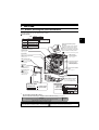
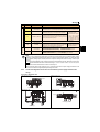
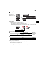
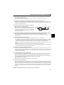
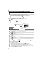
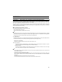
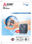
Product checking and parts identification
1 OUTLINE
1.1
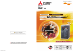
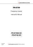
Product checking and parts identification
Unpack the inverter and check the capacity plate on the front cover and the rating plate on the inverter side face to ensure that
the product agrees with your order and the inverter is intact.
zInverter model
FR - E740 - 3.7 K
No.
Voltage class
E720
Three-phase 200V class
E740
Three-phase 400V class
E720S
Single-phase 200V class
E710W
Single-phase 100V class
1
Represents the
inverter capacity [kW]
Control logic switchover jumper
connector
The jumper connector is in the sink logic
(SINK) when shipped from the factory.
Move the jumper connector to change to
the source logic (SOURCE). Always fit the
jumper connector to the either position.
Cooling fan
The cooling fan is removable.
Operation panel
(Refer to page 2)
(
Refer to the Instruction Manual (Applied))
PU connector
(Refer to page 9)
USB connector
(mini-B connector)
(Refer to page 9)
Voltage/current input switch
(Refer to page 9)
USB connector cover
Refer to the Instruction
Manual (Applied) for how to
open the cover.
Connector for plug-in
option connection
(Refer to the instruction
manual of options.)
Front cover
Refer to the Instruction
Manual (Applied) for
installation/removal.
Control circuit terminal
block
(Refer to page 10)
PU connector cover
Refer to the
Instruction Manual
(Applied) for how to
open the cover.
Main circuit terminal block
(Refer to page 10)
Combed shaped wiring cover
Refer to the Instruction Manual
(Applied) for installation/removal.
Example of FR-E740-3.7K
Capacity plate
FR-E740-3.7K
Rating plate
Inverter model
Serial number
FR-E740-3.7K
Inverter model
Input rating
Output rating
Serial number
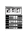
• Accessory
· Fan cover fixing screws (M3 × 35mm)
These screws are necessary for compliance with the EU Directive (Refer to page 47)
Capacity
Quantity
FR-E720-1.5K to 3.7K, FR-E740-1.5K to 3.7K, FR-E720S-0.75K to 2.2K
FR-E720-5.5K to 15K, FR-E740-5.5K to 15K
1
2
Harmonic suppression guideline (when inverters are used in Japan)
All models of general-purpose inverters used by specific consumers are covered by "Harmonic suppression guideline for consumers who
receive high voltage or special high voltage". (For further details,
refer to Chapter 3 of the Instruction Manual (Applied).)
1
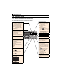
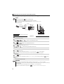
Operation panel
1.2
1.2.1
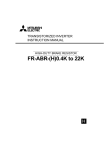
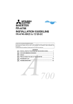
Operation panel
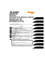
Names and functions of the operation panel
The operation panel cannot be removed from the inverter.
Operation mode indicator
PU: Lit to indicate PU operation mode.
EXT: Lit to indicate External operation mode.
(Lit at power-ON at initial setting.)
NET: Lit to indicate Network operation
mode.
PU, EXT: Lit to indicate External/PU
combined operation mode 1, 2.
These turn OFF when command source is
not on operation panel.
Operating status indicator
Lit or flicker during inverter operation. ∗
* Lit: When the forward rotation operation
is being performed.
Slow flickering (1.4s cycle):
When the reverse operation is being
performed.
Fast flickering (0.2s cycle):
When
was pressed or the
start command was given, but the
Unit indicator
Hz: Lit to indicate frequency.
(Flickers when the set frequency
monitor is displayed.)
A: Lit to indicate current.
(Both "Hz" and "A" turn OFF when other
than the above is displayed.)
Monitor (4-digit LED)
Shows the frequency, parameter number,
etc.
Setting dial
(Setting dial: Mitsubishi inverter dial)
Used to change the frequency setting and
parameter settings.
Press to display the following.
y Displays the set frequency in the
monitor mode
y Present set value is displayed during
calibration
y Displays the order in the faults history
mode
Mode switchover
Used to change each setting mode.
Pressing
simultaneously changes
operation cannot be made.
yWhen the frequency command is less
than the starting frequency.
yWhen the MRS signal is input.
Parameter setting mode
Lit to indicate parameter setting mode.
Monitor indicator
Lit to indicate monitoring mode.
Stop operation
Used to stop Run command.
Fault can be reset when protective
function is activated (fault).
Operation mode switchover
Used to switch between the PU and
External operation mode.
When using the External operation mode
(operation using a separately connected
frequency setting potentiometer and start
signal), press this key to light up the EXT
indication.
(Press
simultaneously (0.5s) or
change Pr. 79 setting to change to
operation. (
Refer to the Instruction
Manual (Applied))
combined mode .) (
Refer to the
Instruction Manual (Applied))
PU: PU operation mode
EXT: External operation mode
Cancels PU stop also.
Determination of each setting
If pressed during operation, monitor
changes as below:
Start command
The rotation direction can be selected by
setting Pr. 40.
the operation mode.
Pressing for a while (2s) can lock
Running frequency
Output current
Output voltage
2
Operation panel
1.2.2
Basic operation (factory setting)
Operation mode switchover
At power-ON (External operation mode)
1
Parameter setting
Monitor/frequency setting
PU Jog operation mode
(Example)
PU operation mode
(output frequency monitor)
Value change
and frequency flicker.
Frequency setting has been
written and completed!!
Output current monitor
STOP
Output voltage monitor
Display the
present setting
Parameter setting mode
(Example)
Parameter and a setting value
flicker alternately.
Parameter write is completed!!
Value change
Parameter clear
All parameter
clear
Faults history clear
Faults history
Initial value
change list
[Operation for displaying faults history] (Refer to page 38)
Past eight faults can be displayed.
(The latest fault is ended by ".".)
When no fault history exists,
is displayed.
While a fault is displayed:
The
display shifts as follows by pressing
Output current
Output voltage
: Output frequency at the fault
Energization time.
(After Energization time, it goes back to a fault display.)
Pressing
the setting dial shows the fault history number.
3
Operation panel
1.2.3
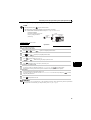
Changing the parameter setting value
Changing
example
Change the Pr. 1 Maximum frequency setting.
Operation
1. Screen at power-ON
Display
The monitor display appears.
2. Press
to choose the PU operation mode.
3. Press
to choose the parameter setting
PU indicator is lit.
PRM indicator is lit.
mode.
(The parameter number read previously appears.)
4. Turn
until
5. Press
"
(Pr. 1) appears.
to read the currently set value.
"(120.0Hz (initial value)) appears.
6. Turn
"
to change the set value to
" (60.00Hz).
7. Press
to set.
Flicker...Parameter setting complete!!
y Turn
to read another parameter.
y Press
to show the setting again.
y Press
twice to show the next parameter.
y Press
twice to return the monitor to frequency monitor.
REMARKS
to
is displayed...Why?
appears .................... Write disable error
appears .................... Write error during operation
appears .................... Calibration error
appears .................... Mode designation error
(For details,
Refer to the Instruction Manual (Applied).)
y The number of digits displayed on the operation panel is four. Only the upper four digits of values can be displayed and set. If the
values to be displayed have five digits or more including decimal places, the fifth or later numerals can not be displayed nor set.
(Example) For Pr. 1
When 60Hz is set, 60.00 is displayed.
When 120Hz is set, 120.0 is displayed and second decimal place is not displayed nor set.
4
Operation panel
1.2.4
Parameter clear/all parameter clear
POINT
y Set "1" in Pr.CL Parameter clear, ALLC all parameter clear to initialize all parameters. (Parameters are not cleared
when "1" is set in Pr. 77 Parameter write selection.)
y Refer to the extended parameter list of
operation.
the Instruction Manual (Applied) for parameters cleared with this
Operation
1. Screen at power-ON
Display
1
The monitor display appears.
2. Press
to choose the PU operation mode.
3. Press
to choose the parameter setting
PU indicator is lit.
PRM indicator is lit.
mode.
(The parameter number read previously appears.)
4. Turn
until
(
Parameter clear
) appears.
All parameter clear
5. Press
"
to read the currently set value.
"(initial value) appears.
6. Turn
to change it to the set value "
7. Press
".
Parameter clear
to set.
All parameter clear
Flicker ··· Parameter setting complete!!
y Turn
to read another parameter.
y Press
to show the setting again.
y Press
twice to show the next parameter.
Setting
0
Description
Not executed.
Sets parameters back to the initial values. (Parameter clear sets back all parameters except
1
calibration parameters and terminal function selection parameters to the initial values.) Refer to the
parameter list of
the Instruction Manual (Applied) for availability of parameter clear and all
parameter clear.
REMARKS
and
are displayed alternately ... Why?
The inverter is not in the PU operation mode.
PU connector or USB connector is used.
1. Press
. [PU] is lit and the monitor (4-digit LED) displays "1". (When Pr. 79 = "0" (initial value))
2. Carry out operation from step 6 again.
5
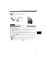
2 INSTALLATION AND WIRING
AC power supply
Use within the permissible power supply
specifications of the inverter. To ensure
safety, use a moulded case circuit breaker,
earth leakage circuit breaker or magnetic
contactor to switch power ON/OFF.
Enclosure surface
operation panel
(FR-PA07)
(Refer to page 44)
Moulded case circuit breaker
(MCCB) or earth leakage circuit
breaker (ELB), fuse
The breaker must be selected carefully
since an in-rush current flows in the
inverter at power ON.
USB connector
A personal computer and an inverter
can be connected with a
USB (Ver1. 1) cable.
Parameter unit
(FR-PU07)
(
Refer to Chapter 3 of the
Instruction Manual (Applied))
By connecting the connection
cable (FR-CB2) to the PU
connector, operation can be
performed from FR-PU07,
FR-PA07.
(Refer to page 7)
Magnetic contactor (MC)
Install the magnetic contactor to ensure
safety. Do not use this magnetic contactor
to start and stop the inverter. Doing so will
cause the inverter life to be shorten.
(Refer to page 7)
Reactor (FR-HAL, FR-HEL option)
Reactors (option) must be used when
power harmonics measures are taken,
the power factor is to be improved or the
inverter is installed near a large power
supply system (500kVA or more). The
inverter may be damaged if you do not
use reactors. Select the reactor according
to the model. Remove the jumpers across
terminals P/+ and P1 to connect the DC reactor.
AC reactor (FR-HAL)
Brake resistor
(FR-ABR, MRS type, MYS type)
Braking capability can be improved. (0.4K
or higher)
Always install a thermal relay when using
a brake resistor whose capacity is 11K or
higher. (Refer to page 17)
DC reactor (FR-HEL) *
EMC filter (ferrite core) *
(FR-BSF01, FR-BLF)
Install an EMC filter (ferrite core)
to reduce the electromagnetic
noise generated from the
inverter. Effective in the range
from about 1MHz to 10MHz.
When more wires are passed
through, a more effective result
can be obtained. A wire should
be wound four turns or more.
P/+ P1
P/+
PR
Inverter (FR-E700)
R/L1 S/L2 T/L3
Earth (Ground)
EMC filter
(capacitor) *
(FR-BIF)
P/+ N/-
Reduces the
radio noise.
U VW
EMC filter (ferrite core)
(FR-BSF01, FR-BLF)
Install an EMC filter (ferrite core)
to reduce the electromagnetic
noise generated from the inverter.
Effective in the range from about
1MHz to 10MHz. A wire should be
wound four turns at a maximum.
Motor
* Filterpack (FR-BFP2), which contains DC reactor and EMC filter in one package, is also available.
Brake unit
(FR-BU2)
P/+ PR
P/+
PR
High power factor
converter (FR-HC)
Power supply harmonics
can be greatly suppressed.
Install this as required.
NOTE
Power regeneration
common converter
(FR-CV)
Great braking capability
is obtained.
Install this as required.
Resistor unit (FR-BR)
Discharging resistor (GZG, GRZG)
The regenerative braking capability
of the inverter can be exhibited fully.
Install this as required.
Devices connected to the output Earth (Ground)
Do not install a power factor correction capacitor,
surge suppressor or capacitor type filter on the output
side of the inverter. When installing a moulded case
circuit breaker on the output side of the inverter,
contact each manufacturer for selection of the
moulded case circuit breaker.
Earth (Ground)
To prevent an electric shock, always earth (ground)
the motor and inverter. For reduction of induction noise
from the power line of the inverter, it is recommended
to wire the earthing cable by returning it to the earth
(ground) terminal of the inverter.
y The life of the inverter is influenced by surrounding air temperature. The surrounding air temperature should be as low as
possible within the permissible range. This must be noted especially when the inverter is installed in an enclosure. (Refer
to page 8)
y Wrong wiring might lead to damage of the inverter. The control signal lines must be kept fully away from the main circuit
to protect them from noise. (Refer to page 9)
y Do not install a power factor correction capacitor, surge suppressor or capacitor type filter on the inverter output side.
This will cause the inverter to trip or the capacitor and surge suppressor to be damaged. If any of the above devices are
connected, immediately remove them.
y Electromagnetic wave interference
The input/output (main circuit) of the inverter includes high frequency components, which may interfere with the
communication devices (such as AM radios) used near the inverter. In this case, install options among the capacitor type
EMC filter FR-BIF (for use in the input side only), the ferrite core type EMC filter FR-BSF01/FR-BLF, filterpack, and EMC
filter to minimize the interference. (
Refer to Chapter 3 of the Instruction Manual (Applied)).
y Refer to the instruction manual of each option and peripheral devices for details of peripheral devices.
6
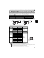
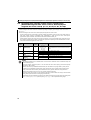
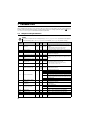
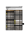
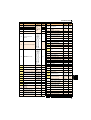
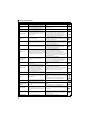
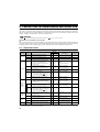
Peripheral devices
2.1
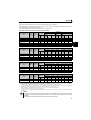
Peripheral devices
Check the inverter model of the inverter you purchased. Appropriate peripheral devices must be selected according to the capacity.
Refer to the following list and prepare appropriate peripheral devices.
Applicable Inverter
Single-Phase 100V Single-Phase 200V
Three-Phase 400V
Three-Phase 200V
Model
∗1
Motor
Output
(kW)
Moulded Case Circuit Breaker
(MCCB) ∗1
or Earth Leakage Circuit Breaker
(ELB) ∗2
Reactor connection
without
with
Magnetic Contactor (MC)
Reactor connection
without
with
FR-HAL
FR-HEL
FR-E720-0.1K
0.1
5A
5A
S-N10
S-N10
0.4K ∗5
0.4K ∗5
FR-E720-0.2K
FR-E720-0.4K
FR-E720-0.75K
FR-E720-1.5K
FR-E720-2.2K
FR-E720-3.7K
FR-E720-5.5K
FR-E720-7.5K
FR-E720-11K
FR-E720-15K
FR-E740-0.4K
FR-E740-0.75K
FR-E740-1.5K
FR-E740-2.2K
FR-E740-3.7K
FR-E740-5.5K
FR-E740-7.5K
FR-E740-11K
FR-E740-15K
FR-E720S-0.1K
0.2
0.4
0.75
1.5
2.2
3.7
5.5
7.5
11
15
0.4
0.75
1.5
2.2
3.7
5.5
7.5
11
15
0.1
5A
5A
10A
15A
20A
30A
50A
60A
75A
125A
5A
5A
10A
15A
20A
30A
30A
50A
60A
5A
5A
5A
10A
15A
15A
30A
40A
50A
75A
100A
5A
5A
10A
10A
15A
20A
30A
40A
50A
5A
S-N10
S-N10
S-N10
S-N10
S-N10
S-N20, S-N21
S-N25
S-N25
S-N35
S-N50
S-N10
S-N10
S-N10
S-N10
S-N10
S-N20, S-N21
S-N20, S-N21
S-N20, S-N21
S-N25
S-N10
S-N10
S-N10
S-N10
S-N10
S-N10
S-N10
S-N20, S-N21
S-N25
S-N35
S-N50
S-N10
S-N10
S-N10
S-N10
S-N10
S-N11, S-N12
S-N20, S-N21
S-N20, S-N21
S-N20, S-N21
S-N10
0.4K ∗5
0.4K
0.75K
1.5K
2.2K
3.7K
5.5K
7.5K
11K
15K
H0.4K
H0.75K
H1.5K
H2.2K
H3.7K
H5.5K
H7.5K
H11K
H15K
0.4K ∗5
0.4K ∗5
0.4K
0.75K
1.5K
2.2K
3.7K
5.5K
7.5K
11K
15K
H0.4K
H0.75K
H1.5K
H2.2K
H3.7K
H5.5K
H7.5K
H11K
H15K
0.4K ∗5
FR-E720S-0.2K
0.2
5A
5A
S-N10
S-N10
0.4K ∗5
0.4K ∗5
FR-E720S-0.4K
0.4
10A
10A
S-N10
S-N10
0.75K ∗5
0.75K ∗5
FR-E720S-0.75K
0.75
15A
10A
S-N10
S-N10
1.5K ∗5
1.5K ∗5
FR-E720S-1.5K
1.5
20A
20A
S-N10
S-N10
2.2K ∗5
2.2K ∗5
FR-E720S-2.2K
2.2
40A
30A
S-N20, S-N21
S-N10
3.7K ∗5
3.7K ∗5
FR-E710W-0.1K
0.1
10A
5A
S-N10
S-N10
0.75K ∗4, ∗5
−−− ∗6
FR-E710W-0.2K
0.2
10A
10A
S-N10
S-N10
1.5K ∗4, ∗5
−−− ∗6
FR-E710W-0.4K
0.4
15A
15A
S-N10
S-N10
2.2K ∗4, ∗5
−−− ∗6
FR-E710W-0.75K
0.75
30A
20A
S-N10
S-N10
3.7K ∗4, ∗5
−−− ∗6
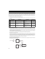
ySelect an MCCB according to the power supply capacity.
yInstall one MCCB per inverter.
∗2
Reactor
∗3
MCCB
INV
IM
MCCB
INV
IM
2
For the use in the United States or Canada, select a UL and cUL certified fuse with Class T fuse equivalent cut-off
speed or faster with the appropriate rating for branch circuit protection. Alternatively, select a UL489 molded case circuit breaker (MCCB). (Refer to page 50)
∗3
Magnetic contactor is selected based on the AC-1 class. The electrical durability of magnetic contactor is 500,000 times. When the magnetic contactor is
used for emergency stop during motor driving, the electrical durability is 25 times.
When using the MC for emergency stop during motor driving or using on the motor side during commercial-power supply operation, select the MC with class
AC-3 rated current for the motor rated current.
∗4
When connecting a single-phase 100V power input inverter to a power transformer (50kVA or more), install a AC reactor (FR-HAL) so that the performance
∗5
is more reliable. (
Refer to Chapter 3 of the Instruction Manual (Applied))
The power factor may be slightly lower.
∗6
Single-phase 100V power input model is not compatible with DC reactor.
NOTE
y When the inverter capacity is larger than the motor capacity, select an MCCB and a magnetic contactor according to
the inverter model and cable and reactor according to the motor output.
y When the breaker on the inverter input side trips, check for the wiring fault (short circuit), damage to internal parts of
the inverter, etc. Identify the cause of the trip, then remove the cause and power ON the breaker.
7
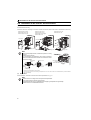
Installation of the inverter and instructions
2.2
(1)
Installation of the inverter and instructions
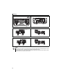
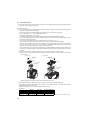
Installation of the inverter
Enclosure surface mounting
Remove the front cover and wiring cover to fix the inverter to the surface. (Remove the covers in the directions of the arrows.)
FR-E720-0.1K to 0.75K
FR-E720S-0.1K to 0.4K
FR-E710W-0.1K to 0.4K
FR-E720-1.5K to 3.7K
FR-E740-0.4K to 7.5K
FR-E720S-0.75K or higher
FR-E710W-0.75K
FR-E720-5.5K to 15K
FR-E740-11K, 15K
Front cover
Front cover
Front cover 1
Wiring cover
Wiring cover
Wiring cover
Note
y When encasing multiple inverters, install them in parallel as a cooling
measure.
y Install the inverter vertically.
shown in the table below from the inverter to the other devices and to
the enclosure surface.
5cm
Measurement
position
Measurement
position
5cm
5cm
1cm or
more ∗1, ∗2
Refer to the
clearances
shown on
the left.
10cm or more
1cm or
more ∗1, ∗2
10cm or more
Vertical
y For heat dissipation and maintenance, take at least the clearances
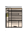
1cm or
more ∗1
-10 C to +50 C
(non-freezing)
∗1
∗2
Take 5cm or more clearances for 5.5K or higher.
When using the inverters at the surrounding air temperature of 40°C or less, the inverters can be installed without any clearance between
them (0cm clearance).
(2)
Environment
Before installation, check that the environment meets the specifications on page 45.
Note
y Install the inverter on a strong surface securely and vertically with bolts.
y Leave enough clearances and take cooling measures.
y Avoid places where the inverter is subjected to direct sunlight, high temperature and high humidity.
y Install the inverter on a nonflammable wall surface.
8
Wiring
2.3
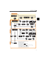
Wiring
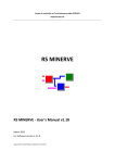
2.3.1
Terminal connection diagram
*1. DC reactor (FR-HEL)
Sink logic
Main circuit terminal
Control circuit terminal
When connecting a DC reactor, remove the
jumper across P1 and P/+.
Not available for single-phase 100V power
input model.
Single-phase power input
MCCB
*7 A brake transistor is not built-in to the 0.1K
and 0.2K.
Brake unit
(Option)
MC
Single-phase
AC power
supply
R/L1
S/L2
*1
Earth
(Ground)
*8
PR N/-
P1
*6
MC
R/L1
S/L2
T/L3
Three-phase
AC power
supply
*8 Brake resistor (FR-ABR, MRS, MYS type)
Install a thermal relay to prevent an
overheat and burnout of the brake resistor.
(The brake resistor can not be connected
to the 0.1K and 0.2K.)
R
Jumper
MCCB
*6 Terminal P1 is not available for singlephase 100V power input model.
Earth
(Ground)
P/+
*7
Motor
U
V
W
IM
2
Main circuit
Earth (Ground)
Control circuit
Standard control terminal block
Control input signals (No voltage input allowed)
Forward
Terminal functions vary rotation start
with the input terminal Reverse
assignment (Pr. 178 to rotation start
Pr. 184)
High
speed
Multi-speed selection Middle
speed
*2 When using terminals PC
Low
and SD as a 24VDC
speed
STF
B
STR
A
Open collector output
RM
RUN
RL
Running
MRS
RES
Reset
SD
Contact input common
24VDC power supply
(Common for external power supply transistor)
Frequency detection
SE
PC *2
Open collector output common
Sink/source common
Calibration resistor
+
Frequency setting signals (Analog)
10(+5V)
3
*3 Terminal input specifications Frequency
can be changed by analog setting
input specifications
potentiometer
switchover (Pr. 73).
1/2W1kΩ
*4 It is recommended to use 2W1kΩ *4
when the frequency setting signal
is changed frequently.
2
1
Terminal 4 input (+)
(Current input) (-)
*5 Terminal input specifications can be changed by analog
input specifications switchover (Pr. 267). Set the
voltage/current input switch in the "V" position to select
voltage input (0 to 5V/0 to10V) and "I" (initial value) to
select current input (4 to 20mA).
To use terminal 4 (initial setting is current input), set "4"
in any of Pr.178 to Pr.184 (input terminal function selection)
to assign the function, and turn ON AU signal.
FM
2 0 to 5VDC *3
(0 to 10VDC)
SD
5(Analog common)
PU
connector
4 4 to 20mADC
0 to 5VDC
0 to 10VDC *5
*10
I
*9
-
Indicator
(Frequency meter, etc.)
Moving-coil type
1mA full-scale
*9 It is not necessary when calibrating the
indicator from the operation panel.
*10 Operation and parameter setting can be
done from the parameter unit (FR-PU07)
and the enclosure surface operation panel
(FR-PA07).
(Use the option cable (FR-CB2 ).)
RS-485 communication can be utilized from
a personal computer and other devices.
V
Voltage/current
input switch *5
USB
connector
*11
Connector for
plug-in option connection
Terminal functions vary with
the output terminal assignment
(Pr. 190 and Pr. 191)
FU
SINK
Output
stop
Terminal functions vary
by Pr. 192 A,B,C terminal
function selection
Relay output
(Fault output)
RH
SOURCE
power supply, take care
not to short across
terminals PC and SD.
Relay output
C
*11 A personal computer and an inverter can be
connected with a USB (Ver1.1) cable.
You can perform parameter setting and
monitoring with the FR Configurator (FRSW3-SETUP-W ).
Option connector
NOTE
y To prevent a malfunction caused by noise, separate the signal cables more than 10cm from the power cables. Also
separate the main circuit wire of the input side and the output side.
y After wiring, wire offcuts must not be left in the inverter.
Wire offcuts can cause an alarm, failure or malfunction. Always keep the inverter clean. When drilling mounting holes
in an enclosure etc., take care not to allow chips and other foreign matter to enter the inverter.
y The output of the single-phase power input model is three-phase 200V.
9
Wiring
2.3.2
Main circuit
Type
Terminal specifications
Terminal
Symbol
Terminal Name
R/L1, S/L2,
T/L3 *
AC power input
U, V, W
Inverter output
P/+, PR
Brake resistor connection
P/+, N/-
P/+, P1 *
Description
Connect to the commercial power supply. Keep these terminals open when using the high
power factor converter (FR-HC) or power regeneration common converter (FR-CV).
∗ When using single-phase power input, terminals are R/L1 and S/L2.
Connect a three-phase squirrel-cage motor.
Connect a brake resistor (MRS type, MYS type, FR-ABR) across terminals P/+ and PR.
(The brake resistor can not be connected to the 0.1K or 0.2K)
Brake unit connection
Connect the brake unit (FR-BU2), power regeneration common converter (FR-CV) or high
power factor converter (FR-HC).
DC power input
Connect the plus side of the power supply to terminal P/+ and minus side to terminal N/-.
DC reactor connection
Remove the jumper across terminals P/+ and P1 and connect a DC reactor. Single-phase
100V power input model is not compatible with DC reactor.
∗ Terminal P1 is not available for single-phase 100V power input model.
Earth (Ground)
STF
Forward rotation start
STR
Reverse rotation start
RH, RM, RL
Multi-speed selection
MRS
Output stop
Control circuit/input signal
Contact input
RES
SD
External transistor
common (source)
PC
24VDC power supply
common
External transistor
common
(sink) (initial setting)
Contact input common
(source)
24VDC power supply
Frequency setting power
supply
10
2
Frequency setting
Reset
Contact input common
(sink) (initial setting)
4
Frequency setting
(voltage)
Frequency setting
(current)
For earthing (grounding) the inverter chassis. Must be earthed (grounded).
Turn ON the STF signal to start forward rotation and turn it OFF When the STF and STR
to stop.
signals are turned ON
Turn ON the STR signal to start reverse rotation and turn it OFF simultaneously, the stop
command is given.
to stop.
Multi-speed can be selected according to the combination of RH, RM and RL signals.
Turn ON the MRS signal (20ms or more) to stop the inverter output.
Use to shut off the inverter output when stopping the motor by electromagnetic brake.
Used to reset alarm output provided when protective circuit is activated. Turn ON the RES
signal for more than 0.1s, then turn it OFF. Initial setting is for reset always. By setting Pr. 75,
reset can be set to enabled only at fault occurrence. Recover about 1s after reset is cancelled.
Common terminal for contact input terminal (sink logic) and terminal FM.
Connect this terminal to the power supply common terminal of a transistor output (open
collector output) device, such as a programmable controller, in the source logic to avoid
malfunction by undesirable current.
Common output terminal for 24VDC 0.1A power supply (PC terminal).
Isolated from terminals 5 and SE.
Connect this terminal to the power supply common terminal of a transistor output (open
collector output) device, such as a programmable controller, in the sink logic to avoid
malfunction by undesirable current.
Common terminal for contact input terminal (source logic).
Can be used as 24VDC 0.1A power supply.
Used as power supply when connecting potentiometer for
frequency setting (speed setting) from outside of the inverter.
Inputting 0 to 5VDC (or 0 to 10V) provides the maximum output
Input resistance 10kΩ ± 1kΩ
frequency at 5V (10V) and makes input and output
Permissible maximum voltage
proportional. Use Pr. 73 to switch between input 0 to 5VDC
20VDC
(initial setting) and 0 to 10VDC input.
Inputting 0 to 20mADC (or 0 to 5V / 0 to 10V) provides the
maximum output frequency at 20mA and makes input and
output proportional. This input signal is valid only when the AU
signal is ON (terminal 2 input is invalid). To use terminal 4
(initial setting is current input), set "4" to any of Pr.178 to Pr.184
(input terminal function selection), and turn AU signal ON. Use
Pr. 267 to switch among input 4 to 20mA (initial setting), 0 to
5VDC, and 0 to 10VDC. Set the voltage/current input switch in
the "V" position to select voltage input (0 to 5V/0 to 10V).
Current input
(initial status)
5
10
Frequency setting
common
5VDC
permissible load current 10mA
Voltage input:
Input resistance 10kΩ ± 1kΩ
Permissible maximum voltage
20VDC
Current input:
Input resistance 233Ω ± 5Ω
Maximum permissible current
30mA.
Voltage input
Common terminal for the frequency setting signals (terminals 2 and 4). Do not earth (ground).
Wiring
Open collector
Communication
Pulse
Control circuit/output signal
Relay
Type
Terminal
Symbol
Terminal Name
A, B, C
Relay output
(fault output)
RUN
Inverter running
FU
Frequency detection
SE
Open collector
output common
FM
For meter
—
PU connector
—
USB connector
Description
1 changeover contact output indicates that the inverter fault occurs.
Fault: discontinuity across B-C (continuity across A-C), Normal: continuity across B-C
(discontinuity across A-C) Contact capacity 230VAC 0.3A (power factor = 0.4) 30VDC 0.3A
Switched Low when the inverter output frequency is equal to or Permissible load 24VDC
higher than the starting frequency (initial value 0.5Hz).
(Maximum 27VDC) 0.1A
Switched High during stop or DC injection brake operation.∗
(a voltage drop is 3.4V
maximum when the signal is
on)
Switched Low when the inverter output frequency is equal to or ∗ Low is when the open
higher than the preset detected frequency and High when less
collector output transistor is
ON (conducts). High is when
than the preset detected frequency.∗
the transistor is OFF (does
not conduct).
Common terminal of terminal RUN and FU.
Used to output a selected monitored item (such as Output
frequency) among several monitored items. (Not output during Permissible load current 1mA
inverter reset.) The output signal is proportional to the
1440 pulses/s at 60Hz
magnitude of the corresponding monitoring item.
With the PU connector, RS-485 communication can be established.
· Conforming standard: EIA-485 (RS-485)
· Transmission format: Multi-drop link
· Communication speed: 4800 to 38400bps · Overall extension: 500m
FR Configurator can be operated by connecting the inverter to the personal computer through USB.
· Interface: conforms to USB1.1
· Transmission Speed: 12Mbps
· Connector: USB mini B connector (receptacle mini B type)
Note
y Set Pr. 267 and a voltage/current input switch correctly, then input an analog signal in accordance with the setting.
Applying a voltage with voltage/current input switch in "I" position (current input is selected) or a current with switch
in "V" position (voltage input is selected) could cause component damage of the inverter or analog circuit of output
devices.
y The inverter will be damaged if power is applied to the inverter output terminals (U, V, W). Never perform such wiring.
y
indicates that terminal functions can be selected using Pr. 178 to Pr. 184 and Pr. 190 to Pr. 192 (I/O terminal function
selection).
y Terminal names and terminal functions are those of the factory set.
y When connecting the DC power supply, be sure to connect the plus side of the power supply to terminal P/+ and
minus side to terminal N/-. Opposite polarity will damage the inverter.
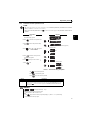
2.3.3
Terminal arrangement of the main circuit terminal, power supply and the motor
wiring
Three-phase 200V/400V class
FR-E720-0.1K to 0.75K
FR-E720-1.5K to 3.7K
FR-E740-0.4K to 3.7K
Jumper
N/-
P/+
N/- P/+
Jumper
R/L1 S/L2 T/L3
PR
R/L1 S/L2 T/L3
PR
IM
IM
Power supply
Motor
Power supply
Motor
FR-E720-5.5K, 7.5K
FR-E740-5.5K, 7.5K
R/L1 S/L2 T/L3
R/L1 S/L2 T/L3
Jumper
N/-
P/+ PR
N/-
P/+ PR
Jumper
IM
Power supply Motor
IM
Power supply
Motor
11
2
Wiring
FR-E720-11K, 15K
FR-E740-11K, 15K
N/-
R/L1
S/L2 T/L3
N/-
P/+
P/+ PR R/L1 S/L2 T/L3
PR
Jumper
IM
Jumper
Power supply
Motor
IM
Power supply
Motor
Single-phase 200V class
FR-E720S-0.1K to 0.4K
FR-E720S-0.75K to 2.2K
Jumper
N/-
P/+
N/- P/+
Jumper
R/L1 S/L2
PR
R/L1 S/L2
PR
IM
IM
Power supply
Power supply
Motor
Motor
Single-phase 100V class
FR-E710W-0.1K to 0.4K
FR-E710W-0.75K
N/- P/+
N/-
P/+
PR
R/L1 S/L2
IM
Power supply
R/L1 S/L2
PR
Motor
IM
Power supply
Motor
NOTE
y Make sure the power cables are connected to the R/L1, S/L2, and T/L3. (Phase need not be matched.) Never connect
the power cables to the U, V, and W of the inverter. Doing so will damage the inverter.
y Connect the motor to U, V, and W. Turning ON the forward rotation switch (signal) at this time rotates the motor
counterclockwise when viewed from the load shaft.
12
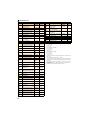
Wiring
(1)
Cable size and other specifications of the main circuit terminals and the earthing terminal
Select the recommended cable size to ensure that a voltage drop will be 2% at maximum.
If the wiring distance is long between the inverter and motor, a main circuit cable voltage drop will cause the motor torque to
decrease especially at the output of a low frequency.
The following table indicates a selection example for the wiring length of 20m.
Three-phase 200V class (when input power supply is 220V)
Applicable Inverter
Model
FR-E720-0.1K to 0.75K
Cable Size
Crimping
Terminal
Terminal Tightening
AWG ∗2
HIV Cables, etc. (mm2) ∗1
Screw
Torque
R/L1
R/L1
R/L1
Size ∗4
Earthing
N·m
S/L2 U, V, W S/L2 U, V, W cable
S/L2 U, V, W
T/L3
T/L3
T/L3
PVC Cables, etc. (mm2) ∗3
R/L1
S/L2 U, V, W Earthing
cable
T/L3
M3.5
1.2
2-3.5
2-3.5
2
2
2
14
14
2.5
2.5
2.5
FR-E720-1.5K, 2.2K
M4
1.5
2-4
2-4
2
2
2
14
14
2.5
2.5
2.5
FR-E720-3.7K
M4
1.5
5.5-4
5.5-4
3.5
3.5
3.5
12
12
4
4
4
FR-E720-5.5K
M5
2.5
5.5-5
5.5-5
5.5
5.5
5.5
10
10
6
6
6
FR-E720-7.5K
M5
2.5
14-5
8-5
14
8
5.5
6
8
16
10
6
FR-E720-11K
M5
2.5
14-5
14-5
14
14
14
6
6
16
16
16
FR-E720-15K
M6(M5)
4.4
22-6
22-6
22
22
14
4
4
25
25
16
2
Three-phase 400V class (when input power supply is 440V)
Applicable Inverter
Model
Cable Size
Crimping
Terminal
Terminal Tightening
AWG ∗2
HIV Cables, etc. (mm2) ∗1
Screw
Torque
R/L1
R/L1
R/L1
Earthing
Size ∗4
N·m
S/L2 U, V, W S/L2 U, V, W cable
S/L2 U, V, W
T/L3
T/L3
T/L3
PVC Cables, etc. (mm2) ∗3
R/L1
S/L2 U, V, W Earthing
cable
T/L3
FR-E740-0.4K to 3.7K
M4
1.5
2-4
2-4
2
2
2
14
14
2.5
2.5
FR-E740-5.5K
M4
1.5
5.5-4
2-4
3.5
2
3.5
12
14
4
2.5
2.5
4
FR-E740-7.5K
M4
1.5
5.5-4
5.5-4
3.5
3.5
3.5
12
12
4
4
4
FR-E740-11K
M4
1.5
5.5-4
5.5-4
5.5
5.5
8
10
10
6
6
10
FR-E740-15K
M5
2.5
8-5
8-5
8
8
8
8
8
10
10
10
Single-phase 200V class (when input power supply is 220V)
Applicable Inverter
Model
FR-E720S-0.1K to 0.4K
FR-E720S-0.75K
Cable Size
Crimping
Terminal Tightening
Terminal
AWG ∗2
HIV Cables, etc. (mm2) ∗1
PVC Cables, etc. (mm2) ∗3
Screw
Torque
R/L1 U, V, W R/L1 U, V, W Earthing R/L1 U, V, W R/L1 U, V, W Earthing
Size ∗4
N·m
S/L2
S/L2
cable
S/L2
S/L2
cable
M3.5
1.2
2-3.5
2-3.5
2
2
2
14
14
2.5
2.5
2.5
M4
1.5
2-4
2-4
2
2
2
14
14
2.5
2.5
2.5
FR-E720S-1.5K
M4
1.5
2-4
2-4
2
2
2
14
14
2.5
2.5
2.5
FR-E720S-2.2K
M4
1.5
5.5-4
2-4
3.5
2
2
12
14
4
2.5
2.5
Single-phase 100V class (when input power supply is 100V)
Applicable Inverter
Model
FR-E710W-0.1K to 0.4K
FR-E710W-0.75K
∗1
∗2
∗3
∗4
Cable Size
Crimping
Terminal Tightening
2
Terminal
AWG ∗2
HIV
Cables,
etc.
(mm
)
∗1
PVC Cables, etc. (mm2) ∗3
Screw
Torque
Size ∗4
N·m
R/L1 U, V, W R/L1 U, V, W Earthing R/L1 U, V, W R/L1 U, V, W Earthing
S/L2
S/L2
cable
S/L2
S/L2
cable
M3.5
1.2
2-3.5
2-3.5
2
2
2
14
14
2.5
2.5
2.5
M4
1.5
5.5-4
2-4
3.5
2
2
14
14
2.5
2.5
2.5
The cable size is that of the cable (HIV cable (600V class 2 vinyl-insulated cable) etc.) with continuous maximum permissible temperature of 75°C. Assumes
that the surrounding air temperature is 50°C or less and the wiring distance is 20m or less.
The recommended cable size is that of the cable (THHW cable) with continuous maximum permissible temperature of 75°C. Assumes that the surrounding air
temperature is 40°C or less and the wiring distance is 20m or less. (Selection example for use mainly in the United States.)
The recommended cable size is that of the cable (PVC cable) with continuous maximum permissible temperature of 70°C. Assumes that the surrounding air
temperature is 40°C or less and the wiring distance is 20m or less. (Selection example for use mainly in Europe.)
The terminal screw size indicates the terminal size for R/L1, S/L2, T/L3, U, V, W, and a screw for earthing (grounding).
A screw for earthing (grounding) of the FR-E720-15K is indicated in ( ).
For single-phase power input, the terminal screw size indicates the size of terminal screw for R/L1, S/L2, U, V, W, PR, P/+, N/-, P1 and a screw for earthing
(grounding).
NOTE
y Tighten the terminal screw to the specified torque. A screw that has been tighten too loosely can cause a short circuit
or malfunction. A screw that has been tighten too tightly can cause a short circuit or malfunction due to the unit
breakage.
y Use crimping terminals with insulation sleeve to wire the power supply and motor.
13
Wiring
The line voltage drop can be calculated by the following formula:
3 × wire resistance[mΩ/m] × wiring distance[m] × current[A]
1000
Use a larger diameter cable when the wiring distance is long or when it is desired to decrease the voltage drop (torque
Line voltage drop [V]=
reduction) in the low speed range.
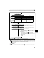
(2)
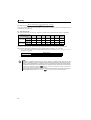
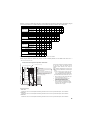
Total wiring length
The overall wiring length for connection of a single motor or multiple motors should be within the value in the table below.
Pr. 72 PWM frequency selection
Setting
(carrier frequency)
100V class,
1 (1kHz) or less
200V class
400V class
100V class,
2 to15
(2kHz to 14.5kHz)
200V class
400V class
0.1K
0.2K
0.4K
0.75K
1.5K
2.2K
3.7K
or Higher
200m
200m
300m
500m
500m
500m
500m
-
-
200m
200m
300m
500m
500m
30m
100m
200m
300m
500m
500m
500m
-
-
30m
100m
200m
300m
500m
When driving a 400V class motor by the inverter, surge voltages attributable to the wiring constants may occur at the
motor terminals, deteriorating the insulation of the motor. Take the following measures 1) or 2) in this case.
1) Use a "400V class inverter-driven insulation-enhanced motor" and set frequency in Pr. 72 PWM frequency selection
according to wiring length.
50m or less
Carrier frequency
14.5kHz or less
Wiring Length
50m to 100m
8kHz or less
Exceeding 100m
2kHz or less
2) Connect the surge voltage suppression filter (FR-ASF-H/FR-BMF-H) on the inverter output side.
NOTE
y Especially for long-distance wiring, the inverter may be affected by a charging current caused by the stray
capacitances of the wiring, leading to a malfunction of the overcurrent protective function, fast response current limit
function, or stall prevention function or a malfunction or fault of the equipment connected on the inverter output side.
If malfunction of fast-response current limit function occurs, disable this function. If malfunction of stall prevention
function occurs, increase the stall level. (
Refer to Pr. 22 Stall prevention operation level and Pr. 156 Stall prevention
operation selection in Chapter 4 of the Instruction Manual (Applied))
y When using the automatic restart after instantaneous power failure function with the wiring length exceeding 100m,
select without frequency search (Pr. 162 = "1, 11"). (
14
Refer to Chapter 4 of the Instruction Manual (Applied))
Wiring
2.3.4
Wiring of control circuit
z Terminal layout
Terminal screw size
M3: (Terminal A, B, C)
M2: (Other than the above)
10
2
5
4 RUN FU SE
FM RL RM RH MRS RES SD PC STF STR SD SD
A
B
C
2
z Wiring method
1) Strip off the sheath of the wire of the control circuit to wire.
Strip off the sheath about the length below. If the length of the sheath peeled is too long, a short circuit may occur
among neighboring wires. If the length is too short, wires might come off.
Wire the stripped wire after twisting it to prevent it from becoming loose. In addition, do not solder it. Use a blade
terminal as necessary.
Wire stripping length
L
L(mm)
Terminal A, B, C
Other than the above
6
5
Blade terminals available on the market: (as of Jan. 2010)
zPhoenix Contact Co.,Ltd.
Terminal Screw Size
M3 (terminal A, B, C)
M2 (other than the above)
Wire Size (mm2)
Blade Terminal Model
With Insulation Sleeve
Without Insulation Sleeve
Blade terminal
crimping tool
0.3, 0.5
AI 0,5-6WH
A 0,5-6
0.75
AI 0,75-6GY
A 0,75-6
0.3, 0.5
AI 0,5-6WH
A 0,5-6
Wire Size (mm2)
Blade terminal product
number
Insulation product number
Blade terminal
crimping tool
0.3 to 0.75
BT 0.75-7
VC 0.75
NH 67
CRIMPFOX 6
zNICHIFU Co.,Ltd.
Terminal Screw Size
M3 (terminal A, B, C)
M2 (other than the above)
2) Loosen the terminal screw and insert the wire into the terminal.
3) Tighten the screw to the specified torque.
Undertightening can cause wire disconnection or malfunction. Overtightening can cause a short circuit or malfunction due
to damage to the screw or unit.
Tightening torque: 0.5N·m to 0.6N·m (terminal A, B, C)
0.22N·m to 0.25N·m (other than the above)
Screwdriver:
Small flathead screwdriver (Tip thickness: 0.4mm/tip width: 2.5mm)
15
Wiring
(1)
Control circuit common terminals (SD, 5, SE)
Terminals SD, SE and 5 are common terminals for I/O signals. (All common terminals are isolated from each other.) Do not
earth them. Avoid connecting the terminals SD and 5 and the terminals SE and 5.
Terminal SD is a common terminal for the contact input terminals (STF, STR, RH, RM, RL, MRS, RES) and frequency output
signal (FM). The open collector circuit is isolated from the internal control circuit by photocoupler.
Terminal 5 is a common terminal for the frequency setting signals (terminal 2 or 4). It should be protected from external noise
using a shielded or twisted wire.
Terminal SE is a common terminal for the open collector output terminal (RUN, FU). The contact input circuit is isolated from
the internal control circuit by photocoupler.
(2)
Wiring instructions
1) It is recommended to use the wires of 0.3mm2 to 0.75mm2 gauge for connection to the control circuit terminals.
2) The maximum wiring length should be 30m (200m for terminal FM).
3) Do not short terminals PC and SD. Inverter may be damaged.
4) Use two or more parallel micro-signal contacts or twin contacts to prevent
contact faults when using contact inputs since the control circuit input signals
are micro-currents.
5) Use shielded or twisted wires for connection to the control circuit terminals and
run them away from the main and power circuits (including the 200V relay
sequence circuit).
Micro signal contacts
Twin contacts
6) Do not apply a voltage to the contact input terminals (e.g. STF) of the control
circuit.
7) Always apply a voltage to the fault output terminals (A, B, C) via a relay coil, lamp, etc.
16
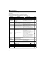
Connection of a dedicated external brake resistor (MRS type, MYS type, FR-ABR)
2.4
Connection of a dedicated external brake resistor (MRS type,
MYS type, FR-ABR)
Install a dedicated brake resistor (MRS type, MYS type, FR-ABR) outside when the motor driven by the inverter is made to run
by the load, quick deceleration is required, etc. Connect a dedicated brake resistor (MRS type, MYS type, FR-ABR) to
terminal P/+ and PR. (For the locations of terminal P/+ and PR, refer to the terminal block layout (page 11).)
Set parameters below. (
Refer to the Instruction Manual (Applied) for the parameter details.)
Connected Brake Resistor
Pr. 30 Regenerative function selection Setting
MRS type, MYS type
MYS type
(used at 100% torque/6%ED)
0 (initial value)
Pr. 70 Special regenerative brake duty Setting
—
1
6%
FR-ABR
1
7.5K or lower
11K or higher
10%
6%
It is recommended to configure a sequence, which shuts off power in the input side of the inverter by the external thermal
relay as shown below, to prevent overheat and burnout of the brake resistor (MRS, MYS) and high duty brake resistor (FRABR) in case the regenerative brake transistor is damaged. (The brake resistor can not be connected to the 0.1K or 0.2K.)
<Example 1>
MC
Power supply
Thermal relay
(OCR) (*1)
Inverter
R/L1
P/+
S/L2
T/L3
PR
High-duty brake
resistor (FR-ABR)
R
<Example 2>
MC
Power supply
F
ON
MC
2
High-duty brake
resistor (FR-ABR)
R
T *2
T *2
F
OFF
Thermal relay
(OCR) (*1)
Inverter
P/+
R/L1
S/L2
PR
T/L3
MC
ON
OCR
Contact
B
OFF
MC
MC
OCR
Contact
C
∗1
Refer to the table below for the type number of each capacity of thermal relay and the diagram below for the connection.
∗2
When the power supply is 400V class, install a step-down transformer.
(Always install a thermal relay when using a brake resistor whose capacity is 11K or higher)
Power Supply
Voltage
100V, 200V
Brake Resistor
TH-N20CXHZ-0.7A
MRS120W100
TH-N20CXHZ-1.3A
110VAC 5A,
MRS120W60
TH-N20CXHZ-2.1A
220VAC 2A (AC11 class)
MRS120W40
TH-N20CXHZ-3.6A
110VDC 0.5A,
units in parallel)
100V, 200V
400V
Contact Rating
MRS120W200
MYS220W50 (two
Power Supply
Voltage
Thermal Relay Type
(Mitsubishi product)
Brake Resistor
FR-ABR-0.4K
FR-ABR-0.75K
FR-ABR-2.2K
FR-ABR-3.7K
FR-ABR-5.5K
FR-ABR-7.5K
FR-ABR-11K
FR-ABR-15K
FR-ABR-H0.4K
FR-ABR-H0.75K
FR-ABR-H1.5K
FR-ABR-H2.2K
FR-ABR-H3.7K
FR-ABR-H5.5K
FR-ABR-H7.5K
FR-ABR-H11K
FR-ABR-H15K
TH-N20CXHZ-5A
Thermal Relay Type
(Mitsubishi product)
TH-N20CXHZ-0.7A
TH-N20CXHZ-1.3A
TH-N20CXHZ-2.1A
TH-N20CXHZ-3.6A
TH-N20CXHZ-5A
TH-N20CXHZ-6.6A
TH-N20CXHZ-11A
TH-N20CXHZ-11A
TH-N20CXHZ-0.24A
TH-N20CXHZ-0.35A
TH-N20CXHZ-0.9A
TH-N20CXHZ-1.3A
TH-N20CXHZ-2.1A
TH-N20CXHZ-2.5A
TH-N20CXHZ-3.6A
TH-N20CXHZ-6.6A
TH-N20CXHZ-6.6A
220VDC 0.25A (DC11 class)
Contact Rating
110VAC 5A
220VAC 2A (AC11 class)
1/L1
5/L3
TH-N20
110VDC 0.5A,
220VDC 0.25A (DC11 class)
2/T1
To the inverter
terminal P/+
6/T3
To a resistor
Note
y The brake resistor connected should only be the dedicated brake resistor.
y Perform wiring and operation according to the Instruction Manual of each option unit.
y Brake resistor can not be used with the brake unit, high power factor converter, power supply regeneration converter,
etc.
y Do not use the brake resistor (MRS type, MYS type) with a lead wire extended.
y Do not connect the resistor directly to the terminals P/+ and N/-. This could cause a fire.
17
PRECAUTIONS FOR USE OF THE INVERTER
3 PRECAUTIONS FOR USE OF THE INVERTER
The FR-E700 series is a highly reliable product, but incorrect peripheral circuit making or operation/handling method may
shorten the product life or damage the product.
Before starting operation, always recheck the following points.
(1) Use crimping terminals with insulation sleeve to wire the power supply and motor.
(2) Application of power to the output terminals (U, V, W) of the inverter will damage the inverter. Never perform
such wiring.
(3) After wiring, wire offcuts must not be left in the inverter.
Wire offcuts can cause an alarm, failure or malfunction. Always keep the inverter clean.
When drilling mounting holes in an enclosure etc., take care not to allow chips and other foreign matter to enter the
inverter.
(4) Use cables of the size to make a voltage drop 2% or less.
If the wiring distance is long between the inverter and motor, a main circuit cable voltage drop will cause the motor torque
to decrease especially at the output of a low frequency.
Refer to page 13 for the recommended wire sizes.
(5) The overall wiring length should be 500m or less.
Especially for long distance wiring, the fast-response current limit function may decrease or the equipment connected to
the secondary side may malfunction or become faulty under the influence of a charging current due to the stray capacity
of the wiring. Therefore, note the overall wiring length. (Refer to page 14)
(6) Electromagnetic wave interference
The input/output (main circuit) of the inverter includes high frequency components, which may interfere with the
communication devices (such as AM radios) used near the inverter. In this case, install options among the capacitor type
EMC filter FR-BIF (for use in the input side only), the ferrite core type EMC filter FR-BSF01/FR-BLF, filterpack, and EMC
filter to minimize the interference.
(7) Do not install a power factor correction capacitor, surge suppressor or capacitor type filter on the inverter
output side.
This will cause the inverter to trip or the capacitor and surge suppressor to be damaged. If any of the above devices are
connected, immediately remove them. (When using capacitor type filter (FR-BIF) for single-phase power input model,
make sure of secure insulation of T-phase, and connect to the input side of the inverter.)
(8) For some short time after the power is switched OFF, a high voltage remains in the smoothing capacitor.
When accessing the inverter for inspection, wait for at least 10 minutes after the power supply has been switched OFF,
and then make sure that the voltage across the main circuit terminals P/+ and N/- of the inverter is not more than 30VDC
using a tester, etc. The capacitor is charged with high voltage for some time after power OFF and it is dangerous.
(9) A short circuit or earth (ground) fault on the inverter output side may damage the inverter modules.
y Fully check the insulation resistance of the circuit prior to inverter operation since repeated short circuits caused by
peripheral circuit inadequacy or an earth (ground) fault caused by wiring inadequacy or reduced motor insulation
resistance may damage the inverter modules.
y Fully check the to-earth (ground) insulation and phase to phase insulation of the inverter output side before power-ON.
Especially for an old motor or use in hostile atmosphere, securely check the motor insulation resistance etc.
(10) Do not use the inverter input side magnetic contactor to start/stop the inverter.
Since repeated inrush currents at power ON will shorten the life of the converter circuit (switching life is about 1,000,000
times), frequent starts and stops of the MC must be avoided. Turn ON/OFF the inverter start controlling terminals (STF,
STR) to run/stop the inverter. (
18
Refer to the Instruction Manual (Applied))
PRECAUTIONS FOR USE OF THE INVERTER
(11) Across terminals P/+ and PR, connect only an external regenerative brake discharging resistor.
Do not connect a mechanical brake.
The brake resistor can not be connected to the 0.1K(SC) or 0.2K(SC). Leave terminals P/+ and PR open.
Also, never short between these terminals.
(12) Do not apply a voltage higher than the permissible voltage to the inverter I/O signal circuits.
Application of a voltage higher than the permissible voltage to the inverter I/O signal circuits or opposite polarity may
damage the I/O devices. Especially check the wiring to prevent the speed setting potentiometer from being connected
incorrectly to short terminals 10 and 5.
(13) Provide electrical and mechanical interlocks for MC1 and
MC2 which are used for bypass operation.
When the wiring is incorrect and if there is a bypass operation
circuit as shown right, the inverter will be damaged when the
power supply is connected to the inverter U, V, W terminals,
due to arcs generated at the time of switch-over or chattering
caused by a sequence error.
MC1
Power
supply
Interlock
R/L1 U
S/L2 V
T/L3 W
Inverter
MC2
IM
Undesirable current
(14) If the machine must not be restarted when power is restored after a power failure, provide a magnetic contactor
in the inverter's input side and also make up a sequence which will not switch ON the start signal.
If the start signal (start switch) remains ON after a power failure, the inverter will automatically restart as soon as the
power is restored.
(15) Inverter input side magnetic contactor (MC)
On the inverter input side, connect a MC for the following purposes. (Refer to page 7 for selection.)
1)To release the inverter from the power supply when a fault occurs or when the drive is not functioning (e.g. emergency
stop operation). For example, MC avoids overheat or burnout of the brake resistor when heat capacity of the resistor is
insufficient or brake regenerative transistor is damaged with short while connecting an optional brake resistor.
2)To prevent any accident due to an automatic restart at restoration of power after an inverter stop made by a power
failure
3)To separate the inverter from the power supply to ensure safe maintenance and inspection work.
The inverter's input side MC is used for the above purpose, select class JEM1038-AC3 MC for the inverter input side
current when making an emergency stop during normal operation.
(16) Handling of inverter output side magnetic contactor
Switch the magnetic contactor between the inverter and motor only when both the inverter and motor are at a stop. When
the magnetic contactor is turned ON while the inverter is operating, overcurrent protection of the inverter and such will
activate. When MC is provided for switching to the commercial power supply, for example, switch it ON/OFF after the
inverter and motor have stopped.
(17) Countermeasures against inverter-generated EMI
If electromagnetic noise generated from the inverter causes frequency setting signal to fluctuate and motor rotation
speed to be unstable when changing motor speed with analog signal, the following countermeasures are effective.
y Do not run the signal cables and power cables (inverter I/O cables) in parallel with each other and do not bundle them.
y Run signal cables as far away as possible from power cables (inverter I/O cables).
y Use shield cables as signal cables.
y Install a ferrite core on the signal cable (Example: ZCAT3035-1330 TDK).
(18) Instructions for overload operation
When performing operation of frequent start/stop of the inverter, rise/fall in the temperature of the transistor element of
the inverter will repeat due to a repeated flow of large current, shortening the life from thermal fatigue. Since thermal
fatigue is related to the amount of current, the life can be increased by reducing current at locked condition, starting
current, etc. Decreasing current may increase the life. However, decreasing current will result in insufficient torque and
the inverter may not start. Therefore, choose the inverter which has enough allowance for current (up to 2 rank larger in
capacity).
(19) Make sure that the specifications and rating match the system requirements.
19
3
FAILSAFE OF THE SYSTEM WHICH USES THE INVERTER
4 FAILSAFE OF THE SYSTEM WHICH USES THE INVERTER
When a fault occurs, the inverter trips to output a fault signal. However, a fault output signal may not be output at an inverter
fault occurrence when the detection circuit or output circuit fails, etc. Although Mitsubishi assures best quality products,
provide an interlock which uses inverter status output signals to prevent accidents such as damage to machine when the
inverter fails for some reason and at the same time consider the system configuration where failsafe from outside the inverter,
without using the inverter, is enabled even if the inverter fails.
(1) Interlock method which uses the inverter status output signals
By combining the inverter status output signals to provide an interlock as shown below, an inverter alarm can be
detected.
No.
Interlock Method
Check Method
Used Signals
1)
Inverter protective
function operation
Operation check of an alarm contact
Circuit error detection by negative logic
Fault output signal
(ALM signal)
2)
Inverter running status
Operation ready signal check
Operation ready signal
(RY signal)
3)
Inverter running status
Logic check of the start signal and
running signal
4)
Inverter running status
Logic check of the start signal and
output current
Start signal
(STF signal, STR signal)
Running signal (RUN signal)
Start signal
(STF signal, STR signal)
Output current detection signal
(Y12 signal)
Refer to Page
Refer to Chapter 4
of the Instruction
Manual (Applied).
Refer to Chapter 4
of the Instruction
Manual (Applied).
Refer to Chapter 4
of the Instruction
Manual (Applied).
Refer to Chapter 4
of the Instruction
Manual (Applied).
(2) Backup method outside the inverter
Even if the interlock is provided by the inverter status signal, enough failsafe is not ensured depending on the failure
status of the inverter itself. For example, when the inverter CPU fails, even if the interlock is provided using the inverter
fault output signal, start signal and RUN signal output, there is a case where a fault output signal is not output and RUN
signal is kept output even if an inverter fault occurs.
Provide a speed detector to detect the motor speed and current detector to detect the motor current and consider the
backup system such as checking up as below according to the level of importance of the system.
1) Start signal and actual operation check
Check the motor running and motor current while the start signal is input to the inverter by comparing the start signal to
the inverter and detected speed of the speed detector or detected current of the current detector. Note that the motor
current runs as the motor is running for the period until the motor stops since the inverter starts decelerating even if the
start signal turns off. For the logic check, configure a sequence considering the inverter deceleration time. In addition, it is
recommended to check the three-phase current when using the current detector.
2) Command speed and actual operation check
Check if there is no gap between the actual speed and commanded speed by comparing the inverter speed command
and detected speed of the speed detector.
Controller
System failure
Inverter
Sensor
(speed, temperature,
air volume, etc.)
To the alarm detection sensor
20
Start/stop from the operation panel (PU operation)
5 DRIVING THE MOTOR
The inverter needs frequency command and start command.
Frequency command (set frequency) determines the rotation speed of the motor.
Turning ON the start command starts the motor to rotate.
REMARKS
(Hz)
Inverter output
frequency
Time (s)
y Set the required parameters according to the load and operating
conditions. (Refer to page 32.)
5.1
Frequency command
Frequency
Start command
ON
Start/stop from the operation panel (PU operation)
POINT
From where is the frequency command given?
y
y
y
y
y
5.1.1
Operation at the frequency set in the frequency setting mode of the operation panel
refer to 5.1.1 (Refer to page 21)
Operation using the setting dial as the potentiometer
refer to Chapter 4 of the Instruction Manual (Applied)
Change of frequency with ON/OFF switches connected to terminals
refer to 5.1.2 (Refer to page 22)
Perform frequency setting using voltage input signal
refer to 5.1.3 (Refer to page 23)
Perform frequency setting using current input signal
refer to Chapter 4 of the Instruction Manual (Applied)
Setting the frequency by the operation panel
Operation panel
4
Operation example
Operate at 30Hz.
Operation
1.
2.
5
Screen at power-ON
The monitor display appears.
Operation mode change
Press
to choose the PU operation mode. PU indicator is lit.
Frequency setting
Turn
3.
to show the frequency "
flickering, press
to set the frequency. "
the value goes back to "
"
" (30.00Hz) you want to set. The frequency flickers for about 5s. While the value is
" and "
" flicker alternately. After about 3s of flickering, the indication of
" (0.00Hz) (monitor display). (If
" (0.00Hz) after about 5s of flickering. In that case, turn
is not pressed, the indication of the value goes back to
again, and set the frequency.)
Start Æ acceleration Æ constant speed
4.
Press
to start operation.
The frequency value on the indication increases in Pr. 7 Acceleration time, and "
" (30.00Hz) appears.
(To change the set frequency, perform the operation in above step 3. The previously set frequency is displayed at first.)
Deceleration Æ stop
5.
Press
"
to stop. The frequency value on the indication decreases in Pr. 8 Deceleration time, and the motor stops rotating with
" (0.00Hz) displayed.
REMARKS
y
can also be used like a potentiometer to perform operation. (
Refer to Chapter 4 of the Instruction Manual (Applied).)
y When you always operate in the PU operation mode at power-ON, set Pr.79 Operation mode selection = "1" to choose the PU
operation mode always.
21
Start/stop from the operation panel (PU operation)
5.1.2
Setting the frequency by switches (three-speed setting) (Pr. 4 to Pr. 6)
POINT
y Use the operation panel (
) to give a start command.
y Switch ON the RH, RM, or RL signal to give a frequency command.
y Set "4" (External/PU combined operation mode 2) in Pr. 79 Operation mode selection.
[Connection diagram]
Operation
panel
RH
RM
RL
SD
Output frequency (Hz)
Inverter
High speed
Middle speed
Low speed
Speed 1
(High speed)
Speed 2
(Middle speed)
Speed 3
(Low speed)
Time
RH
RM
ON
ON
ON
RL
Operation example
Operation at low speed (10Hz)
Operation
1.
2.
3.
Screen at power-ON
The monitor display appears.
Easy operation mode setting
Press
and
for 0.5s. "
" appears, and the [PRM] indicator flickers.
Operation mode selection
Turn
until "
" appears. [PU] and [PRM] indicators flicker.
Operation mode setting
4.
Press
"
5.
to enter the setting. (Set "4" in Pr.79.)
" and "
" flicker alternately. [PU] and [EXT] indicators are lit.
Start
Turn ON the low-speed switch (RL).
Acceleration Æ constant speed
6.
Press
to start running.
The frequency value on the indication increases in Pr. 7 Acceleration time, and "
" (10.00Hz) appears.
[RUN] indicator is lit during forward rotation operation and flickers slowly during reverse rotation operation.
Deceleration
7.
Press
to stop.
The frequency value on the indication decreases in Pr. 8 Deceleration time, and the motor stops rotating with "
" (0.00Hz)
displayed.
8.
Stop
Turn OFF the low-speed switch (RL).
REMARKS
y The initial values of the terminals RH, RM, RL are 60Hz, 30Hz, and 10Hz. (Use Pr. 4, Pr. 5 and Pr. 6 to change.)
y In the initial setting, when two or three of multi-speed settings are simultaneously selected, priority is given to the set frequency
of the lower signal.
For example, when the RH and RM signals turn ON, the RM signal (Pr. 5) has a higher priority.
y Maximum of 15-speed operation can be performed. (
22
Refer to Chapter 4 of the Instruction Manual (Applied).)
Start/stop from the operation panel (PU operation)
5.1.3
Setting the frequency by analog input (voltage input)
POINT
y Use the operation panel (
) to give a start command.
y Use the (frequency setting) potentiometer to give a frequency command.
y Set "4" (External/PU combined operation mode 2) in Pr. 79 Operation mode selection.
[Connection diagram]
Inverter
(The inverter supplies 5V power to the
Operation
panel
frequency setting potentiometer.
(terminal 10))
Operation example
Frequency
setting
potentiometer
10
2
5
Operate at 60Hz.
Operation
1.
2.
3.
Screen at power-ON
The monitor display appears.
Easy operation mode setting
Press
and
for 0.5s. "
" appears, and the [PRM] indicator flickers.
Operation mode selection
Turn
until "
" appears. [PU] and [PRM] indicators flicker.
Operation mode setting
4.
Press
"
5.
to enter the setting. (Set "4" in Pr.79.)
" and "
" flicker alternately. [PU] and [EXT] indicators are lit.
Start
Press
5
. [RUN] flickers fast as no frequency command is given.
Acceleration Æ constant speed
6.
Turn the potentiometer clockwise slowly to full.
The frequency value on the indication increases in Pr. 7 Acceleration time, and "
" (60.00Hz) appears.
[RUN] indicator is lit during forward rotation operation and flickers slowly during reverse rotation operation.
Deceleration
7.
Turn the potentiometer counterclockwise slowly to full.
The frequency value on the indication decreases in Pr. 8 Deceleration time, and the motor stops rotating with "
" (0.00Hz)
displayed. [RUN] flickers fast.
8.
Stop
Press
. [RUN] indicator turns OFF.
REMARKS
y The frequency at the full clockwise turn of the potentiometer (frequency setting potentiometer) (maximum potentiometer
setting) is 60Hz in the initial setting. (To change the setting, use Pr.125.) (Refer to page 27.)
23
Start and stop using terminals (External operation)
5.2
Start and stop using terminals (External operation)
POINT
From where is the frequency command given?
y Operation at the frequency set in the frequency setting mode of the operation panel
y Give a frequency command by switch (multi-speed setting)
y Perform frequency setting by a voltage input signal
refer to 5.2.3 (Refer to page 26)
y Perform frequency setting by a current input signal
5.2.1
refer to 5.2.1 (Refer to page 24)
refer to 5.2.2 (Refer to page 25)
refer to Chapter 4 of the Instruction Manual (Applied)
Setting the frequency by the operation panel (Pr. 79 = 3)
POINT
y Switch ON the STF(STR) signal to give a start command.
y Use the operation panel (
) to give a frequency command.
y Set "3" (External/PU combined operation mode 1) in Pr. 79.
[Connection diagram]
Inverter
Forward rotation start
STF
STR
Reverse rotation start
Operation
panel
SD
Operation example
Operate at 30Hz.
Operation
1.
2.
3.
Screen at power-ON
The monitor display appears.
Easy operation mode setting
Press
and
for 0.5s. "
" appears, and the [PRM] indicator flickers.
Operation mode selection
Turn
until "
" appears. [EXT] and [PRM] indicators flicker.
Operation mode setting
4.
Press
"
to enter the setting. (Set "3" in Pr.79.)
" and "
" flicker alternately. [PU] and [EXT] indicators are lit.
Frequency setting
5.
Turn
to show the frequency "
press
to set the frequency. "
goes back to "
" you want to set. The frequency flickers for about 5s. While the value is flickering,
" and "
" (monitor display). (If
after about 5s of flickering. In that case, turn
" flicker alternately. After about 3s of flickering, the indication of the value
is not pressed, the indication of the value goes back to "
" (0.00Hz)
again, and set the frequency.)
Start Æ acceleration Æ constant speed
Turn the start switch (STF or STR) ON.
6.
The frequency value on the display increases in Pr. 7 Acceleration time, and "
" (30.00Hz) appears.
[RUN] indicator is lit during forward rotation operation and flickers during reverse rotation operation.
(To change the set frequency, perform the operation in above step 5. Starting from the previously set frequency.)
Deceleration Æ stop
7.
Turn OFF the start switch (STF or STR). The frequency value on the indication decreases in Pr. 8 Deceleration time, and the
motor stops rotating with "
24
" displayed. [RUN] turns OFF.
Start and stop using terminals (External operation)
5.2.2
Setting the frequency by switches (three-speed setting) (Pr. 4 to Pr. 6)
POINT
y Switch ON the STF (STR) signal to give a start command.
y Switch ON the RH, RM, or RL signal to give a frequency command.
[Connection diagram]
Output frequency (Hz)
Inverter
Forward rotation start
Reverse rotation start
STF
STR
RH
RM
RL
SD
High speed
Middle speed
Low speed
Speed 1
(High speed)
Speed 2
(Middle speed)
Speed 3
(Low speed)
Time
RH
ON
RM
ON
RL
Operation example
ON
Operation at high speed (60Hz)
Operation
1.
Screen at power-ON
2.
Start
The monitor display appears.
Turn ON the high-speed switch (RH).
Acceleration Æ constant speed
Turn ON the start switch (STF or STR). The frequency value on the indication increases in Pr. 7 Acceleration time, and
3.
"
" (60.00Hz) appears.
[RUN] indicator is lit during forward rotation operation and flickers during reverse rotation operation.
5
z When RM is turned ON, 30Hz is displayed. When RL is turned ON, 10Hz is displayed.
Deceleration
4.
Turn OFF the start switch (STF or STR). The frequency value on the indication decreases in Pr. 8 Deceleration time, and the
motor stops rotating with "
5.
" (0.00Hz) displayed. [RUN] turns OFF.
Stop
Turn OFF the high-speed switch (RH)
REMARKS
y Initial values of terminals RH, RM, and RL are 60Hz, 30Hz, and 10Hz. (To change, set Pr. 4, Pr. 5 and Pr. 6.)
y In the initial setting, when two or three of multi-speed settings are simultaneously selected, priority is given to the set frequency
of the lower signal.
For example, when the RH and RM signals turn ON, the RM signal (Pr. 5) has a higher priority.
y Maximum of 15-speed operation can be performed. (
Refer to Chapter 4 of the Instruction Manual (Applied).)
25
Start and stop using terminals (External operation)
5.2.3
Setting the frequency by analog input (voltage input)
POINT
y Switch ON the STF(STR) signal to give a start command.
y Use the potentiometer (frequency setting potentiometer) to give a frequency command.
[Connection diagram]
Inverter
(The inverter supplies 5V power to the
frequency setting potentiometer.
(terminal 10))
Forward rotation start
Reverse rotation start
STF
STR
SD
10
2
5
Frequency setting
potentiometer
Operation example
Operate at 60Hz.
Operation
1.
2.
Screen at power-ON
The monitor display appears.
Start
Turn the start switch (STF or STR) ON.
[RUN] flickers fast because the frequency command is not given.
Acceleration Æ constant speed
3.
Turn the potentiometer (frequency setting potentiometer) clockwise slowly to full.
The frequency value on the display increases in Pr. 7 Acceleration time, and "
" (60.00Hz) appears.
[RUN] indicator is lit during forward rotation operation and flickers slowly during reverse rotation operation.
Deceleration
4.
Turn the potentiometer (frequency setting potentiometer) counterclockwise slowly to full.
The frequency value on the display decreases in Pr. 8 Deceleration time, and the motor stops rotating with "
" (0.00Hz)
displayed. [RUN] flickers fast.
5.
Stop
Turn the start switch (STF or STR) OFF.
[RUN] turns OFF.
REMARKS
y The frequency at the full clockwise turn of the potentiometer (frequency setting potentiometer) (maximum potentiometer
setting) is 60Hz in the initial setting. (To change the setting, use Pr.125.) (Refer to page 27.)
26
Start and stop using terminals (External operation)
5.2.4
Operating at 60Hz or higher using the external potentiometer
< How to change the maximum frequency>
Changing
example
When you want to use 0 to 5VDC input frequency setting potentiometer to change the frequency at 5V from 60Hz (initial value)
to 70Hz, make adjustment to output "70Hz" at 5V voltage input. Set "70Hz" in Pr. 125.
Operation
Parameter selection
1.
Turn
until "
Press
" (Pr. 125) appears.
to show the present set value "
" (60.00Hz).
Changing the maximum frequency
2.
Turn
to change the set value to "
Press
3.
4.
to enter. "
" and "
"(70.00Hz).
" flicker alternately.
Mode/monitor check
Press
twice to choose the monitor/frequency monitor.
Start
Turn the start switch (STF or STR) ON.
[RUN] flickers fast because the frequency command is not given.
Acceleration Æ constant speed
5.
Turn the potentiometer (frequency setting potentiometer) clockwise slowly to full.
The frequency value on the display increases in Pr. 7 Acceleration time, and "
" (70.00Hz) appears.
[RUN] indicator is lit during forward rotation operation and flickers slowly during reverse rotation operation.
Deceleration
6.
Turn the potentiometer (frequency setting potentiometer) counterclockwise slowly to full.
The frequency value on the display decreases in Pr. 8 Deceleration time, and the motor stops rotating with "
" (0.00Hz)
displayed. [RUN] flickers fast.
Stop
5
Turn the start switch (STF or STR) OFF.
[RUN] turns OFF.
REMARKS
To change the value to 120Hz or more, the maximum frequency must be set to 120Hz or more.
Use calibration parameter C2 to set frequency at 0V and
calibration parameter C0 to adjust the meter.
(
Refer to Chapter 4 of the Instruction Manual (Applied)).
Output
frequency
(Hz)
7.
Initial value
60Hz
Gain
Pr. 125
Bias
C2 (Pr. 902)
0
Frequency
0
setting signal
0
C3 (Pr. 902)
100%
5V
10V
C4 (Pr. 903)
As other adjustment methods of frequency setting voltage gain, there are methods to adjust with a voltage applied to across
terminals 2 and 5 and a method to adjust at any point without a voltage applied. (
Refer to Chapter 4 of the Instruction Manual
(Applied) for the setting method of calibration parameter C4.)
27
Acquiring large starting torque and low speed torque (Advanced magnetic flux vector control, General-purpose magnetic flux vector control) (Pr. 71, Pr. 80, Pr. 81, Pr. 800)
5.3
Acquiring large starting torque and low speed torque
(Advanced magnetic flux vector control, General-purpose
magnetic flux vector control) (Pr. 71, Pr. 80, Pr. 81, Pr. 800)
Advanced magnetic flux vector control can be selected by setting the capacity, poles and type of the motor used in Pr.
80 and Pr. 81.
z Advanced magnetic flux vector control, General-purpose magnetic flux vector control?
The low speed torque can be improved by providing voltage compensation to flow a motor current which meets the
load torque. Output frequency compensation (slip compensation) is made so that the motor actual speed
approximates a speed command value. Effective when load fluctuates drastically, etc.
General-purpose magnetic flux vector control is the same function as it is for the FR-E500 series. Select this control
when operation characteristics as similar as possible are required when replacing from the FR-E500 series. For other
cases, select Advanced magnetic flux vector control.
Parameter
Name
Number
Initial
Value
Setting Range
0,1, 3 to 6,
71
Applied motor
0
13 to 16, 23, 24
40, 43, 44
50, 53, 54
80
81
800
Motor capacity
Number of motor
poles
Control method
selection
9999
9999
20
0.1 to 15kW
9999
2, 4, 6, 8, 10
9999
Description
By selecting a standard motor or constant-torque motor,
thermal characteristic and motor constants of each motor
are set.
Set the applied motor capacity.
V/F control
Set the number of motor poles.
V/F control
20
Advanced magnetic flux vector control ∗
30
General-purpose magnetic flux vector control ∗
∗ Set a value other than "9999" in Pr. 80 and Pr. 81.
POINT
If the following conditions are not satisfied, select V/F control since malfunction such as insufficient torque and
uneven rotation may occur.
y The motor capacity should be equal to or one rank lower than the inverter capacity. (Note that the capacity
should be 0.1kW or higher.)
y Motor to be used is any of Mitsubishi standard motor (SF-JR 0.2kW or more), high efficiency motor (SF-HR
0.2kW or more) or Mitsubishi constant-torque motor (SF-JRCA four-pole, SF-HRCA 0.2kW to 15kW). When
using a motor other than the above (other manufacturer's motor), perform offline auto tuning without fail.
y Single-motor operation (one motor run by one inverter) should be performed.
y The wiring length from inverter to motor should be within 30m. (Perform offline auto tuning in the state where
wiring work is performed when the wiring length exceeds 30m.)
y Permissible wiring length between inverter and motor differs according to the inverter capacity and setting value
of Pr. 72 PWM frequency selection (carrier frequency). Refer to page 14 for the permissible wiring length.
28
Acquiring large starting torque and low speed torque (Advanced magnetic flux vector control, General-purpose magnetic flux vector control) (Pr. 71, Pr. 80, Pr. 81, Pr. 800)
5.3.1
Selection method of Advanced magnetic flux vector control
Perform secure wiring.
(Refer to page 9)
Set the motor. (Pr. 71)
Pr. 71 Setting ∗1
Motor
Mitsubishi standard
motor
Mitsubishi high
efficiency motor
Mitsubishi constanttorque motor
0 (initial value)
40
Others
3
SF-JRCA 4P
SF-HRCA
Others (SF-JRC, etc.)
1
50
13
Offline auto tuning is necessary. ∗1
—
3
Offline auto tuning is necessary. ∗1
—
13
Offline auto tuning is necessary. ∗1
Other manufacturer's
standard motor
Other manufacturer's
constant-torque
motor
∗1
Remarks
SF-JR
SF-HR
Offline auto tuning is necessary. ∗1
Refer to Chapter 4 of the Instruction Manual (Applied) for other settings of Pr. 71 and offline auto tuning.
Set the motor capacity and the number of motor poles.
(Pr. 80, Pr. 81) (Refer to page 28)
Set motor capacity (kW) in Pr. 80 Motor capacity and
the number of motor poles (number of poles) in Pr. 81 Number of motor poles.
(V/F control is performed when the setting is "9999" (initial value).
Select the control method. (Pr. 800) (Refer to page 28)
Set "20" (initial value) in Pr. 800 to make Advanced magnetic flux vector control
valid.
Set the operation command. (Refer to page 21)
Select the start command and speed command.
(1)Start command
1)Operation panel: Setting by pressing
of the operation panel
2)External command: Setting by forward rotation or reverse rotation
command (terminal STF or STR)
(2)Speed command
1)Operation panel: Setting by pressing
of the operation panel
2)External analog command (terminal 2 or 4):
Give a speed command using the analog signal input to terminal 2 (or
terminal 4).
3)Multi-speed command:
The external signals (RH, RM, RL) may also be used to give speed
command.
Test run
As required
y Perform offline auto tuning. (Pr. 96) (
Refer to Chapter 4 of the Instruction Manual (Applied))
NOTE
y Uneven rotation slightly increases as compared to the V/F control. (It is not suitable for machines such as grinding
machine and wrapping machine which requires less uneven rotation at low speed.)
y When a surge voltage suppression filter (FR-ASF-H/FR-BMF-H) is connected between the inverter and motor, output
torque may decrease.
REMARKS
y Use Pr. 89 to adjust the motor speed fluctuation at load fluctuation. (
Refer to Chapter 4 of the Instruction Manual (Applied).)
29
5
Acquiring large starting torque and low speed torque (Advanced magnetic flux vector control, General-purpose magnetic flux vector control) (Pr. 71, Pr. 80, Pr. 81, Pr. 800)
5.3.2
Selection method of General-purpose magnetic flux vector control
Perform secure wiring.
(Refer to page 9)
Set the motor.(Pr. 71)
Pr. 71 Setting ∗1
Motor
Mitsubishi standard
motor
Mitsubishi high
efficiency motor
Mitsubishi constanttorque motor
0 (initial value)
40
Others
3
SF-JRCA 4P
SF-HRCA
Others (SF-JRC, etc.)
1
50
13
Offline auto tuning is necessary. ∗1
—
3
Offline auto tuning is necessary. ∗1
—
13
Offline auto tuning is necessary. ∗1
Other manufacturer's
standard motor
Other manufacturer's
constant-torque
motor
∗1
Remarks
SF-JR
SF-HR
Offline auto tuning is necessary. ∗1
Refer to Chapter 4 of the Instruction Manual (Applied) for other settings of Pr. 71 and offline auto tuning.
Set the motor capacity and the number of motor poles.
(Pr. 80, Pr. 81) (Refer to page 28)
Set motor capacity (kW) in Pr. 80 Motor capacity and
the number of motor poles (number of poles) in Pr. 81 Number of motor poles.
(V/F control is performed when the setting is "9999" (initial value).
Select the control method.(Pr. 800) (Refer to page 28)
Set "30" in Pr. 800 to make General-purpose magnetic flux vector control valid.
Set the operation command. (Refer to page 21)
Select the start command and speed command.
(1)Start command
1)Operation panel: Setting by pressing
of the operation panel
2)External command: Setting by forward rotation or reverse rotation
command (terminal STF or STR)
(2)Speed command
1)Operation panel: Setting by pressing
of the operation panel
2)External analog command (terminal 2 or 4):
Give a speed command using the analog signal input to terminal 2 (or
terminal 4).
3)Multi-speed command:
The external signals (RH, RM, RL) may also be used to give speed
command.
Test run
As required
y Perform offline auto tuning. (Pr. 96) (
Refer to Chapter 4 of the Instruction Manual (Applied))
y Set slip compensation. (Pr. 245, Pr. 246, Pr. 247) (
Refer to Chapter 4 of the Instruction Manual (Applied))
NOTE
y Uneven rotation slightly increases as compared to the V/F control. (It is not suitable for machines such as grinding
machine and wrapping machine which requires less uneven rotation at low speed.)
y When a surge voltage suppression filter (FR-ASF-H/FR-BMF-H) is connected between the inverter and motor, output
torque may decrease.
30
ENERGY SAVING OPERATION FOR FANS AND PUMPS
6 ENERGY SAVING OPERATION FOR FANS AND
PUMPS
Set the following functions to perform energy saving operation for fans and pumps.
Load pattern selection (Pr. 14)
Select the optimum output characteristic (V/F characteristic) that is suitable for the
application and load characteristics.
y Set Pr.14 Load pattern selection = "1 (for variable-torque load)."
y When the output frequency is equal to or less than the base frequency, the output voltage
changes by its square in proportion to the output frequency.
Use this setting to drive a load whose load torque changes in proportion to the square of
the speed, such as a fan and a pump.
Pr. 14 = 1
100%
Output voltage
(1)
Pr. 3 Base frequency
Output frequency (Hz)
NOTE
y Load pattern selection is available only under V/F control. Load pattern selection is not available under Advanced
magnetic flux vector control and General-purpose magnetic flux vector control.
(2)
Optimum excitation control (Pr. 60)
Without a detailed parameter setting, the inverter automatically performs energy saving operation.
This operation is optimum for fan and pump applications.
y Set Pr.60 Energy saving control selection = "9 (optimum excitation control mode)."
y The Optimum excitation control mode is a control system which controls excitation current to improve the motor efficiency
to the maximum and determines output voltage as an energy saving method.
REMARKS
y When the motor capacity is too small as compared to the inverter capacity or two or more motors are connected to one inverter,
the energy saving effect is not expected.
NOTE
y When the Optimum excitation control mode is selected, deceleration time may be longer than the setting value. Since
overvoltage alarm tends to occur as compared to the constant-torque load characteristics, set a longer deceleration
time.
y Optimum excitation control is available only under V/F control. Optimum excitation control is not available under
Advanced magnetic flux vector control and General-purpose magnetic flux vector control.
y Optimum excitation control will not be performed during an automatic restart after instantaneous power failure.
y Since output voltage is controlled by Optimum excitation control, output current may slightly increase.
31
6
Simple mode parameters
7 PARAMETERS
Simple variable-speed operation can be performed with the inverter in the initial settings. Set the required parameters
according to the load and operating conditions. Use the operation panel to set or change a parameter. (Refer to
of the Instruction Manual (Applied) for the detailed description of parameters.
7.1
Chapter 4
Simple mode parameters
POINT
Only simple mode parameter can be displayed using Pr. 160 User group read selection. (All parameters are displayed
with the initial setting.) Set Pr. 160 User group read selection as required. (Refer to page 4 for parameter change)
Parameter
Number
0
Torque boost
Unit
0.1%
Initial
Range
Value
6%/4%/
0 to 30%
3%/2%∗
Application
Set when you want to increase a starting torque or when the
motor with a load will not rotate, resulting in an alarm [OL] and a
trip [OC1].
∗ Initial values differ according to the inverter capacity.
(0.75K or lower/1.5K to 3.7K/5.5K, 7.5K/11K, 15K)
1
Maximum frequency
0.01Hz
2
Minimum frequency
0.01Hz
0Hz
0 to 120Hz Set when the minimum output frequency need to be limited.
3
Base frequency
0.01Hz
60Hz
0 to 400Hz
4
Multi-speed setting (high speed) 0.01Hz
60Hz
0 to 400Hz
5
Multi-speed setting (middle
speed)
0.01Hz
30Hz
0 to 400Hz
6
Multi-speed setting (low speed)
0.01Hz
10Hz
0 to 400Hz
7
Acceleration time
0.1s
5s/10s/
0 to 3600s
15s∗
Acceleration/deceleration time can be set.
8
Deceleration time
0.1s
5s/10s/
0 to 3600s
15s∗
9
Electronic thermal O/L relay
0.01A
Rated
inverter 0 to 500A
current
79
Operation mode selection
1
120Hz 0 to 120Hz Set when the maximum output frequency need to be limited.
0
Set when the rated motor frequency is 50Hz.
Check the motor rating plate.
Set when changing the preset speed in the parameter with a
terminal.
∗ Initial values differ according to the inverter capacity.
(3.7K or lower/5.5K, 7.5K/11K, 15K)
The inverter protects the motor from overheat.
Set the rated motor current.
0
External/PU switchover mode
1
Fixed to PU operation mode
2
Fixed to External operation mode
3
External/PU combined operation mode 1
(Start command from External, frequency command from PU)
4
External/PU combined operation mode 2
(Frequency command from External, start command from PU)
6
Switchover mode
7
External operation mode (PU operation interlock)
125
Terminal 2 frequency setting
gain frequency
0.01Hz
60Hz
0 to 400Hz
Frequency for the maximum value of the potentiometer (5V
initial value) can be changed.
126
Terminal 4 frequency setting
gain frequency
0.01Hz
60Hz
0 to 400Hz
Frequency for the maximum current input (20mA initial value)
can be changed.
0
Display all parameters
160
User group read selection
1
0
Pr.CL
32
Name
Parameter clear
1
0
Only the parameters registered to the user group can be
1
displayed.
9999
Only the simple mode parameters can be displayed.
0, 1
Setting "1" returns all parameters except calibration
parameters to the initial values.
ALLC
All parameter clear
1
0
0, 1
Setting "1" returns all parameters to the initial values.
Er.CL
Fault history clear
1
0
0, 1
Setting "1" clears eight past faults.
Pr.CH
Initial value change list
Displays and sets the parameters changed from the initial
value.
Parameter list
7.2
Parameter list
REMARKS
y indicates simple mode parameters. (initially set to extended mode)
y The parameters surrounded by a black border in the table allow its setting to be changed during operation even if "0" (initial
value) is set in Pr. 77 Parameter write selection.
Parameter
Name
Setting
Range
Initial
Value
Parameter
6/4/3/2%
33
0
Torque boost
0 to 30%
1
Maximum frequency
0 to 120Hz
120Hz
2
Minimum frequency
0 to 120Hz
0Hz
∗1
34
Name
Setting
Range
Frequency jump 2A
0 to 400Hz,
9999
9999
Frequency jump 2B
0 to 400Hz,
9999
9999
9999
9999
3
Base frequency
0 to 400Hz
60Hz
35
Frequency jump 3A
4
Multi-speed setting (high
speed)
0 to 400Hz,
9999
0 to 400Hz
60Hz
36
Frequency jump 3B
5
Multi-speed setting (middle
speed)
0 to 400Hz,
9999
0 to 400Hz
30Hz
37
Speed display
6
Multi-speed setting (low
speed)
0, 0.01 to
9998
0 to 400Hz
10Hz
40
0, 1
7
Acceleration time
0 to 3600/
360s
5/10/15s
RUN key rotation direction
selection
41
Up-to-frequency sensitivity
0 to 100%
8
Deceleration time
0 to 3600/
360s
5/10/15s
9
Electronic thermal O/L relay
0 to 500A
∗2
Initial
Value
0
0
10%
42
Output frequency detection
0 to 400Hz
6Hz
∗2
43
9999
Rated
inverter
current
Output frequency detection for 0 to 400Hz,
reverse rotation
9999
44
Second acceleration/
deceleration time
0 to 3600/
360s
5/10/15s
Second deceleration time
0 to 3600/
360s, 9999
9999
Second torque boost
0 to 30%,
9999
9999
9999
∗2
10
DC injection brake operation
frequency
0 to 120Hz
3Hz
45
11
DC injection brake operation
time
0 to 10s
0.5s
46
12
DC injection brake operation
voltage
0 to 30%
6/4/2% ∗3
47
Second V/F (base frequency)
0 to 400Hz,
9999
13
Starting frequency
0 to 60Hz
0.5Hz
48
Load pattern selection
0 to 3
0 to 200%,
9999
9999
14
Second stall prevention
operation current
51
Second electronic thermal O/L 0 to 500A,
relay
9999
9999
0
15
Jog frequency
0 to 400Hz
5Hz
16
Jog acceleration/deceleration
time
0 to 3600/
360s
0.5s
17
MRS input selection
0, 2, 4
18
High speed maximum
frequency
120 to 400Hz
19
Base frequency voltage
0 to 1000V,
8888, 9999
9999
20
Acceleration/deceleration
reference frequency
1 to 400Hz
60Hz
21
Acceleration/deceleration time
0, 1
increments
0
0
Stall prevention operation level 0 to 200%
150%
23
Stall prevention operation level
0 to 200%,
compensation factor at double
9999
speed
9999
24
Multi-speed setting (speed 4)
0 to 400Hz,
9999
9999
25
Multi-speed setting (speed 5)
0 to 400Hz,
9999
9999
26
Multi-speed setting (speed 6)
0 to 400Hz,
9999
9999
27
Multi-speed setting (speed 7)
0 to 400Hz,
9999
9999
29
Acceleration/deceleration
pattern selection
0, 1, 2
0
30
Regenerative function
selection
0, 1, 2
0
Frequency jump 1A
0 to 400Hz,
9999
Frequency jump 1B
0 to 400Hz,
9999
32
DU/PU main display data
selection
54
FM terminal function selection
1 to 3, 5,
7 to 12, 14,
21, 24, 52,
53, 61, 62
55
Frequency monitoring
reference
0 to 400Hz
60Hz
0 to 500A
Rated
inverter
current
120Hz
22
31
52
0, 5, 7 to 12,
14, 20,
23 to 25,
52 to 57, 61,
62, 100
56
Current monitoring reference
0
1
57
Restart coasting time
0, 0.1 to 5s,
9999
58
Restart cushion time
0 to 60s
59
Remote function selection
0, 1, 2, 3
0
60
Energy saving control
selection
0, 9
0
61
Reference current
0 to 500A,
9999
9999
62
Reference value at
acceleration
0 to 200%,
9999
9999
63
Reference value at
deceleration
0 to 200%,
9999
9999
65
Retry selection
0 to 5
9999
66
Stall prevention operation
reduction starting frequency
0 to 400Hz
60Hz
9999
67
Number of retries at fault
occurrence
0 to 10,
101 to 110
0
9999
1s
0
33
7
Parameter list
Name
Setting
Range
68
Retry waiting time
0.1 to 360s
1s
69
Retry count display erase
0
0
Parameter
70
71
72
Applied motor
PWM frequency selection
0 to 30%
0%
0, 1, 3 to 6,
13 to 16, 23,
24, 40, 43,
44, 50, 53, 54
0
0 to 15
1
73
Analog input selection
0, 1, 10, 11
1
74
Input filter time constant
0 to 8
1
75
Reset selection/disconnected
PU detection/PU stop
selection
0 to 3,
14 to 17
14
77
Parameter write selection
0, 1, 2
0
78
Reverse rotation prevention
selection
0, 1, 2
0
Operation mode selection
0, 1, 2, 3, 4,
6, 7
0
79
80
Motor capacity
0.1 to 15kW,
9999
9999
81
Number of motor poles
2, 4, 6, 8, 10,
9999
9999
82
Motor excitation current
0 to 500A
(0 to ****),
9999 ∗5
9999
Parameter
Name
Setting
Range
Initial
Value
Terminal 4 frequency setting
gain frequency
0 to 400Hz
60Hz
PID control automatic
switchover frequency
0 to 400Hz,
9999
9999
PID action selection
0, 20, 21,
40 to 43, 50,
51, 60, 61
0
PID proportional band
0.1 to 1000%,
9999
100%
PID integral time
0.1 to 3600s,
9999
1s
131
PID upper limit
0 to 100%,
9999
9999
132
PID lower limit
0 to 100%,
9999
9999
PID action set point
0 to 100%,
9999
9999
134
PID differential time
0.01 to
10.00s, 9999
9999
145
PU display language selection 0 to 7
126
127
128
129
130
133
146 ∗6
147
Built-in potentiometer
switching
0, 1
0
1
Acceleration/deceleration time 0 to 400Hz,
switching frequency
9999
9999
150%
150
Output current detection level 0 to 200%
151
Output current detection signal
0 to 10s
delay time
0s
152
Zero current detection level
0 to 200%
5%
0.5s
Rated motor voltage
0 to 1000V
200/400V
84
Rated motor frequency
10 to 120Hz
60Hz
153
Zero current detection time
0 to 1s
89
Speed control gain (Advanced 0 to 200%,
magnetic flux vector)
9999
9999
156
Stall prevention operation
selection
0 to 31, 100,
101
0
0s
83
90
91
92
93
∗4
0 to 50Ω
(0 to ****),
9999 ∗5
9999
0 to 50Ω
(0 to ****),
9999 ∗5
9999
Motor constant (L1)
0 to 1000mH
(0 to 50Ω,
0 to ****),
9999 ∗5
9999
Motor constant (L2)
0 to 1000mH
(0 to 50Ω,
0 to ****),
9999 ∗5
Motor constant (R1)
Motor constant (R2)
9999
94
Motor constant (X)
0 to 100%
(0 to 500Ω,
0 to ****),
9999 ∗5
96
Auto tuning setting/status
0, 1, 11, 21
0
117
PU communication station
number
0 to 31
(0 to 247)
0
118
PU communication speed
48, 96, 192,
384
192
119
PU communication stop bit
length
0, 1, 10, 11
1
120
PU communication parity
check
0, 1, 2
2
121
Number of PU communication
0 to 10, 9999
retries
122
PU communication check time 0, 0.1 to
interval
999.8s, 9999
123
PU communication waiting
time setting
0 to 150ms,
9999
124
PU communication CR/LF
selection
0, 1, 2
Terminal 2 frequency setting
gain frequency
0 to 400Hz
125
34
Special regenerative brake
duty
Initial
Value
9999
OL signal output timer
0 to 25s,
9999
160
User group read selection
0, 1, 9999
0
161
Frequency setting/key lock
operation selection
0, 1, 10, 11
0
162
Automatic restart after
instantaneous power failure
selection
0, 1, 10, 11
1
165
Stall prevention operation level
0 to 200%
for restart
157
168
169
Parameter for manufacturer setting. Do not set.
170
Watt-hour meter clear
0, 10, 9999
9999
171
Operation hour meter clear
0, 9999
9999
172
User group registered display/ 9999,
batch clear
(0 to 16)
173
User group registration
0 to 999,
9999
9999
User group clear
0 to 999,
9999
9999
178
STF terminal function
selection
0 to 5, 7, 8,
10, 12,
14 to 16, 18,
24, 25, 60,
62, 65 to 67,
9999
60
179
STR terminal function
selection
0 to 5, 7, 8,
10, 12,
14 to 16, 18,
24, 25, 61,
62, 65 to 67,
9999
61
174
1
0
9999
1
60Hz
150%
0
Parameter list
Parameter
180
181
182
183
184
190
191
192
Name
Setting
Range
RL terminal function selection
RM terminal function selection 0 to 5, 7, 8,
10, 12,
RH terminal function selection
14 to 16, 18,
MRS terminal function
24, 25,
selection
62, 65 to 67,
9999
RES terminal function
selection
0, 1, 3, 4, 7,
8, 11 to 16,
20, 25, 26,
46, 47, 64,
RUN terminal function
90, 91, 93,
selection
95, 96, 98,
99, 100, 101,
103, 104,
107, 108,
111 to 116,
120, 125,
126, 146,
FU terminal function selection 147, 164,
190, 191,
193, 195,
196, 198,
199, 9999
A,B,C terminal function
selection
Initial
Value
62
0
4
0, 1, 3, 4, 7,
8, 11 to 16,
20, 25, 26,
46, 47, 64,
90, 91, 95,
96, 98, 99,
100, 101,
103, 104,
107, 108,
111 to 116,
120, 125,
126, 146,
147, 164,
190, 191,
195, 196,
198, 199,
9999
99
Multi-speed setting (speed 8)
0 to 400Hz,
9999
9999
233
Multi-speed setting (speed 9)
0 to 400Hz,
9999
9999
234
Multi-speed setting (speed 10)
0 to 400Hz,
9999
9999
235
Multi-speed setting (speed 11)
0 to 400Hz,
9999
9999
236
Multi-speed setting (speed 12)
0 to 400Hz,
9999
9999
237
Multi-speed setting (speed 13)
0 to 400Hz,
9999
9999
238
Multi-speed setting (speed 14)
0 to 400Hz,
9999
9999
239
0 to 400Hz,
Multi-speed setting (speed 15)
9999
9999
240
Soft-PWM operation selection 0, 1
1
241
Analog input display unit
switchover
0, 1
0
Cooling fan operation
selection
0, 1
1
0 to 50%,
9999
9999
Slip compensation time
constant
0.01 to 10s
0.5s
247
Constant-power range slip
compensation selection
0, 9999
249
Earth (ground) fault detection
at start
245
246
Rated slip
0, 1
9999
0
Initial
Value
0 to 100s,
1000 to 1100s,
8888, 9999
9999
250
Stop selection
251
Output phase loss protection
selection
0, 1
1
255
Life alarm status display
(0 to 15)
0
256
Inrush current limit circuit life
display
(0 to 100%)
100%
257
Control circuit capacitor life
display
(0 to 100%)
100%
258
Main circuit capacitor life
display
(0 to 100%)
100%
259
Main circuit capacitor life
measuring
0, 1
(2, 3, 8, 9)
0
261
Power failure stop selection
0, 1, 2
0
267
Terminal 4 input selection
0, 1, 2
268
Monitor decimal digits
selection
0, 1, 9999
2
24
Setting
Range
Name
0
1
232
244
Parameter
0
9999
269
Parameter for manufacturer setting. Do not set.
270
Stop-on contact control
selection
0, 1
275
Stop-on contact excitation
current low-speed multiplying
factor
0 to 300%,
9999
9999
276
PWM carrier frequency at
stop-on contact
0 to 9, 9999
9999
277
Stall prevention operation
current switchover
0, 1
278
Brake opening frequency
0 to 30Hz
3Hz
279
Brake opening current
0 to 200%
130%
280
Brake opening current
detection time
0 to 2s
0.3s
281
Brake operation time at start
0 to 5s
0.3s
282
Brake operation frequency
0 to 30Hz
6Hz
283
Brake operation time at stop
0 to 5s
0.3s
286
Droop gain
0 to 100%
0%
287
Droop filter time constant
0 to 1s
0.3s
292
Automatic acceleration/
deceleration
0, 1, 7, 8, 11
0
293
Acceleration/deceleration
separate selection
0 to 2
0
295
Magnitude of frequency
change setting
0, 0.01, 0.1,
1, 10
0
Password lock level
0 to 6, 99,
100 to 106,
199, 9999
9999
297
Password lock/unlock
(0 to 5),
1000 to 9998,
9999
9999
298
Frequency search gain
0 to 32767,
9999
9999
299
Rotation direction detection
selection at restarting
0, 1, 9999
0
338
Communication operation
command source
0, 1
0
339
Communication speed
command source
0, 1, 2
0
340
Communication startup mode
selection
0, 1, 10
0
342
Communication EEPROM
write selection
0, 1
0
343
Communication error count
—
0
296
0
0
450
Second applied motor
0, 1, 9999
495
Remote output selection
0, 1, 10, 11
9999
0
496
Remote output data 1
0 to 4095
0
497
Remote output data 2
0 to 4095
0
35
7
Parameter list
Parameter
Setting
Range
Name
Initial
Value
Parameter
Setting
Range
Name
Initial
Value
502
Stop mode selection at
communication error
0, 1, 2, 3
0
Maintenance timer
0 (1 to 9998)
0
Frequency setting voltage bias
C22
frequency (built-in
0 to 400Hz
(922) ∗6∗7
potentiometer)
0
503
504
Maintenance timer alarm
output set time
0 to 9998,
9999
9999
C23
Frequency setting voltage bias
0 to 300%
(922) ∗6∗7 (built-in potentiometer)
0
547
USB communication station
number
0 to 31
0
60Hz
548
USB communication check
time interval
0 to 999.8s,
9999
Frequency setting voltage gain
C24
frequency (built-in
0 to 400Hz
(923) ∗6∗7
potentiometer)
Protocol selection
0, 1
C25
Frequency setting voltage gain
0 to 300%
(923) ∗6∗7 (built-in potentiometer)
100%
549
550
NET mode operation
command source selection
0, 2, 9999
551
PU mode operation command
2 to 4, 9999
source selection
555
Current average time
0.1 to 1.0s
556
Data output mask time
0 to 20s
557
Current average value monitor
0 to 500A
signal output reference current
563
Energization time carryingover times
(0 to 65535)
0
564
Operating time carrying-over
times
(0 to 65535)
0
571
Holding time at a start
0 to 10s,
9999
9999
611
Acceleration time at a restart
0 to 3600s,
9999
9999
653
Speed smoothing control
0 to 200%
0
665
Regeneration avoidance
frequency gain
0 to 200%
100
800
Control method selection
20, 30
859
Torque current
0 to 500A
(0 to ****),
9999 ∗5
Input phase loss protection
selection
0, 1
1
882
Regeneration avoidance
operation selection
0, 1, 2
0
883
Regeneration avoidance
operation level
300 to 800V
885
Regeneration avoidance
compensation frequency limit
value
0 to 10Hz,
9999
6Hz
886
Regeneration avoidance
voltage gain
0 to 200%
100%
888
Free parameter 1
0 to 9999
9999
889
Free parameter 2
0 to 9999
9999
C0
(900) ∗7
FM terminal calibration
—
C2
(902) ∗7
Terminal 2 frequency setting
bias frequency
0 to 400Hz
0Hz
C3
(902) ∗7
Terminal 2 frequency setting
bias
0 to 300%
0%
125
(903) ∗7
Terminal 2 frequency setting
gain frequency
0 to 400Hz
60Hz
C4
(903) ∗7
Terminal 2 frequency setting
gain
0 to 300%
100%
C5
(904) ∗7
Terminal 4 frequency setting
bias frequency
0 to 400Hz
0Hz
C6
(904) ∗7
Terminal 4 frequency setting
bias
0 to 300%
20%
126
(905) ∗7
Terminal 4 frequency setting
gain frequency
0 to 400Hz
60Hz
C7
(905) ∗7
Terminal 4 frequency setting
gain
0 to 300%
100%
872 ∗8
36
9999
0
9999
9999
1s
0s
Rated
inverter
current
20
∗4
—
PU buzzer control
0, 1
1
991
PU contrast adjustment
0 to 63
58
Pr.CL
Parameter clear
0, 1
0
ALLC
All parameter clear
0, 1
0
Er.CL
Faults history clear
0, 1
0
Pr.CH
Initial value change list
—
—
∗1
Differ according to capacities.
6%: 0.75K or lower
4%: 1.5K to 3.7K
3%: 5.5K, 7.5K
2%: 11K, 15K
∗2
Differ according to capacities.
5s: 3.7K or lower
10s: 5.5K, 7.5K
15s: 11K, 15K
∗3
Differ according to capacities.
6%: 0.1K, 0.2K
4%: 0.4K to 7.5K
2%: 11K, 15K
∗4
The initial value differs according to the voltage class. (100V, 200V class/
400V class)
The range differs according to the Pr. 71 setting.
∗5
∗6
Set this parameter when calibrating the operation panel built-in
potentiometer for the FR-E500 series operation panel (PA02) connected
with cable.
∗7
The parameter number in parentheses is the one for use with the
operation panel (PA02) for the FR-E500 series or parameter unit (FRPU04/FR-PU07).
Available only for the three-phase power input model.
9999
400VDC/
780VDC
990
∗8
Reset method of protective function
8 TROUBLESHOOTING
When a fault occurs in the inverter, the inverter trips and the PU display automatically changes to one of the following fault or
alarm indications.
If the fault does not correspond to any of the following faults or if you have any other problem, please contact your sales
representative.
z Retention of fault output signal .. When the magnetic contactor (MC) provided on the input side of the inverter is opened when
a fault occurs, the inverter's control power will be lost and the fault output will not be held.
z Fault or alarm indication...........When a fault or alarm occurs, the operation panel display automatically switches to the fault
or alarm indication.
z Resetting method.....................When a fault occurs, the inverter output is kept stopped. Unless reset, therefore, the inverter
cannot restart. (Refer to page 37)
z When any fault occurs, take the appropriate corrective action, then reset the inverter, and resume operation.
Not doing so may lead to the inverter fault and damage.
Inverter fault or alarm indications are roughly categorized as below.
(1) Error message
A message regarding operational fault and setting fault by the operation panel and parameter unit (FR-PU04 /FR-PU07)
is displayed. The inverter does not trip.
(2) Warning
The inverter does not trip even when a warning is displayed. However, failure to take appropriate measures will lead to a fault.
(3) Alarm
The inverter does not trip. You can also output an alarm signal by making parameter setting.
(4) Fault
When a fault occurs, the inverter trips and a fault signal is output.
REMARKS
y For the details of fault displays and other malfunctions, also
refer to the Instruction Manual (Applied).
y Past eight faults can be displayed using the setting dial. (Refer to page 3 for the operation.)
8.1
Reset method of protective function
The inverter can be reset by performing any of the following operations. Note that the internal thermal integrated value of the
electronic thermal relay function and the number of retries are cleared (erased) by resetting the inverter.
Inverter recovers about 1s after the reset is released.
Operation 1: ...... Using the operation panel, press
to reset the inverter.
(This may only be performed when a fault occurs (Refer to page 38 for fault.))
Operation 2: . ..... Turn ON the reset signal (RES) for more than 0.1s. (If the RES signal is kept
ON, "Err." appears (flickers) to indicate that the inverter is in a reset status.)
Inverter
8
RES
SD
Operation 3: ....... Switch power OFF once. After the indicator of the operation panel turns OFF,
switch it ON again.
ON
OFF
NOTE
y OFF status of the start signal must be confirmed before resetting the inverter fault. Resetting inverter fault with the
start signal ON restarts the motor suddenly.
37
List of fault displays
8.2
List of fault displays
When a fault occurs in the inverter, the inverter trips and the PU display automatically changes to one of the following fault or
alarm indications.
The error message shows an operational error. The inverter output is not shut off.
Warnings are messages given before faults occur. The inverter output is not shut off.
Alarms warn the operator of failures with output signals. The inverter output is not shut off.
When faults occur, the protective functions are activated to inverter trip and output the fault signals.
Function Name
Operation panel lock
Password locked
Error message
Write disable error
Write error during
operation
Calibration error
Mode designation error
Inverter reset
Warning
Stall prevention
(overcurrent)
Stall prevention
(overvoltage)
Regenerative brake
prealarm ∗2
Electronic thermal relay
function prealarm ∗1
PU stop
Maintenance signal
output ∗2
Alarm
Undervoltage
38
Fan alarm
Description
Operation has been attempted during the
operation panel lock.
Reading/writing of a password-restricted
parameter has been attempted.
y Parameter setting has been attempted although
parameter writing is set to be disabled.
y Overlapping range has been set for the
frequency jump.
y PU and the inverter cannot make normal
communication.
Parameter writing has been attempted while a
value other than "2" is set in Pr. 77 Parameter write
selection and the STF (STR) is ON.
Analog input bias and gain calibration values have
been set too close.
Corrective action
Press
Display
for 2s to release the lock.
Enter the password in Pr. 297 Password lock/unlock to unlock the
password function before operating.
y Check the setting of Pr. 77 Parameter write selection.
y Check the settings of Pr. 31 to Pr. 36 (frequency jump).
y Check the connection of PU and the inverter.
y Set "2" in Pr. 77 Parameter write selection.
y After stopping the operation, set parameters.
Check the settings of calibration parameters C3, C4, C6 and C7
(calibration functions).
y After setting the operation mode to the "PU operation mode,"
set parameters.
y Parameter setting has been attempted in the
y Set "2" in Pr.77 Parameter write selection.
External or NET operation mode when Pr.77
y Disconnect FR Configurator (USB connector) and the
Parameter write selection is not "2."
parameter unit (FR-PU04/FR-PU07), then set Pr. 551 PU mode
y Parameter writing has been attempted when the
operation command source selection = "9999 (initial setting)."
command source is not at the operation panel.
y Set Pr. 551 PU mode operation command source selection = "4."
The reset signal (RES signal) is ON.
y Turn OFF the reset command.
(Inverter output is shutoff.)
y Increase or decrease the Pr. 0 Torque boost setting by 1% and
check the motor status.
y Set the acceleration/deceleration time longer.
y Reduce the load. Try Advanced magnetic flux vector control or
General-purpose magnetic flux vector control.
y Check the peripheral devices for faults.
y Adjust the Pr. 13 Starting frequency setting. Change the Pr. 14
The overcurrent stall prevention has been
Load pattern selection setting.
activated.
y Set the stall prevention operation current in Pr. 22 Stall
prevention operation level. (The acceleration/deceleration time
may change.) Increase the stall prevention operation level
with Pr. 22 Stall prevention operation level, or disable stall
prevention with Pr. 156 Stall prevention operation selection.
(Operation at OL occurrence can be selected using Pr. 156
Stall prevention operation selection.)
The overvoltage stall prevention function has been
activated.
Set the deceleration time longer.
(This warning is also output during the
regeneration avoidance operation.)
The regenerative brake duty has reached 85% of y Set the deceleration time longer.
the Pr. 70 Special regenerative brake duty setting or y Check the Pr.30 Regenerative function selection and Pr. 70 Special
higher.
regenerative brake duty settings.
The cumulative value of the electronic thermal O/L
y Reduce the load and frequency of operation.
relay has reached 85% of the Pr. 9 Electronic
y Set an appropriate value in Pr. 9 Electronic thermal O/L relay.
thermal O/L relay setting or higher.
on the operation panel has been pressed
during the External operation.
The cumulative energization time has exceeded
the maintenance output timer set value.
The voltage at the main circuit power has been
lowered.
The cooling fan is at a standstill although it is
required to be operated. The cooling fan speed
has decelerated.
Turn the start signal OFF and release with
.
Setting "0" in Pr. 503 Maintenance timer erases the signal.
Investigate the devices on the power supply line such as the
power supply itself.
Check for fan failure. Please contact your sales representative.
List of fault displays
Function Name
Overcurrent trip during
acceleration
Overcurrent trip during
constant speed
Fault
Overcurrent trip during
deceleration or stop
Regenerative
overvoltage trip during
acceleration
Regenerative
overvoltage trip during
constant speed
Regenerative
overvoltage trip during
deceleration or stop
Inverter overload trip
(electronic thermal O/L
relay function) ∗1
Motor overload trip
(electronic thermal O/L
relay function) ∗1
Heatsink overheat
Input phase loss ∗2
Description
Corrective action
Display
y Set the acceleration time longer. (Shorten the downward
acceleration time in vertical lift application.)
y If "E.OC1" always appears at start, disconnect the motor once
and restart the inverter. If "E.OC1" still appears, the inverter
may be faulty. Contact your sales representative.
y Check the wiring for output short circuit and ground fault.
y When the rated motor frequency is 50Hz, set the Pr. 3 Base
frequency to 50Hz.
y Lower the stall prevention operation level.
Overcurrent has occurred during acceleration.
y Activate the stall prevention operation and the fast-response
current limit operation. (Pr.156)
y For the operation with frequent regenerative driving, set the
base voltage (rated motor voltage, etc.) in Pr. 19 Base frequency
voltage.
y If the motor is coasting, stop the motor, then input a start
command. Alternatively, use the automatic restart after
instantaneous power failure/flying start function.
y Keep the load stable.
y Check the wiring to avoid output short circuit or ground fault.
y Lower the stall prevention operation level.
Overcurrent has occurred during constant speed y Activate the stall prevention operation and the fast-response
current limit operation. (Pr.156)
operation.
y If the motor is coasting, stop the motor, then input a start
command. Alternatively, use the automatic restart after
instantaneous power failure/flying start function.
y Set the deceleration time longer.
y Check the wiring to avoid output short circuit or ground fault.
y Check if the mechanical brake is set to be activated too early.
y Lower the stall prevention operation level.
Overcurrent has occurred during deceleration or
y Activate the stall prevention operation and the fast-response
at a stop.
current limit operation. (Pr.156)
y If the motor is coasting, stop the motor, then input a start
command. Alternatively, use the automatic restart after
instantaneous power failure/flying start function.
y Set the acceleration time shorter.
y Use the regeneration avoidance function (Pr. 882, Pr. 883,
Overvoltage has occurred during acceleration.
Pr.885, Pr.886)
y Set the Pr. 22 Stall prevention operation level correctly.
y Keep the load stable.
y Use the regeneration avoidance function (Pr. 882, Pr. 883,
Pr.885, Pr.886).
Overvoltage has occurred during constant speed
y Use the brake resistor, brake unit or power regeneration
operation.
common converter (FR-CV) as required.
y Set the Pr. 22 Stall prevention operation level correctly.
y Set the deceleration time longer. (Set the deceleration time
which matches the moment of inertia of the load.)
y Make the brake cycle longer.
Overvoltage has occurred during deceleration or
y Use the regeneration avoidance function (Pr. 882, Pr. 883,
at a stop.
Pr.885, Pr.886)
y Use the brake resistor, brake unit or power regeneration
common converter (FR-CV) as required.
y Set the acceleration time longer.
y Adjust the Pr. 0 Torque boost setting.
y Set the Pr. 14 Load pattern selection setting according to the
The electronic thermal relay function for inverter
load pattern of the using machine.
element protection has been activated.
y Reduce the load.
y Set the surrounding air temperature to within the
specifications.
y Reduce the load.
y For a constant-torque motor, set the constant-torque motor in
The electronic thermal relay function for motor
Pr. 71 Applied motor.
protection has been activated.
y Set the stall prevention operation level accordingly.
y Set the surrounding air temperature to within the
specifications.
The heatsink has overheated.
y Clean the heatsink.
y Replace the cooling fan.
y Wire the cables properly.
One of the three phases on the inverter input side y Repair a break portion in the cable.
y Check the Pr. 872 Input phase loss protection selection setting.
has been lost. It may also appear if phase-tophase voltage of the three-phase power input has y Set Pr. 872 Input phase loss protection selection = "0" (without
input phase loss protection) when three-phase input voltage is
become largely unbalanced.
largely unbalanced.
8
39
List of fault displays
Function Name
Description
The output frequency has dropped to 1Hz as a
result of deceleration due to the excess motor load.
A fault has occurred in the brake circuit, such as a
Brake transistor alarm
brake transistor breakage.(In this case, the
detection
inverter must be powered off immediately.)
Output side earth (ground) An earth (ground) fault has occurred on the
fault overcurrent at start ∗2 inverter's output side (detected only at a start).
Fault
Stall prevention stop
Output phase loss
One of the three phases (U, V, W) on the inverter's
output side (load side) has been lost during
inverter operation.
External thermal relay
operation ∗2
The external thermal relay connected to the OH
signal has been activated.
Option fault
Installation of a communication option has been
attempted while the operation is restricted with the
password lock (Pr. 296 Password lock level = "0 or
100").
Communication option
fault
A communication error has occurred on the
communication line of the communication option.
Option fault
A fault, such as a contact fault, has occurred at the
contactor of the inverter or the plug-in option. The
setting of the switch on the plug-in option, which is
for manufacturer setting, has been changed.
Parameter storage
device fault
Operation of the component where parameters
are stored (control circuit board) has become
abnormal.
Internal board fault
The control circuit board and the main circuit
board do not match.
PU disconnection
Retry count excess ∗2
y Connect the parameter unit cable securely.
y Check the communication data and communication settings.
y Increase the Pr. 122 PU communication check time interval
setting, or set "9999" (no communication check).
Eliminate the cause of the error preceding this error indication.
CPU fault
Brake sequence fault ∗2
A sequence error has occurred while the brake
sequence function (Pr.278 to Pr.283) is valid.
Check the parameter setting and check the wiring.
The resistor of the inrush current limit circuit has
overheated.
Configure a circuit where frequent power ON/OFF is not
repeated.
If the situation does not improve after taking the above
measure, please contact your sales representative.
USB communication
fault
Internal circuit fault
40
Remedy the ground fault portion.
y Wire the cables properly.
y If the motor capacity is smaller than the inverter capacity,
choose the inverter and motor capacities that match.
y If the motor is coasting, stop the motor, then input a start
command. Alternatively, use the automatic restart after
instantaneous power failure/flying start function.
y Reduce the load and operate less frequently.
y Even if the relay contacts are reset automatically, the inverter
will not restart unless it is reset.
y To apply the password lock when installing a communication
option, set Pr.296 Password lock level ≠ "0, 100."
y If the problem still persists after taking the above measure,
contact your sales representative.
y Check the settings of the option functions.
y Connect the built-in option securely.
y Check the connections of the communication cables.
y Connect terminating resistors correctly.
y Connect the plug-in option securely.
y Take measures against noises if there are devices producing
excess electrical noises around the inverter.
If the situation does not improve after taking the above
measure, please contact your sales representative.
y Set the switch on the plug-in option, which is for manufacturer
setting, back to the initial setting. (Refer to the Instruction
Manual of each option.)
Please contact your sales representative.
When performing parameter writing frequently for
communication purposes, set "1" in Pr. 342 Communication
EEPROM write selection to enable RAM write. Note that powering
OFF returns the inverter to the status before RAM write.
Please contact your sales representative.
(For parts replacement, consult the nearest Mitsubishi FA
Center.)
y Take measures against noises if there are devices producing
excess electrical noises around the inverter.
y Check the connection between the terminals PC and SD. (E6/
E7)
y If the situation does not improve after taking the above
measure, please contact your sales representative.
Analog input fault
A voltage (current) has been input to terminal 4
Give a frequency command by a current input or set Pr.267
when the setting in Pr. 267 Terminal 4 input selection
Terminal 4 input selection, and set the voltage/current input switch
and the setting of voltage/current input switch are
to voltage input.
different.
y Check the Pr.548 USB communication check time interval setting.
The communication has been broken for Pr. 548
y Check the USB communication cable.
USB communication check time interval.
y Increase the Pr.548 USB communication check time interval
setting, or set "9999."
An internal circuit fault has occurred.
Display
Replace the inverter.
An error has occurred in the CPU and in the
peripheral circuits.
Inrush current limit
circuit fault
∗1
∗2
y A communication error has occurred between
the PU and the inverter.
y The communication interval has exceeded the
permissible time period during RS-485
communication via the PU connector.
y The number of communication errors has
exceeded the number of retries.
Operation restart within the set number of retries
has failed.
Corrective action
Reduce the load. (Check the Pr. 22 Stall prevention operation level
setting.)
Please contact your sales representative.
Resetting the inverter initializes the internal cumulative heat value of the electronic thermal relay function.
This protective function is not available in the initial status.
/
/
/
to
Check first when you have a trouble
8.3
Check first when you have a trouble
Description
Motor does not start.
Motor or machine is making abnormal
Countermeasure
Check start and frequency command sources and enter a start command (STF, etc.) and a
frequency command.
Take EMC measures if a steady operation cannot be performed due to EMI. Alternatively, set
acoustic noise.
the Pr.74 Input filter time constant setting higher.
Inverter generates abnormal noise.
Install a fan cover correctly.
Motor generates heat abnormally.
Clean the motor fan. Improve the environment.
Connect phase sequence of the output cables (terminal U, V, W) to the motor correctly.
Motor rotates in the opposite direction.
Alternatively, check the connection of the start signal. (STF: forward rotation, STR: reverse
rotation)
Speed greatly differs from the setting.
Acceleration/deceleration is not smooth.
Speed varies during operation.
Operation mode is not changed properly.
Operation panel display is not operating.
Motor current is large.
Speed does not accelerate.
Unable to write parameter setting.
Check the settings of Pr.1 Maximum frequency, Pr.2 Minimum frequency, Pr.18 High speed maximum
frequency, and calibration parameters C2 to C7.
Reduce the load. Alternatively, increase the acceleration/deceleration time.
Check the frequency setting signals. If the load fluctuates, select Advanced magnetic flux
vector control or General-purpose magnetic flux vector control.
Turn OFF the start signal (STF or STR). Check if Pr.79 Operation mode selection is set
appropriately.
Check the wiring and the installation.
Increase/decrease the Pr.0 Torque boost setting value by 0.5% increments so that stall
prevention does not occur. Set the rated motor frequency to Pr.3 Base frequency.
Check the settings of Pr.1 Maximum frequency, Pr.2 Minimum frequency, and calibration parameters
C2 to C7. To operate at 120Hz or higher, set Pr.18 High speed maximum frequency.
Check Pr.77 Parameter write selection setting.
* For further information on troubleshooting, refer to the
Instruction Manual (Applied).
8
41
Inspection items
9 PRECAUTIONS FOR MAINTENANCE AND INSPECTION
The inverter is a static unit mainly consisting of semiconductor devices. Daily inspection must be performed to prevent any
fault from occurring due to the adverse effects of the operating environment, such as temperature, humidity, dust, dirt and
vibration, changes in the parts with time, service life, and other factors.
REMARKS
y For maintenance/inspection and parts life, also refer to
the Instruction Manual (Applied).
zPrecautions for maintenance and inspection
For some short time after the power is switched OFF, a high voltage remains in the smoothing capacitor. When accessing the
inverter for inspection, wait for at least 10 minutes after the power supply has been switched OFF, and then make sure that
the voltage across the main circuit terminals P/+ and N/- of the inverter is not more than 30VDC using a tester, etc.
9.1
Inspection items
Area of
Inspection
Inspection
Item
General
Surrounding
environment
Overall unit
Power supply
voltage
General
Conductors,
cables
Main circuit Terminal
block
Smoothing
aluminum
electrolytic
capacitor
Relay
Operation
check
Cooling
system
Display
Load motor
∗1
∗2
42
Overall
Check the surrounding air temperature,
humidity, dirt, corrosive gas, oil mist, etc.
Check for unusual vibration and noise.
Check that the main circuit voltages are normal.
∗1
Interval
Periodic
Daily
∗2
Corrective Action at Alarm
Occurrence
{
Improve environment
{
Check alarm location and retighten
{
(1) Check with megger (across main circuit
terminals and earth (ground) terminal).
(2) Check for loose screws and bolts.
(3) Check for overheat traces on the parts.
(4) Check for stain.
(1) Check conductors for distortion.
(2) Check cable sheaths for breakage and
deterioration (crack, discoloration, etc.).
Inspect the power supply
{
Contact the manufacturer
{
{
{
{
Retighten
Contact the manufacturer
Clean
Contact the manufacturer
{
Contact the manufacturer
Check for damage.
{
(1) Check for liquid leakage.
(2) Check for safety valve projection and bulge.
(3) Visual check and judge by the life check of
the main circuit capacitor (
Refer to
Chapter 4 of the Instruction Manual (Applied).)
Check that the operation is normal and no
chatter is heard.
(1) Check that the output voltages across phases
with the inverter operated alone is balanced.
(2) Check that no fault is found in protective and
display circuits in a sequence protective
operation test.
{
{
(1) Check for unusual odor and discoloration.
Stop the device and contact the
manufacturer.
Contact the manufacturer
Contact the manufacturer
{
Parts check
Control
circuit,
Protective
circuit
Description
(2) Check for serious rust development.
(1) Check for liquid leakage in a capacitor and
deformation trace.
Aluminum
electrolytic (2) Visual check and judge by the life check of
capacitor
the main circuit capacitor (
Refer to
Chapter 4 of the Instruction Manual (Applied).)
(1) Check for unusual vibration and noise.
Cooling fan
(2) Check for loose screws and bolts.
(3) Check for stain.
(1) Check for clogging.
Heatsink
(2) Check for stain.
(1) Check that display is normal.
Indication
(2) Check for stain.
{
Meter
Check that reading is normal.
{
Operation
check
Check for vibration and abnormal increase in
operation noise.
{
{
Contact the manufacturer
{
Contact the manufacturer
{
Contact the manufacturer
{
{
Stop the device and contact the
manufacturer.
Contact the manufacturer
{
Contact the manufacturer
{
{
{
{
{
{
{
Replace the fan
Fix with the fan cover fixing screws
Clean
Clean
Clean
Contact the manufacturer
Clean
Stop the device and contact the
manufacturer.
Stop the device and contact the
manufacturer.
It is recommended to install a device to monitor voltage for checking the power supply voltage to the inverter.
One to two years of periodic inspection cycle is recommended. However, it differs according to the installation environment.
For a periodic inspection, contact your sales representative.
Customer's
Check
Replacement of parts
9.2
Replacement of parts
The inverter consists of many electronic parts such as semiconductor devices.
The following parts may deteriorate with age because of their structures or physical characteristics, leading to reduced
performance or fault of the inverter. For preventive maintenance, the parts must be replaced periodically.
Use the life check function as a guidance of parts replacement.
∗1
Part Name
Estimated lifespan ∗1
Description
Cooling fan
10 years
Replace (as required)
Main circuit smoothing capacitor
10 years ∗2
Replace (as required)
On-board smoothing capacitor
10 years
Replace the board (as required)
Relays
—
as required
Estimated lifespan for when the yearly average surrounding air temperature is 40°C
(without corrosive gas, flammable gas, oil mist, dust and dirt etc.)
∗2
Output current: 80% of the inverter rated current
NOTE
For parts replacement, consult the nearest Mitsubishi FA Center.
9
43
Rating
10 SPECIFICATIONS
10.1 Rating
z Three-phase 200V power supply
Model FR-E720-
K
0.2
0.4
0.75
1.5
2.2
3.7
5.5
7.5
11
0.1
0.2
0.4
0.75
1.5
2.2
3.7
5.5
7.5
11
15
Rated capacity (kVA) ∗2
0.3
0.6
1.2
2.0
3.2
4.4
7.0
9.5
13.1
18.7
23.9
0.8
(0.8)
1.5
(1.4)
3
(2.5)
5
(4.1)
8
(7)
11
(10)
17.5
(16.5)
24
(23)
33
(31)
47
(44)
60
(57)
20
28
6.5
6.5
Output
0.1
Applicable motor capacity (kW) ∗1
Rated current (A) ∗7
Overload current rating ∗3
150% 60s, 200% 3s (inverse-time characteristics)
Rated voltage ∗4
Three-phase 200 to 240V
Regenerative braking torque ∗5
150%
100%
Power supply
Rated input
50%
Permissible AC (DC) voltage
170 to 264V 50Hz/60Hz (240 to 373VDC ∗8)
fluctuation
Permissible frequency fluctuation
±5%
0.4
0.8
1.5
2.5
Protective structure (JEM1030)
4.5
5.5
9
12
17
Enclosed type (IP20).
Cooling system
Approximate mass (kg)
20%
Three-phase 200 to 240V 50Hz/60Hz (283 to 339VDC ∗8)
AC (DC) voltage/frequency
Power supply capacity (kVA) ∗6
15
Self-cooling
0.5
0.5
0.7
Forced air cooling
1.0
1.4
1.4
1.7
4.3
4.3
z Three-phase 400V power supply
Model FR-E740-
K
0.75
1.5
2.2
3.7
5.5
7.5
11
0.4
0.75
1.5
2.2
3.7
5.5
7.5
11
15
Rated capacity (kVA) ∗2
1.2
2.0
3.0
4.6
7.2
9.1
13.0
17.5
23.0
1.6
(1.4)
2.6
(2.2)
4.0
(3.8)
6.0
(5.4)
9.5
(8.7)
12
17
23
30
17
20
28
3.2
6.0
6.0
Output
0.4
Applicable motor capacity (kW) ∗1
Rated current (A) ∗7
Overload current rating ∗3
150% 60s, 200% 3s (inverse-time characteristics)
Rated voltage ∗4
Three-phase 380 to 480V
Power supply
Regenerative braking torque ∗5
100%
50%
Rated input voltage/frequency
20%
Three-phase 380 to 480V 50Hz/60Hz
Permissible AC voltage fluctuation
325 to 528V 50Hz/60Hz
Permissible frequency fluctuation
Power supply capacity (kVA) ∗6
±5%
1.5
2.5
4.5
5.5
Protective structure (JEM1030)
9.5
12
Enclosed type (IP20).
Cooling system
Approximate mass (kg)
Self-cooling
1.4
Forced air cooling
1.4
1.9
1.9
1.9
3.2
z Single-phase 200V power supply
0.1
0.2
0.4
0.75
1.5
2.2
Applicable motor capacity (kW) ∗1
0.1
0.2
0.4
0.75
1.5
2.2
Rated capacity (kVA) ∗2
0.3
0.6
1.2
2.0
3.2
4.4
0.8
(0.8)
1.5
(1.4)
3.0
(2.5)
5.0
(4.1)
8.0
(7.0)
11.0
(10.0)
Output
Model FR-E720S-
K
Rated current (A) ∗7
Overload current rating ∗3
150% 60s, 200% 3s (inverse-time characteristics)
Rated voltage ∗4
Three-phase 200 to 240V
Power supply
Regenerative braking torque ∗5
150%
100%
Single-phase 200 to 240V 50Hz/60Hz
Permissible AC voltage fluctuation
170 to 264V 50Hz/60Hz
Permissible frequency fluctuation
0.9
1.5
2.5
4.0
5.2
Enclosed type (IP20)
Cooling system
Approximate mass (kg)
20%
Within ±5%
0.5
Protective structure (JEM1030)
44
50%
Rated input AC voltage/frequency
Power supply capacity (kVA) ∗6
15
Self-cooling
0.6
0.6
Forced air cooling
0.9
1.4
1.5
2.0
Common specifications
z Single-phase 100V power supply
0.1
0.2
0.4
0.75
Applicable motor capacity (kW) ∗1
Model FR-E710W-
K
0.1
0.2
0.4
0.75
Rated capacity (kVA) ∗2
0.3
0.6
1.2
2.0
0.8
(0.8)
1.5
(1.4)
3.0
(2.5)
5.0
(4.1)
Output
Rated Current (A) ∗7
150% 60s, 200% 3s
(inverse-time characteristics)
Overload current rating ∗3
Rated voltage
Three-phase 200 to 230V ∗9, ∗10
Power supply
Regenerative braking torque ∗5
150%
100%
Rated input AC voltage/frequency
Single-phase 100 to 115V 50Hz/60Hz
Permissible AC voltage fluctuation
90 to 132V 50Hz/60Hz
Permissible frequency fluctuation
Power supply capacity (kVA) ∗6
Within ±5%
0.5
Protective structure (JEM1030)
0.9
Cooling system
Approximate mass (kg)
1.5
2.5
Enclosed type (IP20)
Self-cooling
0.6
0.7
0.9
1.5
∗1
∗2
The applicable motor capacity indicated is the maximum capacity applicable for use of the Mitsubishi 4-pole standard motor.
The rated output capacity assumes the following output voltages: 230V for three-phase 200V/single-phase 200V/single-phase 100V, and 440V for threephase 400V.
∗3 The % value of the overload current rating indicated is the ratio of the overload current to the inverter's rated output current. For repeated duty, allow time for
the inverter and motor to return to or below the temperatures under 100% load. In a single-phase 100V/200V class inverter with the automatic restart after
the instantaneous power failure (Pr.57) and the power failure stop (Pr.261) functions are set valid, a voltage drop at the power supply and a large load may
bring down the bus voltage to the level recognized as a power failure, disabling the inverter to drive a load 100% or higher.
∗4 The maximum output voltage does not exceed the power supply voltage. The maximum output voltage can be changed within the setting range. However,
the pulse voltage value of the inverter output side voltage remains unchanged at about 2 that of the power supply.
∗5 The braking torque indicated is a short-duration average torque (which varies with motor loss) when the motor alone is decelerated from 60Hz in the shortest
time and is not a continuous regenerative torque. When the motor is decelerated from the frequency higher than the base frequency, the average
deceleration torque will reduce. Since the inverter does not contain a brake resistor, use the optional brake resistor when regenerative energy is large. A
brake unit (FR-BU2) may also be used. (Option brake resistor cannot be used for 0.1K and 0.2K.)
∗6 The power supply capacity varies with the value of the power supply side inverter impedance (including those of the input reactor and cables).
∗7 Setting 2kHz or more in Pr. 72 PWM frequency selection to perform low acoustic noise operation with the surrounding air temperature exceeding 40°C, the
rated output current is the value in parenthesis.
∗8 y Connect DC power supply to terminal P/+ and N/-. Connect the plus side of the power supply to terminal P/+ and minus side to terminal N/-.
y Since the voltage between P/+ and N/- may increase due to the regeneration energy from the motor and exceeds 415V temporarily, select the DC power
supply which can withstand the voltage/energy during regeneration. If using the power supply which can not withstand voltage/energy during regeneration,
insert diodes in series for reverse current prevention.
y Although the FR-E700 series has the built-in inrush current limit circuit, select the DC power supply considering the inrush current at powering ON as the
inrush current four times of the rated inverter flows at powering ON.
y Since the power supply capacity depends on the output impedance of the power, select the power supply capacity which has enough allowance according
to the AC power supply system capacity.
∗9 For a single-phase 100V power input model, the maximum output voltage is twice the amount of the power supply voltage and cannot be exceeded.
∗10 In a single-phase 100V power input model, the output voltage may fall down when the load is heavy, and larger output current may flow compared to a threephase input model. Use the motor with less load so that the output current is within the rated motor current range.
Control specifications
10.2 Common specifications
Control method
Soft-PWM control/high carrier frequency PWM control (V/F control, Advanced magnetic flux vector control,
General-purpose magnetic flux vector control, Optimum excitation control are available)
Output frequency range
0.2 to 400Hz
Frequency setting Analog input
resolution
Digital input
Analog input
Frequency
accuracy
Digital input
Voltage/frequency characteristics
Starting torque
Torque boost
0.06Hz/60Hz (terminal2, 4: 0 to 10V/10-bit)
0.12Hz/60Hz (terminal2, 4: 0 to 5V/9-bit)
0.06Hz/60Hz (terminal4: 0 to 20mA/10-bit)
0.01Hz
Within ±0.5% of the max. output frequency (25°C ±10°C)
Within 0.01% of the set output frequency
Base frequency can be set from 0 to 400Hz, Constant-torque/variable torque pattern can be selected
200% or more (at 0.5Hz)...when Advanced magnetic flux vector control is set (3.7K or lower)
Manual torque boost
Environment
to 360s, 0.1 to 3600s (acceleration and deceleration can be set individually), linear or S-pattern acceleration/
Acceleration/deceleration time setting 0.01
deceleration modes are available.
∗1
∗2
DC injection brake
Stall prevention operation level
Surrounding air temperature
Ambient humidity
Storage temperature ∗2
Atmosphere
Altitude/vibration
Operation frequency (0 to 120Hz), operation time (0 to 10s), operation voltage (0 to 30%) can be changed.
Operation current level can be set (0 to 200% adjustable), whether to use the function or not can be selected
-10°C to +50°C (non-freezing) ∗1
90%RH or less (non-condensing)
-20°C to +65°C
Indoors (without corrosive gas, flammable gas, oil mist, dust and dirt etc.)
Maximum 1000m above sea level, 5.9m/s 2 or less at 10 to 55Hz (directions of X, Y, Z axes)
10
When using the inverters at the surrounding air temperature of 40°C or less, the inverters can be installed closely attached (0cm clearance).
Temperatures applicable for a short time, e.g. in transit.
45
Outline dimension drawings
10.3 Outline dimension drawings
H
H1
When used with the plug-in option
W1
D1*
D
W
* When the FR-A7NC E kit is mounted, a terminal block
protrudes making the depth approx. 2mm greater.
(Unit:mm)
• Three-phase 200V class
Inverter Type
FR-E720-0.1K
FR-E720-0.2K
FR-E720-0.4K
FR-E720-0.75K
FR-E720-1.5K
FR-E720-2.2K
FR-E720-3.7K
FR-E720-5.5K
FR-E720-7.5K
FR-E720-11K
FR-E720-15K
W
68
W1
H
H1
56
128
118
D
D1
80.5
95.6
112.5
132.5
127.6
147.6
108
96
135.5
150.6
170
158
142.5
157.6
180
164
220
195
W
W1
260
165
180.1
190
205.1
244
• Three-phase 400V class
Inverter Model
FR-E740-0.4K
FR-E740-0.75K
FR-E740-1.5K
FR-E740-2.2K
FR-E740-3.7K
FR-E740-5.5K
FR-E740-7.5K
FR-E740-11K
FR-E740-15K
140
H
H1
D
D1
114
129.1
135
150.1
147
162.1
190
205.1
128
150
138
208
220
195
260
244
W1
H
H1
• Single-phase 200V class
Inverter Model
FR-E720S-0.1K
FR-E720S-0.2K
FR-E720S-0.4K
FR-E720S-0.75K
FR-E720S-1.5K
FR-E720S-2.2K
W
68
56
108
96
140
W
D
D1
80.5
95.6
142.5
135.5
161
155.5
157.6
150.6
176.1
170.6
128
118
128
150
138
W1
H
H1
D
D1
118
80.5
110.5
142.5
155
95.6
125.6
157.6
170.1
• Single-phase 100V class
Inverter Type
FR-E710W-0.1K
FR-E710W-0.2K
FR-E710W-0.4K
FR-E710W-0.75K
46
68
56
108
96
128
APPENDIX
Appendix 1 Instructions for compliance with the EU Directives
The EU Directives are issued to standardize different national regulations of the EU Member States and to facilitate free
movement of the equipment, whose safety is ensured, in the EU territory.
Since 1996, compliance with the EMC Directive that is one of the EU Directives has been legally required. Since 1997,
compliance with the Low Voltage Directive, another EU Directive, has been also legally required. When a manufacturer
confirms its equipment to be compliant with the EMC Directive and the Low Voltage Directive, the manufacturer must declare
the conformity and affix the CE marking.
z The authorized representative in the EU
The authorized representative in the EU is shown below.
Name: Mitsubishi Electric Europe B.V.
Address: Gothaer Strasse 8, 40880 Ratingen, Germany
z Note
We declare that this inverter, when equipped with the dedicated EMC filter, conforms with the EMC Directive in industrial
environments and affix the CE marking on the inverter. When using the inverter in a residential area, take appropriate
measures and ensure the conformity of the inverter used in the residential area.
(1)
EMC Directive
We declare that this inverter, when equipped with the EMC Directive compliant EMC filter, conforms with the EMC Directive
and affix the CE marking on the inverter (except the single-phase 100V power supply model).
• EMC Directive: 2004/108/EC
• Standard(s): EN61800-3:2004 (Second environment / PDS Category "C3")
Note: First environment
Environment including residential buildings. Includes building directly connected without a transformer to the low
voltage power supply network which supplies power to residential buildings.
Second environment
Environment including all buildings except buildings directly connected without a transformer to the lower voltage
power supply network which supplies power to residential buildings.
z Note
∗ Set the EMC Directive compliant EMC filter to the inverter. Insert line noise filters and ferrite cores to the power and
control cables as required.
∗ Connect the inverter to an earthed power supply.
∗ Install a motor, the EMC Directive compliant EMC filter, and a control cable according to the instructions written in the
EMC Installation Guidelines (BCN-A21041-204). (Please contact your sales representative for the EMC Installation
Guidelines.)
∗ The cable length between the inverter and the motor is 5m maximum.
∗ Confirm that the final integrated system with the inverter conforms with the EMC Directive.
47
(2)
Low Voltage Directive
We have self-confirmed our inverters as products compliant to the Low Voltage Directive (Conforming standard EN 618005-1) and affix the CE marking on the inverters.
z Outline of instructions
∗ Do not use an earth leakage circuit breaker as an electric shock protector without connecting the equipment to the earth.
Connect the equipment to the earth securely.
∗ Wire the earth (ground) terminal independently. (Do not connect two or more cables to one terminal.)
∗ Use the cable sizes on page 13 under the following conditions.
ySurrounding air temperature: 40°C maximum
If conditions are different from above, select appropriate wire according to EN60204 ANNEX C TABLE 5.
∗ Use a tinned (plating should not include zinc) crimping terminal to connect the earth cable. When tightening the screw,
be careful not to damage the threads.
For use as a product compliant with the Low Voltage Directive, use PVC cable on page 13.
∗ Use the moulded case circuit breaker and magnetic contactor which conform to the EN or IEC Standard.
∗ When using an earth leakage circuit breaker, use a residual current operated protective device (RCD) of type B (breaker
which can detect both AC and DC). If not, provide double or reinforced insulation between the inverter and other
equipment, or put a transformer between the main power supply and inverter.
∗ Use the inverter under the conditions of overvoltage category II (usable regardless of the earth (ground) condition of the
power supply), overvoltage category III (usable with the earthed-neutral system power supply, 400V class only) specified
in IEC664.
yTo use the inverter under the conditions of pollution degree 3, install it in the enclosure of IP54 or higher.
yTo use the inverter outside of an enclosure in the environment of pollution degree 2, fix a fan cover with fan cover fixing
screws enclosed.
3.7K or lower
5.5K or higher
Fan cover
fixing screw
Fan cover
fixing screws
Fan cover
Fan cover
Fan connection
connector
Fan
Fan
Fan connection
connector
Example for FR-E740-3.7K
Example for FR-E740-5.5K
Note, the protection structure of the Inverter units is considered to be an IP00.
∗On the input and output of the inverter, use cables of the type and size set forth in EN60204 Appendix C.
∗The operating capacity of the relay outputs (terminal symbols A, B, C) should be 30VDC, 0.3A. (Relay output has basic
isolation from the inverter internal circuit.)
∗Control circuit terminals on page 9 are safely isolated from the main circuit.
∗Environment
Running
In Storage
Ambient Temperature
-10°C to +50°C
-20°C to +65°C
-20°C to +65°C
Humidity
90% RH or less
90% RH or less
90% RH or less
1000m
1000m
10000m
Maximum Altitude
During Transportation
Details are given in the technical information "Low Voltage Directive Conformance Guide" (BCN-A21041-203). Please contact your sales
representative.
48
∗Select a UL and cUL certified fuse with Class T fuse equivalent cut-off speed or faster with the appropriate rating for
branch circuit protection, or a UL489 molded case circuit breaker (MCCB) in accordance with the table below.
FR-E720-
K
Rated fuse voltage(V)
Without power factor
Fuse Maximum
improving reactor
allowable rating
With power factor
(A)∗
improving reactor
Molded case circuit breaker (MCCB)
Maximum allowable rating (A)*
0.1
0.2
0.4
0.75
1.5
2.2
3.7
240V or more
5.5
7.5
11
15
15
15
15
15
15
15
20
30
40
60
70
80
150
175
20
20
30
50
60
70
125
15
15
150
15
15
20
25
40
60
80
110
FR-E740-
K
Rated fuse voltage(V)
Without power factor
Fuse Maximum
improving reactor
allowable rating
With power factor
(A)∗
improving reactor
Molded case circuit breaker (MCCB)
Maximum allowable rating (A)*
0.4
150
0.75
1.5
2.2
3.7
5.5
480V or more
7.5
11
15
6
10
15
20
30
40
70
80
90
6
10
10
15
25
35
60
70
90
15
15
15
15
20
30
40
50
70
FR-E720S-
K
Rated fuse voltage(V)
Without power factor
Fuse Maximum
improving reactor
allowable rating
With power factor
(A)∗
improving reactor
Molded case circuit breaker (MCCB)
Maximum allowable rating (A)*
0.1
0.2
0.4 0.75 1.5
240V or more
2.2
15
20
20
30
40
60
15
20
20
20
30
50
15
15
15
20
25
40
FR-E710W-
K
Rated fuse voltage(V)
Without power factor
Fuse Maximum
improving reactor
allowable rating
With power factor
(A)∗
improving reactor
Molded case circuit breaker (MCCB)
Maximum allowable rating (A)*
0.1
0.2
0.4 0.75
115V or more
20
20
40
60
20
20
30
50
15
15
25
40
∗ Maximum allowable rating by US National Electrical Code.Exact size must be chosen for each installation.
∗When using the electronic thermal relay function as motor overload protection, set the rated motor current to Pr. 9
"Electronic thermal O/L relay".
Pr. 9 = 100% setting of inverter rating*2
Pr. 9 = 50% setting of inverter rating*1, 2
Operation time (min)
(min) unit display in this range
Electronic thermal relay function operation characteristic
70 30Hz
or more *3
20Hz
60
10Hz
6Hz
50 0.5Hz
30Hz or more *3
20Hz
Operation range
10Hz
Range on the right of characteristic curve
Characteristic when electronic thermal
relay function for motor protection is turned off
(when Pr. 9 setting is 0(A))
Operation time (s)
240
(s) unit display in this range
Non-operation range
Range on the left of characteristic curve
6Hz
0.5Hz
This function detects the overload (overheat)
of the motor, stops the operation of the
inverter's output transistor, and stops the
output.
(The operation characteristic is shown on the
left.)
When using the Mitsubishi constant-torque
motor
1) Set "1" or any of "13" to "16", "50", "53", "54"
in Pr. 71. (This provides a 100% continuous
torque characteristic in the low-speed range.)
2) Set the rated current of the motor in Pr. 9.
∗1
180
∗2
Range for
transistor
protection
120
∗3
60
52.5%
105%
100
50
150
Inverter output current(%)
(% to the rated inverter current)
When a value 50% of the inverter rated output
current (current value) is set in Pr. 9
The % value denotes the percentage to the
inverter rated output current. It is not the
percentage to the motor rated current.
When you set the electronic thermal relay
function dedicated to the Mitsubishi constanttorque motor, this characteristic curve applies
to operation at 6Hz or higher.
230
∗Short circuit ratings
• 100V class
Suitable For Use in A Circuit Capable of Delivering Not More Than 5 kA rms Symmetrical Amperes, 132 V Maximum.
• 200V class
Suitable For Use in A Circuit Capable of Delivering Not More Than 5 kA rms Symmetrical Amperes, 264 V Maximum.
• 400V class
Suitable For Use in A Circuit Capable of Delivering Not More Than 5 kA rms Symmetrical Amperes, 528 V Maximum.
49
Appendix 2 Instructions for UL and cUL
(Standard to comply with: UL 508C, CSA C22.2 No. 14)
1. General Precaution
The bus capacitor discharge time is 10 minutes. Before starting wiring or inspection, switch power off, wait for more than 10 minutes,
and check for residual voltage between terminal P/+ and N/- with a meter etc., to avoid a hazard of electrical shock.
2. Installation
Inverter have been approved as products for use in enclosure and approval tests were conducted under the following conditions.
Design the enclosure so that the surrounding air temperature, humidity and ambience of the inverter will satisfy the above
specifications.
Wiring protection
For installation in the United States, branch circuit protection must be provided in accordance with the National Electrical Code and
any applicable provincial codes.
For installation in Canada, branch circuit protection must be provided in accordance with the Canadian Electrical Code and any
applicable provincial codes. As specified on page 49, UL Class T fuses or any faster acting fuse with the appropriate rating or Listed
UL 489 Molded Case Circuit Breaker (MCCB) must be employed.
3. Short circuit ratings
• 100V class
Suitable For Use in A Circuit Capable of Delivering Not More Than 100 kA rms Symmetrical Amperes, 132 V Maximum.
• 200V class
Suitable For Use in A Circuit Capable of Delivering Not More Than 100 kA rms Symmetrical Amperes, 264 V Maximum.
• 400V class
Suitable For Use in A Circuit Capable of Delivering Not More Than 100 kA rms Symmetrical Amperes, 528 V Maximum.
4. Wiring
For wiring the input (R/L1, S/L2, T/L3) and output (U, V, W) terminals of the inverter, use the UL Listed copper, stranded wires
(rated at 75°C) and round crimping terminals. Crimp the crimping terminals with the crimping tool recommended by the terminal
maker.
5. Motor overload protection
When using the electronic thermal relay function as motor overload protection, set the rated motor current to Pr. 9 "Electronic thermal
O/L relay". (Refer to page 49)
50
MEMO
51
MEMO
52
REVISIONS
*The manual number is given on the bottom left of the back cover.
Print Date
Dec. 2010
*Manual
Revision
Number
IB(NA)-0600441ENG-A
First edition
For Maximum Safety
• Mitsubishi inverters are not designed or manufactured to be used in equipment or systems in situations that
can affect or endanger human life.
• When considering this product for operation in special applications such as machinery or systems used in
passenger transportation, medical, aerospace, atomic power, electric power, or submarine repeating
applications, please contact your nearest Mitsubishi sales representative.
• Although this product was manufactured under conditions of strict quality control, you are strongly advised to
install safety devices to prevent serious accidents when it is used in facilities where breakdowns of the product
are likely to cause a serious accident.
• Please do not use this product for loads other than three-phase induction motors.
53
International FA Center
Russian FA Center
Beijing FA Center
UK FA Center
Tianjin FA Center
European FA Center
Shanghai FA Center
Central and Eastern Europe
FA Center
Guangzhou FA Center
North American FA Center
Korean FA Center
Taiwan FA Center
India FA Center
Hong Kong FA Center
Thailand FA Center
ASEAN FA Center
Brazil FA Center
zNorth American FA Center
MITSUBISHI ELECTRIC AUTOMATION, INC.
500 Corporate Woods Parkway, Vernon Hills, IL60061 U.S.A
TEL. +1-847-478-2100 FAX. +1-847-478-0327
zKorean FA Center
zHong Kong FA Center
MITSUBISHI ELECTRIC AUTOMATION (Hong Kong) LTD.
10th Floor, Manulife Tower, 169 Electric Road, North Point, Hong
Kong
TEL.+852-2887-8870 FAX. +852-2887-7984
zIndia FA Center
MITSUBISHI ELECTRIC AUTOMATION KOREA CO., LTD.
B1F,2F, 1480-6, Gayang-Dong, Gangseo-Gu, Seoul, 157-200, Mitsubishi Electric Asia Pvt. Ltd. Gurgaon Branch
Korea
2nd Floor, DLF Building No.9B, DLF Cyber City Phase
TEL. +82-2-3660-9607 FAX. +82-2-3664-0475
Gurgaon 122002, Haryana, India
TEL. +91-124-4630300 FAX. +91-124-4630399
zTaiwan FA Center
,
SETSUYO ENTERPRISE CO., LTD.
zThailand FA Center
6F No.105, Wu Kung 3rd RD, Wu-Ku Hsiang Taipei Hsien, MITSUBISHI ELECTRIC AUTOMATION (THAILAND) CO., LTD.
248, Taiwan
Bang-Chan Industrial Estate No.111, Soi Serithai 54,
TEL. +886-2-2299-2499 FAX. +886-2-2299-2509
T.Kannayao, A.Kannayao, Bangkok 10230
TEL. +66-2-906-3238 FAX. +66-2-906-3239
zBeijing FA Center
MITSUBISHI ELECTRIC AUTOMATION (CHINA) LTD. BEIJING zASEAN FA Center
OFFICE
MITSUBISHI ELECTRIC ASIA PTE, LTD.
9F Office Tower 1, Henderson Center, 18 Jianguomennei 307 Alexandra Road #05-01/02, Mitsubishi Electric Building,
Avenue, Dongcheng District, Beijing, China 100005
Singapore 159943
TEL. +86-10-6518-8830 FAX. +86-10-6518-8030
TEL. +65-6470-2480 FAX. +65-6476-7439
zRussian FA Center
zEuropean FA Center
MITSUBISHI ELECTRIC EUROPE B.V.
MITSUBISHI ELECTRIC EUROPE B. V. GERMAN BRANCH
-Representative Office in St. Petersburg
Gothaer Strasse 8, D-40880 Ratingen, Germany
Sverdlovskaya Emb.,44, Bld Sch, BC "Benua";195027, TEL. +49-2102-486-0 FAX. +49-2102-486-1120
St.Petersburg, Russia
zUK FA Center
TEL. +7-812-633-3496 FAX. +7-812-633-3499
MITSUBISHI ELECTRIC EUROPE B. V. UK BRANCH
zTianjin FA Center
Travellers Lane, Hatfield, Hertfordshire, AL10 8XB, UK.
MITSUBISHI ELECTRIC AUTOMATION (CHINA) LTD. TIANJIN TEL. +44-1707-276100 FAX. +44-1707-278695
OFFICE
B-2 801/802, Youyi Building, No.50 Youyi Road, Hexi District, zCentral and Eastern Europe FA Center
Tianjin, China 300061
MITSUBISHI ELECTRIC EUROPE B.V. CZECH BRANCH
TEL +86-22-2813-1015 FAX. +86-22-2813-1017
Avenir Business Park, Radlicka 714/113a,158 00 Praha 5, Czech
Republic
zShanghai FA Center
TEL. +420-251-551-470 FAX. +420-251-551-471
MITSUBISHI ELECTRIC AUTOMATION (CHINA) LTD.
4/F Zhi Fu Plazz, No.80 Xin Chang Road, Shanghai, China zBrazil FA Center
200003
MELCO-TEC Representacao Comercial e Assessoria Tecnica
TEL. +86-21-6121-2460 FAX. +86-21-6121-2424
Ltda.
Av. Paulista 1439, conj.74, Bela Vista CEP: 01311-200 Sao
zGuangzhou FA Center
Paulo-SP-Brazil
MITSUBISHI ELECTRIC AUTOMATION (CHINA) LTD. TEL. +55-11-3146-2202 FAX. +55-11-3146-2217
GUANGZHOU OFFICE
Rm.1609, North Tower, The Hub Center, No.1068, Xing Gang
East Road, Haizhu District, Guangzhou, China 510335
TEL. +86-20-8923-6713 FAX. +86-20-8923-6715
54
IB(NA)-0600441ENG-A
HEAD OFFICE: TOKYO BUILDING 2-7-3, MARUNOUCHI, CHIYODA-KU, TOKYO 100-8310, JAPAN
FR-E700
MODEL INSTRUCTION MANUAL (BASIC)
MODEL
CODE
IB(NA)-0600441ENG-A(1012)MEE Printed in Japan
1A2-P25
Specifications subject to change without notice.