1
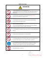
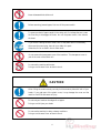
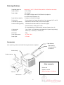
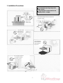
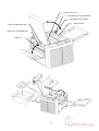
MBM BC12 Multi
Card Cutter
Instruction Manual
Provided By
http://www.MyBinding.com
http://www.MyBindingBlog.com
BC-12
MULTI CARD CUTTER
Operation Manual
*Be sure to read this manual to operate the machine safty and properly.
*Keep the manual in handy place for further reference.
*Be sure to include this manual with the machine when transferring or
leasing it to another person.
*The manual is supposed to be changed or renewed without prior notice.
BC-12
MULTI CARD CUTTER
Operation Manual
V.1.0
October 2009
BC-12 Operation Manual
Contents
Introduction ······················································································································ 2
Explanation of Symbols ································································································ 2
Safety Instructions ······································································································· 3-5
Main Specifications ······································································································· 6
Accessories ···················································································································· 6
1. Installation Precautions ··························································································· 7-8
2. Part Names ············································································································· 9-10
3. Composition and Imposition ·············································································· 11-16
4. Preparations for Operation ·················································································· 17-18
5. How to Use ·········································································································· 19-30
6. Handling of the Trash Box ····················································································· 31
7. Power Off ················································································································· 31
8. Maintenance ········································································································· 32-33
9.Option ······················································································································· 34
10. Troubleshooting Q&A ······················································································ 35-36
1
Introduction
Thank you for purchasing BC-12.
BC-12 is an automatic cutter that accurately cuts letter-size paper to produce various sizes
of individual cards such as business cards imposed and printed in advance.
This operation manual describes how to obtain the best performance from the machine
and to use it safely without troubles.
Be sure to read this manual before installation and operation, then keep the manual
carefully in a handy place for further reference.
When transferring or leasing this machine to another person, be sure to include this
manual with it.
Explanation of Symbols
The following safety symbols are used in this operation manual and on the labels attached to the
machine body. Understand each symbol and its associated instruction.
Misuse of the machine could cause major injury or death to the
operator.
WARNING
CAUTION
Misuse of the machine could cause injury to the operator or damage to
property.
Prohibited
Do not expose to
wet conditions
Do not
Do not touch
disassemble
with wet hands
Unplug
Must be grounded
General instruction
2
Safety Instructions
WARNING
Connect the power plug into an outlet rated at 120V.
It is prohibited to connect it to an outlet with many other plugs connected or to
an auxiliary power outlet. Doing so may generate heat and cause fire or an
electric shock.
It is prohibited to use power other than the designated one (AC120V).
Doing so could cause fire or an electric shock.
It is prohibited to connect or disconnect the power plug with wet hands.
Doing so could cause an electric shock.
Handle the power plug carefully.
1. Do not connect the power plug if foreign matter such as dust is attached.
2. Make sure the plug is properly inserted into the outlet.
It is prohibited to use power cords other than the one provided with the
machine.
Do not use the provided power cord for other purposes.
Do not damage the power cord. Doing so could cause fire or an electric shock.
Do not put heavy objects on it, pull it, bend it forcibly, or modify it.
Do not operate the machine without grounding. Doing so could cause fire or an
electric shock. Be sure to ground the machine. If the outlet is not triplex
(three-pins), be sure to ground it securely using the ground adapter.
Never disassemble the cutter unit.
3
Never disassemble the slitter unit.
Before removing jammed paper, first turn off the power switch.
To remove a sheet of paper caught in the cutter unit, first release the error, press
the Start Key to disengage the cutter, turn off the power switch, then remove
the sheet.
If you notice a strange sound or smell, turn off the power switch immediately,
disconnect the power plug, then call your dealer for repair.
Otherwise, fire or an electric shock could result.
Do not remove the transparent cover of the trash box. This transparent cover is
part of the cover of the slitter unit.
Do not wet the machine with water.
Doing so could cause fire or an electric shock.
CAUTION
When lifting the machine body, securely hold the bottom plate with both of your
hands. If you grab part of the plastic cover, it may damage the cover and the
machine could fall and cause an injury.
Do not rub your hands on the edges of cut paper.
Doing so could injure your hands.
Do not use the machine in dusty or damp conditions.
Doing so could cause fire or an electric shock.
4
Do not place the machine on an unstable place.
It may fall down, resulting in an injury.
Remove the power plug from the outlet when the machine will not be used for a
long time.
When disconnecting the power plug, hold the plug and pull it out. Do not pull
on the cord.
Regularly disconnect the power plug from the outlet and clean the area around
the pins. If the plug is kept connected for a long time, the area around the pins
may become dusty, which could cause a short-circuit and result in fire.
When moving the machine, first turn off the power switch and disconnect the
power plug from the outlet.
When installing or removing an optional device, carefully follow the
instructions in the relevant operation manual.
5
Main Specifications
Supported paper size
letter-size 11”×8.5” (279.4 215.9mm, within ±0.5mm from each side)
Paper thickness
0.13–0.35mm
Paper weight
120–350g/m2
For range 321-350g/m2 and 0.31-0.35mm thick, subject to
no-continuous and light-duty use.
Paper feed tray capacity
50 sheets (for 0.2mm-thick paper)
Finished size
For the dimensions of paper that can be cut into, see pages 14, 15 and 16.
Card receiving capacity
500 sheets for business cards (for 0.2mm-thick paper)
Product receiving capacity
120 sheets for business cards (for 0.2mm-thick paper)
(50–100 sheets for other types of card)
(It varies depending on the dimensions and type of paper to be cut)
Cutting speed
1 min. 18 sec. for 100 business cards (based on 10-up and single cutting)
Dimensions
750mm (W)
Net weight
24kg
Power requirements
AC120V, 60Hz
Power input
0.7A max.
435mm (D)
290mm (H)
Accessories
Paper feed tray
After unpacking, make sure that the following accessories are present.
Paper feed tray
fixing thumbscrew
(2 locations)
Machine body
Product receiver
Other accessories
• Power cord
• Operation manual
• Slitter Cartridge v.s. Cut Mode
Trash box
Card receiver
6
1. Installation Precautions
Recommended operating temperature
range: 10–40°C
It is preferable to use the machine at a
humidity of 50% or higher.
Avoid areas with high moisture, excessive dust,
oily smoke or steam.
Do not put the
machine on an
unstable surface.
Keep the machine
away from fire or
heating equipment.
Do not leave the
machine exposed to
direct sunlight for
many hours.
Do not drop the machine or
hit it against something.
7
No wet hands
Danger of an
electric shock
Earth (ground)
Earth terminal
Do not spill cold or
hot water on the
machine.
Do not place any
object on top of the
machine.
Connecting many
leads into a single
outlet is dangerous.
Do not use the machine
with any current and voltage
other than 120 VAC.
Do not place the machine in
extremely hot or cold areas.
When carrying the machine,
be sure to place both of your
hands underneath to hold it.
8
2. Part Names
Top panel
Operation panel
Slitter check panel
Paper feed tray
Power inlet
Power switch
Rear cover
Slitter cover
Product receiver
Trash box
Front cover
Card receiver
9
Pressure roller unit
Paper feed unit fixing thumbscrew
Paper feed unit fixing plate
Paper feed unit
Slitter unit adjustment dial
Slitter unit fixing thumbscrew
Slitter unit
10
3. Composition and Imposition
Composition: To design a form for the end product by combining characters, illustrations, images, etc.
Imposition: To lay out the required quantity of designed forms in a predetermined position on
letter-size paper.
Example of business cards in
a ten-up format imposed on
letter-size paper
Composition means designing a form
within this frame as the end product.
3.1 The size of paper designated for this machine is letter-size (11” 8.5”mm).
Test the friction coefficient and color (transparency/depth) of paper before use.
3.2 This machine cuts letter-size paper based on various cutting dimensions according to the Prescribed Imposition
Format Table (pages 14, 15 and 16).
Therefore, it is necessary to impose a designed form on the paper based on the dimensions of the product to
be cut.
Cutting mode is a program that cuts letter-size paper along the long side of the paper. This machine provides
10 types of cutting mode.
By combining this cutting mode and the slitter unit (for cutting along the short side of the paper), paper can be
cut into various dimensions.
The machine comes with BC and FD slitter unit at the time of purchase.
For details of the combination of cutting mode and slitter unit available for imposition of forms to be
cut, see the Slitter Cartridge v.s. Cut Mode (page 13).
11
3.3 Method of composition and imposition
The composition should be prepared based on your own design.
Imposition should be made based on the position and dimensions specified in the Prescribed Imposition
Format Table that can be processed by this machine (the table is given on pages 14, 15 and 16).
For imposition work, Illustrator is recommended for precisely laying out the dimensions and positions.
Use of templates
You may use templates for prescribed imposition (prepared by Illustrator), which can be downloaded
from the relevant software website.
You should lay out forms within the frame of the template.
For details, download and read the explanation of how to use templates.
Adobe Illustrator is a registered trademark of Adobe Systems Incorporated in the United States.
3.4 After completing composition and imposition, output the required quantity of products using a printer.
3.5 The top and bottom, and right and left margins may not be printed precisely according to the imposition. If this
happens, fine adjustments can be made using the Adjust Top Margin Key on the operation panel for the
vertical direction (along the long side of paper) and the slitter unit adjustment dial for the horizontal direction
(along the short side of paper). (For details, see page 24.)
3.6 If the paper is curled (bent, wavy, etc.), correct it by hand to make the paper as even as possible before
printing.
Feeding curled or folded paper may cause a paper jam.
12
Cutting Mode/Slitter Combination Table
ご確認願い
ます
13
BC-12 Prescribed Imposition Format Table (1/3)
Cutting Mode 1 (Lettet)
Cutting Mode 2 (Lettet)
Cutting Mode 3 (Lettet)
14
VersaTrim Prescribed Imposition Format Table (2/3)
Cutting Mode 4
(Lettet)
Cutting Mode 6 (Lettet)
Cutting Mode 5 (Lettet)
Cutting Mode 7 (Lettet)
Cutting Mode 9 (Lettet)
15
Cutting Mode 8 (Lettet)
VersaTrim Prescribed Imposition Format Table (3/3)
Cutting Mode 10 (Legal)
16
4. Preparations for Operation
4.1 Use this machine under the operating environment specified in “1. Installation Precautions”.
4.2 Attach the necessary accessories to the machine body.
4.2.1 Installing the paper feed tray
Paper feed tray
[2] Securely fix it using
the provided thumbscrews (2
locations).
[1] Insert the paper feed tray into the
back along this guide.
4.2.2 Installing the product receiver
Securely install it
between these
projections.
Product receiver
Trash box
4.2.3 Installing the trash box
Make sure that the trash box is securely inserted into the back.
17
4.3 If the outlet is not triplex (three-pins) (with ground wire), be sure to attach the provided adapter to the power
plug and ground it.
WARNING
When lifting the machine body, securely hold the bottom plate with both of your hands. If you grab
part of the plastic cover, it may damage the cover and the machine could fall and cause an injury.
4.4 Insert the power cord plug into an AC120V outlet.
CAUTION
Do not connect or disconnect the power cord plug to and from the outlet with wet hands. Doing so
could cause an electric shock.
CAUTION
When disconnecting the power plug, hold the plug and pull it out. Do not pull on the cord.
4.5 Load the letter-size paper to be cut into the paper feed tray.
Push down the front guide of the paper feed tray.
Place the paper face up, jog the sheets well,
Push down the front guide.
and insert the paper leftward to the far end.
Release the front guide to complete the setting.
Up to 50 sheets (for 0.2mm-thick paper) can be loaded.
WARNING
Do not rub your hands on the edges of cut paper. Doing so could injure your hands.
4.6 Turn on the power switch.
The display panel in the center of the operation panel lights up.
18
Load the paper.
5. How to Use
5.1 Operation panel
Operation panel
Display panel
• Display panel
The setting of the number of products to be cut, number of cut cards, etc. are displayed.
If the top margin is adjusted, the dimension of the margin width is displayed.
Whether the number of products or adjusted dimension of the top margin is displayed can be identified
by the pilot lamps on the right.
If an error occurs, its error code is displayed.
• Start Key
Press this key to start cutting. While the machine is in operation, the pilot LED lamp (green) above the
key is lit.
• Stop Key
If this key is pressed while cutting is in progress, the operation stops after cutting the paper being
processed, then finishes. While the machine is not in operation, the pilot LED lamp (red) above the key
is lit.
・Ready/Clear Key
When an error occurs, press this key to release the error. (Nothing happens while the machine is in
normal condition.)
• Cutting Mode Select Key
Press this key to select one of the 12 cutting modes. If the key is kept pressed (0.5 seconds), the pilot
LED lamp of each cutting mode lights up in turn.
• Cutting Mark Key
Press this key to switch on or off the cutting mark function. While the cutting mode function is switched
on, the pilot LED lamp (red) above the key is lit. (While it is switched off, it is not lit.)
• Reset Key
Keep pressing this key to reset the number of products displayed.
• Mode Key
Press this key to switch the counter mode between adding mode and preset mode.
• Adjust Top Margin Key
Press this key to adjust the top margin.
•▲Key and ▼Key
When the number of products is input in preset mode, this key is used to increase or decrease the number.
When the top margin is adjusted, the key is used to adjust it in increments of 0.1mm.
19
5.2 Checking no error is displayed on the display panel
If the machine is in the normal condition, the Ready/Clear LED lamp lights up and the display panel
shows “0000” or the number of products processed last time.
(The number of products means the number of cards cut and ejected onto the product receiver.)
5.3 Removing errors
If an error is displayed, press the Ready/Clear Key to release the error.
If the error is not released even after pressing the key, it is necessary to solve the error depending on its
content.
Error Code
Cause of error
Remedy
E002
Malfunction of the cutter unit
E003
The slitter unit is not properly installed.
Properly install the slitter unit.
E006
S2 sensor cannot detect the paper edge.
Lift the paper feed unit, remove the paper, and
Press the Ready/Clear Key to release the error.
reset the paper properly.
E007
E008
Paper delivery failure
(Paper does not reach S3 sensor within the
predetermined time limit.)
Paper delivery failure
(Paper does not pass through S3 sensor within
the prescribed time limit.)
Remove the sheet or scrap of paper jammed or
remaining in the machine.
Remove the sheet or scrap of paper jammed or
remaining in the machine.
E002, E006, E007 and E008 are errors that occur when there may be a paper jam, or a scrap of
cut paper, or a piece of torn paper remaining in the machine. For details on how to handle
these, see “5.13 Removing a paper jam” (page 26).
5.4 Selecting the cutting mode
When the power switch is on, the cutting mode used last time is selected.
If the cutting mode need not be changed, leave it as it is.
If the Select Key is kept pressed, the green pilot LED lamp of each cutting mode from 1 to 10 lights in
order. Release the Select Key when the LED lamp of the desired cutting mode lights up.
(Each LED lamp is lit for 0.5 seconds.)
If the LED lamp of the desired cutting mode goes off before selection, restart and keep the key pressed
to select the right one.
(The pilot lamps cannot be made to light up in reverse direction.)
20
5.5 Selecting the cutting mark function
Each time the Cutting Mark Key is pressed, the red pilot LED lamp light up or goes off.
If you do not use the cutting mark function, turn the LED lamp off.
If you use the cutting mark function, turn the LED lamp on.
If you do not use the cutting mark function, the machine cuts away the top margin at the distance of the
imposed dimension from the edge.
If you use the cutting mark function, the machine cuts away the top margin at the distance of 3mm
from the edge of the printed cutting mark regardless of the dimension of the top margin.
The cutting mark is printed together with the composed content, so that even if printing is out of
position, the paper can be cut with almost no shear from the designed layout in the direction of the
long side of letter-size paper because cutting is performed based on the cutting mark.
If you compose and print the cutting mark simultaneously, print it in the following position.
Top margin
Direction of paper feed
Cutting mark (solid black)
The cutting mark can be used when the cutting mode is 1, 2, 3, 5, 9, or 10. If the cutting mode is 4, 6, 7,
or 8, no top margin remains so this function cannot be used.
The cutting mark is printed in black, but depending on the type of ink used for the printer, the cutting
mark may not be detected by the sensor of this machine. Also, the cutting mark may not be detected
depending on the color of the paper (particularly deep colors).
If the cutting mark function is used but no cutting mark is printed on the paper, the machine stops and
E006 is displayed on the display panel.
(Also, in cutting mode 4, 6, 7, or 8, there is no top margin, and so the machine stops in the same way.)
If the cutting mark function is not used but a cutting mark is printed on the paper, the paper is cut
based on the top margin width set by the selected cutting mode.
Because the cutting mark is placed in the margin of the paper, some printers may not be able to print it.
21
5.6 Selecting the counter mode
If the adding mode is selected using the Mode Key, the adding LED lamp lights up and the cumulative
number of cut products is displayed on the display panel.
If the machine is operated in adding mode, the machine continues operating until the Stop Key is
pressed, or until there is no more paper in the paper feed tray.
If the preset mode is selected, the preset LED lamp lights up, and by pressing the ▲ or ▼ Key, the
preset number (number of products) can be increased or decreased. The set number of products will
then be cut.
If the machine is operated in preset mode, when the preset number displayed on the display panel
becomes “0000”, the machine stops and stands by, and the preset number will be displayed again.
If the machine is operating based on the preset number, when it runs out of paper in the paper feed tray,
the machine stops and the remaining number of products to be cut will be displayed. If additional
paper is loaded on the tray and the Start Key is pressed, the machine will restart and cut the remaining
number of sheets.
The minimum number of sheets that can be preset varies depending on the selected cutting mode and
the slitter unit. Thus, the number of products imposed on letter-size paper becomes the minimum unit,
and multiples of this unit can be preset.
5.7 Adjusting the top margin (if necessary)
If there is a misalignment in the first cutting position, such as shear in printing, in the direction of the
long side of letter-size paper, this can be used for adjustment. (Adjustable range: ±1mm)
First, select the cutting mode under which the top margin width is adjusted. (Keep pressing the Select
Key.)
If the Adjust Top Margin Key is pressed, the pilot LED lamp on the right of the display panel is
switched, the Adjust Top Margin LED lamp lights up, and the present set value of the top margin will
be displayed.
By pressing the ▲ or ▼ key, adjustments can be made in increments of 0.1mm (Adjustable range:
±1mm).
When the adjustment is finished and the Adjust Top Margin Key is pressed, the set value is stored and
the display panel shows the number of products again.
The initial values of the top margin width are set as follows for each cutting mode.
Initially set values of top margin
Cutting mode 1:
0.5”
Cutting mode
6: 0”
Cutting mode 2:
0.25”
Cutting mode
7: 0”
Cutting mode 3:
0.5”
Cutting mode 8:
0.0”
Cutting mode 4:
0.0”
Cutting mode 9:
0.25”
Cutting mode 5:
0.5”
Cutting mode 10:
0.33”
In cutting mode 4, 6, 7 or 8, no top margin is left. Therefore, if the top margin is adjusted, the cutting
dimensions of the first sheet are adjusted.
22
5.8 Starting operation
Press the Start Key to start operation.
The Start LED lamp (green) is lit while the machine is in operation, and the Stop LED lamp (red) is lit
when operation has stopped.
So far, this manual has explained various setting methods, including how to release errors, select the
cutting mark function, select the counter mode function, and adjust the top margin. However, if these
settings or adjustment are not necessary, basic operations can be performed as follows.
[1] Load the paper in the paper feed tray.
↓
[2] Select the cutting mode.
↓
[3] Specify the number of products to be cut (only when the preset mode is set).
↓
[4] Press the Start Key to start operation.
5.9 Stopping operation
If the Stop Key is pressed while the machine is in operation, the Stop LED lamp (red) lights, and after
the cutting process in progress has finished, the machine stops operation.
If the Start Key is pressed after the operation is stopped, the machine starts operation again.
(Do not press the Start Key or Stop Key before the operation stops.)
5.10 Emergency stop and safety device (Interlock)
If [1] the top panel or slitter cover is opened, or [2] the trash box is pulled out, during operation, the
machine stops immediately. If an emergency stop is necessary, use either of these methods.
To start operation again after [1] closing the top panel or slitter cover, or [2] installing the trash box,
and after removing any sheet or scrap of paper remaining in the machine, press the Ready/Clear Key
to put the machine in the stand-by state.
While the top panel,the slitter cover is open or the trash box is not set to its proper position,the machine
power can not be turned on and the display go out because of safty feature.
Because this function is part of the machine’s safety feature, the machine does not work until the top
panel, slitter cover and trash box are returned to their proper positions.
23
5.11 Adjusting the right and left side margins (direction of the short side of letter-size paper)
The right and left side margins (direction of the short side) are adjusted by moving the slitter unit. Be
sure to turn off the power before making this adjustment.
Open the slitter cover and slightly loosen the slitter unit fixing thumbscrew.
Turn the slitter unit adjustment dial to adjust the position of the slitter unit (within ±2mm).
The scale is useful as a guide for adjustment.
When the slitter unit adjustment dial is turned to the right, the slitter unit moves forward, and when
turned to the left, the unit moves backward.
Slitter unit adjustment dial
Scale
Slitter unit
fixing thumbscrew
Slitter unit
Slitter cover
After completing the adjustment, securely tighten the slitter unit fixing thumbscrew.
5. 12 Removing the slitter unit (Replacement)
If you remove or replace the slitter unit, be sure to turn off the power switch.
Open the slitter cover and remove the slitter unit fixing screw.
Lean the handle portion of the slitter unit by pushing it down to remove the slitter unit.
You can install the slitter unit in the reverse process, but it is necessary to securely insert the groove
portion of the slitter unit into the slitter unit fitting reference shaft mounted in the machine body.
(Securely insert it so that there is no space between the groove and the shaft.)
When the unit is installed, securely tighten the slitter unit fixing thumbscrew.
*The noise come out while running machine just after installing or replacing the slitter unit.
This is because the gears of between the machine body and the slitter units may not be fitted
appropriately.
In that case please reset the slitter unit.
24
Slitter unit fixing thumbscrew
Slitter cover
Slitter unit
Handle portion
Slitter unit fitting reference shaft
Groove portion
25
5.13 Removing a paper jam
WARNING
Before trying to remove a sheet or scrap of paper jammed inside the machine, first turn off the power
switch. Otherwise your hand may be caught in the machine or you could receive an electric shock.
To make it easier to remove a sheet or scrap of paper jammed inside the machine, each unit can be removed or
opened as shown below.
Slitter unit
Top panel
Pressure roller unit
Paper feed unit
Slitter cover
Trash box
The main remedy for handling paper jams are explained later in this manual. Deal with it according to the
location and type of error.
26
5.13.1 When “E002” is displayed
“E002” indicates the cutter unit may have stopped during cutting operation.
Turn off the power switch, open the top panel, and then open the paper feed unit by loosening the
paper feed unit fixing bracket and lifting the unit.
The cutter unit is installed behind the first delivery roller under the paper feed unit. Check whether it
has stopped cutting paper halfway.
If it has stopped cutting paper halfway, close the paper feed unit and top panel, turn on the power
switch, and press the Ready/Clear Key. Then, the cutter in the cutter unit will then be disengaged.
(The sound of the cutter being released is heard for a moment.)
After turning off the power switch, open the top panel and paper feed unit and remove any paper or
scrap of paper remaining near the cutter unit.
To remove a scrap of paper remaining near the cutter unit, push in an A4 sheet as shown in the drawing
on the next page, then you can easily make the scrap drop into the trash box.
Also, to pull out a sheet of paper stuck in the first delivery roller, gently drop the paper feed unit
further as shown in the drawing. The roller will move up and you can pull out the paper.
After completely removing the remaining sheet or scrap of paper, securely close the top panel and
paper feed unit, turn on the power switch, and press the Ready/Clear Key.
(When closing the paper feed unit, securely tighten the thumbscrew of the paper feed unit fixing
bracket.)
WARNING
When removing a sheet of paper caught in the cutter unit, be sure to turn off the power
switch before doing so. Otherwise, it may injure your fingers, or cause an electric
shock.
27
Thumbscrew
Bracket for fixing paper feed unit
Top panel
Paper feed unit
State before the paper feed unit is
opened
First delivery roller
S2 sensor
The cutter unit is behind
here.
Never put your finger inside
this.
Gently drop the paper
feed unit down further,
and the first delivery
roller will move up a
little.
Push in an letter-size sheet
to make the scrap of paper
remaining in the back drop
into the trash box.
Letter-size paper
28
5.13.2 When “E006” is displayed
“E006” indicates that a sheet of paper was drawn into the machine but it was stopped because the
sensor that detects the edge of paper (S2 sensor) cannot detect the edge properly.
“E006” also occurs when a piece of paper such as a margin that was cut during cutting operation does
not fall into the trash box but remains near the sensor (S2 sensor).
Turn off the power switch, open the top panel and paper feed unit, and remove the remaining sheet or
scrap of paper.
Securely close the top panel and paper feed unit and turn on the power switch.
(When closing the paper feed unit, securely tighten the thumbscrew of the paper feed unit fixing
bracket.)
If “E006” is still displayed, press the Ready/Clear Key.
5.13.3 When “E007” is displayed
“E007” occurs when paper does not reach the S3 sensor within the time frame set by the operation
program of this machine. In other words, the paper is stopped (or stuck) somewhere between the S2
sensor and S3 sensor.
Turn off the power switch, open the top panel and pull out the pressure roller unit upward.
Remove the sheet or scrap of paper remaining in the machine.
Install the pressure roller unit in the proper position, close the top panel, then turn on the power switch.
If “E007” is still displayed, press the Ready/Clear Key.
If this error cannot be released by this procedure, other paper may be remaining under the paper feed
unit. Check this part, too. (See 5.13.2.)
5.13.4 When “E008” is displayed
“E008” occurs when the paper has not passed through the S3 sensor within the time frame set by the
operation program of the machine. In other words, the paper is stopped (or stuck) somewhere at or
after the S3 sensor and before ejection.
Turn off the power switch, open the top panel and pull out the pressure roller unit upward.
Remove the sheet or scrap of paper remaining in the machine.
If paper is remaining not only in the pressure roller unit but also in the slitter unit, open the slitter cover
and remove the paper from the ejection outlet side of the slitter unit.
When removing the jammed paper from the ejection outlet side of the slitter unit, pick it up and pull it
out using tweezers, etc.
(Never put your fingers inside the ejection outlet, as the slitter blade inside could cause an injury.)
29
Install the pressure roller in the proper position, close the top panel and slitter cover, and turn on the
power.
If “E007” is still displayed, press the Ready/Clear Key.
If the paper cannot be properly removed from the ejection outlet side of the slitter unit, remove the
slitter unit from the machine body, and while turning the gear of the slitter unit, grasp the jammed
paper using tweezers, etc. and pull it out. Take care not to trap your fingers in the gear which could
cause an injury.
Pressure roller unit
S3 sensor
Gear
Slitter unit
Do not put your fingers in here, as
there is a blade inside.
Use tweezers, etc. to remove the
remaining paper.
30
6. Handling the Trash Box
While cutting is in progress, cut strips are collected in the trash box.
When the box becomes too full with margins, some may gather around the cutter and could cause a
paper jam. Frequently empty the strips from the trash box (after cutting approximately 50 sheets of
letter-size paper).
WARNING
When the trash box is pulled out, do not put your hand inside the machine from under
the slitter unit. When the trash box is pulled out, the safety device works and the
machine stops, but the blade in the back could injure your fingers.
WARNING
Do not remove the transparent cover of the trash box, as it is part of the cover of the
slitter unit.
7. Power Off
When cutting work is finished, turn off the power switch.
If the machine will not be used for many hours, remove the power plug from the outlet.
WARNING
If you notice a strange sound or smell while the machine is operating, turn off the
power switch immediately, remove the power cord plug, and contact your dealer for
inquiries/repairs.
31
8. Maintenance
WARNING
Turn off the power switch before performing maintenance work, otherwise your hand may be caught
in the machine or you could receive an electric shock.
8.1 Maintenance check and replacing the pick-up roller
If the pick-up roller in the paper feed unit becomes worn out and paper feed failure occurs, replace the
pick-up roller. (For replacing the pick-up roller, contact your dealer.)
Remove the roller fitting thumbscrew and replace the roller with a new one.
Note that the pick-up roller has a fixed direction.
(There is a clutch with a unidirectional rotation, so if the roller is placed in the reverse direction, it will
not rotate in the proper direction.)
Pick-up roller
The side where the screw
is tightened contains the
clutch with unidirectional
rotation.
8.2 Maintenance check and replacing the separation pad
If the separation pad under the paper feed unit becomes worn out and paper feed failure occurs, replace
the separation pad. (For replacing the separation pad, contact your dealer.)
The separation pad is attached with double-sided adhesive tape. Attach the new one after completely
removing the remaining adhesive and dust.
Separation pad
32
8.3 Replacing the blade
When cut edges are no longer crisp, it is time to replace the blade.
If the short side of letter-size paper (vertical direction when seen from the front of the machine) is not
cut well, the cutter unit needs to be replaced.
If the long side of letter-size paper (horizontal direction when seen from the front of the machine) is
not cut well, the slitter unit needs to be replaced.
In either case, contact your dealer to place an order to a special agent or maker.
WARNING
If you touch the blade inside the cutter unit or slitter unit, you could be seriously
injured. Never disassemble the cutter unit or slitter unit.
The blades of the cutter unit and slitter unit built into the machine are highly durable and developed
for cutting general paper. If they are used to cut any paper other than the specified one, the blades
may become nicked and their durability severely deteriorated. Take great care to ensure that no clips
or staples enter the device together with paper.
8.4 Prohibition of disassembly
Do not disassemble any parts other than those specified for maintenance in this operation manual.
This machine was shipped after being optimally adjusted. Inadvertent disassembly could degrade
machine performance or cause failure, and could also cause an injury.
8.5 Others
This machine needs no lubrication.
Do not wipe the coated external cover, particularly plastic parts, using alcohol or solvent.
Doing so may damage the plastic surface or coating.
33
9.Option
9.1
Slitter Unit
*The machine comes with BC and FD slitter unit at the time of purchase.
(Either B90 or B85 can be selected at the time of purchase.)
You can purchase below optional slitter unit suitable for the cutting forms.
Slitter BC
Business Card(3.5”)
(Standard)
Slitter FD
Full Width for Division
(Standard)
Slitter SC
Scoring (Center)
(Option)
Slitter PE
Perforation (2.16” Right)
(Option)
Slitter PH
Photo 2L (5.0”×7.0”)
(Option)
Slitter PC
Post Card (4.0”×6.0”)
(Option)
*Refer to Cutting Mode/Slitter Combination Table on page 13 and BC-12 Prescribed Imposition
Format Table on page 14, 15 and 16 as to the detail for the cutting forms.
34
10. Troubleshooting Q&A
If you think the machine is out of order, check the following first.
Q1 The display panel and all pilot LED lamps do not light up when you turn on the power switch.
Is the power cord properly connected?
Is the outlet live with electricity?
○ If the LED lamps do not light up after you have checked the above, the machine is out of order.
Q2 The machine does not work when you press the Start Key.
Is an error displayed on the display panel?
Is the Ready/Clear LED lamp (green) lit?
(Did you forget to release the error by the Ready/Clear Key?)
Is 0 (zero) displayed as the number of products set under the preset mode of the counter?
○ If the machine does not start even after checking all of the above, the machine may be out of order.
Q3 The machine does not start feeding the paper when you press the Start Key.
Is the paper too thick? (Paper must be no thicker than 0.35mm and no heavier than 350g/mm2.)
Are the edges or corners of the paper heavily curled?
Is the paper stained with oil or powdery substance?
Is the friction on the paper surface too strong or weak?
Is the pick-up roller or separation pad worn out?
→ In this case, see “8. Maintenance.”
○ If it does not feed paper even after checking and correcting all of the above, the machine may be out of
order.
Q4 Paper stops moving ahead after moving slightly.
Are you using nonstandard paper (highly transparent paper, dark color paper, paper that reflects light
diffusely)? (The sensor cannot detect the edge.)
○ Use suitable paper.
Q5 The machine has started to feed two sheets or more, even though normal paper is used.
If the sheets stick together because of static electricity:
→ Fan the stack of sheets and reload them.
Atmospheric humidity is too low → Increase humidity (using a humidifier, etc.).
Is the machine properly grounded? → Ground the machine securely.
Is the separation pad worn out? → In this case, see “8. Maintenance.”
○ If these procedures do not solve the problem, the machine may be out of order.
35
Q6 The blade does not cut partly.
There may be nicks in the blade. If so, it is necessary to replace or repair the cutter unit or slitter unit.
Contact your dealer.
Q7 The cut edges are not crisp.
The blade needs to be replaced. It is necessary to replace or repair the cutter unit or slitter unit. Contact
your dealer.
Q8 The lengths of finished cards are unequal (by more than ±0.15mm)
The paper may be too curly or wavy to allow smooth delivery of paper.
→ Remove the curls or waves as far as possible.
The paper may have too much friction to allow smooth delivery.
→ Try a different kind of paper.
○If these procedures do not solve the problem, contact your dealer.
Q9 Cutting accuracy is good, but the positions of printed images are uneven.
The composition or imposition may be incorrect.
→
Make sure that they are based on the predetermined dimensions and positions.
The output printing may be sheared.
→
Correct the positions of printed images.
Q10 The display panel of the operation panel does not display as operated.
○ It is out of order.
Q11 When the cutting mode is set to “Double Cut,” cut margins go forward instead of falling into the trash box,
causing problems.
Static electricity may make thin cut margins stick to the blade or nearby parts, and thus not fall into the
trash box.
→
Use the machine in an atmosphere with at least 50% humidity (using a humidifier, etc.).
Q12 The machine shows abnormal operation.
Turn off the power switch, wait for more than seven seconds, then turn on the power.
○ If the situation remains the same, the machine may be out of order.
36