1
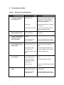
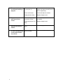
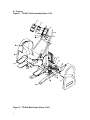
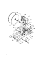
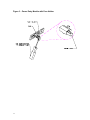
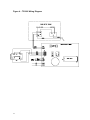
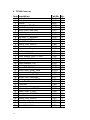
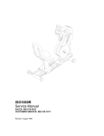
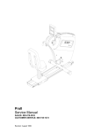
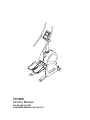
TC1000
Service Manual
SALES: 800-278-3933
CUSTOMER SERVICE: 800-745-1373
Table of Contents
Section
Page
I.
Overview
2
II.
Troubleshooting Tables
3
III.
Maintenance Procedures
IV.
V.
1
Procedure 1 – Removal and Reinstallation of
the Power Supply Board
6
Procedure 2 – Checking Voltage at the
Power Supply Board
6
Procedure 3 – Checking and Adjusting the
Speed Sensor
7
Procedure 4 – Removal and Replacement of
the Brake Assembly
7
Figures
Figure 1 – TC1000 Total Assembly (Items 1-20)
9
Figure 2 – TC1000 Main Frame (Items 21-43)
10
Figure 3 – Power Entry Module with
Fuse Holder
11
Figure 4 – TC1000 Wiring Diagram
12
TC1000 Parts List
13
I. Overview
Purpose.
This manual is designed to assist in service of SCIFIT TC1000 exercise
machines. The manual is divided into sections to diagnose and isolate problems.
Troubleshooting tables and procedures, along with drawings, are provided to aid
technicians in servicing equipment. The Item Numbers given in the parts list in
Section V can be used to determine the location of various parts in Figures 1
and 2.
When troubleshooting, the actions taken to resolve problems should be
performed in the order stated. Deviating from this sequence may cause damage
to the equipment and lead to unnecessary repairs.
Technical Support.
For further assistance in service of SCIFIT products, please call (800)
745-1373, extension 21. The technical support department is staffed from 8 AM
to 5 PM CST Monday through Friday. A voicemail service is available 24 hours
daily for recording messages to request technical support and to order
replacement parts.
Please have the following information prior to calling technical support:
•
•
•
•
2
Model number of equipment
Serial number of equipment
Point of contact name and phone number
Detailed description of symptoms encountered.
II. Troubleshooting Tables
Table 1 – Electrical Troubleshooting
Problem
1.1 The machine appears to
be off when plugged in
and switched “on”.
Possible Reasons
Faulty power supply
board (Item 23).
Solutions
If buttons on the control display
beep when pressed, replace power
supply board. See Procedure 1.
Otherwise, check power supply
board. See Procedure 2.
Faulty fuse.
Check and replace fuse if needed.
(See Fig. 3)
Loose cable connection.
Check wire connections at power
supply and display boards.
1.2 Upper control panel
(Item 2) lights are dim.
Power supply board
(Item 23) is faulty.
Replace power supply board. See
Procedure 1.
1.3 Upper board (Item 2)
accepts commands but
rotational resistance
does not change.
Dip switch setting is
incorrect.
Set dip switch to 01.
Power supply board
(Item 23) is faulty.
Check and replace power supply
board as needed. See Procedure 2.
1.4 LED’s on upper board
(Item 2) blinking off/on,
then go dead.
Ribbon cable (Item 5)
connections are loose.
Check and replace accordingly.
Unplug and re-plug machine to
reset.
Faulty power supply
board (Item 23).
Check and replace power supply
board as needed. See Procedure 2.
Display board (Item 2) is
faulty.
Replace display board.
Chest strap and transmitter improperly worn.
Verify that they are being properly
worn.
Loose sensor lead
connection at display
board (Item 2).
Check and adjust as needed.
Faulty receiver.
If there is no audible signal, replace
receiver.
Too many units are
daisy-chained together.
Do not daisy chain more than 3
units together.
Faulty power supply
board (Item 23).
Check and replace power supply
board as needed. See Procedure 2.
1.5 Heart rate displays zero
(0) in window
1.6 Unit keeps blowing
fuses.
3
Ribbon cable connection
is loose (Item 5).
Check cable connection at power
supply and display boards (Items 23
and 2, respectively).
Power cord is loose.
Check and adjust as needed.
Display board is faulty.
Replace display board.
Ribbon cable (Item 5)
connection is loose.
Check and adjust cable connection
as needed.
Display board (Item 2) is
faulty.
Replace display board.
1.9 Machine shuts down in
programs but works in
manual.
Display board (Item 2) is
faulty.
Replace display board.
1.10
Can’t select program
or enter information and
no beep when buttons
are pressed.
Overlay/switch panel
(Item 1) is faulty.
Replace overlay/switch panel.
1.7 The upper display (Item
2) resets after starting a
program.
1.8 Program stops, lines of
dots shoot across
screen.
4
Table 2 – Mechanical Troubleshooting
Problem
2.1 Pedals lock up while
operating.
2.2 No resistance on pedals
when in a program.
2.3 Very little resistance at
any level.
5
Possible Reasons
Power supply board
(Item 23) is faulty.
Solutions
Unplug power cord. If pedals now
move freely, replace power supply
board.
Brake (Item 30) is faulty.
If pedals do not move with power
cord unplugged, replace brake. See
Procedure 4.
No speed signal
Check and adjust the speed sensor
(Item 37) as needed. See
Procedure 3.
Wires going to brake
(Item 30) are disconnected.
Check that brake wires are properly
connected.
Power supply board
(Item 23) is faulty.
Check and replace power supply
board as needed. See Procedure 2.
Speed sensor (Item 37)
improperly adjusted.
Check and adjust the speed sensor
as needed. See Procedure 3.
Bad speed sensor
connection with power
supply board (Item 23).
Check voltage at power supply
board. See Procedure 2.
III. Maintenance Procedures
Procedure 1 - Removal and
Reinstallation of the Power Supply
Board
1. Unplug the unit from the power
source.
2. Remove the screws (Item 17)
that fasten the covers (Items 10
and 16) to the main frame. The
covers can be removed now.
3. Locate the power supply cover
(Item 22) on unit. Remove the
four (4) screws and the power
supply cover. Be careful when
removing the power supply cover
because of the plastic ties and
brake wires.
4. Cut all the plastic ties.
5. Before disconnecting any of the
wires, make note of the wiring
sequence. Refer to the wiring
diagram, Fig. 4.
6. Disconnect the following:
a. The two (2) white (110 V) and
two (2) black (24 V)
transformer wires. These are
all the wires from J4 on Fig. 4.
b. The black and white wires
from the power entry module
– total of two (2). These are
the wires at terminals ACIN1
and ACIN2 on the LCB.
c. The two (2) red brake wires.
d. The one (1) speed sensor
plug – J5 on Fig. 4.
e. The one (1) ribbon cable.
8. The power supply board (Item
23) can now be removed.
Reinstallation is the reverse of
removal.
9. After reinstalling the power
supply board, perform the
following procedure to test
correct reinstallation.
6
a. Plug into power source and
turn on.
b. The message “SCIFIT FOR
SCIENTIFIC SOLUTIONS”
should be scrolling across
upper display board. If not,
see troubleshooting table.
c. Press the start button.
d. Press SCAN/HOLD so that
the CLIMB RATE indicator
light stays lit.
e. Move the pedals as if
exercising.
f. Verify that the values are
increasing in the CLIMB
RATE window.
g. Press the down arrow key to
slow the pedal speed. It
should be slow and smooth. If
not, consult the troubleshooting table.
h. Press the up arrow key to
increase pedal speed. The
stepping motion should be
fast and smooth. If not, refer
to the troubleshooting table.
Procedure 2 - Checking voltage at
the Power Supply Board
1. Follow steps 1-3 in Procedure 1.
2. Disconnect the speed sensor
from the lower supply board at
the J5 terminal. See Fig. 4. Use a
voltmeter to measure the DC
voltage across the speed sensor
pins on the power supply board.
Measure the voltage across the
pin with the red wire (+) and
either one of the center pins (-).
The voltmeter should measure 45 volts DC.
3. If there is no voltage, replace the
power supply board. See
Procedure 1.
Procedure 3 – Checking and
Adjusting the Speed Sensor
1. Turn machine on and press
START/STOP.
2. Set the LEVEL to 0.0. Stand on
the two pedals until they go down
as far as they will go. The
number in the DISTANCE
window should increase every
time the pedals are pressed
down.
3. If the number in the DISTANCE
window does not increase each
time the pedal is depressed,
proceed to the next step to adjust
the speed sensor.
4. Remove the covers on the
machine (Items 10 and 16).
Locate the speed sensor on the
unit (Item 37).
5. The air gap between the brake
flywheel and speed sensor
should be 1/8”-3/16”.
6. The speed sensor must be
pointed directly at the flywheel so
the eyes of the sensor will
intersect the center of the axis of
the brake. Adjust as needed.
7. Again, stand on the two pedals
until they go down as far as they
will go. If the number in the
DISTANCE window is greater
than zero but does not increase
by one, repeat steps 1-7. If a
reading of zero (0) is displayed,
proceed to step 8.
8. Use a voltmeter to measure the
DC voltage across J5 pin 1 (+)
and J5 pin 2 (-) on the power
7
supply board. Refer to Fig. 4. The
voltmeter should read 4-5 VDC.
9. If there is no voltage, replace the
power supply board (Item 23). If
4-5 volts are present, replace the
speed sensor.
Procedure 4 – Removal and
Replacement of the Brake
Assembly
1. Remove the screws (Item 17)
that fasten the covers (Items 10
and 16) to the main frame. The
covers can be removed now.
2. Tip the entire unit back so that it
is resting horizontally on its two
rectangular shaped feet and the
two pedals. This will allow better
access to the brake from the
underside of the unit.
3. Disconnect the two red wires on
the right side of brake (Item 30).
4. Relieve the tension in the brake
drive belt (Item 42) by loosening
the turnbuckles (Item 29) that are
attached to the brake brackets.
5. Remove the nuts and threaded
bar that hold the brake drive idler
(Item 25) onto the bracket. Also,
loosen the nuts at the lower end
of the brake brackets. With the
idler removed and the brackets
loose, the brake should be loose
enough to remove the belt.
6. Remove the three (3) socket
head screws that hold the brake
assembly to the support bracket.
7. Pull brake away from main frame.
Be careful not to damage the
speed sensor when removing the
brake.
8. Remove the brake from the
machine and set aside to return
to SCIFIT (request a UPS call tag
by phone).
9. Reinstallation is the reverse of
removal. Before tightening the
tension in the brake drive belt,
make sure that it is centered
correctly.
10. After brake assembly has been
aligned and tension set, attach
speed sensor tape to the brake
armature. First peel off tape
backing on the end with the wide
silver band and stick on the brake
surface hanging down. The tape
should be on center with the
speed sensor. Slowly rotate the
brake upward and wrap tape
around the circumference of the
brake. It is extremely important
that the speed sensor be
centered over the tape.
11. Stand unit up in its proper
position. Perform steps 12-16. If
the indicated results are not
attainable, see Procedure 3.
12. Plug in and turn on machine but
don’t press any buttons. The
display will be scrolling the
message, “SCIFIT…”
13. Press the START/STOP button.
14. If the LEVEL light is not lit, press
the SCAN/HOLD button until it
becomes lit. Use the down arrow
key to set the LEVEL to 0.0.
15. Stand on the two pedals
simultaneously so that they move
once through their entire range of
motion. The TOTAL CLIMB
window should display 1. If it
does proceed to step 16;
otherwise, check that the air gap
between the speed sensor and
brake flywheel is 1/8”-3/16” then
repeat steps 14 and 15.
16. Use the UP arrow button to set
the LEVEL to 4.0.
8
17. Stand on the pedals and begin
moving them at a rate typical of a
workout.
18. The resistance on the pedals
should feel smooth and
consistent. If it does, installation
is complete; otherwise, see
Procedure 3.
IV. Figures
Figure 1 – TC1000 Total Assembly (Items 1-20)
Figure 2 – TC1000 Main Frame (Items 21-43)
9
10
Figure 3 – Power Entry Module with Fuse Holder
11
Figure 4 – TC1000 Wiring Diagram
12
V. TC1000 Parts List
Item Description
1
2
3
4
5
6
7
8
9
10
11
12
13
14
15
16
17
18
19
20
21
22
23
24
25
26
27
28
29
30
31
32
33
34
35
36
37
38
13
overlay/switch panel
Display board
Console
Handgrip set, TC1000
cable, ribbon, assy
Pulley, clutch, roller, assy.
Ring, retainer
Arm, pedal, upper
Cap, base, 3", adjustable
Cover, right, TC1000
Bolt, M10x1.5x70
Bearing, roller, 6200-2z
Spacer, arm, upper
Cap, base, rectangular
Pad, foot, rubber
Cover, left, TC1000
Screw, fastener, hood, TC1000
Belt, pedal, TC1000
Bracket, heartrate
Board, heartrate, PCB
Bracket, spring
Cover, PSB, TC1000
Power supply, (lower), serial
Transformer, 24V, 5.4A
Idler, brake drive, TC1000
Recept, PEM, Daisychain
Module, power entry, RF/EFI
Wheel, TC1000
Turnbuckle
Brake, assy.
Roller, belt, pedal, TC1000
Spacer, roller, TC1000
Bearing, roller, 608-2SR
Arm, pedal, lower
Bearing, roller, 6202-2z
Spacer, arm, lower
Sensor, speed, cable, assy.
Shaft, F0.59x10.718
Part No. Qty.
65112
65110
65202
P1368
65120
P1375
P1376
70330
P1362
P1389
P1390
P1377
P1378
P1363
P1369
P1366
A1124
65160
P1379
P1380
65150S
65180
P1381
65177
65178
P1382
P1383
68300
P1393
P1394
P1395
P1384
P1391
P1392
A1089
P1385
1
1
1
1
1
2
2
2
2
1
2
8
4
2
2
1
8
2
1
1
1
1
1
1
1
1
1
2
2
1
2
2
4
2
8
4
1
1
39
40
41
42
43
14
Stopper, rubber
Shaft, drive, main, assy.
Flywheel, TC1000
Belt, drive, brake, TC1000
Spring, return, pedal, TC1000
P1386
P1387
P1388
P1367
P1365
2
1
1
1
2