1
DL-WINDOWS™ for Trilogy Networx™
V4.0 USER'S GUIDE
345 Bayview Avenue
Amityville, New York 11701
For Sales and Repairs 1-800-ALA-LOCK
For Technical Service 1-800-645-9440
Publicly traded on NASDAQ
Symbol: NSSC
© ALARM LOCK 2010
OI352B 11/10
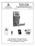
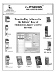
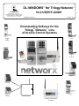
Downloading Software for the
Trilogy® Networx™ Line
of Access Control Systems
PL6500 &
ETPLN
DL6500
&
ETDLN
PDL6500
&
ETPDLN
PL6100
PDL6100
NETPDK
DL6100
NETDK
NETWORXPANEL
Gateway "Wireless/Wired"
AL-IM80211
DL-WINDOWS™ for Trilogy Networx™ V4.0 USER'S GUIDE
1
Table of Contents
Overview ....................................................................................................................................... 3
Minimum Wireless System .......................................................................................................... 3
Network Security .......................................................................................................................... 4
How to Use This Manual .............................................................................................................. 4
Ordering Information ................................................................................................................... 4
DL-Windows System Requirements........................................................................................... 5
Gateway Specifications ............................................................................................................... 6
START HERE ................................................................................................................................ 7
Terminology ................................................................................................................................. 9
Hardware Installation ................................................................................................................. 11
Configuring DL-Windows for Wireless Lock Use ................................................................... 15
Normal Tasks ............................................................................................................................. 22
Replacing Hardware .................................................................................................................. 22
Adding New Hardware ............................................................................................................... 23
Menus ......................................................................................................................................... 26
GW Confg Button ....................................................................................................................... 27
Tools Menu ................................................................................................................................. 29
Actions Menu ............................................................................................................................. 40
Help Menu ................................................................................................................................... 47
Wireless Locks screen .............................................................................................................. 48
Wireless Commands Menu ....................................................................................................... 49
EMERGENCY COMMANDS ....................................................................................................... 49
Right-Click Profile Menu............................................................................................................ 55
Troubleshooting ......................................................................................................................... 62
Radio and Television Interference Statement ......................................................................... 67
Alarm Lock Limited Warranty ................................................................................................... 68
Important: DL-Windows is not a server application and is not designed for server use; the program and its database must be installed and maintained on a local PC, not a server computer. Trilogy® is a
registered trademark of Alarm Lock. ProxCard® and ProxKey® are trademarks of the HID© Corporation.. Microsoft® and Windows® are trademarks of their the Microsoft Corporation. All other
trademarks, service marks, and product or service names described in this manual are for identification purposes only and may be trademarks or registered trademarks of their respective
owners. The absence of a name or logo in this document does not constitute a waiver of any and all intellectual property rights that NAPCO Security Technologies, Inc. has established in any
of its product, feature, or service names or logos.
2
DL-WINDOWS™ for Trilogy Networx™ V4.0 USER'S GUIDE
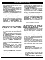
Overview
Used with the Trilogy Networx™ series door locks and
keypads, DL-Windows version 4.0.0 software (or later)
allows you to upload and download programming features wirelessly using a computer network.
With
"wireless" communication, the various cables and/or an
AL-DTM Data Transfer Module are NOT required to
transfer data between DL-Windows and the wireless
locks. With a few clicks of the mouse, you can use your
computer to retrieve logs, download User Codes and
program features into and out of each wireless lock in the
system.
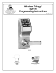
Small Network Support
Lock
#1...
Up to 63 locks for
each Gateway...
GATEWAY
#1
5)
J-4
(R
.1 1
02
ed
s8
Wir
les
W ire
d (R
J-45
)
or W
ireles
s
W
or
io ) )
Rad
Rad
io
)))
)))
))
ire
Router
Lock
#63
E X P A N D A B L E
...Up to 32 Gateways
for each system
PC Running
DL-Windows
Software
Wir
ed
(RJ
-45
ire
les
)
s
or
W
80
2.1
1
GATEWAY
#32
Rad
io )
)))
...Lock
#2000
Large Network Support
Lock
#1...
Up to 63 locks for
each Gateway...
GATEWAY
#1
5)
J-4
1
(R
2.1
ed
80
ir
s
W
W ire
d (R
J-45
)
or W
irele
ss
PC Running
DL-Windows
Software
Existing
Corporate
Ethernet
Network
or
io ) )
Rad
Rad
io )
)))
)))
)
s
ele
W ir
Lock
#63
To ensure each physical lock is identified correctly by
DL-Windows, the factory assigns each lock a unique Serial Number; after locks are installed on the doors and
the Gateways are mounted, the Gateways search for
new locks, allowing them to be enrolled into the system.
FLEXIBLE SETUP
In addition to wireless communication, these wireless
door locks can also be programmed at the keypad (see
the keypad programming instructions included with the
lock). This means that locks can be installed on the
doors and immediately be put into use via keypad programming--even before a wireless network is set up.
Therefore, you can install the locks on the doors before
configuring the wireless network, or you can set up the
wireless network first and add locks later. If you wish,
you can even start by designing a "virtual" system within
DL-Windows (creating new Accounts, adding Users and
configuring lock features, etc.), then set up the network
and install the lock hardware later. But in the end, after
your lock hardware is physically installed and the network is up and running, you can run DL-Windows to link
the "virtual" system saved on your computer with the
"real" lock hardware on the doors.
Note: Keypad programming of User Codes, Features,
Time Zones, and Schedules is available as a temporary
convenience to allow the lock to be put into use before
installing and configuring a wireless network. Therefore,
all lock programming added via the keypad cannot be
retrieved into DL-Windows.
If you decide to start
programming your wireless lock via the keypad, we
recommend you keep hardcopy records (in a secure
location) of all Users, their User Codes, and any
proximity cards that may have been programmed. Keeping complete and accurate records saves time because
after the wireless network is set up, any programming
added via the keypad must be re-added to DL-Windows
and downloaded back to the lock(s).
E X P A N D A B L E
...Up to 32 Gateways
for each system
CAPACITY
Wir
ed
or
(R
W ir
J-4
ele
5)
ss
80
2.1
1
GATEWAY
#32
Rad
io ) )
))
...Lock
#2000
DL-Windows software is installed on a computer that is
connected to a network (either a small Ethernet network
or large corporate LAN). Connected to this network is an
intermediate device called a Gateway that communicates
via a private wireless signal to a radio located inside
each door lock. In this way, the software allows full programming and control of each lock in the system. Note:
In this manual, the word "lock" refers to all Networx™ series door locks and the NETWORXPANEL wireless control panel and its wireless keypads.
DL-WINDOWS™ for Trilogy Networx™ V4.0 USER'S GUIDE
Each installed system can contain from 1 to 32 Gateways--and each Gateway can control up to 63 locks--for
a maximum of 2000 locks allowed per Account; and the
DL-Windows software can support, in theory, an unlimited number of Accounts. In addition, each Networx™
lock can contain up to 5000 Users!
MINIMUM WIRELESS SYSTEM
As shown in the overview drawings at left, you do not
need a massively complex corporate network to run a
working system. In fact, a minimum wireless system
may consist of a laptop or desktop computer (to run
DL-Windows), a home router (to allow connection to a
computer network), and an Alarm Lock Gateway module (the intermediary between the network and the
3
Overview (cont'd)
locks). Although you can set up the wireless network
first and add locks to the doors later, for the sake of
convenience it is recommended that you have at least
one Networx™ lock installed on a door before setting up
your wireless system.
NETWORK SECURITY
The system uses AES (Advanced Encryption Standard)
to protect the integrity of the data flow between the wireless router/network and the Gateways.
HOW TO USE THIS MANUAL
DL-Windows software is the basis for wireless lock
programming. For those unfamiliar with using DLWindows software, stop here and review the DLWindows User Guide (OI237). It may be helpful to create a "test" Account in DL-Windows while walking
through the examples presented in this User Guide and
in OI237.
If you are already familiar with DL-Windows, the transition to working with wireless locks will be straightforward
with slight changes in terminology. If you want to get
started right away to see the system work, see the Quick
Start Guide (OI362). This manual can be read from beginning to end, or can be used with the table of contents
as a reference manual.
●
To install locks on the doors first, use the Installation Instructions for the lock model you wish to install,
then use the keypad Programming Instructions to put
the locks into use.
●
To set up the wireless network system and connect the network to DL-Windows, go to the "Start
Here" section on page 7.
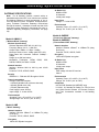
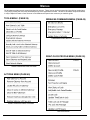
ORDERING INFORMATION
Several Gateway device models are available; all have
the two antennas used to transmit to the locks via an
Alarm Lock proprietary radio connection.
● Gateway "Wireless/Wired" AL-IM80211 - Hardwired/
Wireless Gateway Interface Module. Supplied with its
own Class 2 transformer to supply power; connection to
a network is supported via either a wired connection
(using a standard RJ-45 Ethernet cable) or a wireless
connection (using a third antenna for 802.11 transmissions). Ensure adequate 802.11 coverage in the area
where the "Wireless/Wired" Gateway is mounted. Supports up to 63 Networx Locks. Ceiling- or wallmountable.
● Gateway "Wired" AL-IME - Hardwired Gateway Interface Module, supports up to 63 Networx Locks, connects directly to a network using a standard RJ-45
Ethernet cable. Ceiling- or wall-mountable; powered
4
with Class 2, 6VAC transformer (supplied).
● Gateway "Power over Ethernet" AL-IMEPOE - Hardwired Gateway Interface Module + POE (Power Over
Ethernet), supports up to 63 Networx Locks, connects
directly to a network using a standard RJ-45 Ethernet
cable and POE. Ceiling- or wall-mountable.
● Gateway "Plenum Rated POE" AL-IMEPOEP - Same
as above "AL-IMEPOE", with added enclosure protections and installation hardware for mounting above
"drop-ceiling" tiles or other locations subject to air pressure changes (HVAC air-filled spaces, etc.).
● PDL6100/26D - Cylindrical Trilogy® Networx™ Wireless
Access Control Lock with built in HID Proximity ID Card
Reader, full-metal digital keypad, integral bi-directional
radio, 4 C-cell battery-operated (batteries supplied), serial number ID card, standard format SCI keyway for
manual key override, 4⅞" ASA Strike (included).
● DL6100/26D - Cylindrical Trilogy® Networx™ PIN-Code
Wireless Access Control Lock, as above, with metal
digital keypad only. Standard format SCI keyway for
manual key override, 4⅞" ASA Strike (included).
● PDL6500 - Mortise Trilogy® Networx™ Wireless Access
Control Lock with built in HID Proximity ID Card Reader,
full-metal digital keypad, integral bi-directional radio,
supplied batteries and serial number ID card. Standard
format SCI keyway for manual key override, 4⅞" ASA
Strike (included).
● DL6500 - Mortise Trilogy® Networx™ Wireless Access
Control Lock with full-metal digital keypad, integral bidirectional radio, supplied batteries and serial number
ID card. Standard format SCI keyway for manual key
override, 4⅞" ASA Strike (included).
● PL6100 - Cylindrical Trilogy® Networx™ Wireless Access Control Lock with built in HID Proximity ID Card
Reader (keypad removed for added security), integral
bi-directional radio, 4 C-cell battery-operated (batteries
supplied), serial number ID card, standard format SCI
keyway for manual key override, 4⅞" ASA Strike
(included).
● PL6500 - Mortise Trilogy® Networx™ Wireless Access
Control Lock with built in HID Proximity ID Card Reader
(keypad removed for added security), integral bidirectional radio, supplied batteries and serial number
ID card. Standard format SCI keyway for manual key
override, 4⅞" ASA Strike (included).
● ETPDLN, ETDLN & ETPLN - Networx™ Wireless standalone access control exit trims add convenience, programming, flexibility and audit trail to most major manufacturers exit devices. Ideal for securing exterior doors
in schools, hospitals and commercial buildings, Trilogy
Exit Trims are feature rich with audit trail, multi-users
and auto lock/unlock capabilities. For the highest security measures, the ETPDLN is outfitted with both PIN
and HID Prox technology. Both ETDLN and ETPDLN
locks come with a rugged, 12-button metal keypad and
a non-handed fully field reversible clutch mechanism to
DL-WINDOWS™ for Trilogy Networx™ V4.0 USER'S GUIDE
Overview (cont'd)
insure long life and durability. Add, delete, change users at the keypad or use our DL Windows software to
manage your system at the PC with ease. Our Trilogy
Exit Trims grant access for up to 2000 users, provide
40,000 event audit trail and 500 lock/unlock scheduled
events with time zone support. Also available for purchase is our proximity-only Exit Trim model (ETPLN).
● NETDK, NETPDK & NETWORXPANEL - The NETDK
and NETPDK (with proximity card reader) are secured
single-door or double-door digital keypads for use within
the wireless Networx™ system. One or two keypads
can be wired to the dedicated NETWORXPANEL control panel to provide controlled access to a door by releasing a locking device (such as a magnetic lock or
electric door strike) when a proper User Code (and/or a
proximity credential to the NETPDK) is presented. The
NETWORXPANEL inputs support two of any combination of NETDK or NETPDK keypads, PLUS up to two
Wiegand devices. See WI1881, WI1855 and WI1856
for additional information.
● DL-WINDOWS - Alarm Lock Trilogy Microsoft Windowsbased software application, v4.0.0 or higher, supports
Trilogy Networx and Trilogy Standalone Locks, with single database. Free of charge and downloadable online
at www.alarmlock.com.
● OI362 - Wireless Quick Start Guide.
● OI352 - Wireless Network Setup & DL-Windows Configuration Instructions (this manual).
● WI1790 - PDL6100 Keypad Programming Instructions.
● WI1820 - DL6100 Keypad Programming Instructions.
● WI1835 - PDL6500 & ETPDLN Keypad Programming
Instructions.
● WI1844 - PL6500 & ETPLN Programming Instructions.
● WI1674 - PDL6100 and DL6100 Installation Instructions.
● WI1676 - PDL6100 and DL6100 Door Installation Template.
● WI1881 - NETDK & NETPDK Installation Instructions
● WI1855 - NETWORXPANEL Programming Instructions
with the NETDK & NETPDK keypads
● WI1856 - NETWORXPANEL Installation Instructions
See www.alarmlock.com for a complete list of all available standard Trilogy and Networx™ series devices and
manuals (downloadable in PDF format).
DL-WINDOWS SYSTEM REQUIREMENTS
The DL-Windows application has been tested and approved for an IBM-compatible P4 1.6GHz computer with
256MB RAM and a minimum of 100MB of hard drive
space running Microsoft Windows 98, 2000 or XP with
one unused RS-232 Serial Communications port (COM
1-4) required. If a COM port is unavailable, please contact customer support for one of our USB adapters
(MX1130 or ALPCI2-U). Depending on your system demands, a slower PC may function properly but with significant user interface problems, including long intervals
for the system to respond.
Important: DL-Windows is not a client-server application (i.e. is not multi-user). The program and its database must be installed and maintained on a single PC.
● WI1836 - DL6500 & ETDLN Keypad Programming Instructions.
● WI1843 - PL6100 Programming Instructions.
DL-WINDOWS™ for Trilogy Networx™ V4.0 USER'S GUIDE
5
Gatew ay Specifications
GATEWAY SPECIFICATIONS
Note: For all Gateway modules, network activity or
bandwidth usage does NOT occur until the user operates
DL-Windows software to send programming to (or receive log data from) locks. Exception: During the Emergency Lockdown Command, Gateways communicate
through the network. Gateways will send less than 1000
bytes during these Emergency Commands (for more information regarding Emergency Commands, see page
49).
AL Radio Link
900MHz GFSK
50 Channels
10mW power output
Input Power
Voltage: 5 - 6 volts AC/DC
Environmental
Operating Temp: -20° to 60°C (-4° to 140°F)
Storage: -40° to 85°C (-40° to 185°F)
Model AL-IMEPOE
Model AL-IM80211
("Wireless/Wired" Gateway)
Wireless Specifications
Wireless Standards: IEEE 802.11b; 802.11g
Frequency Range: 2.412 – 2.484 GHz
Output Power: 14dBm +1.5 dBm/-1.0 dBm
Maximum Receive Level: -10dBm (with PER < 8%)
Data Rates with Automatic Fallback: 54Mbps –
1Mbps
Range: Up to 328 feet indoors
Modulation Techniques: OFDM, DSSS, CCK,
DQPSK, DBPSK, 64 QAM, 16 QAM
Network Interface
Interface: Wireless 802.11b, 802.11g and 10/100
Ethernet
Protocols: TCP/IP, UDP/IP, DHCP
Security
IEEE 802.11 - PSK with AES Encryption 128-bit
Power Consumption
Average Power Consumption:
● 1300mW (WLAN mode; maximum data rate)
● 300mW (WLAN mode; idle)
● 750mW (Ethernet mode)
Peak Supply Current: 650mA
Input voltage: 5 - 6 volts AC/DC
Environmental
Operating Temp: -20° to 60°C (-4° to 140°F)
Storage range: -40° to 85°C (-40° to 185°F)
("Power Over Ethernet" Gateway)
Model AL-IMEPOEP
("Plenum Rated POE" Gateway)
Network Interface
Interface: Ethernet 10Base-T or 100Base-TX (using
RJ-45 jack)
Protocols: TCP/IP, UDP/IP, DHCP
Encryption
128-bit AES Rijndael encryption
AL Radio Link
900MHz GFSK
50 Channels
10mW power output
Input Power
POE Voltage: 48 volts DC nominal
Class 2
Environmental
Operating Temp: -20° to 60°C (-4° to 140°F)
Storage: -40° to 85°C (-40° to 185°F)
Compliance
802.3af POE Standard (AL-IMEPOEP only)
UL 2043: UL Standard for Safety Fire Test for Heat
and Visible Smoke Release for Discrete Products
and Their Accessories Installed in Air-Handling
Spaces
Model AL-IME
("Wired" Gateway)
Network Interface
Interface: Ethernet 10Base-T or 100Base-TX (using
RJ-45 jack)
Protocols: TCP/IP, UDP/IP, DHCP
Encryption
128-bit AES Rijndael encryption
6
DL-WINDOWS™ for Trilogy Networx™ V4.0 USER'S GUIDE
S TA R T H E R E
This section will help you define the steps required to suit the
specific needs of your installation. Let's start with the big questions first, because the installation steps that follow depend on
your answers. Note: The underlined words are defined in the
Terminology section on page 9.
PRELIMINARY QUESTIONS
You may not have answers to the following questions now,
but understand that they are intended to encourage thought
and help evaluate your needs.
Are you planning to use a large Corporate Network or
a smaller network provided by single router?
Smaller networks permit the dynamic assignment of IP
addresses by DHCP; larger networks may require static
(fixed) IP addresses be reserved by your network administrator.
Will you use "Emergency Commands"?
Three Emergency Commands are available in your wireless system: "Global Lock Down" locks all doors in the
system; "Global Passage" unlocks all doors in the system; "Return to normal" exits these Emergency Commands. Emergency Commands will NOT work if you use
DHCP (static IP addresses are required). For more information regarding Emergency Commands, we strongly
recommend you familiarize yourself with this topic on
pages 49-53, and also with the Tools menu and its ability
to send the IP Table to selected (or all) Gateways on page
37.
Will your Gateways need to communicate across multiple Subnets?
To improve security and processing performance, network
administrators often divide their corporate Intranets into
interconnected but separate segments called "subnets".
If the answer to ANY ONE of the above questions is
"yes", we recommend static IP addresses be reserved
for exclusive use by your Gateways. If the answers are
"no" for all of the questions, and you want to use a smaller
network provided by a router, you can assign static IP addresses yourself using the instructions that came with your
router; if you want to use a corporate network, you must contact your network administrator to have static IP addresses
reserved for your use.
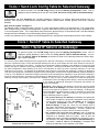
SUBNETS
Use the following information when installing multiple wireless
Networx Gateways within a corporate Intranet that contains
multiple "subnets".
To improve security and processing performance, corporate
Intranets are often divided into interconnected but separate
segments called "subnets". The IP (Internet Protocol) address is a unique address of a device (such as a computer or
a Gateway) connected to a TCP/IP corporate Intranet.
DL-Windows can only Discover Gateways when the Gateways are connected to the same subnet to which DLWindows is also connected.
IP addresses are written as four groups of numbers separated by periods; these groups are called "octets". IP addresses can be permanent ("static") or dynamically assigned
DL-WINDOWS™ for Trilogy Networx™ V4.0 USER'S GUIDE
(by DHCP) when a device, such as a Gateway, is powered.
Class B Subnets
Some corporate Intranets contain multiple "Class B" subnets;
the "Class B" refers to the octet that does not change, if naming each octet from left to right. An example of two "Class B"
subnets where the first two octets of each network IP address
remain the same are:
A
B
C
D
● Subnet 173.16.100.xxx
● Subnet 173.16.200.xxx
In this example, the "A" and "B" octets "173" and "16" are the
same within the network. (Note: The "xxx" is a way of showing a variable number).
Subnet
173.16.100.xxx
Subnet
173.16.200.xxx
ROUTER or
SWITCH or SERVER
GATEWAY
GATEWAY
GATEWAY
GATEWAY
GATEWAY
GATEWAY
PC Running
DL-Windows
Software
GATEWAY
GATEWAY
GATEWAY
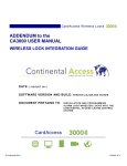
GATEWAYS ON DIFFERENT SUBNETS WITHIN A NETWORK
As shown in the image above, if the computer running DLWindows is connected to the first subnet (173.16.100.xxx),
and several Gateways are connected to the second subnet
(173.16.200.xxx), DL-Windows will ONLY be able to communicate with the Gateways on the second subnet when:
● ALL Gateways use only static IP addresses, and
● The network administrator allows for open addressing
between the two subnets in the network
The network administrator may decide to use routing tables
or may specify blocks of addresses through which the two
subnets can freely communicate in both directions. Regardless of the method selected, your network administrator must
determine the range of network addresses to assign to the
Gateways and to the DL-Windows computer. As shown below, three address fields must be obtained from your network
administrator: IP Address, Subnet Mask, and Default Gateway.
Why we recommend using static IP addresses
We recommend using static IP addresses for each Gateway
you install because they have the following advantages:
● DL-Windows software performs more smoothly because
the software does not have to waste time re-locating
Gateways that have had their IP addresses changed by
DHCP;
● Static IP addresses allow operation across subnets in
7
S TA R T H E R E ( c o n t ' d )
large corporate networks (such as those that exist between buildings);
● Static IP addresses allow Emergency Commands (such
as "Emergency Lockdown") to be used (see Emergency
Commands on page 49);
Contact the Network Administrator
If you know that you will install your wireless Networx system within a large corporate network that includes multiple
subnets, we recommend you start by contacting the corporate network administrator and request the following:
●
IP Address - An address for each Alarm Lock Gateway
device
__________________________________________
●
Subnet Mask - Filtering data (mask bits) as required by
the aforementioned IP Address
__________________________________________
●
Default Gateway - The address of the physical device,
such as a router, for the current subnet to which DLWindows will be connected
__________________________________________
In addition, inquire about wireless authentication and encryption, as required.
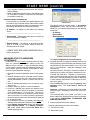
ASSIGNING STATIC IP ADDRESSES
TO GATEWAYS
DL-Windows can only Discover Gateways when the Gateways are connected to the same subnet to which DLWindows is also connected. To allow DL-Windows residing
on one subnet to communicate with Gateways located on a
second subnet (with both subnets located within a single
network) a typical installation strategy is:
1. Estimate the number of Gateways needed in the installation.
2. Install DL-Windows on a PC connected to the first subnet
(for example, plug the PC into a wall network outlet the
network administrator confirms is wired to the first subnet).
3. Open DL-Windows and create a new (or open an existing) Account.
4. Create a virtual lock "Profile" for each lock installed.
5. Power up a Gateway and connect the Gateway to the
same (first) subnet to which DL-Windows is connected
(in the example above, "173.16.100.xxx"). This connection to the first subnet may be through a second network
socket in the wall, or to a router (or switch) connected to
the same network socket in the wall that the DL-Windows
PC is also connected.
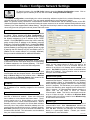
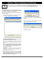
6. In DL-Windows, discover the Gateway and Assign the
Gateway to the selected DL-Windows Account.
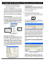
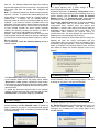
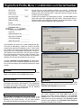
7. In the Gateway Configuration screen, click Tools, Configure Network Settings. In the Network Configuration screen, (shown below) uncheck Use DHCP, and a
warning popup appears:
8
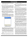
WARNING POPUP
Click Yes to close the warning popup. In the Network
Configuration screen, type the three addresses obtained from your network administrator into the following
three fields:
●
●
●
IP Address
Subnet Mask
Default Gateway
Default
NETWORK CONFIGURATION SCREEN
Click Save Configuration and send to Gateway.
8. Physically disconnect (unplug) the Gateway from the first
subnet, physically relocate and plug the Gateway into the
second subnet (in the example above, from "173.16.100.
xxx" to "173.16.200.xxx). Install the Gateways in their
final locations.
As stated previously, Emergency Commands require all
Gateways in the system use static IP addresses to communicate with each other. Therefore, to ensure Emergency Commands operate correctly, use the following
menu item to manually distribute the static IP addresses
of each Gateway (listed within DL-Windows) to all Gateways in the system.
Click the GW Confg button to open the Gateway Configuration screen. Click Tools, Send IP Table to all
Gateways.
Important: All Emergency Commands MUST be tested
weekly (or daily if necessary) to ensure their correct operation.
The remaining tasks are to install your locks on the
doors, and have DL-Windows Discover them (as outlined
in the section CONFIGURING DL-WINDOWS FOR
WIRELESS LOCK USE):
9. Discover physical locks on the Gateway.
10.Assign (add) discovered locks to the Gateway.
11. Link lock to a Profile.
12. Send Profile to lock.
DL-WINDOWS™ for Trilogy Networx™ V4.0 USER'S GUIDE
Te r m i n o l o g y
The following words are used throughout this manual to convey specific concepts and/or actions used in DL-Windows
version 4.0.0 software (or later).
Assign - Add to hardware or specify a relationship. Can be
used with User Codes and locks ("to assign User Codes to
specific locks"), or with hardware identification ("the factory
assigns each lock a unique Serial Number"), or a fixed wireless communication channel between locks and a Gateway
("locks assigned to a Gateway").
Communicate - To send or receive a transmission. To avoid
the directionally confusing terms of "download" and
"upload", the word "communicate" is used in this guide.
Configure- To "assign" (add) discovered physical locks to a
Gateway (by sending the "Lock Config Table" to the selected Gateway). Configuring ensures a fixed wireless
communication channel exists between selected physical
locks and a selected Gateway.
The Gateway Configuration screen allows you to select a
Gateway and allow that Gateway to discover physical locks;
these physical locks can then be assigned to that selected
Gateway. When the Use Selected Locks button is clicked
(in the "DISCOVERED LOCKS" POPUP), the Gateway
are connected to a network. It eliminates having to
manually assign fixed IP addresses.
Discover - To "discover" Gateways, the system searches for
Gateways not yet assigned to an Account; to "discover"
locks, the selected Gateway searches for locks not yet assigned to Gateways.
Download - See Communicate.
Import - When the Account information stored in DL-Windows
is lost (such as with a stolen laptop)--AND--the DLWindows backup files are either non-existent, inadequate or
lost, the "Import" options can be used to rebuild an existing
wireless system using the data stored inside the onboard
memory of the installed Gateway device(s). See the Tools,
Import menu options on page 38 for more information.
IP Address - The IP (Internet Protocol) address is a unique
address of a device (such as a computer or a Gateway)
connected to a TCP/IP corporate Intranet. IP addresses
are written as four groups of numbers separated by periods; these groups are called "octets". IP addresses can be
permanent ("static") or dynamically assigned (by DHCP)
when a device, such as a Gateway, is powered.
Link - In DL-Windows, the word "Link" is used to describe the
specific action of associating a "virtual lock" Profile to the
serial number of the physical lock installed on the door.
Locate - With physical lock(s), the Locate command causes
the physical lock to "beep" and flash its LED (helpful when
you wish to find the physical lock or confirm the lock's wireless connection is operational). When used with a Gateway, refers to re-discovering a "lost" Gateway device on the
network. Used when an operational Gateway has lost its
network connection, and appears listed in red colored text
on the Gateway Configuration screen.
"DISCOVERED LOCKS" POPUP
sends "configuration data" to the selected locks. This
"configuration data" contains items (such as an internal lock
designation, a specific radio channel and security data) that
are all embedded in what is called a "Lock Config Table".
This "configuration data" instructs the physical lock(s) to
communicate ONLY with that Gateway and prevents other
Gateways from communicating with the physical lock(s).
In short, the Gateway tries to "configure" the selected physical locks by assigning the selected physical locks to the
Gateway.
DHCP (Dynamic Host Configuration Protocol) - Software
that automatically assigns IP addresses to devices that
DL-WINDOWS™ for Trilogy Networx™ V4.0 USER'S GUIDE
Lock Config Table - When a Gateway is "discovered" and
added to an Account, DL-Windows sends a Lock Config
Table to the Gateway. This Lock Config Table is stored in
the Gateway memory, and may or may not contain assigned physical lock data. The table is a database structure
that is designed to hold the physical lock data (serial numbers, etc) when physical locks are "assigned" to the Gateway.
Physical - Same as "Real". Tangible, not virtual. See Virtual.
Profile - Lock "Profiles" may also be called "Lock Programs"
or "Virtual Locks". A lock "Profile" can be thought of as a
"virtual" lock, created within DL-Windows, that contains all
of the instructions that a "real" ("physical") lock uses to perform its various functions. Use DL-Windows to create a
lock "Profile" on your computer, then transfer and store the
"Profile" in the memory of the "real" lock. The lock "Profile"
is essentially a computer database file that maintains User
Codes, Features, Time Zones and Schedules. When creating these virtual lock Profiles, you are also designing the
entire virtual system--conceptualizing which doors will have
which locks, adding User names and allowing or restricting
9
Te r m i n o l o g y
access to the virtual locks by the various Users in the Account.
Real - Same as "Physical". Tangible, not virtual. See Virtual.
Subnet (SUBNETwork) - To improve security and processing
performance, network administrators often divide their
corporate Intranets into interconnected but separate segments called "subnets". Subnets also allow multiple users to access the Intranet with the same subnet address.
A router is typically used to allow network traffic to pass
between subnets.
Subnet Mask - The IP protocol makes use of a Subnet
Mask to more efficiently route packets to their correct
network destinations. When a Gateway receives a data
packet, the Subnet Mask indicates how many bits of the
packet's destination address are to be used for routing
and which bits are to be "masked" (ignored). The Subnet Mask can be thought of as a "filter" that allows the
system to ignore unnecessary information, thus increasing efficiency. This information must be obtained from
your network administrator.
Upload - See Communicate.
Virtual - Simulated on a computer. DL-Windows allows you to
create a lock "Profile" that can be thought of as a "virtual"
lock, created within DL-Windows, that contains all of the
data that a "real" (physical) lock uses to perform its various
functions. When creating these "virtual" lock Profiles, you
are also designing the entire "virtual" system-conceptualizing which doors will have which locks, adding
User Names and allowing or restricting access to the virtual
locks by the various Users in the Account. Later, you will
"Link" these lock Profiles with the real locks installed on the
doors.
10
DL-WINDOWS™ for Trilogy Networx™ V4.0 USER'S GUIDE
Hardware Installation
HARDWARE INSTALLATION
For a minimum wireless system, you need:
• A laptop or desktop computer (to run DL-Windows)
• A wired or wireless home router (to allow connection to a computer network)
• An Alarm Lock Gateway module (the intermediary
device between the network and the locks)
Note: Before proceeding, you should have a working
knowledge of DL-Windows. See the DL-Windows
User Guide (OI237) for basic information such as
how to install and open DL-Windows, how to create
Accounts, how to add Profiles to Accounts, etc.
1. Install the DL-Windows software into your computer as described in the DL-Windows User Guide
(OI237).
2. Connect your computer to a network
If you want to set up a "small network" with a router,
follow the instructions "Small Network" that follow. If
you want to use a "large network" such as an existing
corporate Ethernet (such as a LAN), skip down to the
"Large Network" section, below.
SMALL NETWORK
You can create your own "small network" by using a
wired or wireless router.
For the connection between your computer and a
large Ethernet network, most laptops and some
desktop computers contain a wireless network card
(also called a "wireless network interface controller")
to allow for wireless communication between your
computer and a this large network. Contact the network administrator for this kind of wireless connection.
For computers without a wireless network card, connect the "non-wireless" network card in your computer to the network as follows: Connect one end of
the Ethernet cable to the computer network card RJ45 socket (usually located at the back of your computer); connect the other end of the cable to the RJ45 socket at a wall jack or a modem that is part of the
corporate Ethernet network / LAN. Note that wall
jack or modem access points usually need to be configured first by the network administrator before the
network will allow a connection.
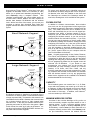
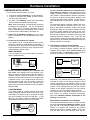
3. The Network Connection to the Gateway
The connection between the network (the router or
the existing corporate Ethernet network) and the
Gateway device may be either directly wired using
an Ethernet cable --or--wirelessly via 802.11x transmissions, as shown in the illustrations below:
Router
Wired (RJ-45)
Router
Wired (RJ-45)
or Wireless 802.11
GATEWAY
#1
or Wireless 802.11
PC Running
DL-Windows
Software
For the connection between your computer and
the router, most laptops and some desktop computers contain a wireless network card (also called a
"wireless network interface controller") to allow for
wireless communication between your computer and
a wireless router; if your computer does not have a
wireless network card, you can usually connect the
"non-wireless" network card in your computer to the
router using an double-ended RJ-45 to RJ-45 (8P8C)
Ethernet cable.
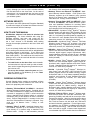
LARGE NETWORK
If you have access to a "large network" such as an
existing corporate Ethernet network (such as a LAN),
connecting to a network may be as simple as plugging your computer into an RJ-45 wall jack. In this
case, you may wish to contact the Ethernet network
administrator and inform them as to your plans.
Wired (RJ-45)
or Wireless 802.11
PC Running
DL-Windows
Software
Existing
Corporate
Ethernet
Network
DL-WINDOWS™ for Trilogy Networx™ V4.0 USER'S GUIDE
Existing
Corporate
Ethernet
Network
Wired (RJ-45)
or Wireless 802.11
GATEWAY
#1
Remember, the Gateway device will eventually be
mounted on a wall or in a ceiling; therefore a wired
network connection to the Gateway device is relatively straightforward because once you plan the final
location of the Gateway and you plan the physical
location of the network connection, the only remaining task is to run a wire between these locations.
The instructions for the wired connection are in the
next section; for wireless connection instructions,
skip to the "Wireless Network Connection to the
Gateway" section below.
Wired Network Connection to the Gateway
The double-ended Ethernet cable is used to connect
the network to any of the Gateway models. Simply
plug one end of the Ethernet cable into the network
Router or a network wall socket (at any location
within the premises) or network modem. Then connect the other end of the Ethernet cable into the
11
Hardware Installation (cont'd)
Gateway module. Now skip to step 4 below, and
read about the importance of selecting a favorable
Gateway mounting location and signal strength considerations.
Wireless Network Connection to the Gateway
This wireless connection will only work with a
"Hardwired/Wireless" Gateway model AL-IM80211.
To ensure a fixed wireless communication channel
exists between the network and the Gateway, you
must first temporarily connect the network to the
Gateway with an Ethernet cable.
Why? When the Gateway is first powered, the very
first thing the Gateway tries to do is obtain an IP Address--from anywhere. If an installation takes place
in a facility that contains several active networks
(and/or active routers), there is a possibility that an
unknown network (or router) will provide the Gateway
with an IP address outside the network you want to
use.
The solution is to temporarily connect the desired
network to the Gateway with the double-ended
Ethernet cable. This temporary wired connection ensures that all network settings (that you want to use)
are sent DIRECTLY into the Gateway, thus ensuring
that the Gateway device will ONLY communicate with
that specific router or network.
3a. Connect the network to the Gateway with an
Ethernet cable. Plug one end of the Ethernet cable into the network Router or a network wall
socket (at any location within the premises) or
network modem. Connect the other end of the
cable to the Gateway module.
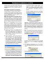
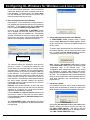
3b. Open DL-Windows. Create a new Account or
select an existing Account. Add a New Lock Profile to the Account. In the New Lock Profile
screen, select a Networx™ "Lock Type" (for example "DL6100"). Click the GW Confg button.
For all new Accounts and existing Accounts without passwords, a popup appears requesting that
you set a "Security Password". For existing Accounts with Passwords, this popup will not appear, therefore jump to step "3c" below.
The above popup appears because there must
be a way for DL-Windows to differentiate between separate wireless Accounts. For example,
if a large office building has one company on the
15th floor and another company on the 16th floor,
radio signals can overlap from these two separate Accounts. How does DL-Windows prevent
12
this confusion between wireless signals? The
answer is to require a unique "Security Password" for each Account that contains wireless
locks, and to embed that password within the radio transmissions.
(Click OK to close this
popup).
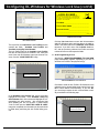
On the DL-Windows main screen, click Tools,
Set Security Password, and the Set Security
Password dialog appears:
SET SECURITY PASSWORD DIALOG
Important: Do NOT share passwords between Accounts, otherwise the radio signals can become intermixed! Be sure you record--in writing--all Account
passwords in a safe location; once set, passwords are
NOT retrievable from DL-Windows! Changing a password in a wireless system requires all wireless locks in
the Account to be manually cleared of all data and reenrolled.
Note: The password must be exactly 6 characters (no
more--no less) in length. Retype the same password in
the Confirm field; click OK to save the password, or
click Cancel to exit without saving. Click OK and a
confirmation popup appears:
Click OK to close the above popup, then click the GW
Config button to open the Gateway Configuration
screen.
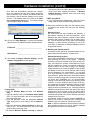
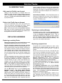
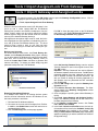
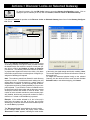
3c. In the Gateway Configuration screen, click the Discover New Gateways And Auto Add to Account
button:
A Discover New Gateways popup appears.
DL-WINDOWS™ for Trilogy Networx™ V4.0 USER'S GUIDE
Hardware Installation (cont'd)
Click Yes and DL-Windows searches the network;
since the Gateway has this direct (albeit temporary)
wired connection to the network, DL-Windows will find
this Gateway, and will add the Gateway to the current
Account. The Gateway will then be listed in the Gateway Configuration Screen grid. The following image
is an example of what will appear:
We recommend to use "MAC Address Filtering" for security if your router supports this feature. If Wireless
Network Security is desired, refer to the router setup
for wireless security.
If NOT using DHCP:
● If you are using Static IP Addresses, refer to the router
setup guide for static IP address setup information.
3f. Disconnect the Ethernet cable from the network Router
(or network wall socket) and also from the Gateway
module.
Click the row to highlight and select the Gateway.
3d. Click on this "New Gateway 1" to select this Gateway.
Write down the IP Address and MAC Address shown.
Gateway ID Card
We recommend that when installing the Gateway, a
blue-colored "Gateway ID Card" be completed. Since
Gateways are often installed in ceilings or other hidden
locations, their physical locations may be easily forgotten. This ID card may prove very useful when replacing
Gateways, or when selecting a Gateway to use to discover locks, or whenever an installed Gateway needs to
be physically located.
IP Address _______________________________
MAC Address _____________________________
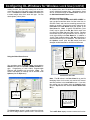
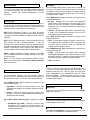
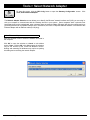
3e. Click Tools, Configure Network Settings, and the
Network Configuration screen appears:
If using DHCP:
● From the Wireless Mode pull-down, click Wireless
Only.
● Type the network name in the Network Name (SSID)
field. For more information, refer to the setup guide for
the router being used.
● From the pull-down, select the appropriate Network
Type being used, in most cases it will be Infrastructure.
● Select the appropriate Channel Number for which the
router is set. - For more information, refer to the setup
guide for the router being used.
● By default, Wireless Network Security is disabled.
DL-WINDOWS™ for Trilogy Networx™ V4.0 USER'S GUIDE
4. Mounting the Gateway module
A Gateway module acts as an interface between a computer network and the Networx™ wireless locks.
Gateway Mounting Location
Give careful consideration to the location of the Gateway
when planning the layout of the system. Gateways
should be mounted in elevated areas (such as drop ceilings), and should be centrally located within the separate lock installations. Select a convenient location that
allows access to an AC outlet (to plug in the Gateway
supply transformer for models AL-IM80211 and AL-IME)
and allows access to the RJ-45 Ethernet cable running
from the Gateway to the router/network. You can plan
for a single Gateway to cover a circle several hundred
feet in diameter, greater within open areas without walls.
Choose a location as high above ground level as practical (home attic installations are not recommended),
keeping in mind that metal objects may adversely affect
reception. It may be helpful to draw a layout of the system, identifying all proposed Gateway locations and the
anticipated door locations. Also include notations indicating construction materials in use. Although wood and
wallboard construction will have little effect upon signal
strength at the lock, concrete or brick can reduce signal
strength by up to 35%, while steel-reinforced concrete or
metal lath and plaster can reduce Gateway transmitter
strength as much as 90%.
All Gateway models should be mounted vertically on
either a wall or ceiling. Horizontal "flat" mounting of the
Gateway enclosure should be specifically avoided.
Note: In difficult installations wherein distant Gateways
pose reception problems, the use of multiple gateways
throughout the premises is recommended.
13
Hardware Installation (cont'd)
First Time Gateway Power Up
We supply a "Class 2" 6V power supply (never substitute power supplies; use only the supplied unit) that is
wired to the terminal strip located on the Gateway PC
board. Wiring is non-polarized, so connect either wire to
either of the two terminals.
When the Gateway is first powered, the red light flashes
slowly (about once every 2 seconds), indicating the unit
is looking for a valid IP address (unit may take up to 90
seconds to find a valid address). If the unit finds a valid
IP address prior to 90 seconds, the red light flickers.
If the unit does not obtain a valid IP address after 90
seconds, the flashing rate increases to one flash per
second, and will attempt to find an IP address later.
The one flash per second flash rate indicates the Gateway is "configured". At this point you can reset the GW:
Reset the Gateway
At this point, the Gateway is mounted and connected to
the router (or the network) with the RJ-45 cable. Apply
power to the Gateway and the red light flashes slowly,
about once every 2 seconds. Before securing the Gateway housing cover, reset the Gateway memory--even if
the Gateway has never been used. Press and hold the
"RESET" button and the red light turns on continuously;
continue to hold the button and the red light will start to
flicker. Release the button and the red light will continue
to flicker.
"Resetting" the Gateway clears all memory and ensures
that any residual voltage or test data existing from the
factory is cleared from the unit. Always reset the Gateway for new installations; you can also reset the Gateway anytime after the Gateway is powered. Secure the
Gateway housing cover with the screws provided.
Note: See page 25 for additional information regarding
resetting the Gateway.
14
DL-WINDOWS™ for Trilogy Networx™ V4.0 USER'S GUIDE
Configuring DL-Windows for Wireless Lock Use
CONFIGURING DL-WINDOWS FOR
WIRELESS LOCK USE
Now that the wireless network hardware is installed, you can
use DL-Windows to design your "virtual" system.
The following list are the simplified steps required in DLWindows to get a minimum system (one Gateway and one
lock) up and running. These numbered steps correspond with
the detailed procedures that follow:
1.
2.
3.
4.
5.
6.
7.
8.
Create a new Account
Create a virtual lock "Profile"
Discover the Gateway
Add ("Assign") the Gateway to an Account
Discover physical locks on the Gateway
Assign (add) discovered locks to the Gateway
Link lock to a Profile
Send Profile to lock
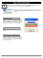
(For new installations, a popup appears with directions).
First click OK to clear the popup, then, as directed by the
popup, use your mouse to right-click anywhere in this
white box (the "Account Tree" area at the left), and select
New Account. The New Account dialog opens.
Enter New Account Description
Enter the New Account Description in the field shown
in the "NEW ACCOUNT DIALOG" image. The Account
Description will typically be the name of the company or
facility where a lock(s) will be installed. Note that existing
Accounts from previous installations are also displayed.
Click OK to create this new Account.
(If you wish to delete an Account, right mouse-click the
name of the Account and select Delete Account from
the menu. A warning popup will appear, and click Yes to
confirm, and click No to cancel).
It may be helpful to create a "test" Account in DL-Windows
while walking through the procedures below; later you can always go back and create a separate Account that accurately
reflects a genuine installation.
1. Create a new Account.
Technically, an "Account" is a DL-Windows computer
database file that allows you to organize and maintain
multiple lock installations. But in practical terms, an Account is often named after the building or company location in which a lock or multiple locks have been installed.
For example, the Account Name might be "Overbrook
Hospital" and listed in that Account are the 4 locks you
just installed on the 7th floor. In DL-Windows, Accounts
can be created, edited, cloned and deleted. The benefit
of an Account is that it allows you to add the name of a
User ONCE and then assign that User to multiple locks
within a building, rather than having to enter and re-enter
the same User information again and again for each lock
in the Account. Enter the name of the User once in the
Global Users screen, then sit back and assign that User
to the locks you wish, with just a few clicks of the computer mouse.
Double-click the DL-Windows shortcut, or click Start,
Programs in Windows to find and start the DL-Windows
software. The DL-Windows main screen opens (see
"DL-WINDOWS MAIN SCREEN" image).
Right mouse-click here and
select New Account
DL-WINDOWS MAIN SCREEN
DL-WINDOWS™ for Trilogy Networx™ V4.0 USER'S GUIDE
NEW ACCOUNT DIALOG
2. Create new virtual "lock Profiles" (also called "Lock
Programs" or "virtual locks"). A lock "Profile" can be
thought of as a "virtual" lock, created within DL-Windows,
that contains all of the instructions that a real lock uses
to perform its various functions. Use DL-Windows to
create a lock Profile on your computer, then transfer
and store the Profile in the lock memory. The lock
Profile is essentially a computer database file that
maintains User Codes, Features, Time Zones and
Schedules.
New Lock Profile
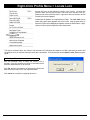
After clicking OK in the New Account dialog, a popup
appears asking if you would like to create a new lock
Profile. Click Yes, and the New Lock Profile dialog appears (see the "NEW LOCK PROFILE SCREEN" image).
Type the description of the new lock, which will typically
be the name of the room in the facility that the lock is securing. Select the Type of Lock to be programmed from
the drop-down list (for example, the 6100 series). When
finished, click OK. After a few seconds, the new Profile
is created and DL-Windows automatically opens the
Global Users screen. Note: To add a new lock to an
15
Configuring DL-Windows for Wireless Lock Use (cont'd)
existing Account, first open any existing lock in the Account, then right-click in the white column and select New
Lock. The Number of Locks to Create? field allows you
to create multiple locks of the same lock type. You can
also duplicate ("clone") locks.
be imported from other DL-Windows Accounts or from
comma delimited formatted lists. Administrative Users
can be accessed through the Global Users screen via
the Add Administrative Users button.
Add Users and User Codes
As shown in the "ADD USERS AND USER CODES" image, type the first and last name of a User in the User Information Fields, and enter the remaining personal information as needed. Note that the names entered in the
First Name and Last Name fields also appear in the
User Name list. Note: A specific PIN Number ("User
Code") may be typed in the Pin No. field for each User
(or typed in the User List area "Pin" column). Random
User Codes may be auto-generated for one or many Users by right-clicking in the User Name list. In addition, a
Custom Field (located under the Pin No. field) allows a
customized field of up to 15 characters. This field is set in
the Options screen (click the Opt button) and once
changed remains identical for all locks in all Accounts.
NEW LOCK PROFILE SCREEN
Using the Global Users Screen
You can always open the Global Users screen with the
Global button (see the "GLOBAL USERS SCREEN" image). Programming of User Codes, Programmable
Features and Schedules can now begin. Note: The
screens that display on StartUp can be selected under
Options (click the Opt button).
User
Information
Fields
The LockID Grid
displays LockID
numbers
Right-click menu in
the User Name list
ADD USERS AND USER CODES
Note: The ID column in the User Name list is used for
identifying Users in this screen only and is NOT associated with positions in the Lock Data screen. If you wish,
this column may be hidden using the Options screen
(click the Opt button and uncheck "Show Global User
ID's").
The Pin may be
added directly to
this column, or
use the PIN No
field.
Lock Grid
To add a selected
User, double-click on a
LockID number box.
GLOBAL USERS SCREEN
The Global Users screen is used to enter User information and to assign Users to specific locks. User lists can
16
LOCK ID GRID
The LockID Grid displays LockID numbers and is colorDL-WINDOWS™ for Trilogy Networx™ V4.0 USER'S GUIDE
Configuring DL-Windows for Wireless Lock Use (cont'd)
coded to describe the state of the selected User:
• Green = User entered in the lock and enabled
• Red = User entered in the lock but disabled
• White = User not in the lock
Double-click on a LockID Grid number to cycle through
the colors of the LockID number (from white to green to
red and back to white again) thus adding, disabling or
removing a User as needed. In this way, the LockID
Grid can be used to add a User to any lock in an Account. One or multiple Users can also be added to one
or more locks via the right-click menu in the User Name
list.
Select a Range of Users
To select a range of Users, click to select the first User,
press and hold the SHIFT key, then click the last User in
the range (you can also press CTRL and click individual
Users). Within the range of Users highlighted, right-click
in the highlighted area to display the menu as shown in
the "SELECT A RANGE OF USERS" image. Click a
selected action in the menu to perform the action for the
selected Users.
To highlight a range of
Users, click in this column
to select the first User,
press and hold the SHIFT
key, then click the last
User in the range…
...then
rightclick and select
from any of
these options.
SELECT A RANGE OF USERS
Random User Code Generation
Random User Codes may be generated for one or many
Users. (Note: To avoid User Number conflicts, it is recommended to first assign specific User Codes to Users
before selecting random User Code generation). To
generate random Codes for multiple users, press and
hold the CTRL key, click the right arrow ("►") located to
the left of the User Name to select each User(s), then
right-click and select "Generate Selected New Codes".
You can select a range of Users (as described above)
and click Generate All New Codes to create new codes
for all Users.
Administrative Users
The Add Administrative Users button displays the Administrative Users screen. Administrative Users are the
same for all locks within an Account. Enter information
the same way as if adding a basic User.
3. Discover new Gateways.
4. Add ("Assign") the Gateway to an Account
Note that steps 3 and 4 are listed together because
these two tasks can be performed with one button, as
you will see.
Upon clicking the GW Confg button, a popup appears:
(if this popup does not appear, skip to the section "Using
the Gateway Configuration Screen").
This popup appears because there must be a way for
DL-Windows to differentiate between separate wireless
Accounts. For example, if a large office building has one
company on the 15th floor and another company on the
16th floor, radio signals can overlap from these two
separate Accounts. How does DL-Windows prevent this
confusion between wireless signals? The answer is to
require a unique "Security Password" for each Account
that contains wireless locks, and to embed that password
within the radio transmissions. (Click OK to close this
popup).
On the DL-Windows main screen, click Tools, Set Security Password, and the Set Security Password dialog
appears:
SET SECURITY PASSWORD DIALOG
Important: Do NOT share passwords between Accounts, otherwise the radio signals can become intermixed! Be sure you record--in writing--all Account passwords in a safe location; once set, passwords are NOT
SETTING ADMINISTRATIVE USERS
DL-WINDOWS™ for Trilogy Networx™ V4.0 USER'S GUIDE
17
Configuring DL-Windows for Wireless Lock Use (cont'd)
retrievable from DL-Windows! Changing a password in a
wireless system requires all wireless locks in the Account
to be manually cleared of all data and re-enrolled.
Note: The password must be exactly 6 characters (no
more--no less) in length.
Retype the same password in the Confirm field; click
OK to save the password, or click Cancel to exit without
saving. Click OK and a confirmation popup appears:
(TWO ACTIONS IN ONE BUTTON)
Note that this one button combines two actions--the
"discovering the Gateway(s)" action, and the "adding the
Gateway(s) to the current Account" action.
A Discover New Gateways popup appears; click Yes
and DL-Windows searches the network and lists the
Gateways that are found in the grid shown in the
"GATEWAY CONFIGURATION SCREEN" image.
Bad Security Code
If you attempt to discover Gateways in an Account, and
new Gateways are found within radio range but are already in use within another Account, the following popup
appears:
DISCOVER NEW GATEWAYS POPUP
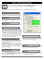
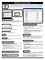
For each Gateway, the table displays the Gateway Description, assigned IP Address, the unique MAC Address of the Gateway (assigned at the factory), the
Gateway Firmware Version and the number of locks
assigned to the Gateway ("Assigned Locks").
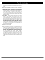
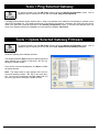
To confirm the status of the Gateway, simply click Tools,
View Gateway Status (see the "VIEW GATEWAY
STATUS " image).
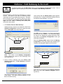
Using the Gateway Configuration Screen
Click the GW Confg button to open the Gateway Configuration screen (see the "GATEWAY CONFIGURATION SCREEN" image).
This management screen is the focal point of the DLWindows wireless system. With this screen you can add
new Gateways, search for locks, check system status,
and control the most common aspects of the system
hardware--with just a few clicks of the computer mouse.
VIEW GATEWAY STATUS
GATEWAY CONFIGURATION SCREEN
To start the process of adding Gateways into the Account, click the Discover New Gateways And Auto
Add to Account button.
18
Click the Update Status button to send a request
through the network for the condition of the Gateway,
and the Gateway's response populates the fields in this
screen. If an element of data is outdated or if a communication connection is broken, the relevant fields turn red
DL-WINDOWS™ for Trilogy Networx™ V4.0 USER'S GUIDE
Configuring DL-Windows for Wireless Lock Use (cont'd)
to warn of the possible malfunction. Green colored fields
indicate the attributes are within acceptable limits as set
by DL-Windows. To exit this screen, click Close. Note:
For new installations, some data may not yet exist, and
therefore several fields may be empty.
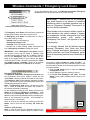
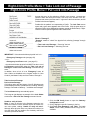
5. Discover physical locks on the Gateway
Each Networx™ lock is identified by a unique serial number assigned and programmed into the lock firmware at
the factory. To find installed locks, click the GW Confg
button to open the Gateway Configuration screen.
As shown in the "SELECTING A GATEWAY" image,
click to highlight and select the Gateway to which you
want to assign ("add") the installed locks. The Gateway
selected will transmit the discovery request radio signal
to the locks in the vicinity. Only those locks within range
that have not already been configured will respond.
DISCOVERED LOCK
6. Assign (add) discovered locks to the Gateway
In "DISCOVERED LOCK" example image, a popup
screen entitled "Discovered 1 Locks" appears, indicating the serial number of the lock, the signal strength and
the lock model.
To assign ("add") the discovered lock serial number(s) to
the selected Gateway, click the check box next to each
lock. To assign, click Use Selected Locks; to exit without assigning ("adding") any locks, click Cancel.
Click a row to highlight
and select a Gateway.
SELECTING A GATEWAY
The maximum search time allowed for each discovery
request is 1 minute. To minimize the search time, this
screen allows you to limit the search to a certain quantity
of installed locks. In addition, you can manually stop the
discovery process at any time by pressing the Esc key
on the keyboard. If you know the number of installed
locks to be discovered, select that number and the discovery process will stop the moment that number of
locks are found. If the number of locks selected exceeds
the actual number physically installed, the discovery
process will continue for either a maximum of 1 minute or
until the Esc key is pressed.
Example: If the number selected is 10, but in fact only 8
locks exist, the system may find all 8 locks, but will keep
searching for 10 until the one minute timeout duration
expires--or until the Esc key is pressed.
Click the Number of Locks to Discover pull-down list
and select a number of locks that you want to detect.
Click the Discover Locks On Selected Gateway button
to initiate the search.
The "DISCOVERED LOCK" image displays the results
when one lock was requested to be discovered and one
lock was found:
DL-WINDOWS™ for Trilogy Networx™ V4.0 USER'S GUIDE
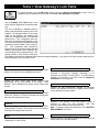
Note: When the Use Selected Locks button is clicked
(in the "Discovered Locks" popup), the Gateway sends
"configuration data" to the selected locks.
This
"configuration data" contains items (such as an internal
lock designation, a specific radio channel and security
data) that are all embedded in what is called a "Lock Config Table". This "configuration data" instructs the physical
lock(s) to communicate ONLY with that Gateway and prevents other Gateways from communicating with the
physical lock(s).
7. Link lock to a Profile.
In DL-Windows, the word "Link" is used to describe the
specific action of associating a "virtual lock" Profile to the
serial number of the physical lock installed on the door.
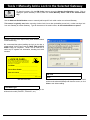
LINK LOCKS POPUP
After clicking Use Selected Locks, a Link Locks popup
appears, asking if you want to link your new locks now
(see LINK LOCKS POPUP). Click Yes to open the
Link/Unlink Lock Profiles screen or click No to cancel.
(see LINK / UNLINK PROFILES image).
19
Configuring DL-Windows for Wireless Lock Use (cont'd)
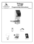
~ LOCK ID CARD ~
When installing lock, please fill in all information on
this card. This information will be used when adding network locks to DL Windows. Keep this card in
a safe place. Do not discard!
ALARM LOCK
LOCK MODEL _________________________________
FACTORY SERIAL NUMBER _______________________
INSTALLED LOCATION ___________________________
__________________________________________
OI353 10/08
SAVE THIS LOCK ID CARD
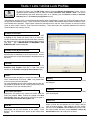
LINK / UNLINK PROFILES
The top half of the Link/Unlink Lock Profile(s) screen
contains two fields: "Available Lock Profiles" and
"Available Lock(s) By Serial Number".
The lock Profiles listed in the Available Lock Profiles
field are the same that were created in the "white box
area" of the main DL-Windows screen (the Account Tree
area). See the "LOCK PROFILES" image.
Click the Link Lock button to save this link association
within DL-Windows and to add the data to the table located in the bottom half of the Link/Unlink Lock Profile
(s) screen. If you link in error, click the Unlink Lock button, and the previously selected lock Profile and serial
number will return to their respective fields.
8. Send Programming to lock
After linking, a SEND PROGRAMMING TO LOCK NOW
popup automatically appears requesting if you wish to
send the lock Profiles to the physical lock(s):
Account Tree "white box"
area listing lock Profiles
SEND PROGRAMMING TO LOCK NOW POPUP
LOCK PROFILES
In the Available Lock Profiles field, click to select and
highlight the lock Profile. In the Available Lock(s) By
Serial Number field, click to select and highlight the corresponding lock serial number. We recommend that
when installing the lock on the door a yellow-colored
"Lock ID Card" (see the "SAVE THIS LOCK ID CARD"
image) be completed; the information on this card should
be used when performing this lock Profile linking process.
Click Yes to send the lock Profile in DL-Windows to the
onboard memory located inside each physical lock; click
No to cancel without communicating. If you click No,
you can always request the lock communication manually as outlined in the following step.
Click to highlight and
select the lock Profile
SELECT THE PROFILE
20
DL-WINDOWS™ for Trilogy Networx™ V4.0 USER'S GUIDE
Configuring DL-Windows for Wireless Lock Use (cont'd)
In the DL-Windows main screen, click to highlight the
lock Profile (see the "SELECT THE PROFILE " image).
Click the Comm button on the DL-Windows main
screen, then click Communicate with current Network
lock. The DL-Windows Network Lock Comm Screen
opens (see the "CLICK THE COMM BUTTON" image).
CLICK THE COMM BUTTON
This screen includes the name of the lock Profile in the
Lock Name field, and lists the specific elements of the
lock Profile to be transmitted. Note that checking the individual elements will take less time to transmit than
compared with checking "Send/Receive All". See the
"SELECT THE ELEMENTS TO BE SENT" image.
SELECT THE ELEMENTS TO BE SENT
For new installations, check "All" and click the Start
Communication button. The status bar at the bottom of
the window will indicate the communication progress.
When communication is complete, a popup will appear.
Click OK to close the popup, then click Close to close
the DL-Windows Network Lock Comm Screen.
Congratulations! Locks can now be put into use and
controlled wirelessly!
DL-WINDOWS™ for Trilogy Networx™ V4.0 USER'S GUIDE
21
Normal Tasks
DL-WINDOWS TASKS
Add a new lock Profile to an Account
Adding a new lock Profile is a common task in DlWindows, usually performed after creating a new Account. See page 15, step 1 ("Create a new Account")
and step 2 ("Create new virtual lock Profiles") for stepby-step instructions.
network adapter (Ethernet) built into the motherboard,
thus precluding the need for a separate Ethernet card.
Remember, the router or corporate Ethernet network is
connected to this Ethernet adapter with an Ethernet cable (RJ-45 plug).
Select Ethernet Adapter Click the pull-down menu to
select the IP address of the router or the IP address of
the existing corporate network on which the Gateway is
installed. Click OK to save.
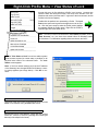
Delete a lock Profile from an Account
Open the DL-Windows main screen and find the Account Tree "white box" area listing lock Profiles. Simply
right-click the Profile and click Delete Lock Profile.
Note: Performing this action (clicking Delete Lock Profile) does not remove programming from the physical
lock because communication between DL-Windows and
the physical lock does not actually occur.
REPLACING HARDWARE
Replacing an existing Gateway
DL-Windows makes it easy to replace an existing Gateway device with a new one. Click the GW Confg button
to open the Gateway Configuration screen. Click to
highlight the Gateway in the list that you want to replace,
then click Actions, Replace Gateway with new one.
Be sure to remove power from the old Gateway. See
page 46 for the complete instructions.
Replacing an existing Router
Remove the existing router and install either a wired
or wireless router as described in its instructions.
For the connection between the computer and the
router, most laptops and some desktop computers contain a wireless network card (also called a "wireless network interface controller") to allow for wireless communication between your computer and a wireless router; if
your computer does not have a wireless network card,
you can usually connect the "non-wireless" network card
in your computer to the router using an RJ-45 Ethernet
cable.
For the connection from the router to the network,
the router is plugged into an Ethernet network source -usually either a modem or a wall jack. As shown in the
overview drawing on page 3, with "Large Networks" the
computer may be connected directly to the network
(usually just a wall jack) with an RJ-45 Ethernet cable.
Note: If the computer is connected directly to the network via a wall jack, the Gateway module may also be
connected directly to the network (for example, via another wall jack) at any location within the premises.
Click the GW Confg button to open the Gateway Configuration screen.
Click Tools, Select Network
Adapter. The Network Adapter Selection screen that
appears allows you to identify the Ethernet "network interface card" (NIC) you are using inside your computer
to communicate with the Gateway devices in your system. Some computers have a printed circuit board that
plugs into the motherboard, other computers have the
22
Replacing a physical lock
A physical lock is currently installed on a door, is fully
enrolled in the wireless system, but needs to be replaced with a new lock on the same door. Proceed as
follows:
Remove the old lock from the door, and install the new
lock as per the installation instructions WI1674. Make
note of the old and new lock serial numbers and have
these numbers available when you use DL-Windows.
In DL-Windows, click the GW Confg button to open the
Gateway Configuration screen. Click to highlight the
Gateway in the list to which the old lock was assigned,
then click Tools, Delete Locks by Serial Number.
The Delete Serial Number(s) screen opens. Check the
old lock's serial number and click the Delete Selected
Serial Number(s) button.
In the Gateway Configuration screen, click the Number
of Locks to Discover pull-down list and select a number
of locks that you want to detect; in this case, you can select "1" because you are only adding one new lock to the
system. Click the Discover Locks On Selected Gateway button to initiate the search.
A popup screen entitled "Discovered 1 Locks" will appear, indicating the serial number of the new lock, the
signal strength and the lock model of this newly installed
lock.
DL-WINDOWS™ for Trilogy Networx™ V4.0 USER'S GUIDE
Normal Tasks (cont'd)
Add the newly discovered lock serial number to the Gateway by clicking the check box next to the lock. Click the
Use Selected Locks button.
A Link Locks popup appears asking if you want to link
your new locks now (if the popup does not appear, click
Tools, Link / Unlink Lock Profiles. Click Yes to open
the Link / Unlink Lock Profiles screen.
In the "Available Lock Profiles" field, click the Profile
assigned to the lock that is being replaced, and click the
serial number of the newly installed lock in the
"Available Lock(s) By Serial Number" field.
After linking, a Send Profile to Lock Now popup automatically appears requesting if you wish to send the lock
Profiles to the physical lock (if the Send Profile to Lock
Now popup does not appear, go to the DL-Windows
main screen, click to highlight the lock Profile, then click
the Comm button and click Communicate with current
Network lock). The DL-Windows Network Lock
Comm Screen opens. Check "All" and click the Start
Communication button. When communication is complete, click the Close button.
I moved a lock from one door to another door,
but now the lock is out of range of its Gateway...what do I do?
This procedure can be described as simply deleting a
lock from its existing Gateway and re-discovering the
lock on another Gateway (within range of the lock's new
location).
If you need to install and add a new Gateway to the system, see "Adding a new Gateway to an existing system" further in this section.
First, delete the lock serial number from the Gateway to
which it is currently assigned. The yellow Lock ID Card
with the lock's serial number can be used for operations
of this kind. In the Gateway Configuration screen,
click Tools, Delete Locks by Serial Number. In the
Delete Serial Number(s) screen, check the serial number of the lock (the lock that was moved from one door
to another), then click the Delete Selected Serial Number(s) button.
Next, re-discover the lock serial number on another
Gateway. Click the GW Confg button to open the Gateway Configuration screen. Click to highlight a Gateway in the list that is closer to the lock's new location,
then click Actions, Discover Locks on Selected Gateway.
A popup screen entitled "Discovered 1 Locks" will appear, indicating the serial number of the re-discovered
lock, its signal strength and lock model.
Add the re-discovered lock serial number to the Gateway
by clicking the check box next to the lock. Click the Use
Selected Locks button.
DL-WINDOWS™ for Trilogy Networx™ V4.0 USER'S GUIDE
A Link Locks popup appears asking if you want to link
your new locks now (if the popup does not appear, click
Tools, Link / Unlink Lock Profiles. Click Yes to open
the Link / Unlink Lock Profiles screen.
In the "Available Lock Profiles" field, click the Profile
previously assigned to the lock that was re-discovered,
and click the serial number of this lock in the "Available
Lock(s) By Serial Number" field.
After linking, a Send Profile to Lock Now popup automatically appears requesting if you wish to send the lock
Profiles to the physical lock (if the Send Profile to Lock
Now popup does not appear, go to the DL-Windows
main screen, click to highlight the lock Profile, then click
the Comm button and click Communicate with current
Network lock). The DL-Windows Network Lock
Comm Screen opens. Check "All" and click the Start
Communication button. When communication is complete, click the Close button.
ADDING NEW HARDWARE
I just finished installing a new wireless lock
on a door. How do I add this new wireless
lock to my existing wireless system?
In theory, after installing the lock on the door, you would
want to use a Gateway in the system that is physically
closest to the new lock installation; the closer the Gateway, the better the radio signal between the lock and the
Gateway.
To ensure you select the "closest" Gateway, it is useful
to make note of all Gateway locations in the system.
But if you do not know which Gateway is closest, you
can discover the lock on each Gateway in turn, writing
down the reported signal strength to each Gateway,
then compare all signal strengths and select the Gateway with the strongest signal.
We recommend that when installing the lock on the door
a yellow-colored "Lock ID Card" be completed; the information on this card makes it easier when adding new
locks to the system.
For an existing Account, start by creating a new lock
Profile to which this new hardware will eventually be
linked, :
1. Create new virtual lock Profile
Open the DL-Windows. In the main screen, click the
Open button and the Account "white space" opens at
the left, listing all Accounts. Double-click the Account
name into which you want to add this new lock, displaying all lock Profiles in the Account. Notice the
Account name is highlighted in blue. Right-click the
Account name, opening the right-click menu, and
click New Lock(s) Profile. The New Lock Profile
dialog opens.
In the New Lock Profile dialog, type a description of
23
Normal Tasks (cont'd)
the new lock, which will typically be the name of the
room in the facility that the lock is securing. Select
the Lock Type to be programmed from the dropdown list (for example, the 6100 series), then click
the Number of Locks to Create pull-down menu and
select the number "1". When finished, click OK. After a few seconds, the new Profile is created and DLWindows automatically opens the Global Users
screen.
2. Discover the new physical lock with the Gateway
Each Networx™ lock is identified by a unique serial
number assigned and programmed into the lock firmware at the factory. To find installed locks, click the
GW Confg button to open the Gateway Configuration screen.
In the Gateway Configuration screen, click to highlight and select the Gateway to which you want to assign ("add") the new lock. The Gateway selected will
transmit the discovery request radio signal to the new
lock in the vicinity; if the new lock is within radio
range, the lock will respond.
The maximum search time allowed for each discovery request is 1 minute. To minimize the search time
waiting period, this screen allows you to limit the
search to a certain quantity of installed locks. In addition, you can manually stop the discovery process at
any time by pressing the Esc key on the keyboard.
Since you know the number of installed locks to be
discovered is "1", in the Number of Locks to Discover pull-down list, select "1" and the discovery
process will stop the moment "1" lock is found. (If the
number of locks selected exceeds the actual number
within radio range, the discovery process will continue for either a maximum of 1 minute or until the
Esc key is pressed).
Click the Discover Locks On Selected Gateway
button to initiate the search.
3. Assign (add) discovered locks to the Gateway
A popup screen entitled "Discovered 1 Locks" will
appear, indicating the serial number of the new lock,
its signal strength and lock model. If the serial number does not appear in this screen, click Close and
try again; if the serial number does not appear after
repeated tries, you may need to stop here and add a
new Gateway to the system (see "Add a new Gateway to an existing system" in this section)
In the "Discovered 1 Locks" popup screen, assign
("add") the discovered lock serial number(s) to the
selected Gateway by clicking the check box next to
the lock serial number. Click Use Selected Locks.
4. Link lock to a Profile.
A Link Locks popup appears, asking if you want to
link your new lock now to the Profile created in step
1. Click Yes to open the Link/Unlink Lock Profiles
screen.
The top half of the Link/Unlink Lock Profile(s)
24
screen contains two fields: "Available Lock Profiles" and "Available Lock(s) By Serial Number".
The lock Profile listed in the Available Lock Profiles
field is the same that was created in step 1; click to
select and highlight this lock Profile. In the Available
Lock(s) By Serial Number field, click to select and
highlight the corresponding lock serial number. Click
the Link Lock button to save this link association
within DL-Windows and to add the data to the table
located in the bottom half of the Link/Unlink Lock
Profile(s) screen.
5. Send Profile to lock.
After linking, a Send Profile to Lock Now popup
automatically appears requesting to send the lock
Profile to the physical lock. Click Yes to send the
lock Profile in DL-Windows to the onboard memory
located inside the new physical lock.
The DL-Windows Network Lock Comm Screen
opens.
Check "All" and click the Start Communication button. The status bar at the bottom of the window will
indicate the communication progress. When communication is complete, a popup will appear. Click OK
to close the popup, then click Close to close the DLWindows Network Lock Comm Screen.
Adding a new Gateway to an existing system.
Make note of the new Gateway's MAC address located
on a square sticker (look under the bar code). It has 12
digits, grouped in 6 pairs separated by dashes.
1. Install the new Gateway.
Use the installation instructions WI1674. Ceiling installations are typical.
2. Open DL-Windows.
In the main screen, click the Open button and the Account "white space" opens at the left, listing all Accounts. Double-click the Account name into which
you want to add this new Gateway.
3. Open the Gateway Configuration screen.
Click the GW Confg button to open the Gateway
Configuration screen.
4. Discover the new Gateway.
Click the Discover New Gateways And Auto Add
to Account button. A Discover New Gateways
popup appears; click Yes and DL-Windows searches
the network; when the new Gateway is found, it is
listed in the grid shown in the Gateway Configuration Screen. Verify the MAC address on the screen
matches the MAC address on the sticker inside the
Gateway.
Note that this "Discover New Gateways And Auto
Add to Account" button combines two actions--the
DL-WINDOWS™ for Trilogy Networx™ V4.0 USER'S GUIDE
Normal Tasks (cont'd)
"discovering the Gateway(s)" action, and the "adding
the Gateway(s) to the current Account" action.
Now that the new Gateway is added to the Account
in DL-Windows, you can use this new Gateway to
discover locks that have been (or will be) physically
installed on doors.
Resetting the Gateway
"Resetting" the Gateway clears all memory and ensures
that any residual voltage or test data existing from the
factory is cleared from the unit. Always reset the Gateway for new installations; you can also reset the Gateway anytime after the Gateway is powered. Two levels
of reset exist, a "Partial" reset and "Full" reset, as follows:
"Partial Reset" clears the Gateway's "Lock Config Table"; but if the Gateway was previously programmed for
wireless network communication, this reset leaves the
Gateway in this "wireless" condition. With power applied
to the Gateway, press and hold the "RESET" button and
the red light turns on continuously; continue to hold the
button and the red light will start to flicker. Release the
button and the red light will continue to flicker. The
Gateway is now "Partially Reset".
"Full Reset" returns the Gateway to its factory condition,
clearing the Gateway's "Lock Config Table" and resets
the network selections to its factory default "wired" condition. Continuing from the "Partial Reset" instructions
above, with the red light flickering without any buttons
being pressed...
...With the red light flickering, press and hold the
"RESET" button again and the red light turns on continuously...continue to hold the button and the red light will
start to flicker...continue to hold the button until the red
light turns on continuously...then release the button and
the red light turns off...after a few seconds the red light
will then start to flicker. The Gateway is now "Fully Reset".
DL-WINDOWS™ for Trilogy Networx™ V4.0 USER'S GUIDE
25
Menus
DL-Windows provides several menus throughout its screens. These menus can be accessed by right-clicking certain items,
or by simply clicking the menu bars located at the top of the application's window. Several of the menus are pictured below;
it may be helpful to create a "test" Account in DL-Windows and open these menus as you read this guide.
TOOLS MENU (PAGE 29)
WIRELESS COMMANDS MENU (PAGE 49)
DL-WINDOWS MAIN SCREEN, WIRELESS COMMANDS MENU
RIGHT-CLICK PROFILE MENU (PAGE 55)
GATEWAY CONFIGURATION SCREEN, TOOLS MENU
ACTIONS MENU (PAGE 40)
GATEWAY CONFIGURATION SCREEN, ACTIONS MENU
RIGHT-CLICK A PROFILE
26
DL-WINDOWS™ for Trilogy Networx™ V4.0 USER'S GUIDE
"GW Confg" Button
Click the GW Confg button to open the Gateway Configuration screen.
The Gateway Configuration screen allows you to seek out new Gateway devices and add them to a
specific Account; similarly, locks can be discovered and added to Gateways.
Menu Bar
Exit
Tools
View Gateway Status (see page 29)
View Gateway's Lock Table (see page 30)
Delete Locks by Serial Number (see page 31)
Link / Unlink Lock Profiles (see page 32)
Configure Network Settings (see page 33)
Ping Selected Gateway (see page 35)
Update Selected Gateway Firmware (see page 35)
Manually Add a Lock to the Selected Gateway (see page 36)
Send Lock Config Table to Selected Gateway (see page 37)
Send IP Table to Selected Gateway (see page 37)
Send IP Table to all Gateways (see page 37)
Import Assigned Lock From Gateway (see page 38)
Import Gateway and Assigned Locks (see page 38)
Select Network Adapter (see page 39)
Actions
Add Gateway to Account (see page 40)
Remove Gateway from Account (see page 41)
Locate All Locks on Gateway (see page 42)
Discover Locks on Selected Gateway (see page 43)
Discover New Gateways (see page 44)
Relocate Gateways (Displayed in red) (see page 45)
Replace Gateway with new one (see page 46)
Help
View Color Codes (see page 47)
Discover New Gateways and
Auto Add to Account
This button combines two activities--the "discovery" process
and the "add to an Account" process--in one button. Be sure
the Gateway is mounted, powered and connected to the router
(or the network); be sure to press the "RESET" button on the
PC board before the Gateway housing cover is secured (go to
page 25 and follow the "Resetting the Gateway" instructions
for a "Partial Reset"). In DL-Windows, click this button and the
Discover New Gateways popup appears, shown below. The
Gateways that are found on the network are then automatically
added to the current Account and listed in the Gateway
Configuration screen grid.
IP Address
Specifies the IP Address on the TCP/IP network currently
assigned to the Gateway. Required for communication.
MAC Address
A unique serial number burned into Gateway memory that
identifies that Gateway from all others. Inside the Gateway
housing, the MAC address is located on a square sticker
(look under the bar code) and has 12 digits, grouped in 6
pairs separated by dashes.
Firmware Version
Indicates the firmware source code edition currently residing
in the Gateway.
Assigned Locks
Indicates the total number of locks assigned to the selected
Gateway's database.
Number of Locks to Discover
Discover Locks on Selected Gateway
Description
Text name of the Gateway, as specified when the Gateway
was added to DL-Windows using the Add Gateway to
Account screen (click Actions, Add Gateway to Account).
DL-WINDOWS™ for Trilogy Networx™ V4.0 USER'S GUIDE
Use both to add locks to a Gateway. First, click to select an
existing Gateway in the grid to which you want to assign the
installed locks, then select the number of locks the system
will try to find in the Number of Locks to Discover pull27
down list. The Gateway selected will transmit the discovery
request radio signal to the locks in the vicinity. Only those locks
within range that have not already been configured will
respond.
Note: The maximum search time allowed for each discovery
request is 1 minute. To minimize the search waiting time, this
screen allows you to limit the search to a certain quantity of
installed locks. In addition, you can manually stop the
discovery process at any time by pressing the Esc key on the
keyboard. If you know the number of installed locks to be
discovered, select that number and the discovery process will
stop the moment that number of locks are found. If the number
of locks selected exceeds the actual number physically
installed, the discovery process will continue for either a
maximum of 1 minute or until the Esc key is pressed.
Example: If the number selected is 10, but in fact only 8 locks
exist, the system may find all 8 locks, but will keep searching for
10 until the one minute timeout duration expires--or until the
Esc key is pressed.
Click the Discover Locks On Selected Gateway button to
initiate the search.
Lock Configuration Error (Popup)
This popup appears after a failed attempt to assign
discovered physical locks to a Gateway.
As detailed previously, the Gateway Configuration screen
allows you to discover physical locks and assign them to a
specific Gateway (click the Discover Locks On Selected
Gateway button). The "Discovered Locks" popup appears
and lock(s) you wish to assign to the Gateway are selected.
When the Use Selected Locks button is clicked, the Gateway
sends "configuration data" to the selected locks. This
"configuration data" contains items (an internal lock
designation, a specific radio channel and security data) all
embedded in what is referred to as the "Lock Table". This
"configuration data" instructs the physical lock(s) to
communicate ONLY with that Gateway and prevents other
Gateways from communicating with the lock(s).
If after several attempts to communicate with the lock(s), the
Gateway still does not receive confirmation that this
"configuration data" was received from the selected lock(s)
successfully, this popup appears. In short, the Gateway was
unable to "configure" the selected physical locks, and thus
was unable to assign the selected physical locks to the
Gateway.
Lost Gateways (Popup)
The "Discovered Locks" popup displays the search results.
In the example shown above, the popup screen entitled
"Discovered 1 Locks" appears, indicating the serial number
of the lock(s), the signal strength and the lock model(s). Note:
The number displayed in the title bar will reflect the number of
discovered locks.
To assign the discovered physical lock(s) to the selected
Gateway, click the check box next to each lock and click Use
Selected Locks; to exit without assigning, click Cancel.
Link Locks (Popup)
After the discovered physical lock(s) are assigned to the
selected Gateway and Use Selected Locks is clicked, the
system requests if you wish to "Link" the discovered physical
locks to a "virtual lock" Profile. Click Yes to proceed or click No
to exit without linking.
28
This popup appears if the connection between DL-Windows
and the Gateway is lost or is not working properly. Click Yes
to attempt to reconnect to the specified Gateway.
Lock already exists (Popup)
This popup appears if you attempt to use a selected lock in
the "Discovered Locks" popup that already exists in the Lock
Table of the selected Gateway. Click OK to attempt to
reconfigure by re-sending the "Lock Config Table" to the
selected Gateway.
DL-WINDOWS™ for Trilogy Networx™ V4.0 USER'S GUIDE
Tools > View Gateway Status
To open this screen, click the GW Confg button to open the Gateway Configuration screen. Click to
highlight a specific Gateway in the list, then click Tools, View Gateway Status.
The Gateway Status screen displays the operational status of the selected Gateway as of the last update.
Gateway Description
Text name of the Gateway, as specified when the Gateway
was added to DL-Windows using the Add Gateway to
Account screen (click Actions, Add Gateway to Account).
Gateway IP Address
Specifies the static IP Address on the TCP/IP network
currently assigned to the Gateway.
Required for
communication.
Gateway Firmware Ver
Indicates the firmware source code edition currently residing
in the Gateway.
Firmware Update
Indicates the result of the last Gateway firmware upgrade
process. "Good" signifies that the last firmware upgrade was
completed without errors. If "Bad", upgrade the firmware as
follows: Click the GW Confg button to open the Gateway
Configuration screen; click to highlight a Gateway in the
list, then click Tools, Update Selected Gateway Firmware.
The system checked the integrity of the firmware, burned it
into the Gateway memory, rebooted the Gateway and
verified the Gateway is functioning properly.
Security Code
The Account Security Code is first specified when the
Account is created in DL-Windows; this Security Code is
then copied to the Gateway firmware when the Gateway is
first added to the Account.
This field indicates the status of the Security Code by
comparing the Security Code in the Gateway with the
Security Code in DL-Windows; if Codes are not identical, the
field indicates "Mismatch", thus disabling DL-Windows-toGateway communications.
Gateway Status
An overall state or condition of the Gateway. Displays either
"Ready" to indicate a normal condition; "Lock Down" if an
Emergency Lock Down Command was sent; and "Passage"
if an Emergency Passage Command was sent.
Last Updated
Indicates the date and time the current Gateway Status
screen was changed with new elements of data.
Lock Communication Error
Indicates if locks associated with the selected Gateway fail
to communicate with that Gateway.
If an error is indicated, open the Gateway Configuration
screen, click Tools, View Gateway's Lock Table to
determine which lock generated the error.
DL-WINDOWS™ for Trilogy Networx™ V4.0 USER'S GUIDE
Update Status
Click to delete all existing data elements appearing in this
screen and request new data be generated based on the
current condition of the Gateway.
29
Tools > View Gateway's Lock Table
To open this screen, click the GW Confg button to open the Gateway Configuration screen. Click to
highlight a specific Gateway in the list, then click Tools, View Gateway's Lock Table.
Use the Gateway Lock Table screen to see
which locks are assigned to the selected Gateway.
The act of "configuring" a Gateway means to
assign (add) discovered physical locks to the
Gateway. DL-Windows sends a "Lock Config
Table" to that Gateway; the Gateway then
sends this "configuration data" to the selected
physical locks. This "configuration data" contains items--an internal lock designation, a specific radio channel and security data--that are all
embedded in what is called a "Lock Config Table". This "configuration data" instructs the
physical lock(s) to communicate ONLY with that
Gateway and prevents other Gateways from
communicating with the physical lock(s). Configuring ensures a fixed wireless communication channel exists between selected physical locks and a selected Gateway. If you want to see which locks are assigned to the
selected Gateway, this is the option to use.
Lock Name
Text name of the lock Profile, as specified when the lock was
added to DL-Windows using the New Lock screen.
Serial No.
Displays the lock's unique serial number assigned and
programmed into the lock firmware at the factory. Each
Networx™ lock is identified in the system by this unique serial
number.
Lock Model
Specifies the style of Trilogy Networx™ series door lock, such as
"PDL6100", "DL6100" or "PL6100" (including other model types
that may be developed in the future).
Firm. Ver
Identifies the specific edition or release of the current lock's
Trilogy Networx™ firmware. The firmware is stored in memory
chips that are located inside each lock.
Status
Indicates whether the physical lock is currently "assigned" or
"unassigned" to a lock Profile.
30
Lock Status
Indicates whether the physical lock is currently locked,
unlocked, in Emergency Passage ("Passage") or In
Emergency Lock Down ("In Lock Down"). To set Emergency
Passage or Emergency Lock Down, see the Emergency
Commands menu on page 49.
Signal
Indicates the radio transmission strength, as measured
between the Gateway and the lock; a higher number (closer
to 100) indicates a stronger signal.
Battery
Indicates if the strength of the total battery voltage is
sufficient to power the lock firmware, radio and
electromechanical parts located inside the lock.
Note: For battery replacement instructions, see "BATTERY
REPLACEMENT" in WI1674.
Update Database (button)
Click this button to command DL-Windows to re-send the "Lock
Config Table" to the selected Gateway.
DL-WINDOWS™ for Trilogy Networx™ V4.0 USER'S GUIDE
Tools > Delete Locks by Serial Number
To open this screen, click the GW Confg button to open the Gateway Configuration screen. Click to
highlight a specific Gateway in the list, then click Tools, Delete Locks by Serial Number.
Use the Delete Serial Number(s) screen to remove selected lock serial numbers from a Gateway.
Note: All locks on all Gateways in the Account are listed in this screen; multiple locks can be removed from multiple Gateways. Check all check boxes to select the lock(s) to be removed.
Delete Serial Number(s) Main Screen
This screen lists all physical locks and their assigned
Gateways in the Account.
Each physical lock is represented by its unique serial
number; each Gateway is represented by its name and IP
address.
Check all check boxes to select the locks to be removed,
then click the Delete Selected Serial Number(s) button to
delete the selected locks (or click the Close button to cancel
without deleting).
Before removing the lock serial numbers, a confirmation
Remove Serial Numbers popup appears; click OK to
permanently delete the physical lock serial numbers
selected.
Delete Lock Popup
If the Gateway is unable to communicate with the physical
lock, an Delete Lock popup appears, informing you that
although DL-Windows is currently unable to communicate
with the Gateway(s), the lock serial number may still be
removed from the DL-Windows database. To delete the
lock, click Yes, to exit without deleting, click No.
Remove Serial Numbers Popup
If you forgot to check any locks and clicked the Delete
Selected Serial Number(s) button, the following popup
appears:
Click OK and try again.
DL-WINDOWS™ for Trilogy Networx™ V4.0 USER'S GUIDE
31
Tools > Link / Unlink Lock Profiles
To open this screen, click the GW Confg button to open the Gateway Configuration screen. Click to
highlight a specific Gateway in the list, then click Tools, Link/Unlink Lock Profiles. Note: This screen
will automatically open after discovering locks on a Gateway (see the Discover Locks on Selected
Gateway button in the Gateway Configuration screen).
In DL-Windows, the word "Link" is used to describe the specific action of associating a "virtual lock" Profile to the serial number of
the physical lock installed on a door. These "virtual lock" Profiles are created in DL-Windows and are used to simulate the "real"
locks installed in the premises. These Profiles contain the instructions that a real lock uses to perform its various functions
(such as User Codes, Features, Time Zones and Schedules). These instructions are essentially database files that are
stored inside the lock memory circuitry.
Available Lock Profiles
Displays existing lock Profiles in the current Account. Click
to highlight a lock Profile you wish to link to a "real" lock.
The lock Profiles listed here are the same that were created in
the "white box area" of the main DL-Windows screen "Account
Tree area". See "CONFIGURING DL-WINDOWS FOR
WIRELESS USE" earlier in this guide.
Available Lock(s) By Serial Number
Displays the lock serial numbers of all "real" locks
discovered by all Gateways in the current Account. All lock
serial numbers are unique and assigned to the physical lock at
the factory.
Link Lock
Click this button to link the highlighted Profile (in the
Available Lock Profiles field) with a "real" lock serial
number (in the Available Lock(s) By Serial Number field).
LockID
Displays a number assigned to a virtual lock when the virtual
lock is created within an Account. Note: Only linked locks
in the current Account are listed here.
For more information about LockID numbers and how they are
used within DL-Windows, see the "LockID" glossary entry in the
DL-Windows V3.6.0 User's Guide (OI237).
Gateway
Displays the name of the Gateway to which the linked locks
are assigned.
IP Address
Lock Profile Description
Displays the text name of the virtual lock Profile when the
Profile was created. Note: Profiles are created in the New
Lock Profile dialog; the text name of the Profile is typed in
the Enter New Lock Profile Description field.
Serial No.
Displays the lock's unique serial number assigned and
programmed into the lock firmware at the factory. Each
Networx™ lock is identified in the system by this unique serial
number.
32
Displays the IP address of the Gateway to which the linked
locks are assigned.
Unlink Lock
First select a linked lock listed in the grid, then click this
button to break the link between the "lock Profile" and the
"real" lock serial number. After unlinking, the "lock Profile"
will return to the Available Lock Profiles field and the "real"
lock serial number will return to the Available Lock(s) By
Serial Number field, both ready to be re-linked.
DL-WINDOWS™ for Trilogy Networx™ V4.0 USER'S GUIDE
Tools > Configure Network Settings
To open this screen, click the GW Confg button to open the Gateway Configuration screen. Click to
highlight a specific Gateway in the list, then click Tools, Configure Network Settings.
The Network Configuration screen displays the various networking attributes required for the selected Gateway to work
correctly within the current wireless network. See your network administrator for more information if needed.
Note: For wireless security, because the communications between the network/router and the Gateway conform to the AES
(Advanced Encryption Standard), we recommend leaving the system unsecure, but to use MAC address filtering within the router
software (if your router supports MAC Address filtering). Using this kind of security is easier to setup and more secure than using
the security protocols (encryption methods) shown within this screen.
Use DHCP
Use DHCP (Dynamic Host Configuration Protocol) is enabled
by default. When checked and Save Configuration is
clicked, DL-Windows allows the selected Gateway to accept
the dynamic assignment of an IP address by the TCP/IP
network. Check Use DHCP to remove the need to manually
assign a static (fixed) IP address to the Gateway (note that
Emergency Commands will NOT work). Uncheck Use DHCP
to allow the manual assignment of a static IP address to the
selected Gateway (a warning popup appears [shown on page
8] warning that the Gateway may be unreachable until it is
installed on the correct network or is manually defaulted).
See your network administrator for additional information.
DHCP Name
To aid in locating the Gateway on the network, specify a name
to describe the domain name (host name) of the corresponding
IP Address assigned to the selected Gateway. The DHCP
name entered here will be used for the DNS configuration.
Wireless Mode
Configures the selected Gateway for either wireless or wired
communication with the computer network. Select either Wired
Only or Wireless Only from this pull-down menu. If Wireless
Only is selected, the Wireless Network fields located in this
screen become active and available for selection.
IP Address
If the Use DHCP (see above) is unchecked, this field allows
the IP address to be manually assigned to the selected
Gateway.
Subnet Mask
To improve performance, network administrators determine
how best to divide their network. Create more hosts and
fewer subnets or more subnets and fewer hosts? The IP
protocol makes use of a Subnet Mask to more efficiently
route packets to their correct network destinations. When a
Gateway receives a data packet, the Subnet Mask indicates
how many bits of the packet's destination address are to be
used for routing and which bits are to be "masked" (ignored).
Use DHCP (see above) must be unchecked before data can
be entered into this field. This information must be obtained
from your network administrator.
Default Gateway
This field is the IP address of the physical device, such as a
router, for the current subnet to which you want to be
connected. This field is not to be confused with the IP
address of the Alarm Lock Gateway device installed in the
system. Use DHCP (see above) must be unchecked before
typing the IP address. This information must be obtained
from your network administrator.
Network Name (SSID)
The Gateway module acts as an interface between a computer
network and the Networx™ wireless locks. Of the two Gateway
models available ("Wired" or "Wireless/Wired"), the "Wireless/
Wired" Gateway model supports connection to a network using
the 802.11 standard. This field allows you to specify the SSID
(Service Set IDentifier) name assigned to the wireless Wi-Fi
(802.11) network. All "Wireless/Wired" Gateway models in a
system must use this name to allow for network
communication. Note: This field is case-sensitive and can
be up to 32 bytes in length. In addition, the Wireless Mode
pull-down menu in this screen must be set to Wireless Only
for this field to become active.
Network Type
Click this pull-down menu to select the network
communication mode. With "Infrastructure" selected, the
Gateways communicate to a wired LAN via access points.
With "Ad Hoc" selected, the Gateways can communicate
directly in a peer-to-peer fashion. Contact your network
administrator for more information.
( c o nt in u ed )
DL-WINDOWS™ for Trilogy Networx™ V4.0 USER'S GUIDE
33
Channel Number
Click this pull-down menu to manually specify the number (111) of the carrier frequency (subchannel pathway) between
the selected Gateway and the wireless Wi-Fi (802.11)
network. Contact your network administrator for more
information.
Encryption
The reversible transformation of data from its original format into a concealed format as a process for securing its
accessibility, authenticity and integrity. Encryption uses an
encryption algorithm (sequence) and one or more encryption keys (numeric codes).
When WEP Security Type is selected, the options for the
selected Gateway are:
Security Type
●
64 bits: Although the 64-bit WEP data encryption
method uses a five-character key size (forty bits or five
bytes) for symmetric encryption, plus an additional 24
factory-set bits, this method represents a relatively low
level of security.
●
128 bits: Stronger than 64-bit WEP, 128-bit WEP uses
a string of 26 hexadecimal characters (0-9 and A-F),
each representing four bits of the key.
For the selected Gateway, click the pull-down menu to
specify the 802.11 security protocol (encryption method) to
be used when the selected Gateway is connected to the
wireless network. The selections are as follows:
WEP (Wired Equivalent Privacy) The WEP encryption
method was designed to provide wireless networks with the
"equivalent" security available in traditional wired "landline"
networks.
WPA (Wi-Fi Protected Access) A security protocol from the
Wi-Fi alliance for 802.11 wireless networks. It uses the
Temporal Key Integrity Protocol (TKIP) to provide stronger
encryption than the earlier WEP (Wired Equivalent Privacy)
method. Derived from, and a subset of, the IEEE 802.11i
security standard, WPA includes 802.1x authentication.
WPA2 Supports additional security features of the IEEE
802.11i standard that are not already included in the WPA
security protocol.
Note: For each Security Type selected, different choices
appear for the other fields in the Wireless Network Security
area of this screen.
When WPA Security Type is selected, the option for the
selected Gateway is:
●
TKIP: (Temporal Key Integrity Protocol), a security protocol algorithm that compliments WEP encryption with
increased security measures such as extended key
lengths and data integrity checks.
When WPA2 Security Type is selected, the options for the
selected Gateway are:
●
CCMP: (Counter Mode with Cipher Block Chaining
Message Authentication Code Protocol) improves upon
both WEP and TKIP. CCMP is a required option for Robust Security Network (RSN) compliant networks.
●
TKIP: See above.
Key Type
For the selected Gateway, click the pull-down menu to
specify the 802.11 authentication protocol to be used when
the selected Gateway is connected to the wireless network.
A "key" is a numeric code used to encrypt data, and is used
to secure the data traffic between the DL-Windows, the
Gateways and the locks. The key "type" can be a password, a passphrase, or a hexadecimal string like '45D3
E454 3523 EDC2'. To ease encryption key entry, a password or passphrase can be entered instead of the cryptic
hexadecimal characters.
When WEP Security Type is selected, the options for the
selected Gateway are:
Key
Authentication
Verifies the origin of transmitted data.
●
Open/None: Requires no Authentication for the data
transmissions between the selected Gateway and DLWindows.
●
Shared: Requires a shared symmetric numeric code
(encryption "key") for all data transmissions between DLWindows and the Gateway.
When WPA or WPA2 Security Type is selected, the option
is:
●
34
Pre-Shared Key (PSK): Requires a numeric code
(encryption "key") previously shared between DLWindows and the Gateway using a secure channel for
all data transmissions.
Retype Key
Type your key in the Key field, and re-type in the Retype
Key field to confirm it.
Get Network Configuration from Gateway
Retrieves the current settings of the Gateway and displays
these settings in this screen.
Save Configuration
Click Save Configuration to save your settings and close
the screen, or click Close to exit without saving.
DL-WINDOWS™ for Trilogy Networx™ V4.0 USER'S GUIDE
Tools > Ping Selected Gateway
To open this screen, click the GW Confg button to open the Gateway Configuration screen. Click to
highlight a specific Gateway in the list, then click Tools, Ping Selected Gateway.
The Ping (Packet INternet Groper) network utility is used to test whether the IP address of the Gateway is available on the
network for immediate use. Ping sends a packet out on the network and waits for a response; the result of the ping is indicated in the status bar located at the bottom of the Gateway Configuration screen. A successful test displays the IP address of the Gateway with the word "Found"; an unsuccessful test displays "Not Found".
Tools > Update Selected Gateway Firmware
To open this screen, click the GW Confg button to open the Gateway Configuration screen. Click to
highlight a specific Gateway in the list, then click Tools, Update Selected Gateway Firmware.
Allows the updating of the Gateway firmware.
The standard Windows Open dialog box appears (shown at
right), allowing you to browse for the binary ".bin" file containing the firmware update.
Once the file is selected (highlighted), click Open to initiate
the update process.
Note: The image shown at right displays both lock firmware and Gateway firmware ".bin" files in the same directory. Be sure the file selected in the File name field is of
the correct type before initiating the update process.
DL-WINDOWS™ for Trilogy Networx™ V4.0 USER'S GUIDE
35
Tools > Manually Add a Lock to the Selected Gateway
To open this screen, click the GW Confg button to open the Gateway Configuration screen. Click to
highlight a specific Gateway in the list, then click Tools, Manually Add a Lock to the Selected Gateway.
Use the Add Lock Serial Number screen to manually add a specific lock serial number to a selected Gateway.
This screen is typically used when removing a broken lock from a door (and adding a new lock), or when moving a lock
from one Gateway to another Gateway. Type all characters of the serial number, do not include dashes or spaces.
Lock Serial Number
Carefully type the lock's unique factory serial number located
on the lock housing.
We recommend that when installing the lock on the door a
yellow-colored "Lock ID Card" (see the "SAVE THIS LOCK ID
CARD" image) be completed. These Lock ID Cards are a
useful way to organize lock information, including lock serial
numbers.
~ LOCK ID CARD ~
When installing lock, please fill in all information on
this card. This information will be used when adding network locks to DL Windows. Keep this card in
a safe place. Do not discard!
ALARM LOCK
LOCK MODEL _________________________________
FACTORY SERIAL NUMBER _______________________
INSTALLED LOCATION ___________________________
__________________________________________
OI353 10/08
SAVE THIS LOCK ID CARD
Add Lock
Close
Click Add Lock to assign ("add") the specified lock serial
number to the selected Gateway and close the screen, or click
Close to exit without adding.
Lock Model Type
Click the Lock Model Type pull-down and highlight the
wireless lock model ("DL6100", "PDL6100", etc.).
36
DL-WINDOWS™ for Trilogy Networx™ V4.0 USER'S GUIDE
Tools > Send Lock Config Table to Selected Gateway
To open this screen, click the GW Confg button to open the Gateway Configuration screen. Click to
highlight a specific Gateway in the list, then click Tools, Send Lock Config Table to Selected Gateway.
In DL-Windows, the word "Configure" has a specific meaning--to "Configure" is to "assign" discovered physical locks to a
Gateway, thus ensuring a fixed wireless communication channel exists between selected physical locks and a selected
Gateway.
How does the system "Configure"?
The Gateway sends "configuration data" in the form of a "Lock Configuration Table" to the selected locks. This "configuration
data" contains items--an internal lock designation, a specific radio channel and security data--that are all embedded in the
"Lock Configuration Table". This "configuration data" instructs the physical lock(s) to communicate ONLY with that Gateway
and prevents other Gateways from communicating with the physical lock(s).
In short, the Gateway tries to "configure" the selected physical locks, assigning the selected physical locks to the Gateway.
Tools > Send IP Table to Selected Gateway
Tools > Send IP Table to all Gateways
To open this screen, click the GW Confg button to open the Gateway Configuration screen. Click to
highlight a specific Gateway in the list, then click Tools, Send IP Table to Selected Gateway. You can
also click Send IP Table to all Gateways to send the IP Table to ALL Gateways without the need to highlight a specific Gateway.
For Accounts with multiple Gateways that are programmed to respond to Emergency Commands (see pages 51-53) these menu
items are a preliminary step to ensure that selected Gateways are able to communicate with each other without the need for DLWindows to be connected to the system. To allow this communication between Gateways, each Gateway in the Account must
possess the static IP Address of every other Gateway in the Account. Use these DL-Windows menu items to manually distribute
the static IP addresses of each Gateway (in the form of a DL-Windows "IP Table") to either a "selected" Gateway or to "all" other
Gateways in the Account. The diagram at left illustrates how Emergency Commands are distributed: Pressing an Emergency
code at a lock keypad (step 1) causes the keypad to send the Emergency Command to its assigned Gateway (named "Gateway A"
in step 2). This "Gateway A" sends the Emergency Command to all locks assigned to "Gateway A" (step 3) and also "Gateway A"
sends the same Emergency Command to each Gateway IP address listed in its "IP Table" via the Router (step 4). With each
Gateway receiving the Emergency Command from "Gateway A" (step 5), each of these Gateways then sends this Emergency
Command to each of its assigned locks (step 6). Notice that DL-Windows
is not needed to disseminate Emergency Commands and therefore not
shown in this diagram.
)))
4
Router
)))
)))
)) )
))
))
))
)))
))
)
GATEWAY
B
))
GATEWAY
C
))
))
)
Important: When adding a new Gateway to an Account, be sure use the
Send IP Table to all Gateways Command to ensure all existing Gateways
in the Account have the IP Address of the new Gateway. All Emergency
Commands MUST be tested weekly (or daily if necessary) to ensure their
correct operation. Note: These menu items are only used when more
than one Gateway exists in a system.
GATEWAY
D
))
))
5
))
)
3
6
))))
)))
)))
GATEWAY
A
))
)))
))))
2
)))
))
))
1
HOW EMERGENCY COMMANDS ARE DISSEMINATED TO ALL
GATEWAYS AND LOCKS IN AN ACCOUNT
DL-WINDOWS™ for Trilogy Networx™ V4.0 USER'S GUIDE
● For systems with only one Gateway, that Gateway can operate with
either a static IP address or the dynamic assignment of an IP address
by the TCP/IP network (if you wish, "Use DHCP" can be checked in
the Network Configuration screen; see "Tools > Configure
Network Settings" on page 33). Since only one Gateway exists in
the system, that Gateway obviously does not need to maintain the IP
addresses of other non-existent Gateways. Therefore, systems with
only one Gateway do not require the use of these menu items.
● For systems with more than one Gateway, static IP addresses
(listed within the DL-Windows "IP Table") MUST be distributed and
assigned to all Gateways within the system. After all locks are
installed and working, and static IP addresses are assigned to each of
the Gateways, click Tools > Send IP Table to Selected Gateway (or
click Tools > Send IP Table to all Gateways) to distribute these
Gateway IP addresses to each Gateway in the system.
37
Tools > Import Assigned Lock From Gateway
Tools > Import Gateway and Assigned Locks
To open this screen, click the GW Confg button to open the Gateway Configuration screen. Click to
highlight a specific Gateway in the list, then click:
●
Tools, Import Assigned Lock From Gateway
When the Account information stored in DL-Windows is lost
(such as with a stolen laptop)--AND--the DL-Windows
backup files are either non-existent, inadequate or lost, the
above "Import" options can be used to rebuild an existing
wireless system using the data stored inside the onboard
memory of the installed Gateway device(s).
Click OK to close the popup, then on the DL-Windows
main screen, click Tools, Set Security Password, and
the Set Security Password dialog appears:
Although these two options might never be used, their existence highlights the vital importance of maintaining safe, secure and up-to-date DL-Windows backup files. The short
period of time it takes to back up your files may save
HOURS of tedium trying to re-create and re-build your system.
Backup your Accounts
On the DL-Windows main screen, click Tools, Backup Accounts, and the Backup Accounts dialog opens, allowing
you to select where DL-Windows will copy all Account database files; click to select an existing "Backup" folder (or
check the Create New Folder checkbox to generate and
name a new folder). To restore your data, simply copy and
paste the backup files into C:\DL-Windows.
SET SECURITY PASSWORD DIALOG
4.
BACKUP ACCOUNTS SCREEN
Restoring Data without Backups
If no backups were made for an existing wireless system
and the Account information stored in DL-Windows is lost,
the basic procedure is as follows:
1. Re-install the DL-Windows software.
2. Re-create the Account and all assigned lock Profiles.
In addition, the Global Users screen will need to be repopulated with all Users.
3. Click the GW Confg button, and a popup appears:
38
5.
6.
7.
8.
9.
In the Set Security Password dialog, enter the original
"Security Password" used in the original Account, then
click OK to save.
Important: "Security Passwords" are used to differentiate between separate wireless Accounts. Do NOT share
passwords between Accounts, otherwise the radio signals of separate Accounts can become intermixed. Be
sure you record--in writing--all Account passwords in a
safe location; once set, passwords are NOT retrievable
from DL-Windows!
Click the GW Confg button to open the Gateway Configuration screen.
Click Actions, Discover New Gateways. The Gateway(s) appear in the Gateway Configuration screen
in green colored text.
Click to highlight a specific green-colored Gateway in
the list.
Click Tools, Import Gateway and Assigned Locks to
bring in the Gateway settings and all lock serial number data assigned to that Gateway.
In the Gateway Configuration screen, click Tools,
Link / Unlink Lock Profiles.
In the Link / Unlink Lock Profiles screen, the lock serial numbers will be listed in the Available Lock(s) By
Serial Number field, available to be re-linked. After
linking, a Send Profile to Lock Now popup automatically
appears requesting if you wish to send the lock Profiles to
the physical lock(s).
DL-WINDOWS™ for Trilogy Networx™ V4.0 USER'S GUIDE
Tools > Select Network Adapter
To open this screen, click the GW Confg button to open the Gateway Configuration screen. Click
Tools, Select Network Adapter.
The Network Adapter Selection screen allows you to identify the Ethernet "network interface card" (NIC) you are using inside your computer to communicate with the Gateway devices in your system. Some computers have a printed circuit
board that plugs into the motherboard, other computers have the network adapter (Ethernet) built into the motherboard, thus
precluding the need for a separate Ethernet card. Remember, the router or corporate Ethernet network is connected to this
Ethernet adapter with an Ethernet cable (RJ-45 plug).
Select Ethernet Adapter
Click the pull-down menu to select the network card used in
the computer.
Click OK to save the selection or Cancel to exit without
saving. Note: Clicking OK in this dialog saves the selection
only for the duration of the current DL-Windows session.
Quitting and restarting DL-Windows may require re-opening
this dialog and re-selecting the network adapter.
DL-WINDOWS™ for Trilogy Networx™ V4.0 USER'S GUIDE
39
Actions > Add Gateway to Account
To open this screen, click the GW Confg button to open the Gateway Configuration screen. Click to
highlight a specific Gateway in the list, then click Actions, Add Gateway to Account.
Select this option to add discovered Gateways to a current
Account. This option is only used for Gateways already
"discovered" but not yet assigned to an Account. Therefore,
before using this option, you must first "discover" the Gateway on the network with the Actions, Discover New Gateways menu item. Note: If Gateways have already been
discovered, skip to step 2.
Upon clicking Yes, the Gateway Name popup appears,
prompting you to change the default Gateway Description name of "New Gateway", if you wish.
1. Click Actions, Discover New Gateways.
Gateways that are found on the network are listed in the
Gateway Configuration screen grid--in green text--each
with the Description name "New Gateway".
Click OK to save, or Cancel to exit without changing the
default name of the Gateway. You can always change
the name of the Gateway by double-clicking the Gateway listed in the Gateway Configuration screen grid
(this popup will appear).
(Green text)
Note: The bottom of the Gateway Configuration
screen indicates the number of new Gateway(s) found
(see image above).
When the Gateway Name popup closes, the Gateway
Configuration screen grid remains open, displaying the
Gateway, now assigned ("added") to the Account.
(Blue text)
2. Click to select a Gateway, then click Actions, Add
Gateway to Account. The Save Gateway confirmation
popup appears:
Notice the text at the bottom of the Gateway Configuration screen now reads "Gateway Assigned" (see image above).
The popup references the Gateway IP address and its
serial number. Click Yes to add the Gateway, or click
No to exit without saving.
40
DL-WINDOWS™ for Trilogy Networx™ V4.0 USER'S GUIDE
Actions > Remove Gateway from Account
To open this screen, click the GW Confg button to open the Gateway Configuration screen. Click to
highlight a specific Gateway in the list, then click Actions, Remove Gateway from Account.
Before the Gateway can be removed from the Account, any
locks already assigned to the selected Gateway must first
be deleted ("un-assigned") from that Gateway.
Note: If all locks have already been deleted from the Gateway, skip to step 2.
1. First remove any assigned locks from the Gateway.
Click Tools, Delete Locks by Serial Number.
Click Yes to delete or No to exit without deleting the
Gateway.
Note: If you forget to check any check boxes, the following popup will appear to remind you:
Click OK and try again.
The Delete Serial Number(s) screen lists all locks and
their assigned Gateways in the Account.
Each lock is represented by its unique serial number;
each Gateway is represented by its name and IP address.
Check all check boxes to select the locks to be removed
from the Gateway you wish to remove from the Account.
Click the Delete Selected Serial Number(s) button to
delete the selected locks.
IMPORTANT: Double-check each serial number selected to be sure they are the locks assigned to the
Gateway(s) you wish to remove.
2. With all locks removed from the Gateway, click Actions,
Remove Gateway from Account. The Remove Gateway popup appears, indicating the IP address and serial
number of the Gateway to be removed.
DL-WINDOWS™ for Trilogy Networx™ V4.0 USER'S GUIDE
41
Actions > Locate All Locks on Gateway
To open this screen, click the GW Confg button to open the Gateway Configuration screen. Click to
highlight a specific Gateway in the list, then click Actions, Locate All Locks on Gateway.
This option requests all wireless locks assigned to the selected Gateway to beep and flash their red LED's; used when you
wish to find the physical locks or to confirm the wireless connection is operational. Click this selection and the Select Locate
Time popup appears:
Select Locate Time in Seconds
Click the pull-down menu to select the Locate Time in
seconds. Up to 255 seconds (4 minutes 15 seconds) can be
selected; default duration is 30 seconds.
Click OK, and all wireless locks assigned to the selected
Gateway will beep and flash their red LED's for the selected
duration.
Click Cancel to exit without requesting this action.
42
DL-WINDOWS™ for Trilogy Networx™ V4.0 USER'S GUIDE
Actions > Discover Locks on Selected Gateway
To open this screen, click the GW Confg button to open the Gateway Configuration screen. Click to
highlight a specific Gateway in the list, then click Actions, Discover Locks on Selected Gateway.
This option is identical in operation to the Discover Locks on Selected Gateway button found in the Gateway Configuration screen.
Identical in operation
Discover Locks on Selected Gateway
First, in the Gateway Configuration screen, click to select
an existing Gateway in the grid to which you want to assign
the installed locks, then select the number of locks the system will try to find in the Number of Locks to Discover
pull-down list. The Gateway selected will transmit the discovery request radio signal to the locks in the vicinity. Only those
locks within range that have not already been configured (i.e.
assigned to Gateways) will respond.
Note: The maximum search time allowed for each discovery
request is 1 minute. To minimize the search waiting time, this
screen allows you to limit the search to a certain quantity of
installed locks. In addition, you can manually stop the discovery process at any time by pressing the Esc key on your computer keyboard. If you know the number of installed locks to
be discovered, select that number and the discovery process
will stop the moment that number of locks are found. If the
number of locks selected exceeds the actual number physically installed, the discovery process will continue for either a
maximum of 1 minute or until the Esc key is pressed.
of the lock(s), the signal strength and the lock model(s). Note:
The number displayed in the title bar will reflect the number of
discovered locks.
To assign the discovered physical lock(s) to the selected
Gateway, click the check box next to each lock and click Use
Selected Locks; to exit without assigning, click Cancel.
Example: If the number selected is 10, but in fact only 8
locks exist, the system may find all 8 locks, but will keep
searching for 10 until the one minute timeout duration expires-or until the Esc key is pressed.
The "Discovered Locks" popup displays the search results.
In the example shown above, the popup screen entitled
"Discovered 5 Locks" appears, indicating the serial number
DL-WINDOWS™ for Trilogy Networx™ V4.0 USER'S GUIDE
43
Actions > Discover New Gateways
To open this screen, click the GW Confg button to open the Gateway Configuration screen. Click Actions, Discover New Gateways.
The Discover New Gateways selection attempts to discover new Gateway devices on the network; Gateway devices that
are not yet discovered will be listed in the Gateway Configuration screen, but will be listed in green colored text, indicating
that although the Gateway device was discovered, it has yet to be added to an Account in DL-Windows. To add this discovered Gateway to a particular Account, open the Account in DL-Windows, then click Actions, Add Gateway to Account.
Select this option to discover the Gateways on the network.
Note: If Gateways have already been discovered, skip to
step 2.
Upon clicking Yes, the Gateway Name popup appears,
prompting you to change the default Gateway Description name of "New Gateway", if you wish.
1. Click Actions, Discover New Gateways.
Gateways that are found on the network are listed in the
Gateway Configuration screen grid--in green text--each
with the Description name "New Gateway".
(Green text)
Click OK to save, or Cancel to exit without changing the
default name of the Gateway. You can always change
the name of the Gateway by double-clicking the Gateway listed in the Gateway Configuration screen grid
(this popup will appear).
When the Gateway Name popup closes, the Gateway
Configuration screen grid remains open, displaying the
Gateway, now assigned ("added") to the Account. Notice the text at the bottom of the Gateway Configuration screen now reads "Gateway Assigned".
1 New Gateway(s) found.
Note: The bottom of the Gateway Configuration
screen indicates the number of new Gateway(s) found.
2. Click to select a Gateway, then click Actions, Add
Gateway to Account. The Save Gateway confirmation
popup appears:
(Blue text)
The popup references the Gateway IP address and its
serial number. Click Yes to add the Gateway, or click
No to exit without saving.
44
DL-WINDOWS™ for Trilogy Networx™ V4.0 USER'S GUIDE
Actions > Relocate Gateways (Displayed in red)
To open this screen, click the GW Confg button to open the Gateway Configuration screen. Click to
highlight a specific Gateway in the list, then click Actions, Relocate Gateways (Displayed in red).
A working Gateway (discovered on the network, assigned
to an Account and operational) is listed in the Gateway
Configuration screen in blue colored text. When a working Gateway has subsequently lost communication with the
network and the Gateway Configuration screen is
opened, the Gateway appears listed in red colored text.
If you see a Gateway listed in red, either the network or the
physical Gateway device is responsible. Click to select the
red colored Gateway in the list, then click Actions, Relocate Gateways (Displayed in red) to try to re-discover the
problem Gateway through the network.
If you see a Gateway listed in red, try the following:
1. Check the network. Re-fresh the Gateway Configuration screen by closing and re-opening. If other
Gateways exist in the Account and are listed in bluecolored text, this indicates that part of the network is
still operational. You may need to contact your network administrator to assist in finding the source of the
network problem.
2. Check your physical connections to the GW device.
●
The RJ-45 socket on the Gateway contains two
LED's; the green LED should be lit continually
when the RJ-45 plug is inserted and properly connected. The yellow LED flickers when data is be-
DL-WINDOWS™ for Trilogy Networx™ V4.0 USER'S GUIDE
ing send to or from the Gateway. If these two
LED's are not functioning, you can suspect the
problem lies with the RJ-45 cable or the network.
Try replacing the RJ-45 cable.
●
If the RJ-45 socket LED's are operational, remove
the Gateway housing cover and power down and
power up the Gateway by removing and replacing
the power wires at the Gateway power terminals.
Press the "RESET" button on the Gateway PC
board to clear the Gateway memory (turn to page
25 and follow the "Resetting the Gateway" instructions for a "Full Reset").
3. If the network and the physical connections are found
to be in working order, the Gateway device itself may
need to be replaced. Open the Gateway housing
cover on the new Gateway device (it may be helpful to
make note of the new Gateway's MAC address located on a square sticker--the MAC address is located
under the bar code and has 12 digits, grouped in 6
pairs separated by dashes). Disconnect the power
wires and the RJ-45 plug from the old Gateway and
reconnect all wires to the new Gateway. Continue
with the Actions, Replace Gateway with new one
procedures on the next page.
45
Actions > Replace Gateway with new one
To open this screen, click the GW Confg button to open the Gateway Configuration screen. Click to
highlight a specific Gateway in the list, then click Actions, Replace Gateway with new one.
This option is used when a working Gateway device
(discovered on the network, assigned to an Account and
operational with physical locks assigned) becomes faulty
and needs to be physically replaced.
indicating that no new Gateways were found. If this
popup appears, click OK to close the popup and repeat step 2.
Before replacing the Gateway device (or devices), be sure
you check the network and the Gateway connections outlined in the Actions, Relocate Gateways (Displayed in
red) on the previous page.
Physically replace the Gateway device by disconnecting
the power wires and the RJ-45 plug from the old device and
reconnecting all wires to the new device. Remember to
press the "RESET" button on the new Gateway PC board to
clear the Gateway memory (turn to page 25 and follow the
"Resetting the Gateway" instructions for a "Full Reset").
Open DL-Windows and proceed as follows:
4. If the system finds the newly installed Gateway, the
New Gateways dialog appears, indicating the MAC
address, IP address and the firmware version of the
newly installed Gateway device:
1. Click the GW Confg button to open the Gateway
Configuration screen. The following screen appears:
You can click Yes and have the system automatically
re-locate the new Gateway; in this example we will
try to locate the Gateway manually. Therefore, click
No and the Gateway Configuration screen will
open.
2. In the Gateway Configuration screen, click to highlight the red-colored Gateway in the list corresponding to the physically replaced Gateway device. Click
Actions, Replace Gateway with new one.
Note: The Gateway Configuration screen automatically highlights the first listed Gateway, thus its
red-colored text may not immediately be apparent;
click to highlight another Gateway or empty row to
view the color of the text.
5. Click the check box to select the Gateway and click
OK. The system will automatically replace the old
Gateway with the new Gateway, copying all needed
information (lock table, etc.) into the new Gateway
device.
IMPORTANT: Be sure to remove power from the old Gateway.
3. DL-Windows will try to discover the newly installed
Gateway device on the network. If the system is unable to find the new Gateway, a popup will appear
46
DL-WINDOWS™ for Trilogy Networx™ V4.0 USER'S GUIDE
Help > View Color Codes
To open this screen, click the GW Confg button to open the Gateway Configuration screen. Click to
highlight a specific Gateway in the list, then click Help, View Color Codes.
The Gateway Configuration screen displays Gateway devices in different colors, each
color indicating the operational status of the Gateway as of the last communication with
DL-Windows.
Assigned Gateway (Blue)
Indicates the Gateway has been discovered on the network
successfully assigned to an existing Account within DLWindows, and is available on the network for immediate use.
Note: This Gateway may or may not have physical locks
assigned (may or may not have a Lock Table assigned)
Newly Found Gateway (Green)
Indicates a Gateway has been discovered on the network,
but has not been added to an existing Account within DLWindows.
Assigned but can't be reached (Red)
Indicates the Gateway has, in the past, been discovered on
the network, assigned to an existing Account within DLWindows, was available on the network for use, and may (or
may not) have physical locks assigned--but is currently not
reachable on the network.
DL-WINDOWS™ for Trilogy Networx™ V4.0 USER'S GUIDE
47
Wireless Locks Screen
The Wireless Locks screen is used to make it easier to transfer data directly to or from multiple wireless
locks. Similar to the DTM 3 Support screen used to configure the Data Transfer Module, the Wireless
Locks screen bypasses the need for a DTM and communicates directly with single or multiple wireless locks.
9 Quick Tips
9 Quick Tips
Right-click the "Wireless Function"
column, and select the desired action:
Right-click on the "Selected" column,
select desired action.
Wireless Lock (pull-down)
The selections you made in this screen can be saved as a
"Wireless Config". Click this pull-down list to select and redisplay your saved "Wireless Config" when needed.
Add Wireless Config
Click this button to save the new selections you made in this
screen to a new "Wireless Config".
Clear Wireless Config
Click to clear all selections made in this screen.
Del Wireless Config
Click to delete a saved "Wireless Config".
Lock ID
A number representing an individual lock within an Account.
Lock Name
Displays the name entered when the lock was first added to
the DL-Windows Account.
Wireless Function (pull down)
Click a cell in this column to select a function to perform
when communicating with the lock, as follows:
● Send Profile to Lock (transfers lock Profile to the
physical lock memory)
● Receive Log (transfers event log data from the physical
lock into DL-Windows for display)
● Send Profile - Receive Log (combines the previous
two).
Download Selected Lock(s) (button)
Click to initiate wireless communication.
Close (button)
Click to close the screen.
48
Wireless Function (right-click menu)
(See "9 Quick Tips" window, above left). To save time,
right-click the "Wireless Function" column; the desired
action can be selected as follows:
"Change All…" (selects action for all physical locks in
the Account)
● "Change All...if Selected" (selects action for all physical
locks checked with a "9" in the "Selected" column)
● "Change Highlighted to…" (selects action for all
highlighted rows)
●
Selected (column)
DL-Windows will perform the operation(s) selected in the
Wireless Function column for all "checked" locks. To
"check" a specific lock, double-click in this column--for the
desired Lock ID number--and a "9" appears in that cell.
Selected (right-click menu)
(See "9 Quick Tips" window, above left). To save time,
right-click the "Selected" column; the desired action can be
selected as follows:
● "Select All" (adds a check "9" to all locks in the Account)
● "Select Highlighted" (adds a check "9" to all highlighted
rows)
● "Invert Highlighted" (removes a check "9" from all
highlighted rows)
● "Unselect All" (removes a check "9" from all locks in the
Account)
Status (column)
Indicates the "real time" status of the communication,
"Communicating with Lock", "Waiting for Download",
"Communication Completed", "Not Linked", etc.
Note: If "Not Linked" is displayed, click the GW Confg
button to open the Gateway Configuration screen, then
click Tools, Link/Unlink Lock Profile(s).
DL-WINDOWS™ for Trilogy Networx™ V4.0 USER'S GUIDE
Wireless Commands > Set Clock on all Locks
On the DL-Windows main screen, click Wireless Commands, Set Clock
on all Locks to retrieve the current time and date from the computer running DL-Windows for distribution to all Gateways and all physical wireless
locks in the current Account.
DL-WINDOWS MAIN SCREEN, WIRELESS COMMANDS MENU
EMERGENCY COMMANDS
Emergency Commands checkbox (default is checked).
Terminology Overview
Three "Emergency Commands" are available in the wireless
Trilogy Networx™ system:
• "Emergency Lock Down", to lock all doors in the system
• "Emergency Passage", to unlock all doors in the system
• "Return to normal", to exit emergency Commands
These "Emergency" Commands can be initiated at any
Networx wireless lock keypad --or-- from DL-Windows via
the Wireless Commands menu. The "Emergency" Commands in the Wireless Commands menu are detailed on
pages 51-53; in addition, see the steps on page 8, ASSIGNING STATIC IP ADDRESSES TO GATEWAYS, and also
familiarize yourself with the TOOLS menu and its ability to
send the IP Table to selected (or all) Gateways on page 37.
For more information regarding which buttons to press to
initiate these keypad "Emergency" Commands, see the keypad Programming Instructions for the keypad in use. Note:
DL-Windows does not need to be running to allow these
"Emergency" Commands to be initiated.
Important: All Emergency Commands MUST be tested
weekly (or daily if necessary) to ensure their correct operation.
Lock Responds to Emergency Commands
All Networx locks are programmed at the factory to respond to and allow the initiation of these "Emergency"
Commands.
DL-Windows DOES allow you to program a specific lock (or
locks) to ignore Emergency Commands. In DL-Windows,
click the Feat button to open the Programmable Features
dialog, Options tab, then un-check the Lock Responds to
DL-WINDOWS™ for Trilogy Networx™ V4.0 USER'S GUIDE
Some Users have the ability to initiate Emergency Commands,
and others do not. Some Users have the ability to unlock a
lock during an Emergency Lockdown, and others do not. Before describing the details of these special abilities, a short
primer on certain terminology is warranted. See the Terminology section in the DL-Windows User Guide (OI237) for
a detailed description of the terms "User Codes" and "User
Numbers". In short:
User Codes are numbers a User presses into the lock
keypad to unlock a lock. The location of these User
Codes within the lock programming is referred to as a
User Number (called a "Slot" in DL-Windows) and defines
the programming abilities of that User Code (and thus defines the programming abilities of that User).
Schedules are events (recorded lock activities) that are
assigned to occur automatically at specific times. In DLWindows, use the "Schedule - TimeZone" screen to
first create an individual block of time called a
"TimeZone" (for example, "9AM to noon weekdays"). A
TimeZone is then linked to an event to make a Schedule (for example, "unlock between 9AM and noon weekdays").
Who can Initiate Emergency Commands?
By default, DL-Windows programs User Numbers 1-9 to
automatically have the ability to initiate Emergency Commands. In addition, any other User Number (10+) can be
manually added to a special "Emergency Users" list to allow them the ability to initiate Emergency Commands.
Add an Emergency User
To manually add a User to this special "Emergency Users"
list, open the DL-Windows Global Users screen. Click to
49
highlight a User in the User Name list, then right-click the
User to open the menu as shown. Click "Allow User to Issue Emergency Cmds.".
The Administrative Users screen opens:
Right-click
menu in
the User
Name list
"VIEW EMERGENCY USERS" BUTTON
"USER NAME" RIGHT-CLICK MENU
If the User is successfully added to the "Emergency Users"
list, the following popup will appear:
In the Administrative Users
screen, click the View Emergency Users button (see image above) and the Emergency Users screen opens
(see image at right). Click to
highlight a User, then click the
Remove Emergency User
button to delete the Emergency
User. When removed, the following popup will appear:
Delete an Emergency User
To delete a User from the "Emergency Users" list, open
the Global Users screen and click the Add Administrative
Users button (shown circled in the image below):
Note: Users that are disabled by a Schedule or by any
other means cannot initiate Emergency Commands, even if
they are added to the "Emergency Users" list.
Who has Access during Emergency
Lock Down?
By default, all User Codes are disabled during Emergency
Lock Down, with the following exceptions:
●
"ADD ADMINISTRATIVE USERS" BUTTON
50
By default, User Numbers 1-9 and all Users listed in the
Emergency Users list are able to unlock a lock during
Emergency Lock Down. Note: All Users (excluding
the Master Code) that are disabled by an existing
Schedule will also be disabled during Emergency
Lock Down.
To enable access for all Users (including the Master Code)
during Emergency Lock Down, open DL-Windows and
click the Feat button to open the Programmable Features
dialog, Options tab. Uncheck the Users are disabled during Lock Down checkbox (default is checked).
DL-WINDOWS™ for Trilogy Networx™ V4.0 USER'S GUIDE
Wireless Commands > Emergency Lock Down
On the DL-Windows main screen, click Wireless Commands, Emergency
Lock Down to lock all wireless locks in the current Account.
DL-WINDOWS MAIN SCREEN, WIRELESS COMMANDS MENU
The Emergency Lock Down Command locks (secures) all
wireless physical locks within the current Account.
An Emergency Lock Down Command sent to a lock in
any of the following modes…
●
●
●
Normal mode ("non-Emergency")
Emergency Passage mode
Passage mode (via keypad Function 45)
...overrides any of these existing modes and places the
lock in Emergency Lock Down, locking the lock(s).
IMPORTANT: Once in Emergency Lock Down, the wireless physical lock(s) may be placed in Passage mode
manually (using keypad Function 48). In addition, when the
lock is in an "Emergency" state, all User Codes are disabled at the keypad except for User Code #1 (the Master
Code) and User Codes 2 through 9 (assuming the "Users
are disabled during Lockdown" check box in the Programmable Features screen, Options tab is checked).
Emergency View Screen
Click Wireless Commands, Emergency Lock Down and
the DL-Windows main screen flashes a yellow and red
"Lock Down" warning located at the bottom of the screen.
The Emergency View screen appears, displaying all Gateways in the current Account, their descriptions (names and
IP addresses) and real-time status.
Note: The Emergency View screen is a reference screen
only; if closed or minimized, the system will continue to
process the requested Command(s).
As the Gateways process the Lock Down Command, the
Status column indicates "Waiting for verification...". Note
the bottom of the Emergency View screen displays the IP
address of the processing Gateway and the processing duration of the Command, in seconds. All unverifiable requests timeout in 140 seconds.
IMPORTANT: Threats such as fire emergencies, bomb threats or the release of hazardous
substances within a protected premises may require an "Emergency Passage" Command to allow for a facility evacuation.
Other threats such as terrorist attacks, hostile intruder situations, the outdoor release of hazardous substances, tornado emergencies and other
life-threatening events, may require an
"Emergency Lock Down" - the opposite of a facility evacuation.
It is strongly advised that all facilities develop
separate Emergency Lock Down and Emergency Passage procedures appropriate for the
specific premises, and these Emergency procedures be frequently practiced and continually refined.
turns yellow, reading "Unable to verify all locks". Although these physical locks may indeed be locked, to view
the locks that are unable to be wirelessly verified as locked,
proceed as follows:
1. Click the GW Confg button to open the Gateway
Configuration screen.
2. Click to highlight a specific Gateway in the list.
3. Click Tools, View Gateway's Lock Table. The Lock
Status column clearly indicates which lock(s) are unverifiable.
When all locks in the Gateway are verified as locked, the
Status column cell turns red, indicating "All Locks Secure".
LOCK
DOWN
WARNING
Unable to verify all locks
Note: If some or all locks in the Gateway cannot be confirmed as locked via the wireless signal, the Status column
LOCK DOWN WARNING
DL-WINDOWS™ for Trilogy Networx™ V4.0 USER'S GUIDE
51
Wireless Commands > Emergency Passage
On the DL-Windows main screen, click Wireless Commands, Emergency
Passage to unlock all wireless locks in the current Account.
DL-WINDOWS MAIN SCREEN, WIRELESS COMMANDS MENU
The Emergency Passage wireless Command unlocks all
wireless physical locks within the current Account, allowing
"passage" through the door.
An Emergency Passage Command sent to a lock in either
Normal mode or in Emergency Lock Down mode overrides either existing mode and places the lock in Emergency Passage mode.
IMPORTANT: Once in Emergency Passage mode, the
wireless physical lock(s) may be taken out of Passage
mode manually (using the Function 49 keypad Command).
In addition, when the lock is in an "Emergency" state, all
User Codes are disabled at the keypad except for User
Code #1 (the Master Code) and User Codes 2 through 9
(assuming the "Users are disabled during Lockdown"
check box in the Programmable Features screen, Options tab is checked).
Emergency View Screen
Click Wireless Commands, Emergency Passage and the
DL-Windows main screen flashes a yellow and red
"Passage" warning located to the right of the Help button.
The Emergency View screen appears, displaying all Gateways in the current Account, their descriptions (names and
IP addresses) and current (real-time) status. As the Gateways process the Passage Command, the Status column
indicates "Waiting for verification...". Note the bottom of
the Emergency View screen displays the IP address of the
processing Gateway and the processing time of the Command, in seconds. All unverifiable requests timeout in 140
seconds.
IMPORTANT: Threats such as fire emergencies, bomb threats or the release of hazardous
substances within a protected premises may require an "Emergency Passage" Command to allow for a facility evacuation.
Other threats such as terrorist attacks, hostile intruder situations, the outdoor release of hazardous substances, tornado emergencies and other
life-threatening events, may require an
"Emergency Lock Down" - the opposite of a facility evacuation.
It is strongly advised that all facilities develop
separate Emergency Lock Down and Emergency Passage procedures appropriate for the
specific premises, and these Emergency procedures be frequently practiced and continually refined.
view the locks that are unable to be wirelessly verified as
unlocked, proceed as follows:
1. Click the GW Confg button to open the Gateway
Configuration screen.
2. Click to highlight a specific Gateway in the list.
3. Click Tools, View Gateway's Lock Table. The Lock
Status column clearly indicates which lock(s) are unverifiable.
When all locks in the Gateway are confirmed as unlocked,
the Status column turns green, reading "All Locks in Passage".
Unable to verify all locks
Note: If some or all locks in the Gateway cannot be confirmed as unlocked via the wireless signal, the Status column turns yellow, reading "Unable to verify all locks".
Although these physical locks may indeed be unlocked, to
52
DL-WINDOWS™ for Trilogy Networx™ V4.0 USER'S GUIDE
Wireless Commands > Emergency Return to Normal
On the DL-Windows main screen, click Wireless Commands, Emergency
Return to Normal to discontinue the "Emergency" state--either Emergency
Lock Down or Emergency Passage--for all wireless locks in the current Account.
DL-WINDOWS MAIN SCREEN, WIRELESS COMMANDS MENU
The Emergency Lock Down wireless Command attempts
to lock all wireless physical locks within the current Account. The Emergency Passage wireless Command attempts to unlock all wireless physical locks within the current Account, allowing "passage" through the door.
Initiating the Emergency Return to Normal Command reverts all wireless physical locks within the current Account
to the state they were in prior to initiating the Emergency
condition.
Emergency View Screen
Click Wireless Commands, Emergency Return to Normal and the DL-Windows main screen removes the flashing yellow and red "Account in Emergency Passage" or
"Account in Emergency Lock Down" warning located at
the bottom of the screen. The Emergency View screen
appears, displaying all Gateways in the current Account,
their descriptions (names and IP addresses) and current
(real-time) status. As the Gateways process the Return to
Normal Command, the Status column indicates "Waiting
for verification...". Note the bottom of the Emergency
View screen displays the IP address of the processing
Gateway and the processing time of the Command, in seconds. All unverifiable requests timeout in 140 seconds.
When all locks in the Gateway are confirmed as returning
to their "pre-Emergency" state, the Status column cell turns
blue, reading "Locks Returned to Normal".
Unable to verify all locks
Note: If some or all locks in the Gateway cannot be confirmed as "normal" via the wireless signal, the Status column turns yellow, reading "Unable to verify all locks".
Although these physical locks may indeed be in their
"normal" state, to view the locks that are unable to be wirelessly verified, proceed as follows:
1. Click the GW Confg button to open the Gateway
Configuration screen.
2. Click to highlight a specific Gateway in the list.
3. Click Tools, View Gateway's Lock Table. The Lock
Status column clearly indicates which lock(s) are unverifiable.
DL-WINDOWS™ for Trilogy Networx™ V4.0 USER'S GUIDE
EMERGENCY VIEW SCREEN, DISPLAYING THE STATUS OF
LOCKS ASSIGNED TO TWO GATEWAYS
53
Wireless Commands > Update Status of all Locks
On the DL-Windows main screen, the Wireless Commands, Update
Status of all Locks menu item initiates an internal status request as follows: DL-Windows contacts (and requests a current status of) all physical locks assigned to all Gateways in the current Account. Each Gateway's Lock Table , request a status
DL-WINDOWS MAIN SCREEN, WIRELESS COMMANDS MENU
DL-Windows contacts all Gateways in the current Account and requests
a current status of all physical locks assigned. The data received from
each lock updates each Gateway's Lock Table. When this Lock Table is
subsequently viewed, the Table displays the information as of the time
the "Wireless Commands, Update Status of all Locks " command
was performed.
View the Lock Table by clicking the GW Confg button to open the Gateway Configuration screen, then click to highlight a specific Gateway in
the list, then click Tools, View Gateway's Lock Table (see page 30).
54
DL-WINDOWS™ for Trilogy Networx™ V4.0 USER'S GUIDE
Right-Click Profile Menu > View Status of Lock
Access this menu by first selecting a Profile in an Account. Accounts are
listed the white box area (the Account Tree area) at the left side of the DLWindows main screen (click the small "+" sign next to the Account name, and all
Profiles in the Account appear).
Double-click the padlock icon representing a Profile. The Lock
Data screen opens and a green arrow appears next to the Profile. Click the green arrow to select the Profile (a blue highlight
box appears around the Profile name). Right-click the Profile to
open the right-click menu shown at left.
Note: The items in this menu listed above "View Status of Lock" (such as
"New Account", etc.) are items that existed before DL-Windows version
4.0.0 software. For information regarding these menu items, see OI237.
Click the "View Status of Lock" menu item and the system
sends a status request (its current state or condition) to all
physical locks linked to the selected Profile. The Lock
Status screen appears.
Note: If the lock network settings (such as the IP address
of the Gateway) have changed within DL-Windows, a warning popup appears (see image below). Click OK to continue.
Lock Name
Text name of the lock Profile, as specified when the lock was
added to DL-Windows using the New Lock screen.
Lock Model
Specifies the style of Trilogy Networx™ series door lock, such as
"PDL6100", "DL6100" or "PL6100" (including other model types
that may be developed in the future).
DL-WINDOWS™ for Trilogy Networx™ V4.0 USER'S GUIDE
55
Lock Serial Number
Displays the lock's unique serial number assigned and
programmed into the lock firmware at the factory. Each
Networx™ lock is identified in the system by this unique serial
number.
Gateway Used
Text name of the Gateway to which the selected lock Profile
is assigned.
Gateway IP Address
Lock State
(Same as "Lock Status"). Indicates whether the physical
lock is currently locked, unlocked, in Emergency Passage
("Passage") or In Emergency Lock Down ("In Lock Down").
To set Emergency Passage or Emergency Lock Down, see
the Emergency Commands menu on page 49.
Communication Status
Indicates the condition of the radio connection between the
Gateway and the selected lock.
If an error is indicated, open the Gateway Configuration
screen, click Tools, View Gateway's Lock Table to
determine which lock generated the error.
Specifies the IP Address on the TCP/IP network currently
assigned to the Gateway. Required for communication.
Last Updated
Indicates the date and time the current Lock Status screen
was changed with new elements of data.
Rx Signal Strength
Indicates the radio transmission strength, as measured
between the Gateway and the lock; a higher number (closer
to 100) indicates a stronger signal.
Update Now (button)
Click to delete all existing data elements appearing in this
screen and request new data be generated based on the
current condition of the selected lock.
Tx Signal Strength
Indicates the radio transmission strength, as measured
between the Gateway and the lock; a higher number (closer
to 100) indicates a stronger signal.
Close (button)
Click to exit this dialog.
Firmware Version
Identifies the specific edition or release of the current lock's
Trilogy Networx™ firmware. The firmware is stored in memory
chips that are located inside each lock.
Battery
Indicates if the strength of the total battery voltage is
sufficient to power the lock firmware, radio and
electromechanical parts located inside the lock.
56
DL-WINDOWS™ for Trilogy Networx™ V4.0 USER'S GUIDE
Right-Click Profile Menu > Link/Unlink Lock Serial Number
Access this menu by first selecting a Profile in an Account. Accounts are
listed the white box area (the Account Tree area) at the left side of the DLWindows main screen (click the small "+" sign next to the Account name, and all
Profiles in the Account appear).
Double-click the padlock icon representing a Profile. The Lock Data screen
opens and a green arrow appears next to the Profile. Click the green arrow to
select the Profile (a blue highlight box appears around the Profile name). Rightclick the Profile to open the right-click menu shown at left.
In DL-Windows, the word "Link" is used to describe the specific action of associating a "virtual lock" Profile to the serial
number of the physical lock installed on a door. These "virtual
lock" Profiles are created in DL-Windows and are used to
simulate the "real" locks installed in the premises. These Profiles contain the instructions that a real lock uses to perform
its various functions (such as User Codes, Features, Time
Zones and Schedules). These instructions are essentially
database files that are stored inside the lock memory.
Click the "Link/Unlink Lock Serial Number" to either link the
selected lock Profile to a different physical lock serial number or unlink an existing lock Profile and physical lock serial
number.
Lock Name
Text name of the lock Profile, as specified when the lock was
added to DL-Windows using the New Lock screen.
Currently Linked to
Displays the lock's unique serial number programmed into the
lock firmware at the factory. Each Networx™ lock is identified in
the system by this unique serial number. If the selected Profile
is currently not linked to a physical lock, the text "Lock is
currently Not Linked" appears in this field.
Link (button)
Click this button to link the selected Profile (in the Lock
Name field) with the selected "real" lock serial number (in the
Available Serial Numbers pull-down list).
Unlink (button)
Available Serial Numbers
This pull-down list displays the lock serial numbers of all
physical locks of the same lock model discovered by all
Gateways in the current Account. All lock serial numbers
are unique and assigned to the physical lock at the factory.
DL-WINDOWS™ for Trilogy Networx™ V4.0 USER'S GUIDE
Click to unlink the existing association (link) between the
lock Profile displayed in the Lock Name field and the
physical lock serial number displayed in the Currently
Linked to field. Note that after unlinking, the physical lock
serial number previously displayed in the Currently Linked
to field is then displayed in the Available Serial Numbers
pull-down list ready to be re-linked.
57
Right-Click Profile Menu > Locate Lock
Access this menu by first selecting a Profile in an Account. Accounts are
listed the white box area (the Account Tree area) at the left side of the DLWindows main screen (click the small "+" sign next to the Account name, and all
Profiles in the Account appear).
Double-click the padlock icon representing a Profile. The Lock Data screen
opens and a green arrow appears next to the Profile. Click the green arrow to
select the Profile (a blue highlight box appears around the Profile name). Rightclick the Profile to open the right-click menu shown at left.
This option requests that the lock linked to the selected lock Profile beep and flash its red LED; used when you wish to find
the physical lock or to confirm the wireless connection is operational. Click this selection and the Select Locate Time popup appears:
Select Locate Time in Seconds
Click the pull-down menu to select the Locate Time in
seconds. Up to 255 seconds (4 minutes 15 seconds) can be
selected; default duration is 30 seconds.
Click OK, and the lock linked to the selected lock Profile will
beep and flash its red LED for the selected duration.
Click Cancel to exit without requesting this action.
58
DL-WINDOWS™ for Trilogy Networx™ V4.0 USER'S GUIDE
Right-Click Profile Menu > Update Time/Date in Lock
Access this menu by first selecting a Profile in an Account. Accounts are
listed the white box area (the Account Tree area) at the left side of the DLWindows main screen (click the small "+" sign next to the Account name, and all
Profiles in the Account appear).
Double-click the padlock icon representing a Profile. The Lock Data screen
opens and a green arrow appears next to the Profile. Click the green arrow to
select the Profile (a blue highlight box appears around the Profile name). Rightclick the Profile to open the right-click menu shown at left.
This option retrieves the current time and date from the computer running
DL-Windows for distribution (through the associated Gateway) to the selected physical wireless lock. You may wish to perform this action to ensure
the audit trail (logs) reflect an accurate time and date; . Note: The Update
Time/Date in Lock operation appears in the audit trail logs as with any
other operation.
Note: When Update Time/Date in Lock is clicked, the bottom of the DLWindows main screen displays real-time operational text, including the IP address of the selected lock's assigned Gateway, "Sending set clock..." and other
text messages.
DL-WINDOWS™ for Trilogy Networx™ V4.0 USER'S GUIDE
59
Right-Click Profile Menu > Take Lock out of Passage
Right-Click Profile Menu > Put Lock into Passage
Access this menu by first selecting a Profile in an Account. Accounts are
listed the white box area (the Account Tree area) at the left side of the DLWindows main screen (click the small "+" sign next to the Account name, and all
Profiles in the Account appear).
Double-click the padlock icon representing a Profile. The Lock Data screen
opens and a green arrow appears next to the Profile. Click the green arrow to
select the Profile (a blue highlight box appears around the Profile name). Rightclick the Profile to open the right-click menu shown at left.
What is "Passage"?
"Passage" means to "unlock" the physical lock, allowing "passage" through
the door.
●
●
Take Lock out of Passage = "Securing" the lock
Put Lock into Passage = "Unlocking" the lock
IMPORTANT: If the selected wireless physical lock is in…
●
Emergency Passage mode (see page 52)
--or in-●
Emergency Lock Down mode (see page 51)
...the selected wireless physical lock MUST be taken out of
its Emergency mode before either the Take Lock out of
Passage or the Put Lock into Passage command will operate.
In addition, when a lock is in an "Emergency" state, all
User Codes are disabled at the keypad except for User
Code #1 (the Master Code) and User Codes 2 through 9.
Take Lock out of Passage
Put Lock into Passage
Click either option and the bottom of the DL-Windows main
screen displays real-time operational text, including "Sending
Passage command to Gateway…" and other text messages.
The Lock Status dialog automatically opens:
The image at right displays an example of the Lock Status
screen after a Put Lock into Passage command is sent.
Unable to verify all locks
Note: If some or all locks in the Gateway cannot be confirmed as unlocked via the wireless signal, the Status column turns yellow, reading "Unable to verify all locks".
Although these physical locks may indeed be unlocked, to
view the locks that are unable to be wirelessly verified as
unlocked, proceed as follows:
60
1. Click the GW Confg button to open the Gateway
Configuration screen.
2. Click to highlight a specific Gateway in the list.
3. Click Tools, View Gateway's Lock Table. The Lock
Status column clearly indicates which lock(s) are unverifiable.
DL-WINDOWS™ for Trilogy Networx™ V4.0 USER'S GUIDE
Right-Click Profile Menu > Update Lock Firmware
Access this menu by first selecting a Profile in an Account. Accounts are
listed the white box area (the Account Tree area) at the left side of the DLWindows main screen (click the small "+" sign next to the Account name, and all
Profiles in the Account appear).
Double-click the padlock icon representing a Profile. The Lock Data screen
opens and a green arrow appears next to the Profile. Click the green arrow to
select the Profile (a blue highlight box appears around the Profile name). Rightclick the Profile to open the right-click menu shown at left.
Allows the updating of the firmware stored inside the memory of the physical wireless lock(s).
The standard Windows Open dialog box appears (shown at
right), allowing you to browse for the binary ".bin" file containing the firmware update.
Once the binary ".bin" file is selected (highlighted), click
Open to initiate the update process.
Note: The image shown at right displays both lock firmware and Gateway firmware ".bin" files in the same directory. Be sure the file selected in the File name field is of
the correct type before initiating the update process.
DL-WINDOWS™ for Trilogy Networx™ V4.0 USER'S GUIDE
61
TROUBLESHOOTING
LOCK TABLE COMM FAILURE
I tried to discover a lock and it returns with a Lock Table
that indicates a "Communications Failure". What to do?
In this case, the Gateway is unable to communicate with the
lock. Be sure the lock is operational (check the batteries
are fresh and plugged into the lock correctly). When
"discovering" a lock, the Gateway sends "configuration
data" in the form of a "Lock Configuration Table" to the selected locks. This "configuration data" contains items--an
internal lock designation, a specific radio channel and security data--that are all embedded in the "Lock Configuration
Table". This "configuration data" instructs the physical lock
to communicate ONLY with that Gateway and prevents
other Gateways from communicating with that physical lock.
Try resending the "Lock Configuration Table". Click the GW
Confg button to open the Gateway Configuration screen.
Click Tools, Send Lock Config Table to Selected Gateway.
COMPUTER CRASH!
My computer running DL-Windows just crashed! I had a
working system, complete with wireless locks, Gateways
and a computer running DL-Windows--but that computer
no longer works! What do I do?
The Gateways and wireless locks are still up and running,
and therefore they still hold the configuration data ("Lock
Tables") necessary to get your system working. Retrieve
that data from the Gateways using the "Tools, Import" options designed for just this kind of situation. Proceed as follows:
Re-install DL-Windows on another computer (if necessary).
Click the GW Confg button to open the Gateway Configuration screen. Turn to page 38 and read about the Tools,
Import utilities.
BAD SECURITY CODE
A "Bad Security code" popup just appeared...what do I
do?
If you are trying to discover Gateways or locks, and new
Gateways and/or locks are found within radio range but are
already in use within another Account, DL-Windows
"protects itself" by disallowing any Gateways or locks already in use within another Account by triggering this warning popup.
62
There must be a way for DL-Windows to differentiate between separate wireless Accounts. For example, if a large
office building has one company on the 15th floor and another company on the 16th floor, radio signals can overlap
from these two separate Accounts. How does DL-Windows
prevent this confusion between wireless signals from two
separate Accounts? The answer is to require a unique
"Security Password" for each Account, and to embed that
password within all of the Account's radio transmissions.
This popup is simply warning you that DL-Windows detected a Gateway or a lock already in use within another
Account. Click OK to close this popup. Try re-discovering
the Gateway or the lock (click the GW Confg button to open
the Gateway Configuration screen). If you need to install
a new Gateway device because existing Gateways are out
of radio range of a newly installed lock, see page 24
"Adding a new Gateway to an existing system" for instructions.
Note: This popup can also appear if the Gateway was not
"reset" by pressing the RESET button (turn to page 25 and
follow the "Resetting the Gateway" instructions for a "Full
Reset").
BATTERY REPLACEMENT PROBLEMS
I just replaced the lock batteries--but I accidentally lost the
lock programming! What do I do?
It is difficult to lose the lock programming when replacing
batteries--to erase the programming you actually need to
disconnect the batteries and press and hold a keypad button for several seconds.
If you disconnect the batteries and briefly touch a key accidentally, you may only lose the time/date information. In
this case, simply turn to page 59 and follow the procedure
for the "Right-Click Profile Menu > Update Time/Date
in Lock".
If you disconnect the batteries, accidentally hold down a key
for several seconds and indeed lose the lock programming,
keep in mind that although this physical lock has lost its programming, both DL-Windows and the Gateway still consider the state of this physical lock as unchanged (still powered up and in operation). The solution is to perform the
same procedure as "Replacing a physical lock" shown on
page 22, but to re-discover the same lock on the same
Gateway. Proceed as follows:
Find the yellow Lock ID Card containing the serial number
of the physical lock in question. Have this Lock ID Card
available when you use DL-Windows. If you do not have
the yellow Lock ID Card, the serial number is located inside
the lock on the keypad side--difficult to retrieve for locks already installed on doors.
In DL-Windows, click the GW Confg button to open the
Gateway Configuration screen. Click to highlight the
Gateway in the list to which the lock was assigned, then
click Tools, Delete Locks by Serial Number.
The Delete Serial Number(s) screen opens. Find and
DL-WINDOWS™ for Trilogy Networx™ V4.0 USER'S GUIDE
TROUBLESHOOTING (cont'd)
place a check in the check box next to the lock's serial number and click the Delete Selected Serial Number(s) button.
In the Gateway Configuration screen, click the Number of
Locks to Discover pull-down list and select a number of
locks that you want to detect; in this case, you can select
"1" because you are only re-adding this one lock to the system. Click the Discover Locks On Selected Gateway
button to initiate the search.
A popup screen entitled "Discovered 1 Locks" will appear,
indicating the serial number of the lock (along with its signal
strength and lock model)
Re-add the lock serial number to the Gateway by placing a
check in the check box next to the lock's serial number.
Click the Use Selected Locks button.
A Link Locks popup appears asking if you want to link your
new locks now (if the popup does not appear, click Tools,
Link / Unlink Lock Profiles. Click Yes to open the
Link / Unlink Lock Profiles screen.
In the "Available Lock Profiles" field, click the Profile previously assigned to the lock, and click the serial number of
the lock in the "Available Lock(s) By Serial Number" field.
After linking, a Send Profile to Lock Now popup automatically appears requesting if you wish to send the lock Profile
to the physical lock (if the Send Profile to Lock Now
popup does not appear, go to the DL-Windows main
screen, click to highlight the lock Profile, then click the
Comm button and click Communicate with current Network lock). The DL-Windows Network Lock Comm
Screen opens. Check "All" and click the Start Communication button. When communication is complete, click the
Close button. You're done!
RESET GATEWAY ISSUES
How do I reset the Gateway and what effect will it have on
my system?
Turn to page 25 and follow the "Resetting the Gateway"
instructions for a "Partial Reset".
After a "Partial Reset" is performed, all Gateway Lock Table data is also erased, and the Gateway is ready to be rediscovered. The "Configuring DL-Windows for Wireless
Lock Use" section on page 15 has the instructions necessary to get this "new" Gateway back into the system--but
start with step 3 on page 17. Listed here are all the steps
starting with step 3:
3. Discover New Gateways
4. Add ("Assign") the Gateway to an Account
5. Discover physical locks on the Gateway
6. Assign (add) discovered locks to the Gateway
7. Link lock to a Profile
8. Send Profile to lock
Note: After a "Full Reset" is performed, all Gateway Lock
Table data and network settings are erased, and the GateDL-WINDOWS™ for Trilogy Networx™ V4.0 USER'S GUIDE
way is reset to its original factory condition.
GATEWAY IN RED COLOR
One of the Gateways listed in the Gateway Configuration
screen is colored RED.
--or in other words-How do I re-establish communication with a "lost" Gateway?
A working Gateway (discovered on the network, assigned to an Account and operational) is listed in the
Gateway Configuration screen in blue colored text.
When a working Gateway has subsequently lost communication with the network and the Gateway Configuration screen is opened, the Gateway appears listed in
red colored text.
If you see a Gateway listed in red, either the network or
the physical Gateway device is responsible. Click to select the red colored Gateway in the list, then click Actions, Relocate Gateways (Displayed in red) to try to
re-discover the problem Gateway through the network.
See page 45 ("Actions > Relocate Gateways
(Displayed in red)") for the complete procedures.
LOST LOCK
How do I re-establish communication with a "lost" lock?
If you lost communication with a lock, first verify a few
basic details:
1. Has something changed to affect communications?
Is the lock still on the door? Did someone remove
the door for some kind of maintenance? Has furniture been moved around and now there is something
that is blocking the radio signal to the Gateway?
2. Is the lock still functioning? Find the physical lock
and attempt to unlock by entering a working User
Code. Are the key-presses cause beeping sounds?
3. Check the radio signal from the Gateway using the
test tool. Is the signal strength weak?
4. If the test tool is not available, try to determine if the
distance between the lock and GW is greater than 75
to 100 feet. A new Gateway may need to be installed
(see page 24, "Adding a new Gateway to an existing system").
5. Take the lock off the door, bring the lock physically
closer to a Gateway and try to re-discover the lock.
6. If the signal strength to that lock has always been
strong and suddenly it is non-existent, the lock may
have an internal failure. Try the procedure in the
section named "I just replaced the lock batteries-but I accidentally lost the lock programming"
above (see page 62). This procedure is basically de63
TROUBLESHOOTING (cont'd)
leting the lock serial number from DL-Windows
("Delete Serial Number(s) screen"), then using DLWindows to re-discover the same lock.
"GATEWAYS MUST HAVE A STATIC IP "
"LOCK NOT CONFIGURED YET "
The above popup message appears due to a possible
communication error during the lock discovery / configuration process (the Gateway was unable to "configure"
the lock). See the "Configure" definition in the Terminology section on page 9 for a complete explanation.
The solution is to re-send the configuration data to the
lock as follows:
a. Click OK to close the above popup. Click the GW
Confg button to open the Gateway Configuration
screen.
b. Click Tools, View Gateway's Lock Table.
c. Click the Update Database button located at the
bottom of the Gateway Lock Table screen (circled):
The above popup message appears when an
"Emergency" Command is initiated in DL-Windows (via
the Wireless Commands menu) but the Gateways in
the system are not assigned static IP addresses.
The solution is to first configure each Gateway with a
static IP address, then ensure that these static IP addresses are distributed to all Gateways in the system.
Proceed as follows:
a. Click the GW Confg button to open the Gateway
Configuration screen.
b. Click to highlight a specific Gateway in the list, then
click Tools, Configure Network Settings. The
Network Configuration screen opens.
c. Un-check the "Use DHCP" checkbox if checked.
d. In the "IP Address" field, enter a unique static IP
address. Static IP addresses can be obtained from
either the router setup guide (if a router is used) or
from your network administrator who has provided
unique static IP addresses for each Gateway in your
system.
e. Repeat steps a-d for each Gateway in the system.
f. After all Gateways are configured with a static IP address, click the GW Confg button to open the Gateway Configuration screen (if it is not open already).
Click Tools, Send IP Table to all Gateways to send
the "IP Table" to ALL Gateways in the system (the
"IP Table" is a special table in DL-Windows that contains all of the static IP addresses of each Gateway
in the system).
d. Try linking again. If the same popup appears, then
the communication link between the Gateway and
the physical lock could be suspect. See the troubleshooting issue "LOCK TABLE COMM FAILURE"
above in this section.
Trilogy® is a registered trademark of Alarm Lock.
HID and Microsoft Windows® are trademarks of their respective companies.
64
DL-WINDOWS™ for Trilogy Networx™ V4.0 USER'S GUIDE
NOTES
DL-WINDOWS™ for Trilogy Networx™ V4.0 USER'S GUIDE
65
NOTES
66
DL-WINDOWS™ for Trilogy Networx™ V4.0 USER'S GUIDE
RADIO AND TELEVISION INTERFERENCE
This equipment has been tested and found to comply with the limits for a Class B digital device, pursuant to Part 15 of the FCC rules. These limits are designed to provide
reasonable protection against harmful interference in a residential installation. This
equipment generates, uses and can radiate radio frequency energy and, if not installed
and used in accordance with the instructions, may cause harmful interference to radio
communications. However, there is no guarantee that interference will not occur in a
particular installation. If this equipment does cause harmful interference to radio or
television reception, which can be determined by turning the equipment off and on, the
user is encouraged to try to correct the interference by one or more of the following
measures:
● Reorient or relocate the receiving antenna.
● Increase the separation between the equipment and the receiver.
● Connect the equipment into an outlet on a circuit different from that to which
the receiver is connected.
● Consult the dealer or an experienced radio/TV technician for help.
This Class B digital apparatus complies with Canadian ICES-003.
Changes and Modifications not expressly approved by Napco can void your authority
to operate this equipment under Federal Communications Commissions rules.
DL-WINDOWS™ for Trilogy Networx™ V4.0 USER'S GUIDE
67
ALARM LOCK LIMITED WARRANTY
ALARM LOCK SYSTEMS, INC. (ALARM LOCK)
warrants its products to be free from manufacturing
defects in materials and workmanship for 24 months
following the date of manufacture. ALARM LOCK will,
within said period, at its option, repair or replace any
product failing to operate correctly without charge to the
original purchaser or user.
This warranty shall not apply to any equipment, or any
part thereof, which has been repaired by others,
improperly installed, improperly used, abused, altered,
damaged, subjected to acts of God, or on which any
serial numbers have been altered, defaced or removed.
Seller will not be responsible for any dismantling or
reinstallation charges.
THERE ARE NO WARRANTIES, EXPRESS OR
IMPLIED, WHICH EXTEND BEYOND THE
DESCRIPTION ON THE FACE HEREOF. THERE IS
NO EXPRESS OR IMPLIED WARRANTY OF
MERCHANTABILITY OR A WARRANTY OF FITNESS
FOR A PARTICULAR PURPOSE. ADDITIONALLY,
THIS WARRANTY IS IN LIEU OF ALL OTHER
OBLIGATIONS OR LIABILITIES ON THE PART OF
ALARM LOCK.
Any action for breach of warranty, including but not
limited to any implied warranty of merchantability, must
be brought within the six months following the end of
the warranty period. IN NO CASE SHALL ALARM
LOCK BE LIABLE TO ANYONE FOR ANY
CONSEQUENTIAL OR INCIDENTAL DAMAGES FOR
BREACH OF THIS OR ANY OTHER WARRANTY,
EXPRESS OR IMPLIED, EVEN IF THE LOSS OR
DAMAGE IS CAUSED BY THE SELLER'S OWN
NEGLIGENCE OR FAULT.
In case of defect, contact the security professional who
installed and maintains your security system. In order to
exercise the warranty, the product must be returned by
the security professional, shipping costs prepaid and
insured to ALARM LOCK. After repair or replacement,
ALARM LOCK assumes the cost of returning products
under warranty. ALARM LOCK shall have no obligation
under this warranty, or otherwise, if the product has
been repaired by others, improperly installed,
improperly used, abused, altered, damaged, subjected
to accident, nuisance, flood, fire or acts of God, or on
which any serial numbers have been altered, defaced
or removed. ALARM LOCK will not be responsible for
any dismantling, reassembly or reinstallation charges.
This warranty contains the entire warranty. It is the sole
warranty and any prior agreements or representations,
whether oral or written, are either merged herein or are
expressly canceled. ALARM LOCK neither assumes,
68
nor authorizes any other person purporting to act on its
behalf to modify, to change, or to assume for it, any
other warranty or liability concerning its products.
In no event shall ALARM LOCK be liable for an amount
in excess of ALARM LOCK's original selling price of the
product, for any loss or damage, whether direct,
indirect, incidental, consequential, or otherwise arising
out of any failure of the product. Seller's warranty, as
hereinabove set forth, shall not be enlarged, diminished
or affected by and no obligation or liability shall arise or
grow out of Seller's rendering of technical advice or
service in connection with Buyer's order of the goods
furnished hereunder.
ALARM LOCK RECOMMENDS THAT THE ENTIRE
SYSTEM BE COMPLETELY TESTED WEEKLY.
Warning: Despite frequent testing, and due to, but not
limited to, any or all of the following; criminal tampering,
electrical or communications disruption, it is possible for
the system to fail to perform as expected. ALARM
LOCK does not represent that the product/system may
not be compromised or circumvented; or that the
product or system will prevent any personal injury or
property loss by burglary, robbery, fire or otherwise; nor
that the product or system will in all cases provide
adequate warning or protection. A properly installed and
maintained alarm may only reduce risk of burglary,
robbery, fire or otherwise but it is not insurance or a
guarantee that these events will not occur.
CONSEQUENTLY, SELLER SHALL HAVE NO
LIABILITY FOR ANY PERSONAL INJURY,
PROPERTY DAMAGE, OR OTHER LOSS BASED ON
A CLAIM THE PRODUCT FAILED TO GIVE
WARNING. Therefore, the installer should in turn
advise the consumer to take any and all precautions for
his or her safety including, but not limited to, fleeing the
premises and allege police or fire department, in order
to mitigate the possibilities of harm and/or damage.
ALARM LOCK is not an insurer of either the property or
safety of the user's family or employees, and limits its
liability for any loss or damage including incidental or
consequential damages to ALARM LOCK's original
selling price of the product regardless of the cause of
such loss or damage.
Some states do not allow limitations on how long an
implied warranty lasts or do not allow the exclusion or
limitation of incidental or consequential damages, or
differentiate in their treatment of limitations of liability for
ordinary or gross negligence, so the above limitations or
exclusions may not apply to you. This Warranty gives
you specific legal rights and you may also have other
rights which vary from state to state.
DL-WINDOWS™ for Trilogy Networx™ V4.0 USER'S GUIDE