1
MOTION CONTROLLERS
What is the newest in a motion wave ?
Mitsubishi Electric Corporation Nagoya Works is a factory certified for ISO14001
(standards for environmental management systems) and ISO9001(standards for
quality assurance managememt systems)
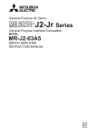
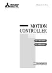
Introducing the Motion Controller Q Series, meeting the
needs for higher performance and smaller size to satisfy
high-speed motion control applications! Compatible with
the Q Series PLC (Platform), which incorporates Multiple
CPU technology, the Motion CPU and PLC CPU are selectable and work in parallel to provide greater flexibility and
unmatched performance. A large-scale control system (Up
to 96 axes per system) can be created using an extremely
compact package as Q Series PLC.
High-Speed Motion Control
■ Cam speed has increased and operation tact time is shortened with a motion operation cycle of
0.88ms (4 times the conventional cycle). (When using the SV13 and 8-axes control.)
■ Accuracy for the synchronous and speed/position control is improved by reducing the command
communication cycle to the servo amplifier to 0.88ms (4 times the conventional cycle).
■ Motion CPU module contains a 64-bit RISC processor for motion control and event processing.
Large volumes of data can be communicated with a personal computer without affecting motion control
performance.
■ Compatible with the high-speed sequence processing of the MELSEC-Q Series PLC CPU (Platform).
(Basic command scan time of 34ns using the Q25HCPU)
■ Various motion functions are included, such as multi-axis interpolation functions, speed control,
software Cam profiles and locus control.
■ Control with suppressed variation in response time is realized using the Motion SFC programming
method as a flowchart.
1
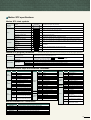
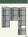
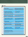
CONTENTS
Main Features ........................................................... 1
System Configuration ................................................ 3
Products Line-up ....................................................... 5
Multiple CPU System ................................................ 7
Motion SFC Program ................................................. 9
SV13 (Conveyor Assenmbly Use)................................. 19
SV22 (Automatic Machinery Use) ................................. 23
Overview of CPU Performance ............................... 27
Device Configuration ............................................... 29
Combinations of Servo Amplifiers and Servomotors ....... 31
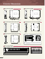
Exterior Dimensions ................................................ 33
Realizing Compact Size and Savings in Space
■ The industry minimum level of mounting area and volume is realized by using the same hardware architecture
as the MELSEC-Q Series PLC CPU. (Volume: 1/3, Area: 60%)
■ Additional savings in space and cost may be realized using a 12-slot base.
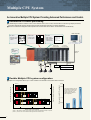
Q Series Multiple CPU System
■ The power supply module, base unit, and I/O modules of the MELSEC-Q Series PLC can be shared.
■ Control processing is distributed to each CPU module among the Multiple CPU system, and it also
corresponds to the intelligent control system.
■ Personal computer technology is utilized using a PC (Personal Computer) CPU module.
A personal computer CPU is the product of CONTEC, Ltd.
Q Series PLC CPU
Device memory
Common memory
Motion CPU
Sequence
control
processor
Device memory
Common memory
Motion
control
processor
SSCNET
Q Series PLC
High-Speed System Bus
Sensor, solenoid, etc.
(DI/O)
PLC intelligent function module
(A/D, D/A, etc.)
Servo
amplifier
Servo
amplifier
Servo
motor
Servo
motor
Motion control dedicated I/F
(DOG signal, pulse generator)
Greater Flexibility
■ Individual CPU modules for PLC control and motion control allow for the economical selection of optimized
CPU's for the system.
■ Up to 4 CPU modules can be freely selected in the Multiple CPU system. (1 PLC CPU must be used.)
■ Up to 96 axes can be controlled per 1 system in the Multiple CPU system. (When using 3 modules of
Q173CPUN.)
Controlling via Mitsubishi SSCNET
■ A synchronous and absolute system for the servomotor can be easily composed using the high-speed serial
communication method.
■ Simple wiring by quick release connection using connectors between the Motion controller and servo amplifiers.
■ Servo amplifiers for up to 32 axes can be batch controlled with 1 CPU.
■ Servomotor of various capacities from 10W to 55kW can be controlled.
■ Motor information such as torque, speed, and position can be batch monitored with the controller using the
digital oscilloscope function.
SSCNET:Servo System Controller NETwork
2
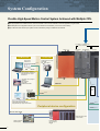
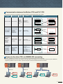
System Configuration
Flexible High-Speed Motion Control System Achieved with Multiple CPU.
■ Compatible with the Q Series PLC (Platform) in the Multiple CPU system.
■ The appropriate CPU modules for PLC control and motion control can be selected to meet the application reguirements.
■ The Multiple CPU configuration allows up to 4 CPU modules to be selected. (1 PLC CPU must be used.)
■ Up to 96 axes of servomotors per system can be controlled by using 3 modules of Q173CPUN.
PLC CPU (Note-1)/Motion CPU
(Up to 4 modules)
Q6
For Motion CPU
P-
Q
CPU
Q17
CPUN
Q172LX
For PLC CPU
SSC I/F card
A30CD-PCF
SSCNET (Note-4)
GX Developer Ver.6 or later
(CD-ROM)
SW D5C-GPPW
USB (Note-5)/RS-232
Laptop personal computer
(WinNT/Win98/Win2000/WinXP)
Integrated start-up support
environment
CPU base Q3 B
Integrated start-up support
software
MT Developer
(CD-ROM)
SW6RNC-GSVPRO
USB/RS-232
(Note-7)
External
battery
SSC I/F board
A30BD-PCF
SSCNET (Note-4)
USB (Note-5)/RS-232
Desktop personal computer
(WinNT/Win98/Win2000/WinXP)
Integrated start-up support environment
SSCNET (Note-7)
Peripheral device configuration
Extension cable QC
SSCNET (Note-7)
B
Motion CPU/PLC CPU
control module
Graphic operation
terminal (GOT)
3
Extension base (Note-6)
(Up to7 stages)
Q6 B
■Operating system software line-up
OS software(FD)
SW6RN-SV
Q
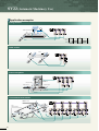
Conveyor Assembly Use
Automatic Machinery Use
Motion SFC
Motion SFC
Provides constant-speed control, speed control, 1 to 4axes linear interpolation and 2-axes circular interpolation,
etc. Ideal for use in conveyors and assembly machines.
Dedicated language
Motion CPU control (Note-2)
modules
Q172EX
Q173PX
• Electronic component assembly
• Inserter
• Loader/Unloader
• Feeder
• Bonding machine
• Molder
• X-Y table
• Conveying equipment
• Paint applicator
• Chip mounter
• Wafer slicer
• Linear interpolation(1 to 4-axes)
• Circular interpolation
• Helical interpolation
• Constant-speed control
• Fixed-pitch feed
• Speed control
• Speed switching control
• Speed-position switching
PLC CPU control (Note-3)
modules
QI60
QX/Y
Provides simultaneous control of the multiple servomotors
and software Cam control. Ideal for use in automatic
machinery.
Mechanical support
language
• Press feeder
• Spinning machine • Tire molder
• Food processing • Textile machine • Knitting machine
• Food packaging • Printing machine
• Winding machine • Book binder
• Spinning machine • Paper-making machine
• Synchronous control • Electronic Cam
• Draw control
• Electronic shaft
• Electronic clutch
(Note-1) : The PLC CPU for Multiple CPU can be used in Q-mode.
(Note-2) : The Motion CPU control module which can be accessed from the PLC CPU is
only input module.
(Note-3) : The other CPU control module cannot be accessed from the Motion CPU.
(Note-4) : Only 1 personal computer can be connected via SSCNET.
(Note-5) : USB cannot be used in Windows NT® 4.0.
(Note-6) : The module installed in the QA1S6 B cannot be controlled in the Motion CPU.
(Note-7) : The external battery for backup of the parameter/program is required at the
continuously power off for 1000 hours or more.
Refer to "SSCNET connecting method" (Page 30) for connection between the
Motion CPU module and servo amplifier/external battery.
(Note-8) : The operation cycle is 1.77ms or more using the MR-H BN.
(Note-9) : When selecting an absolute position system in the MR-J2M-B, connect the
battery unit "MR-J2M-BT".
(Note-10) : Coming soon!
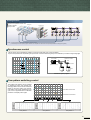
Device configuration
Motion CPU input/output
(Up to 256 points)
External interrupt input (16 points)
Manual pulse generator (3 units per module)
MR-HDP01
Serial absolute synchronous encoder
(2 units per module)
MR-HENC
Servo external signal
(FLS, RLS, STOP, DOG/CHANGE) ✕ 8 axes
Servo amplifier MR-J2M-P8B
Terminal connector
MR-A-TM
Battery unit
MR-J2M-BT (Note-9)
Servo amplifier
MR-H BN (Note-8)
MR-J2S- B
MR-J2- B
MR-J2-03B5
Vector inverter (Note-10)
FR-V5 0Servomotor
/Motor for inverter (Note-10)
Terminal connector
MR-TM
MR-A-TM
Number of servo amplifier/vector inverter (Note-10) SSCNET systems (8 axes per system)
• Q173CPUN: 4 systems (Up to 32 axes) • Q172CPUN: 1 system (Up to 8 axes)
4
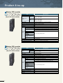
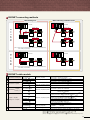
Product-Line-up
Motion CPU module
Q173CPUN
(Up to 32 axes control)
Items
Specifications
Number of control axes
Up to 32 axes
0.88ms : 1 to 8 axes
1.77ms : 9 to 16 axes
SV13
3.55ms : 17 to 32 axes
Operation cycle
0.88ms : 1 to 4 axes
(default)
1.77ms : 5 to 12 axes
SV22
3.55ms : 13 to 24 axes
7.11ms : 25 to 32 axes
External servo amplifiers are connected via SSCNET
Servo amplifier
USB/RS-232/SSCNET
Peripheral I/F
Manual pulse generator operation function Possible to connect 3 modules
Synchronous encoder operation function Possible to connect 12 modules (Note-1) (SV22 use)
5CH
SSCNET I/F
Up to 4 modules per CPU
Q172LX
Up to 6 modules per CPU (SV22 use)
Q172EX
Up to 4 modules per CPU (Incremental synchronous encoder use in SV22)
Q173PX
Up to 1 module per CPU (Only manual pulse generator use)
QX
Controllable QY
modules
QH
QX Y
Total : Up to 256 points per CPU
Q64AD/Q68ADV/Q68ADI/
Q62DA/Q64DA/Q68DAV/
Q68DAI
QI60
PLC extensions
5VDC current consumption [A]
Exterior dimensions [mm(inch)]
Weight [kg]
Up to 1 module per CPU
Up to 7 base units
1.25
H 98(3.86) ✕ W 27.4(1.08) ✕ D 114.3(4.50)
0.23
(Note-1) : Up to 12 modules can be used in the sum total with the manual pulse generator.
Motion CPU module
Q172CPUN
(Up to 8 axes control)
Items
Specifications
Up to 8 axes
0.88ms : 1 to 8 axes
SV13
Operation cycle
0.88ms : 1 to 4 axes
(default)
SV22
1.77ms : 5 to 8 axes
External servo amplifiers are connected via SSCNET
Servo amplifier
USB/RS-232/SSCNET
Peripheral I/F
Manual pulse generator operation function Possible to connect 3 modules
Synchronous encoder operation function Possible to connect 8 modules (Note-1) (SV22 use)
2CH
SSCNET I/F
Q172LX
Up to 1 module per CPU
Q172EX
Up to 4 modules per CPU (SV22 use)
Up to 3 modules per CPU (Incremental synchronous encoder use in SV22)
Q173PX
Up to 1 module per CPU (Only manual pulse generator use)
QX
Controllable
QY
modules
QH
Total : Up to 256 points per CPU
QX Y
Q64AD/Q68ADV/Q68ADI/
Q62DA/Q64DA/Q68DAV/
Q68DAI
Up to 1 module per CPU
QI60
PLC extensions
Up to 7 base units
5VDC current consumption [A]
1.14
Exterior dimensions [mm(inch)]
H98(3.86) ✕ W27.4(1.08) ✕ D114.3(4.50)
Weight [kg]
0.22
Number of control axes
(Note-1) : Up to 8 modules can be used in the sum total with the manual pulse generator.
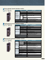
5
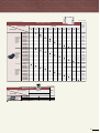
Servo external signals interface module
Q172LX
Items
Upper stroke
limit input,
Lower stroke
limit input,
Stop signal input,
Proximity dog/
speed-position
switching input
Number of input points
Input method
Rated input voltage/current
Operating voltage range
ON voltage/current
OFF voltage/current
Upper/lower
stroke limit and
Response STOP signal
time
Proximity dog/
speed-position
switching signal
Number of I/O occupying points
5VDC current consumption [A]
Exterior dimensions [mm(inch)]
Weight [kg]
Specifications
Servo external control signals : 32 points, 8 axes
Sink/Source type (Photocoupler)
12VDC 2mA, 24VDC 4mA
10.2 to 26.4VDC (Ripple ratio 5% or less)
10VDC or more/2.0mA or more
1.8VDC or less/0.18mA or less
1ms (OFF → ON, ON → OFF)
0.4ms/0.6ms/1ms (OFF → ON, ON → OFF)
CPU parameter setting, default 0.4ms
32 points (I/O allocation: Intelligent, 32 points)
0.05
H98(3.86) ✕ W27.4(1.08) ✕ D90(3.54)
0.15
Synchronous encoder interface module
Q172EX
Items
Serial absolute
synchronous
encoder input
Tracking enable
input
Number of modules
Applicable encoder
Position detection method
Transmission method
Back up battery
Number of input points
Input method
Rated input voltage/current
Operating voltage range
ON voltage/current
OFF voltage/current
Response time
Number of I/O occupying points
5VDC current consumption [A]
Exterior dimensions [mm(inch)]
Weight [kg]
Specifications
2 per module
MR-HENC
Absolute (ABS) data method
Serial communications (2.5Mbps)
A6BAT/MR-BAT
2 points
Sink/Source type (Photocoupler)
12VDC 2mA, 24VDC 4mA
10.2 to 26.4VDC (Ripple ratio 5% or less)
10VDC or more/2.0mA or more
1.8VDC or less/0.18mA or less
0.4ms/0.6ms/1ms (OFF → ON, ON → OFF)
CPU parameter setting, default 0.4ms
32 points (I/O allocation: Intelligent, 32 points)
0.07
H98(3.86) ✕ W27.4(1.08) ✕ D90(3.54)
0.15
Manual pulse generator interface module
Q173PX
Items
Manual pulse
generator/
incremental
synchronous
encoder input
Tracking enable
input
Number of modules
High-voltage
Voltage-output/
Open-collector type Low-voltage
Differential-output High-voltage
type
Low-voltage
Input frequency
Applicable types
Specifications
3 per module
3.0 to 5.25VDC
0 to 1.0VDC
2.0 to 5.25VDC
0 to 0.8VDC
Up to 200kpps (After magnification by 4)
Voltage-output/Open-collector type (5VDC),
(Recommended product: MR-HDP01)
Differential-output type (26LS31 or equivalent)
Cable length
Voltage-output/Open-collector type: 10m(32.79ft.)
Differential-output type: 30m(98.36ft.)
Number of input points
Input method
Rated input voltage/current
Operating voltage range
ON voltage/current
OFF voltage/current
3 points
Sink/Source type (Photocoupler)
12VDC 2mA, 24VDC 4mA
10.2 to 26.4VDC (Ripple ratio 5% or less)
10VDC or more/2.0mA or more
1.8VDC or less/0.18mA or less
Response time
0.4ms/0.6ms/1ms (OFF → ON, ON → OFF)
CPU parameter setting, default 0.4ms
Number of I/O occupying points
5VDC current consumption [A]
Exterior dimensions [mm(inch)]
Weight [kg]
32 points (I/O allocation: Intelligent, 32 points)
0.11
H98(3.86) ✕ W27.4(1.08) ✕ D90(3.54)
0.15
6
Multiple CPU System
An Innovative Multiple CPU System Providing Advanced Performance and Control.
Distribution of control processing
■ By distributing such tasks as machine control, communication control, servo control, and information control among multiple processors,
CPU load is dramatically reduced, allowing extremely fast and efficient processing of complex applications.
■ Various I/O modules are assigned to their respective CPU module and can be used on the same base unit simultaneously.
Host computer
PLC CPU
Motion CPU
PC CPU
• Sequence control
• Communication
control
• Servo control
• Event control
• Data control
• Data collection
• Higher rank
communication
void monitor(void){
int isHot = 0;
int isNot = 0;
isNot = 1;
while(runState ==
:
Motion CPU
control modules
PLC CPU
control modules
GOT
• Data setting
• Monitor
Higher rank
network
SSCNET
Open field network
(CC-Link)
• Usable also as the PC
CPU monitor
Printer
Temperature control module
Electrically operated value
Flexible Multiple CPU system configuration
■ Multiple CPU configuration allows up to 4 CPU modules to be selected for the systems and control axes.
[ms]
MODE
RUN
ERR
USER
BAT
BOOT
Qn(H)
CPU
3
PULL
MODE
RUN
ERR
USER
BAT
BOOT
MODE
RUN
ERR
USER
BAT
BOOT
MODE
RUN
ERR
USER
BAT
BOOT
Q173 Q173 Q173
Q172 Q172 Q172
CPU CPU CPU
PULL
PULL
96
PULL
USB
USB
USB
USB
RS-232
RS-232
RS-232
RS-232
PULL
(Note-2)
POWER
MODE
RUN
ERR
USER
BAT
BOOT
Qn(H)
CPU
2
PULL
MODE
RUN
ERR
USER
BAT
BOOT
POWER
MODE
RUN
ERR
USER
BAT
BOOT
Q173 Q173
Q172 Q172
CPU CPU
PULL
PULL
USB
USB
USB
RS-232
RS-232
RS-232
PULL
MODE
RUN
ERR
USER
BAT
BOOT
MODE
RUN
ERR
USER
BAT
BOOT
MODE
RUN
ERR
USER
BAT
BOOT
MODE
RUN
ERR
USER
BAT
BOOT
Q173 Q173
Qn(H) Qn(H)
CPU CPU Q172 Q172
CPU CPU
PC
CPU
PULL
PULL
PULL
USB
USB
USB
RS-232
RS-232
RS-232
MODE
RUN
ERR
USER
BAT
BOOT
MODE
RUN
ERR
USER
BAT
BOOT
(Note-2)
POWER
MODE
RUN
ERR
USER
BAT
BOOT
Qn(H)
CPU
1
PULL
Q172
CPU
PULL
USB
RS-232
(Note-2)
POWER
MODE
RUN
ERR
USER
BAT
BOOT
Q173
USB
PULL
64
PULL
USB
RS-232
PULL
POWER
MODE
RUN
ERR
USER
BAT
BOOT
Q173
PC
CPU
RS-232
Qn(H) Qn(H)
CPU CPU Q172
CPU
PULL
PULL
USB
RS-232
1
PULL
USB
USB
PULL
RS-232
MODE
RUN
ERR
USER
BAT
BOOT
MODE
RUN
ERR
USER
BAT
BOOT
MODE
RUN
ERR
USER
BAT
BOOT
MODE
RUN
ERR
USER
BAT
BOOT
Q173
PC
CPU
Qn(H) Qn(H) Qn(H)
CPU CPU CPU Q172
CPU
PULL
PULL
PULL
32
PULL
USB
USB
USB
USB
RS-232
RS-232
RS-232
RS-232
PULL
RS-232
2
3
Number of PLC CPU modules
(Note-1) : Be careful of a 5VDC power supply capacity. Select the Q64P (5VDC 8.5A) as required.
(Note-2) : The PC CPU can be installed to the right-hand side of Motion CPU.
7
Number of maximum control axes
Number of Motion CPU modules
POWER
Motion operation cycle(SV13 use/default)
(Note-1)
3.55
The motion operation cycle can
be selected in the Motion CPU.
Priority is given to the number
of axes or operation cycle
(specifications) to select the
CPU configuration.
1.77
0.88
1 to 8
9 to 16
17 to 32
Number of control axes
Communication between the Motion CPU and PLC CPU
■ The optimum functions for your application needs are provided to exchange data between CPU modules.
Communication
method
Automatic refresh
Communication
processing timing
Scan processing
Data
amount
Several
hundred
words to
several kilo
words
Function
Data exchange
(Area-fixed)
(Parameter-fixed)
Application
PLC CPU (CPU No.1)
Motion CPU (CPU No.2)
Shared memory
Shared memory
Read
(Main processing)
Automatic refresh area
Write
(END processing)
Device memory
B0~B1F(CPU No.1)
B20~B3F(CPU No.2)
Automatic refresh area
Write
(Main processing)
Device memory
B0~B1F(CPU No.1)
B20~B3F(CPU No.2)
Read
(END processing)
Regular communication for control device data
PLC CPU
Motion dedicated
PLC instruction
S(P).DDRD
S(P).DDWR
Direct processing
(At the command
execution)
Interrupt
request to the
Motion CPU
1 to 16
words
Data exchange
(Random access)
Motion CPU
SP.DDWR
instruction
Read the device
memory
Device memory
Write the device
memory
Device memory
Re-writing of the position follow-up control data, etc.
PLC instruction
FROM
S(P).TO
Motion SFC
instruction
MULTR
MULTW
Direct processing
(At the command
execution)
PLC CPU
Motion CPU
Shared memory
Shared memory
User defined area
1 to 256
words
Data exchange
(Shared memory batch)
User defined area
Read the MULTR
instruction
Write the SP.TO instruction
PLC program
SP.TO instruction
execution
Motion SFC
MULTR instruction
execution
Batch data communication
PLC CPU
Motion dedicated
PLC instruction
S(P).SFCS
S(P).GINT
S(P).SVST
S(P).CHGA
S(P).CHGV
S(P).CHGT
Direct processing
(At the command
execution)
Interrupt
request to the
Motion CPU
–
Execution of
Motion SFC program/
Event task/
Servo program/
Current value change/
Speed change/
Torque limit value change/
Motion CPU
Motion SFC program
Start request
SP.SFCS
instruction
Program start, event execute control
Access to the other CPU via USB/RS-232 connecting
■ Access to the Motion CPU and PLC CPU on the same base unit is possible using one personal computer.
The programming/monitor of other CPU modules on the same base unit is possible, by only connecting a personal computer installed the
programming software to one CPU module. A personal computer can also be connected with each CPU module.
USB/RS-232
USB/RS-232
MT
Developer
MT
Developer
GX
Developer
GX (Note)
Developer
USB/RS-232
USB/RS-232
GX
Developer
MT
Developer
(Note) Use the Version 6.05F or later.
8
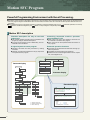
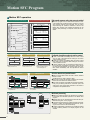
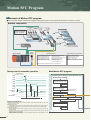
Motion SFC Program
Powerful Programming Environment with Event Processing.
■ The Motion control program is described in flowchart form using the Motion SFC (Sequential Function Chart) format. By describing the Motion CPU program using the suitable Motion SFC function blocks, the Motion CPU can control the machine operation and aid in the event
processing.
■ Easy programming for the entire system operation is possible by using the available icons such as
(Arithmetic Operation, I/O Control),
(Transition Conditional Judgement) and
(Motion Control) arranged in a sequential process.
Motion SFC description
Flowchart description are easy to read and
understand
Controlling sequential machine operation
using the Motion CPU
● The machine operation procedure can be visualized in the
program by using the flowchart descriptions.
● A process control program can be created easily, and control details can be visualized.
● Servo control, I/O control, and operation commands can
be combined in the Motion SFC program.
● Servo control can be accomplished without the need for a
PLC program.
A logical layered structure program
Enhanced operation functions
● Operation commands are easily described by creating
comments.
● Operation commands are detailed in a step by step format
in a layered structure program.
● Commands can be described with arithmetic and logic operation expressions.
● Compatible with 64-bit floating-point operations.
● Arithmetic functions include trigonometric functions, square
root, natural logarithm, etc.
Reduced display
G100
G120
Beginning wait
Cancellation wait
F30
F40
Data calculation
Cancellation data set
Seal processing
G200
Work ready
P10
K100
Operation start
F10
Comment display
P20
F20
G100
G120
G150
F30
F40
G160
Extended display
G200
K200
K100
G210
[F 30]
// 1 axis real processing data calculation
DOL=LONG((SIN(#100)+110F) 300)
// Processing status set
SET M100=X12+M120
*
P20
G300
[G 200]
PXO //Work ready completion sensor ON?
F150
P10
9
F : Operation control step
G : Transition (condition wait)
K : Motion control step
[K 100]
1 ABS-2
Axis
1,
# 100 µm
Axis
2,
# 200 µm
Combined-speed # 300 mm/min
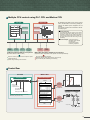
Multiple CPU control using PLC CPU and Motion CPU
PLC CPU
Motion CPU
Device memory
Device memory
Shared memory
Shared memory
By distributing such tasks as servo control, machine
control, and information control among multiple processors, the flexible system configuration can be
realized.
The program of Motion CPU is described in the Motion SFC program.
Event processing
The high-speed response (control for the signal
output, servomotor start, speed change, etc.) is
executed by waiting for the condition completion
(event occurrence) according to the change of input signal state and device value change in this
processing.
Event examples . Input signal turned on
. Operation results reached
constant-value
. Constant-time passed
. Positioning completed
MELSEC
intelligent
module
MELSEC
I/O module
MELSEC
display unit
MELSEC
communication
module
MELSEC
I/O module
(PX/PY)
Motion related
module
Ladder description suitable for scan process
Motion SFC description suitable for event process
(Importance laid on condition control)
(Importance laid on sequential control, pursuit of event responsiveness)
Sequence control (Compatible with multiple I/O points,
multiple operations)
System stop processing at error detection
Servo high-speed response (Start)
Positioning address, speed data operation, speed change
High functionality with multitasking and branching
Control flow
PLC CPU
Motion CPU
PLC program
Motion SFC program
Axis 2
20000
SP.SFCS
H3E1
K0
Transfer
[G100]
M2049 // Servo ON accept?
Motion SFC
program start
request instruction
Target CPU (No.1)
specification
Start program No. specification
Motion SFC program also can be automatically
started by the parameter setting.
[K10 : Real]
1 INC-2
Axis
1, 10000 PLS
Axis
2, 20000 PLS
Combined-speed 30000 PLS/s
10000
SV13/SV22
real mode
10000
20000
Axis1
Servomotor start
Mechanical system program
[F100]
// Command speed calculation
#OL=#100L+#102L+#104L
Drive module
Transmission
module
(Virtual servomotor)
[G200]
M2044//On virtual mode?
[K100 : Virtual]
1 VF
Axis
1
Speed
SV22
virtual mode
# 0 PLS/s
Virtual servomotor
start
END
Output module
(Cam)
(Roller)
10
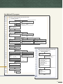
Motion SFC Program
Motion SFC operation
PLC program (Note)
Motion SFC program
All steps are executed with constant scanning.
Only active steps are executed following transition conditions.
X0000
PLS
M100
SET
M101
Work travel control
M100
[G 1]
PX0 //Start (PX0:ON) wait
M101 M2001 M2002
RST M101
[K 1]
1 ABS-2
Axis
1,
# 200 µm
Axis
2,
# 202 µm
Combined-speed # 204 mm/min
SET
[G 2]
PX1 //1st process machining completion (PX1: ON) wait
SVST J1 J2
K1
M102
M102 M2001
SVST J1
[K 2]
1 ABS-1
Axis
Speed
K2
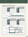
High-speed response using step execute method
■ The PLC program uses a scan execute method to execute all steps with constant scanning. However, since the
step execute method which executes only the active
steps following the transition conditions is used in the
Motion SFC program, the operation processing can be
reduced, and processing or response control can be realized.
# 300 µm
# 302 mm/min
1,
RST M102
SET
M103
SET
Y0008
[G 3]
PX2 //2nd process machining completion (PX2: ON) wait
[F 1]
SET PY8 //Complete signal (PY8) ON
M103 M2001
END
RST M103
(Note): A172SHCPUN, SV13 use
WAIT
Shift
WAIT ON/OFF
K100
K200
ON M0
G100
G200
K300
■ Execute G100 without waiting for
K100 operation to end
■ Execute G200 after waiting for
K200 operation to end
■ Pre-read K300 and prepare to start
■ Start immediately with the
specified bit (M0) ON
Selective branch
Selective branch and parallel branch
Parallel branch
GO
K1
G1
G2
G3
K2
K3
F1
K2
K3
K4
G1
G2
G3
G6
F2
G4
G4
Wait
F
F
P
P
G
Parallel branch
K
F
K
G
G
G
F
F
F
F
F
Selective branch
G
G
G
K
K
P
G
END
G
F
P
11
Multi-task processing
SUB
REAL
F
■ When all routes after branch are shift or WAIT, selective
branch is used.
Parallel branch is used in all other cases.
■ The route for which the transition conditions are completed first are executed in the selective branch.
■ The routes connected in parallel are executed simultaneously, the processing waits at the connection point, and
shifts to the next process after execution of all routes is
completed in the parallel branch.
■ Simultaneously execute all routes for step K2 to
F1 in parallel
■ Judge G1 to G3 conditions, and execute only
completed route
MAIN
Dedicated description unique to motion control
■ If shift is executed immediately after the motion control
step, the shift is executed without waiting for the motion
control operation to end.
■ If WAIT is executed immediately after the motion control
step, WAIT will be executed after waiting for the motion
control operation to end.
■ If WAIT ON/WAIT OFF is executed just before the motion control step, the details of the motion control will be
pre-read, and preparations for start are made. The operation starts immediately with the specified bit device
ON/OFF.
■ When the multiple programs are started, the processing
is executed with multi-task operation in the Motion SFC
program.
■ Multiple steps can be simultaneously executed with parallel branching even in one program.
■ A program that executes the multiple processing simultaneously or makes the independent movement by grouping the control axes can be created easily.
■ A highly independent programming is possible according
to the processing details, so a simple program can be
created.
Task operation examples of Motion SFC program
Normal task
Program 1
Program 2
• Normal task
• Do not start automatically
F20
F30
F1
F5
F2
F6
F3
F7
END
F8
• Normal task
• Do not start automatically
END
S(P).SFCS (Program 1 start)
S(P).SFCS (Program 2 start)
Timing chart
PLC program
Main cycle
Main cycle
Main cycle
Execute timing of normal task
(Program 1, Program 2)
Event task/NMI task
Program 1
F100
Program 2
• Event task
(External interrupt, PLC interrupt)
• Do not start automatically
F200
F110
F210
F120
F220
F130
F230
F140
F240
END
END
Timing chart
• Event task
(Fixed cycle : 1.77ms)
• Do not start automatically
S(P).SFCS (Program 1 start)
S(P).SFCS (Program 2 start)
S(P).GINT (Execute reguest of event task)
PLC program
EI/DI state by other program
EI
DI
EI
External interrupt
Execute timing of event task
(Program 1)
Memorize event occurrence
during DI, and execute
1.77ms
Fixed cycle interrupt (1.77ms)
Execute timing of event task
(Program 2)
Event task execute disable during DI
Execute with new event
(Note): Number of steps executed in 1 time of processing cycle are set in the parameters.
12
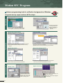
Motion SFC Program
Various programming tools in a effective background on Windows
Integrated start-up support software MT Developer
Servo data setting
System design
System setting
■ Set the servo parameter
or fixed parameter, etc.
■ Display explanations of
parameters with onepoint help
■ Set the system configuration (Motion module,
servo amplifier, servomotor) with menu selection
Motion SFC program editing
Program editing
Start-up adjustment
Programming
Select instruction
13
Instruction wizard
Instruction wizard
■ Describe machine operation procedures with flow chart format
■ Lay out graphic symbols by clicking mouse and connect by
dragging
■ Program for each step and transition
■ Selection with menu is also possible using command wizard
Motion SFC monitor
Motion SFC debugging mode
■ Color display of executing step on flow chart
■ Device monitor and test of execution/specification
■ Greatly reduced debugging time with powerful debug function
(One-step execution/Forced shift/Brake/Forced end)
Monitor • Test
Digital oscilloscope
■ Current value monitor/axis
monitor/error history monitor
■ Various tests such as home
position return and JOG operation by clicking mouse
■ Data sampling synchronized with
motion control cycle
■ Waveform display/dump display/file
save/printing
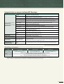
Integrated start-up support software MT Developer
Function
• Installation of operating system (OS)
• Comparison of operating system (OS)
• New creation, setting and reading of projects
• Batch management of user files in project units
• Setting of system configuration (Motion module, servo amplifier or servomotor, etc.)
• Setting of high-speed reading data
• Setting of servo parameters or fixed parameters, etc. (Display explanation with one-point help)
• Setting of limit switch output data (Output pattern display with waveform display function)
Software
Installation
Project management
System setting
Servo data setting
Conveyor assembly software
SW6RN-GSV13P
Program editing
Automatic machinery software
SW6RN-GSV22P
Mechanical system editing
(GSV22P only)
• Editing of Motion SFC program/Setting of Motion SFC parameters
• Reduced display, comment display and extended display of Motion SFC chart
• Motion SFC monitor/Motion SFC debug
• Editing of mechanical system program
• Monitoring of mechanical system program execute state
• Setting of SSCNET communication CH/Communication setting between USB and RS-232
• Writing, reading and comparison of programs and parameters for Motion controller
• Current value monitor/Axis monitor/Error history monitor
• Servo monitor/Limit switch output monitor
• Servo startup/Servo diagnosis
• Jog operation/Manual pulser operation/Home position return test/Program operation
• Teaching/Error reset/Current value change
• Backup of Motion controller programs and parameters in file
• Batch writing of backed up files to Motion CPU
• Cam data creation with Cam pattern selection and free curve settings
• Graphic display of Cam control state
• Data sampling synchronized to operation cycle
• Waveform display, dump display and file saving of collected data
Communication
Monitoring
Test
Backup
Cam data creation software
SW3RN-CAMP
Digital oscilloscope software
SW6RN-DOSCP
Cam data creation
Digital oscilloscope
Communication system software Communication system
Communication API
SW6RN-SNETP
• Communication task/Communication manager/Common memory server/SSCNET
communication driver
• Support of cyclic communication, transient communication, high-speed refresh communication
• Communication API functions compatible with VC++/VB
Document printing software
SW3RN-DOCPRNP (Note-1)
SW20RN-DOCPRNP (Note-2)
• Printing of programs, parameters and system settings
(Convert into Word 97, Excel 97 or Word 2000 and Excel 2000 document format, and print)
Printing
(Note-1) : Word 97 and Excel 97 are required.
(Note-2) : Word 2000 and Excel 2000 are required.
Operating environment
IBM PC/AT with which WindowsNT4.0/98/2000/XP English version operated normally.
®
Item
CPU
Memory capacity
Hard disk free space
Display
Application software
®
®
WindowsNT 4.0 (Service Pack 2 or later)
Windows 2000
Windows XP
®
or Windows 98
Recommended Pentium® 133MHz or more Recommended Pentium® 233MHz or more Recommended Pentium® 450MHz or more
Recommended 32MB or more
Recommended 64MB or more
Recommended 192MB or more
SW6RNC-GSVE: 160MB + SW6RNC-GSVHELPE: 85MB (Possible to select installation)
SVGA (Resolution 800 ✕ 600 pixels, 256 colors) or more
Word 97, Excel 97 or Word 2000, Excel 2000 (For document printing)
Visual C++ 4.0 or more, Visual Basic 4.03 (32 bit) or more (For communication API function)
®
(Note) • When using the A30CD-PCF, the PC card driver for WindowsNT provided by the personal computer manufacturer must be used.
®
®
• WindowsNT , Windows , Word, Excel, Visual C++ and Visual Basic are either registered trademarks or trademarks of Microsoft Corporation in the United States and/or other countries.
®
• Pentium is trademarks or registered trademarks of Intel Corporation or its subsidiaries in the United States and other countries.
14
Motion SFC Program
Motion SFC high-speed response control
High-speed response to external inputs
PLC program (A172SHCPUN)
X10
Motion SFC program (Q173CPUN)
[G100]
SET PY0 = PX10 M100
Y0
PLC scan time 20ms
OFF
X10
(Input)
PX10
(Input)
ON
OFF
Y0
(Output)
PY0
(Output)
I/O output
■ The response time of output signal for the input signal from an external source is measured in this program.
■ The response time and dispersion affected by
the scan time are approx. 20ms in the PLC
program of A172SHCPUN.
■ The response time and dispersion are approx.
3ms in the Motion SFC program.
M100
OFF
ON
OFF
ON
ON
5ms/div
5ms/div
~20ms
(Approx. PLC scan time)
~3ms
■ Input module:A1SX40-S1
(OFF ON response:~0.1ms)
■ Input module:QX40-S1
(OFF ON response:~0.1ms)
■ Output module:A1SY40
(OFF ON response:~2ms)
■ Output module:QY40P
(OFF ON response:~1ms)
Powerful reduction in servo program start time
PLC program (A172SHCPUN)
Motion SFC program (Q173CPUN)
X10 M2001
ON PX0010
SVST J1 K100
K100
PLC scan time 20ms
OFF
X10
(Input)
ON
OFF
PX10
(P-I/O input)
ON
Speed command
(Amplifier monitor terminal)
Speed command
(Amplifier monitor terminal)
10ms/div
Servo program start
■ The servo program is started using the input
signal from an external source as a trigger in
this example.
■ The response time and dispersion are affected by the scan time from the external signal
input to starting of speed command is approx.
20ms in the start using the PLC program of
A172SHCPUN.
■ The speed command is started with the response time “2 ms or less” and dispersion
“approx. 0.5ms” in the Motion SPC program.
10ms/div
~20ms
1.1ms~1.6ms
(Approx. PLC scan time)
■ Input module:A1SX40-S1
(OFF ON response:~0.1ms)
PLC program (A172SHCPUN)
■ Input module:QX40-S1
(OFF ON response:~0.1ms)
Motion SFC program (Q173CPUN)
M10 M2001 M2002
RST M10
M20 M2001 M2003
G100
SET M20
SVST J1J3 K300
K300
PLC scan time 20ms
Speed command
Speed command
Axis 1
Axis 1
Axis 2
Axis 2
Axis 3
Axis 3
10ms/div
~30ms
(Approx. "PLC scan time + 10ms")
■ Input module:A1SX40-S1
(OFF ON response:~0.1ms)
15
Servo program continuous start
■ 1 axis, 3 axes linear interpolation program
“K200” is started following 1 axis, 2 axes linear interpolation program “K300” in this example.
■ The response time and dispersion are approx. 30ms in the servo program continuous
start using the PLC program of A172SHCPUN.
This is because the PLC scan time is 20ms,
and the refresh cycle of start accept flag
M2000 used as the interlock is 10ms.
■ An interlock is not required and the start delay is approx. 5.5 in the Motion SFC program.
K200
SVST J1J2 K200
10ms/div
~5.5ms
■ Input module:QX40-S1
(OFF ON response:~0.1ms)
Motion SFC specifications
Motion SFC chart symbols
Class
Name
Symbol
START
Program
start/end
Step
Program name
Function
Indicates the program start (entrance) .
END
END
Indicates the program end (exit) .
Motion control step
K
Starts the servo program Kn.
(Refer to page 20 for the servo instructions.)
Once execution type operation control step
F
Executes the operation control program Fn once.
Scan execution type operation control step
FS
Subroutine call/start step
Repeats an operation control program FSn until the completion of next transition condition.
Program name
Clear step
CLR Program name
Shift (Pre-read transition)
G
WAIT
G
Calls or starts a subroutine.
Cancels and ends the execution of specified program.
Shifts to the next step with the completion of condition without waiting for the previous
motion control step or subroutine to end.
Shifts to the next step with the completion of condition after the previous motion control
step or subroutine end.
Transition
WAIT ON
ON bit device
WAIT OFF
OFF bit device
Prepares to start the next motion control step, and immediately commands the completion
of condition.
Jump
Jump
P
Jumps to the specified pointer Pn of the self program.
Pointer
Pointer
P
Indicates the jump destination pointer (label).
Motion SFC program parameters
The Motion SFC program start method and execute timing are set with the program parameters.
Details
Setting range
Item
Start setting
Execute task
Start automatically
• Starts at the turning PLC ready (M2000) off to on.
Do not start automatically
• Starts with the Motion SFC program start instruction S(P).SFCS .
• Starts with the "Subroutine call/start" GSUB from the Motion SFC program.
Normal task
• Executes in the motion main cycle (free time).
Event task
Fixed cycle
• Executes in the fixed cycle (0.88ms, 1.77ms, 3.55ms, 7.11ms, 14.2ms).
External interrupt
• Executes when input ON is set among the interrupt module (QI60 16 points).
PLC interrupt
• Executes with interrupt from PLC (PLC dedicated instruction S(P).GINT is executed.).
• Executes when input ON is set among the interrupt module (QI60 : 16 points).
NMI task
Operation control steps and transition commands
Class
Binary
operation
Bit
operation
Sign
Type
conversion
Symbol
=
+
–
*
/
%
˜
&
I
ˆ
>>
<<
–
SHORT
USHORT
LONG
ULONG
Function
Class
Substitution
Addition
Subtraction
Multiplication
Division
Remainder
Bit inversion (complement)
Bit logical AND
Bit logical OR
Bit exclusive OR
Bit right shift
Bit left shift
Sign inversion (complement of 2)
Convert into 16-bit integer type (signed)
Convert into 16-bit integer type (unsigned)
Convert into 32-bit integer type (signed)
Convert into 32-bit integer type (unsigned)
FLOAT
Regarded as signed data,
and convert into 64-bit floating point type
UFLOAT
Regarded as unsigned data,
and convert into 64-bit floating point type
Standard
function
Bit device
status
Bit device
control
Symbol
Function
SIN
COS
TAN
ASIN
ACOS
ATAN
SQRT
LN
EXP
ABS
RND
FIX
FUP
BIN
BCD
(none)
!
SET
RST
DOUT
DIN
OUT
Sine
Cosine
Tangent
Arcsine
Arccosine
Arctangent
Square root
Natural logarithm
Exponential operation
Absolute value
Round off
Round down
Round up
BCD → BIN conversion
BIN → BCD conversion
ON (normally open contact)
OFF (normally closed contact)
Device set
Device reset
Device output
Device input
Bit device output
Motion dedicated PLC instructions
Instructions
S(P).SFCS
S(P).GINT
S(P).SVST
S(P).CHGA
S(P).CHGV
S(P).CHGT
S(P).DDRW
S(P).DDRD
Class
Logical
operation
Comparison
operation
Motion
dedicated
function
Others
Symbol
(none)
!
*
+
==
!=
<
<=
>
>=
CHGV
CHGT
EI
DI
NOP
BMOV
TIME
Function
Logical acknowledgement
Logical negation
Logical AND
Logical OR
Equal to
Not equal to
Less than
Less than or equal to
More than
More than or equal to
Speed change request
Torque limit value change request
Event task enable
Event task disable
No operation
Block move
Time to wait
MULTW
Write device data to shared
CPU memory
MULTR
Read device data from shared
CPU memory of the other CPU
TO
FROM
Write device data to intelligent/
special function module
Read device data from intelligent/
special function module
Control details
Requests to start the specified Motion SFC program.
Requests to start the event task of Motion SFC program.
Requests to start the specified servo program.
Amends the current value of specified axes.
Amends the speed of specified axes.
Amends the torque control value of specified axes.
Writes the PLC CPU device data to the Motion CPU devices.
Reads the PLC CPU device data to the Motion CPU devices.
16
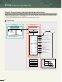
Motion SFC Program
Example of Motion SFC program
■ This is a control example of assortment equipment which judges 3 types work and performs assortment conveyance on 3 lines.
Machine composition
Long work :PH1 to PH3 ON
Middle work :PH2 and PH3 ON
Short work :Only PH3 ON
Length judgement Work detected Work detected
sensor
timing sensor sensor (IN)
PH1 PH2 PH3 PH0
PH4
Work detected
sensor (OUT)
PH5
Ball
screw
a-point
Inport
conveyer
Long work
export conveyor
Work
b-point
Middle work
export conveyor
(Waiting point)
Length:3 types
c-point
Geared
motor (GM)
Servomotor
(Axis 1)
PB, SW
Short work
export conveyor
(Note) : Control of inport/export
conveyor is not included.
Motion controller
Servo
amplifier
I/O signal allocation
PX00:Work detection timimg sensor PH0
PX01:Length judgement sensor PH1
PX02:Length judgement sensor PH2
PX03:Length judgement sensor PH3
PX04:Work detection sensor PH4(IN)
PX05:Work detection sensor PH5(OUT)
Motion dedicated device allocation
PX06:Automatic mode selection SW
PX07:Automatic start PB
PX08:Automatic cycle temporary stop SW
PX09:Forward rotation JOG PB
PX0A:Reverse rotation JOG PB
PX0B:Conveyor JOG PB
M2001:Axis 1 start accept monitor
M2042:All axes servo ON command
M2402:Axis 1 in-position signal
M3200:Axis 1 stop command
M3202:Axis 1 forward rotation JOG command
M3203:Axis 1 reverse rotation JOG command
PY10:Conveyor GM drive output
“Real input/output” is expressed as “PX/PY” in the Motion CPU.
Main Motion SFC program
Timing chart of automatic operation
Length judgement
(Example for long work)
Operating mode switching program (Automatic start)
PX00
Operation mode switching
PX01
PX02
[F110]
SET M2042 //All axes servo ON command
PX03
PX04
P0
PX05
PX06
[G105]
M2415 //Axis 1 servo ON ?
PX07
Servomotor
(Axis 1)
b-point
(Waiting point)
a-point
(Long work)
b-point
(Waiting point)
PY10
Geared motor
Work input
Work output
• PX6 ON : Call “Automatic operation”
• PX6 OFF : Call “Manual operation”
[G110]
PX6 //Automatic operation mode ?
Automatic operation
Manual operation
Automatic operation 1 cycle
Operation specifications
■ Automatic operation mode is set by turning the automatic mode selection SW(PX06) ON, and manual
operation mode is set by OFF.
■ Manual operation mode
• JOG operation of servomotor is executed with the forward rotation JOG (PX09)/reverse rotation JOG (PX0A).
• JOG operation (export direction only) of geared motor is executed with the conveyor JOG PB (PX0B).
■ Manual operation mode
• Automatic operation cycle (assortment conveyance) shown in a chart is started by turning the automatic
start PB (PX07) ON.
• Automatic operation cycle is stopped temporality by turning the automatic cycle temporary stop SW
(PX08) ON, and it is resumed by OFF.
• Automatic operation cycle is stopped by turning the automatic mode selection SW (PX06) OFF, and it
shifts to the manual operation mode.
17
[G115]
//Wait a subroutine call completion
NOP
P0
Sub Motion SFC program
Automatic operation program (Not automatic start)
Automatic operation
• Subroutin end with PX6 OFF
[G10]
PX7 //Automatic start ON?
[G20]
!PX6 //Switch to manual operation mode?
P0
END
• Positioning to b-point (Waiting point)
[K150:Real]
1 ABS-1
Axis 1, 400000.0µm
Speed 10000.00mm/min
[G140]
M2402 //Axis 1 in-position signal ON?
• Waiting for work detection
[G150]
// (Work detection timing sensor ON)
//AND (Automatic cycle temporary stop OFF)?
PX0 !PX8
[G152]
!PX6 //Switch to manual operation mode?
END
• Selective branch based on detection
result length judgement sensor
[G154]
PX1 PX2 PX3 //Long work?
[G156]
!PX1 PX2 PX3 //Middle work?
[G158]
!PX1 !PX2 PX3 //Short work?
[F150]
#0L=6000000 //a-point position set
[F152]
#0L=4000000 //b-point position set
[F154]
#0L=2000000 //c-point position set
[G160]
PX4 //Work detected sensor (IN) ON?
[F156]
SET PY10 //Conveyor start
Manual operation program (Not automatic start)
• Parallel branch
(Execute 2 routes simultaneously)
[G162]
!PX4 //Work detected sensor(OUT) OFF?
• Positioning to a, b or c-point based on work length
[K152:Real]
1 ABS-1
Axis
1,
# 0µm
Speed
10000.00mm/min
[F158]
RST PY10 //Conveyor stop
[G140]
M2402 //Axis 1 in-position signal ON?
• Wait until completion of 2 routes
[F160]
SET PY10 //Conveyor start
[G168]
!PX5 //Work detected sensor (OUT) OFF?
Manual operation
[G164]
PX5 //Work detected sensor(OUT) ON?
[F120]
//Axis 1 JOG operation speed set
D640L=100000
• JOG operation of servomotor (axis 1)
and geared motor (GM)
• Repeat until PX6 is turned on
[G120]
//Axis 1 forward rotation JOG command SET/RST
SET M3202=PX9 !M3203
RST M3202=!PXA
//Axis 1 reverse rotation JOG command SET/RST
SET M3203=PX9 !M3202
RST M3203=!PXA
//GM drive output SET/RST
SET PY10=PXB
RST PY10=!PYB
//Repeat until automatic mode switching
PX6
• JOG command is turned off with PX6
OFF, and subroutine end
[F162]
RST PY10 //Conveyor stop
P0
[F122]
//Axis 1 forward/reverse rotation JOG command RST
RST M3202
RST M3203
//GM drive output RST
RST PY10
END
18
SV13 (Conveyor Assembly Use)
Simple Programming Using Dedicated Instructions.
■ Colorful positioning controls and locus controls such as “1 to 4 axes linear interpolation, 2 axes circular interpolation, helical interpolation,
positioning control, speed control or constant-speed control” are supported. Particularly simple programming for positioning systems is
attained by using dedicated servo and PLC instructions.
A variety of enhanced functions allow easy programming of conventionally complex systems.
Control flow
PLC CPU
Motion CPU
PLC program
Motion SFC program
SP.SFCS
......
K0
......
......
Motion SFC
program start
request instruction
2-axes constant-speed control
[G100]
M2049 // Servo ON accept ?
Servo amplifier
Servomotor
Servo program
Start program No. specification
[K10 : Real]
Motion SFC program also can be automatically
started by the parameter setting.
5 CPSTART2
Axis
1,
Axis
2,
Speed 1000.00mm/min
2-axes constant-speed control
1 INC-2
Axis
Axis
Incremental linear interpolation
Combined-speed setting
1, 10000.0 m
2, 12500.0 m
2 ABS
Axis
1, 18500.0
Axis
2, 7500.0
Auxiliary P 1, 13500.0
Auxiliary P 2, 14750.0
M-code
3 ABS-2
Axis
1,
Axis
2,
M-code
m
m
m
m
10
Absolute auxiliary point specified
circular interpolation
M-code output
Absolute linear interpolation
2000 m
2002 m
11
4 ABS-2
Axis
1,
0.0 m
Axis
2,
0.0 m
M-code
12
Speed 800.00mm/min
Indirect setting
M-code output
Absolute linear interpolation
M-code output
Combined-speed setting
5 CPEND
END
Positioning parameter
System setting
Fixed parameter
Servo parameter
Parameter block
Axis 2
14750
12500
7500
Home position return data
JOG operation data
Limit switch setting
19
2500
10000
Axis 1
16000
13500 18500
Servo instructions
Absolute 3-axes linear
interpolation
ABH
Absolute radius-specified
helical interpolation less than
CCW 180˚
INC-3
Incremental 3-axes linear
interpolation
ABH
Absolute radius-specified
helical interpolation CCW 180˚
or more
ABS-4
Absolute 4-axes linear
interpolation
INH
Incremental radius-specified
helical interpolation less than
CW 180˚
INC-4
Incremental 4-axes linear
interpolation
INH
Incremental radius-specified
helical interpolation CW 180˚
or more
INH
Incremental radius-specified
helical interpolation less than
CCW 180˚
Absolute auxiliary point-specified
circular interpolation
INC
Incremental auxiliary point-specified
circular interpolation
INH
Incremental radius-specified
helical interpolation CCW 180˚
or more
ABS
Absolute radius-specified
circular interpolation less than
CW 180˚
ABH
Absolute central point-specified
helical interpolation CW
ABS
Absolute radius-specified
circular interpolation CW 180˚
or more
ABH
Absolute central point-specified
helical interpolation CCW
ABS
Absolute radius-specified
circular interpolation less than
CCW 180˚
INH
Incremental central point-specified
helical interpolation CW
ABS
Absolute radius-specified
circular interpolation CCW 180˚
or more
INH
Incremental central point-specified
helical interpolation CCW
INC
Incremental radius-specified
circular interpolation less than
CW 180˚
INC
Incremental radius-specified
circular interpolation CW 180˚
or more
INC
Incremental radius-specified
circular interpolation less than
CCW 180˚
INC
Incremental radius-specified
circular interpolation CCW 180˚
or more
ABS
Absolute central point-specified
circular interpolation CW
ABS
Absolute central point-specified
circular interpolation CCW
INC
Incremental central point-specified
circular interpolation CW
INC
Incremental central point-specified
circular interpolation CCW
Central point-specified
ABS
Fixed-pitch feed
ABS-3
FEED-1
1-axis fixed-pitch feed start
FEED-2
2-axes linear interpolation
fixed-pitch feed start
FEED-3
3-axes linear interpolation
fixed-pitch feed start
VF
Speed control (I) forward rotation
start
VR
Speed control (I) reverse rotation
start
VVF
Speed control (II) forward rotation
start
VVR
Speed control (II) reverse rotation
start
VPF
Speed-position control
forward rotation start
VPR
Speed-position control
reverse rotation start
VPSTART Speed-position control restart
VSTART
Speed switching control start
VEND
Speed switching control end
VABS
Speed switching point
absolute specification
VINC
Speed switching point
incremental specification
PFSTART Position follow-up control start
CPSTART1 1-axis constant-speed control start
CPSTART2 2-axes constant-speed control start
CPSTART3 3-axes constant-speed control start
CPSTART4 4-axes constant-speed control start
CPEND
Constant-speed control end
FOR-TIMES
FOR-ON
Repeat range start setting
FOR-OFF
NEXT
Repeat range end setting
START
Simultaneous start
ZERO
Home position return start
OSC
High-speed oscillation start
CHGA
Servo/virtual servo current value
change
Encoder
Absolute radius-specified
helical interpolation CW 180˚
or more
Processing
CHGA-E
Encoder current value change
CAM
ABH
Speed control
( )
Incremental 2-axes linear
interpolation
Speed control
( )
INC-2
Forward Reverse Forward Reverse Forward
Restart Reverse
rotation rotation rotation rotation rotation rotation 3 axes 2 axes 1 axis
Absolute radius-specified
helical interpolation less than
CW 180˚
ABS-2
Speed-position
control
ABH
Incremental 1-axis positioning
Speed switching control
Absolute 2-axes linear
interpolation
INC-1
Position
follow-up
control
Incremental auxiliary point-specified
helical interpolation
Absolute 1-axis positioning
Constant-speed control
INH
ABS-1
Radius-specified
ABH
Absolute auxiliary point-specified
herical interpolation
Positioning Instruction
control
symbol
Repetition of same control
High- Home Simultaspeed position neous
(used in speed switching
oscillation return
start control, constant-speed control)
Servo
Processing
Current value change
Positioning Instruction
control
symbol
Auxiliary
point-specified
Processing
Helical interpolation control
2 axes
3 axes
Radius-specified
Central point-specified
Circular interpolation control
Auxiliary
point-specified
4 axes
Linear interpolation control
1 axis
Positioning Instruction
control
symbol
CHGA-C
CAM shaft current value change
20
SV13 (Conveyor Assembly Use)
Application examples
X-Y table
Sealing
• Constant-speed locus control
• Linear, circular interpolation
• High speed, high-precision locus operation
• 2-axes linear interpolation
• 3-axes linear interpolation
• 2-axes circular interpolation
• Constant-speed locus control
Z-axis
r1
r2
X-axis
Z
X
Y-axis
Y
Drilling machine
Fixed-pitch hole drilling
• Speed-switching control
• Speed/position switching control
Servomotor
Position sensor
1st speed
Speed
control
2nd speed
Position
control
1st speed
(High-speed
recovery)
Time
Speed
Speed
switching
Speed
switching
Speed
3rd speed
Pause (Torque limit)
Sensor
operation
Time
(Note) : There is not limit of number of speed-switching points.
Roll feeder
Spinner
• Rotary shaft specified position stop
• Speed control
• Speed, acceleration/deceleration time change during operation
Press
Speed
• Fixed-pitch feed
• High speed, high frequency positioning
• High speed response
Time
Roll feeder
Servomotor
Servomotor
(Note) : Consult individually about the case applied to a spinner.
(It is necessary to use the operating system software with special specification
according to the system.)
21
Functions
Skip function
High speed reading function
Positioning to the next positioning point by invalidating
the positioning point during constant-speed control.
Up to 11 data among 16 types (feed current value, deviation counter value, etc.) can be read simultaneously to
the specified device using a signal from input module
as a trigger.
Uses : Handling positioning, etc.
Uses : Measured length, synchronized correction
Negative speed change
Cancel function
Return to the reverse direction by using speed change
during position control. The each axis retraces one’s
followed locus by setting the negative speed by the
Motion dedicated instruction CHGV in the speed
change.
Uses : Return operations
The program processing during operation can be
interrupted compulsorily.
M-code FIN waiting function
S-curve acceleration/deceleration
Positioning start to the next point during constantspeed control can be executed at high speed than
usual.
The acceleration/deceleration characteristics can be
set with the optional ratio S-curve.
Uses : High response positioning start
Position follow-up control
By starting once, the setting value of positioning point
is detected in real time, and the position control is
executed by following the changing setting value.
Speed change/pause/re-start
Positioning, speed change during JOG operation and
pause/re-start can be executed simply using the Motion
dedicated instruction CHGV.
M-code output
2 types of speed control
M-codes between 0 and 255 can be outputted at each
positioning point during positioning operation.
Two types of speed control are available using the
position loops or speed loops.
Dwell time free setting
Limit switch output
Dwell time can be set for any value between 0 and
5000ms.
Up to 32 points ON/OFF output signal for the real
current value, motor current and word device data, etc.
during operation can be outputted at high-speed
regardless of the Motion SFC program.
Parameter block setting
Teaching setting
Common setting items in positioning control can be set
as parameter blocks up to 64 types, and freely
selected.
The positioning points can be set with teaching in the
test mode of MT Developer.
Torque limit value change
Torque limit value change can be simply executed
during positioning and JOG operation using the Motion
dedicated instruction CHGT.
22
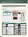
SV22 (Automatic Machinery Use)
Easy On-Screen Programming Using the Mechanical Support Language.
■ Incorporating a mechanical support language that allows easy programming of the mechanical system.
By combining a variety of software mechanical modules and Cam patterns, complex synchronized control and coordinated control can be
achieved easily and at low costs.
Ideal for controlling automatic machinery such as food processing and packaging.
Control flow
PLC CPU
Motion CPU
PLC program
Motion SFC program
SP.SFCS
......
K0
......
Virtual servomotor start
in the mechanical system program
Press conveyor
......
Drive module
Transmission module
[G200]
M2044 // On virtual mode?
Motion SFC
program start
request instruction
(Gear)
Servo program
[K 100 : Virtual]
1 VF
Axis 1,
Combine
Start program No. specification
Motion SFC program also can be automatically
started by the parameter setting.
(Clutch)
(Virtual servomotor)
#
0 PLS/s
Output
module
END
Positioning parameter
System setting
(Cam)
Operation results from the
transmission module are
output to the servo amplifier
set in the output module.
Fixed parameter
Servo parameter
Parameter block
(Roller)
Limit switch setting
Servo amplifier
Servo amplifier
Servomotor
Servomotor
Mechanical modules
Class
Mechanical Module
Name
Appearance
Function Description
Virtual
servomotor
• It is used to drive the virtual axis of mechanical system
program by the servo program or JOG operation.
Synchronous
encoder
• It is used to drive the virtual axis by the input pulses
from the external synchronous encoder.
Virtual main
shaft
• This is a virtual “link shaft”.
• Drive module rotation is transferred to the transmission
module.
Virtual
auxiliary
input axis
• This is the auxiliary input axis for input to the
differential gear of transmission module.
• It is automatically displayed when a differential gear
and gear are connected.
Gear
• The drive module rotation is transmitted to the output
axis.
• A setting gear ratio is applied to the travel value
(pulse) input from the drive module, and then transmits
to the output axis that it becomes in the setting rotation
direction.
Mechanical Module
Class
Name
Speed change
gear
Drive
module
Virtual
axis
Transmission
module
Direct clutch
Smoothing
clutch
23
• Transmit or separate the drive module rotation to the
output module.
• There are a direct clutch transmitted directly and the
smoothing clutch which performs the
acceleration/deceleration and transmission by the
smoothing time constant setting at the switching
ON/OFF of the clutch.
• It can be selected the ON/OFF mode, address mode or
the external input mode depending on the application.
• Time constant specified method or amount of slip
specified method can be selected as a smoothing
method.
Appearance
Function Description
• It is used to change speed of output module (roller).
• The setting speed change ratio is applied to input axis
speed, and transmits to the output axis.
• Auxiliary input axis rotation is subtracted from virtual
main shaft rotation and the result is transmitted to the
output axis.
Transmission
module
Differential
gear
• Auxiliary input axis rotation is subtracted from virtual
main shaft rotation, and the result is transmitted to the
output axis.
Roller
• It is used to perform the speed control at the final
output.
Ball screw
• It is used to perform the linear positioning control at
the final output.
Rotary table
• It is used to perform the angle control at the final
output.
Cam
• It is used to control except the above. Position control
is executed based on the Cam pattern setting data.
• There are 2 Cam control modes: the two-way Cam and
feed Cam.
Output
module
Mechanical support language
Realizing mechanical operation using software
Easy programming on screen using a mouse
By replacing the mechanical system of main shafts, gears,
clutches, and Cams with the software mechanical modules,
the following merits can be realized.
Machine is more compact and costs are lower.
There are no worries over friction and service life for the
main shaft, gear and clutch.
Changing initial setup is simple.
There is no error caused by mechanical precision, and system performance improves.
Advanced control using software Cam
Ideal Cam pattern control was achieved without problems,
such as an error produced in the conventional Cam control,
by processing the Cam control by software. The Cam control
for the nozzle lowering control in contact with liquid surfaces,
amount of filler control or smooth conveyance control, etc. can
be realized simply. Exchanging of Cam for product type
change is also possible easily by changing the Cam pattern
only.
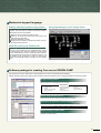
Programming monitor by mechanical support language
Software package for creating Cam curves SW3RN-CAMP
This package sets the Cam pattern when using software Cam control by mechanical support language.
Flexible and highly precise Cam patterns can be created to match the required control. Complex Cam patterns are easy to program.
11 types of Cam patterns
Whatever Cam curve you need can be created, by selecting and combinig Cam
patterns suited to your application among 11 types.
<Cam patterns>
• Constant-speed
• Cycloid
• Distorted constant-speed
• Single hypotenuse
• Constant-acceleration
• Distorted trapezoid
• Trapecloid
• Double hypotenuse
• 5th curve
• Distorted sine
• Reverse trapecloid
Can be set by free-form curves
Creating Cam pattern
Cam curves can be set by free curves using spline interpolation.
Selectable cam precision to match application
The resolution per cycle of Cam can be set in the following four stages.
• 256
• 512
• 1024
• 2048
Graphic display of control status
Control status information such as stroke ratio, speed and acceleration can be
displayed in simple graphics.
Graphic display of control state
24
SV22 (Automatic Machinery Use)
Application examples
Filling machine
Filling
Nozzle raised and lowered
Conveyance
Nozzle
Filling
Draw control
V
V+Draw
Press conveyance
Press machine
Main press motor
Die
Import conveyor
Synchronous
encoder
Export conveyor
Work
Work
X-axis servomotor
Y-axis servomotor
Three dimensional transfer
Lift (2)
Lift AC servomotor
Lift (1)
Lift AC servomotor
Feed
Feed
AC servomotor
Clamp (2)
Clamp
AC servomotor
Clamp (1)
25
Printing machine
Mark detection function
Synchronous operation between axes
Tandem operation
Torque control
Printing part
Processing part
(Note) : Consult individually about the case applied to a printing machine.
(It is necessary to use the operating system software, servo amplifiers and servomotors with special specification according to the system.)
Synchronous control
The servomotor can be operated by making it synchronous with other motor control conditions.
Synchronous operation with simple setting for synchronous control and little tracking delay can be realized by a mechanical support language.
A
T
B
3000r/min
Motor speed
Drive module
Transmission module
Gear
0.35˚
Position deviation
between 2-axes
0.13˚
Output module
(Virtual servomotor)
150.5ms
Roller
1-axis position deviation
2-axes position deviation
1-axis
Position deviation between axes
2-axes
Mechanical system program
Cam pattern switching control
The multiple Cam patterns can be operated
by switching for every work product type.
Changing initial work time can be shortened
sharply at the work product type change.
Cam pattern can be also switched per one
cycle, and it is applicable also to individual
production of multiple product types.
1-axis feed current value
2-axes feed current value
Cam pattern 1
Cam pattern 2
Cam pattern 3
26
Overview of CPU Performance
Motion control
Item
Q173CPUN
Q172CPUN
32 axes
8 axes
SV13
0.88ms : 1 to 8 axes
1.77ms : 9 to 16 axes
3.55ms : 17 to 32 axes
0.88ms : 1 to 8 axes
SV22
0.88ms : 1 to 4 axes
1.77ms : 5 to 12 axes
3.55ms : 13 to 24 axes
7.11ms : 25 to 32 axes
0.88ms : 1 to 4 axes
1.77ms : 5 to 8 axes
Number of control axes
Operation cycle (Note-1)
(default)
Interpolation functions
Linear interpolation (Up to 4 axes), Circular interpolation (2 axes), Helical interpolation (3 axes)
PTP (Point to Point), Speed control, Speed/position switching control, Fixed-pitch feed,
Constant-speed control, Position follow-up control, Speed switching control,
High-speed oscillation control, Synchronous control (SV22)
Control modes
Automatic trapezoidal acceleration/deceleration, S-curve acceleration/deceleration
Acceleration/deceleration control
Compensation function
Backlash compensation, Electronic gear
Programming language
Motion SFC, Dedicated instruction, Mechanical support language (SV22)
14k steps
Servo program (dedicated instruction) capacity
Number of positioning points
3200 points (Positioning data can be set indirectly)
IBM PC/AT
Programming tool
USB/RS-232/SSCNET
Peripheral I/F
Home position return function
Proximity dog type, Count type, Data set type (2 types)
Provided
JOG operation function
Possible to connect 3 modules
Manual pulse generator operation function
Synchronous encoder operation function
M-code function
Limit switch output function
Absolute position system
Number of Motion related modules
Possible to connect 12 modules (SV22 use)
Possible to connect 8 modules (SV22 use)
M-code output function provided, M-code completion wait function provided
Number of output points : 32 points
Watch data : Motion control data/Word device
Made compatible by setting battery to servo amplifier
(Possible to select the absolute/Incremental data method for each axis)
Q172LX : 4 modules
Q172EX : 6 modules
Q173PX : 4 modules (Note-2)
Q172LX : 1 module
Q172EX : 4 modules
Q173PX : 3 modules (Note-2)
(Note-1) : The operation cycle is 1.77ms or more when using the MR-H■BN.
(Note-2) : The incremental synchronous encoder use (SV22). When connecting the manual pulse generator, you can use only one module.
27
Mechanical system program (SV22)
Item
Drive module
Control unit
Output module
Drive module
Virtual axis
Mechanical system program
Transmission
module
Q173CPUN
Virtual servomotor
Synchronous encoder
Roller
Ball screw
Rotary table
Cam
Virtual servomotor
Synchronous encoder
Virtual main shaft
Virtual auxiliary input axis
Gear (Note-1)
Clutch (Note-1)
Speed change gear (Note-1)
Differential gear (Note-1)
PLS
mm, inch
32
12
32
32
Output module
Cam
Total 44
Total 64
Fixed as “degree”
mm, inch, PLS
8
8
8
8
Total 16
8
32
32
32
32
32
Total 16
16
16
16
8
64
64
64
32
Differential gear
(for the virtual main shaft) (Note-2)
Roller
Ball screw
Rotary table
Cam
Q172CPUN
Total 32
8
8
8
8
Total 8
Up to 256
256, 512, 1024, 2048
132k bytes
32767
Two-way Cam, feed Cam
Types
Resolution per cycle
Memory capacity
Stroke resolution
Control mode
(Note-1) : The gear, clutch, speed change gear or differential gear module can be used only one module per one output module.
(Note-2) : The differential gears connected to the virtual main shaft can be used only one module per one main shaft.
Motion SFC performance
Item
Program capacity
Motion SFC program
Q173CPUN/Q172CPUN
Code total (Motion SFC chart + Operation control +Transition)
Text total (Operation control + Transition)
Number of Motion SFC programs
Motion SFC chart size per program
Number of Motion SFC steps per program
Number of selective branches per branch
Number of parallel branches per branch
Parallel branch nesting
Number of operation control programs
Operation control
program (F/FS)
/
Transition program (G)
Number of transition programs
Code size per program
Number of blocks(line) per program
Number of characters per block
Number of operand per block
( ) nesting per block
Operation control program
Transition program
Number of multi executed programs
Number of multi active programs
Normal task
Descriptive
expression
Execute specification
Executed
task
Event task
(Execution can
be masked.)
NMI task
Number of I/O (X/Y) points
Number of real I/O (PX/PY) points
Internal relays
(M)
Latch relays
(L)
Link relays
(B)
Annunciators
(F)
Special relays
(M)
Number of devices
Data registers
(D)
Link registers
(W)
Special registers (D)
Motion registers (#)
Coasting timers (FT)
Fixed cycle
External interrupt
PLC interrupt
287k bytes
224k bytes
256 (No.0 to 255)
Up to 64k bytes (Included Motion SFC chart comments)
Up to 4094 steps
255
255
Up to 4 levels
4096 with F(Once execution type) and FS(Scan execution type) combined
(F/FS0 to F/FS4095)
4096 (G0 to G4095)
Up to approx. 64k bytes (32766 steps)
Up to 8192 blocks (4 steps (minimum) per block)
Up to 128 (Included comments)
Up to 64 (Operand: Constants, Word devices, Bit devices)
Up to 32
Calculation expression/Bit conditional expression
Calculation expression/Bit conditional expression/Comparison conditional expression
Up to 256
Up to 256 steps per all programs
Executed in motion main cycle
Executed in fixed cycle (0.88ms, 1.77ms, 3.55ms, 7.11ms, 14.2ms)
Executed when input ON is set among interrupt module (16 points)
Executed with interrupt from PLC CPU
Executed when input ON is set among interrupt module (16 points)
8192 points
256 points
Total (M + L) 8192 points
8192 points
2048 points
256 points
8192 points
8192 points
256 points
8192 points
1 point (888µs)
28
Overview of CPU Performance
Software packages
Software
Operating system software
Programming software
Model name
Q173CPUN
Q172CPUN
Application
Conveyor assembly use SV13
Automatic machinery use SV22
Conveyor assembly use SV13
Automatic machinery use SV22
Digital oscilloscope use
Note
SW6RN-SV13QB
SW6RN-SV13QD
SW6RN-SV22QA
SW6RN-SV22QC
SW6RN-GSV13P
SW6RN-GSV22P
SW3RN-CAMP
SW6RN-DOSCP
–
Included in the
"Integrated start-up
support software".
Integrated start-up support software packages MT Developer
Model name
SW6RN-GSVPROE
SW6RNC-GSVSETE
Details
SW6RNC-GSVE
(Integrated start-up support software)
[1 CD-ROM]
• Conveyor assembly software
• Automatic machinery software
• Cam data creation software
• Digital oscilloscope software
• Communication system software
• Document print software
: SW6RN-GSV13P
: SW6RN-GSV22P
: SW3RN-CAMP
: SW6RN-DOSCP
: SW6RN-SNETP
: SW3RN-DOCPRNP
SW20RN-DOCPRNP
SW6RNC-GSVHELPE (Operation manual [1 CD-ROM] )
Installation manual
SW6RNC-GSVPROE
A30CD-PCF (SSC I/F card (PCMCIA TYPE II 1CH/card) )
Q170CDCBL3M (A30CD-PCF cable 3m(9.84ft.) )
System component
<Motion dedicated equipments>
Part name
Motion CPU module
Servo external signals interface module
Serial absolute synchronous encoder
interface module
Manual pulse generator interface module
Serial absolute synchronous encoder
Serial absolute synchronous encoder cable
Dividing unit
Battery unit
Battery
Manual pulse generator
Model name
CE, UL
CE, UL
CE, UL
Q172EX
Serial absolute synchronous encoder MR-HENC interface✕2,Tracking input 2 points
CE, UL
Q173PX
MR-HENC
MR-JHSCBL ■ M-H, L
Q173DV
Q170BAT
MR-BAT/A6BAT
MR-HDP01
Q173HB▲CBL ■ M (Note-1)
Q173J2B▲CBL ■ M (Note-1)
Q173DVCBL ■ M
Manual pulse generator MR-HDP01/synchronous encoder interface✕3, Tracking input 3 points
CE, UL
Resolution: 16384PLS/rev, Permitted speed: 4300r/min
CE, UL
Serial absolute synchronous encoder ↔ Q172EX (When not using the tracking enable signal.)
–
For dividing SSCNET lines of Q173CPUN (Attachment: Battery holder for IC-RAM memory backup)
–
For IC-RAM memory backup of Motion CPU module
–
For backup of serial absolute synchronous encoder, for backup of external battery of Motion CPU module
–
Resolution: 25PLS/rev, Permitted speed: 200r/min, Open collector output
–
• Q173CPUN ↔ MR-H■BN
(Note-2)
• Q173CPUN ↔ MR-J2 ■-B
• Q173CPUN ↔ Q173DV
• Q172CPUN ↔ MR-H■BN
• MR-H■BN ↔ FR-V5NS (Note-3)
• Q172CPUN ↔ MR-H■BN and Q170BAT
• Q172CPUN ↔ MR-J2 ■-B (Note-2)
• MR-J2 ■-B (Note-2) ↔ FR-V5NS (Note-3)
Refer to the “SSCNET cable model” of
• Q173DV ↔ FR-V5NS (Note-3)
next page for cable length and details.
• Q172CPUN ↔ MR-J2 ■-B (Note-2) and Q170BAT
• Q172CPUN ↔ FR-V5NS (Note-3)
• FR-V5NS(Note-3) ↔ FR-V5NS (Note-3)
• MR-H■BN ↔ MR-H■BN
• MR-H■BN ↔ MR-J2 ■-B (Note-2)
• MR-H■BN ↔ Q173DV
• MR-J2 ■-B (Note-2) ↔ MR-J2 ■-B (Note-2)
• MR-J2 ■-B (Note-2) ↔ Q173DV
–
ISA bus loading _type, 2CH/board
_ 1CH/card
–
PCMCIA TYPE II,
–
For A30BD-PCF 3m (9.84ft.), 5m (16.4ft.), 10m (32.8ft.)
–
For A30CD-PCF 3m (9.84ft.), 5m (16.4ft.), 10m (32.8ft.)
(Note-1) ▲=Number of lines (none: 1 Line, 2: 2 Lines, 4: 4 Lines)
(Note-2) MR-J2 ■-B : MR-J2S-■B/MR-J2M-P8B/MR-J2-■B/MR-J2-03B5
(Note-3) SSCNET communication option for vector inverter FREQROL-V500 series (Coming soon!)
Q172HBCBL ■ M-B
Q172J2BCBL ■ M
Q172J2BCBL ■ M-B
FR-V5NSCBL ■
MR-HBUS ■ M
MR-J2HBUS ■ M-A
MR-J2HBUS ■ M
SSC I/F board
SSC I/F card
SSC I/F board cable
SSC I/F card cable
Standards
Up to 32 axes control, Operation cycle 0.88ms~
Up to 8 axes control, Operation cycle 0.88ms~
Servo external signal input 32 points (FLS, RLS, STOP, DOG/CHANGE✕8)
Q172HBCBL ■ M
SSCNET cable
Description
Q173CPUN
Q172CPUN
Q172LX
A30BD-PCF
A30CD-PCF
Q170BDCBL ■ M
Q170CDCBL ■ M
<PLC common equipments>
Part name
PLC CPU module
CPU base unit
Extension base unit
Extension cable
Power supply module
29
Model name
Q00CPU
Q01CPU
Q02CPU
Q02HCPU
Q06HCPU
Q12HCPU
Q25HCPU
Q33B
Q35B
Q38B
Q312B
Q63B
Q65B
Q68B
Q612B
QC■B
Q61P-A1
Q61P-A2
Q63P
Q64P
Description
Program capacity 8k
Program capacity 14k
Program capacity 28k
Program capacity 28k
Program capacity 60k
Program capacity 124k
Program capacity 252k
Power supply + CPU + 3 slots I/O modules, For Q series module
Power supply + CPU + 5 slots I/O modules, For Q series module
Power supply + CPU + 8 slots I/O modules, For Q series module
Power supply + CPU + 12 slots I/O modules, For Q series module
Power supply + 3 slots I/O modules, For Q series module
Power supply + 5 slots I/O modules, For Q series module
Power supply + 8 slots I/O modules, For Q series module
Power supply + 12 slots I/O modules, For Q series module
Length 0.45m(1.48ft.), 0.6m(1.97ft.), 1.2m(3.9ft.), 3m(9.8ft.), 5m(16.4ft.), 10m(32.8ft.)
100 to 120VAC input/5VDC 6A output
200 to 240VAC input/5VDC 6A output
24VDC Input/5VDC 6A output
100 to 120VAC/200 to 240VAC input/5VDC 8.5A output
Standards
CE, UL
CE, UL
CE, UL
CE, UL
CE, UL
CE, UL
CE, UL
CE, UL
CE, UL
CE, UL
CE, UL
CE, UL
CE, UL
CE, UL
CE, UL
–
CE, UL
CE, UL
CE, UL
CE, UL
SSCNET connecting methods
With Dividing unit
MODE
RUN
ERR
USER
BAT
BOOT
POWER
Without Dividing unit/External unit
MODE
RUN
ERR
USER
BAT
BOOT
MODE
RUN
ERR
USER
BAT
BOOT
POWER
MODE
RUN
ERR
USER
BAT
BOOT
Q173CPUN
PULL
Q173CPUN
PULL
PULL
USB
USB
RS-232
RS-232
PULL
PULL
USB
USB
RS-232
RS-232
PULL
SSCNET LINE 1
SSCNET LINE 1
CN1
CN1
Q
1
7
3
C
P
U
N
Dividing unit (Note-1)
(Q173DV)
CN1A
CN1B
Amplifier
CN1A
CN1B
CN1A
Amplifier
Amplifier
SSCNET LINE 2
CN1A
CN1B
Amplifier
CN1A
CN1B
CN1A
CN1B
Amplifier
SSCNET LINE 2
CN1B
CN1A
Amplifier
CN1B
Amplifier
CN1A
CN1B
Amplifier
(Note-1) When using the external battery, install the Battery (A6BAT/MR-BAT)
to the Dividing unit (Q173DV).
MODE
RUN
ERR
USER
BAT
BOOT
POWER
Q
1
7
2
C
P
U
N
MODE
RUN
ERR
USER
BAT
BOOT
MODE
RUN
ERR
USER
BAT
BOOT
POWER
MODE
RUN
ERR
USER
BAT
BOOT
Q172CPUN
PULL
PULL
Q172CPUN
PULL
PULL
USB
USB
RS-232
RS-232
PULL
CN1
PULL
USB
USB
RS-232
RS-232
CN1
CN1A
Battery unit (Note-2)
(Q170BAT)
CN1B
Amplifier
CN1A
CN1B
CN1A
Amplifier
CN1B
Amplifier
CN1A
CN1B
Amplifier
(Note-2) When using the external battery, install the Battery (A6BAT/MR-BAT)
to the Battery unit (Q170BAT).
SSCNET cable models
No.
Application
Q173CPUN ↔ Dividing unit
Q173CPUN ↔ Amplifier (Note-1)
Model name (Note-2)
Q173DVCBL■M
Q173J2B▲CBL■M (Note-3)
Q173HB▲CBL■M (Note-3)
Q172J2BCBL■M
Q172CPUN ↔ Amplifier
Q172HBCBL■M
FR-V5NSCBL■
Amplifier
Q172CPUN ↔
Battery unit
Cable length
0.5m(1.64ft.),1m(3.28ft.)
0.5m(1.64ft.),1m(3.28ft.),5m(16.4ft.)
0.5m(1.64ft.),1m(3.28ft.),5m(16.4ft.)
Amplifier ↔ Amplifier
Servo amplifier MR-J2■-B (Note-4)
• Q172CPUN ↔ Battery unit Q170BAT
Q172J2BCBL■M-B
0.5m(1.64ft.),1m(3.28ft.),5m(16.4ft.)
Q172HBCBL■M-B
Servo amplifier MR-H■BN
• Q172CPUN ↔
Battery unit Q170BAT
MR-J2HBUS■M
• Servo amplifier MR-J2■-B (Note-4) ↔ Servo amplifier MR-J2■-B (Note-4)
• Dividing unit Q173DV ↔ Servo amplifier MR-J2■-B (Note-4)
MR-HBUS■M
0.5m(1.64ft.),1m(3.28ft.),5m(16.4ft.)
Q172HBCBL■M
FR-V5NSCBL■
• Servo amplifier MR-H■BN ↔ Servo amplifier MR-J2■-B (Note-4)
• Dividing unit Q173DV ↔ Servo amplifier MR-H■BN
• Servo amplifier MR-H■BN ↔ Servo amplifier MR-H■BN
• Servo amplifier MR-J2■-B (Note-4) ↔ FR-V5NS (Note-5)
• Dividing unit Q173DV ↔ FR-V5NS (Note-5)
• Servo amplifier MR-H■BN ↔ FR-V5NS (Note-5)
Q172J2BCBL■M
Terminal connector
• Q173CPUN ↔ Servo amplifier MR-H■BN
• Q172CPUN ↔ Servo amplifier MR-J2■-B (Note-4)
• Q172CPUN ↔ Servo amplifier MR-H■BN
0.5m(1.64ft.),1m(3.28ft.),5m(16.4ft.),
• Q172CPUN ↔ FR-V5NS (Note-5)
10m(32.8ft.), 20m(65.6ft.)
MR-J2HBUS■M-A
Dividing unit ↔ Amplifier
Descriptions
• Q173CPUN ↔ Dividing unit Q173DV
• Q173CPUN ↔ Servo amplifier MR-J2■-B (Note-4)
0.5m(1.64ft.),1m(3.28ft.),5m(16.4ft.),
• FR-V5NS (Note-5) ↔ FR-V5NS (Note-5)
10m(32.8ft.), 20m(65.6ft.)
MR-TM
–
• Connect to the last servo amplifier MR-H■BN via SSCNET
MR-A-TM
–
• Connect to the last servo amplifier MR-J2-■B (Note-4) via SSCNET
(Note-1) : Branch from a connector on the Q173CPUN side according to the number of lines.
(Note-2) : ■=cable length 5m(16.4ft.) of cable length is indicated as “05” inside ■.
(Note-3) : ▲=SSCNET LINE No. (none(LINE1), 2(LINE1/2), 4(LINE1,2,3,4))
(Note-4) : MR-J2■-B : MR-J2S-■B/MR-J2M-P8B/MR-J2-■B/MR-J2-03B5
(Note-5) : SSCNET communication option for vector inverter FREQROL-V500 series(Coming soon!)
30
Combinations of Servo Amplifier and Servomotor
(As of Apr. 2003)
MR-J2M series
MR-J2M-
Servo amplifier
10DU
Servomotor
MR-J2-Super series
20DU
40DU
Motor
capacity
(kW)
MR-J2S70DU
10B
20B
40B
60B
70B
100B
200B
350B
500B
700B
HC-MFS053
Ultra low inertia,
Small capacity HC-MFS13
HC-MFS
HC-MFS23
3000r/min
HC-MFS43
series
HC-MFS73
0.05
HC-KFS053
Low inertia,
Small capacity HC-KFS13
HC-KFS
HC-KFS23
3000r/min
HC-KFS43
series
HC-KFS73
0.05
Low inertia,
Small capacity HC-KFS46
HC-KFS
Ultra high
velocity
HC-KFS410
motor series
Middle inertia, HC-SFS81
Middle capacity HC-SFS121
HC-SFS
HC-SFS201
1000r/min
series
HC-SFS301
0.1
0.2
0.4
0.75
0.1
0.2
0.4
0.75
0.4
0.4
0.85
1.2
2.0
3.0
HC-SFS52
0.5
HC-SFS102
1.0
Middle inertia,
Middle capacity HC-SFS152
HC-SFS
HC-SFS202
2000r/min
HC-SFS352
series
HC-SFS502
1.5
2.0
3.5
5.0
HC-SFS702
7.0
HC-SFS53
0.5
Middle inertia,
Middle capacity HC-SFS103
HC-SFS
HC-SFS153
3000r/min
HC-SFS203
series
HC-SFS353
HC-RFS103
Ultra low inertia,
Middle capacity HC-RFS153
HC-RFS
HC-RFS203
3000r/min
HC-RFS353
series
HC-RFS503
HC-UFS13
Flat,
Small capacity HC-UFS23
HC-UFS
HC-UFS43
3000r/min
series
HC-UFS73
HC-UFS72
Flat,
Middle capacity HC-UFS152
HC-UFS
HC-UFS202
2000r/min
HC-UFS352
series
HC-UFS502
HC-LFS52
Low inertia,
Middle capacity HC-LFS102
HC-LFS152
HC-LFS
2000r/min
HC-LFS202
series
HC-LFS302
1.0
1.5
2.0
3.5
1.0
1.5
2.0
3.5
5.0
0.1
0.2
0.4
0.75
0.75
1.5
2.0
3.5
5.0
0.5
1.0
1.5
2.0
3.0
: Special amplifier required
31
(As of Apr. 2003)
MR-J2-Super series
500B
Servomotor
700B
11KB
15KB
22KB
30KB
HA-LFS601
37KB4
45KB4
55KB4
8.0
12.0
HA-LFS15K1
15.0
HA-LFS20K1
20.0
HA-LFS25K1
25.0
HA-LFS30K1
30.0
HA-LFS37K1
37.0
HA-LFS30K14
30.0
HA-LFS37K14
37.0
7.0
HA-LFS11K1M
11.0
HA-LFS15K1M
15.0
HA-LFS22K1M
22.0
HA-LFS30K1M
30.0
HA-LFS37K1M
37.0
HA-LFS30K1M4
30.0
HA-LFS37K1M4
37.0
HA-LFS45K1M4
45.0
HA-LFS50K1M4
50.0
HA-LFS502
5.0
HA-LFS702
Low inertia,
Middle/large
capacity
HA-LFS
2000r/min
series
30KB4
HA-LFS12K1
HA-LFS701M
Low inertia,
Middle/large
capacity
HA-LFS
1500r/min
series
37KB
6.0
HA-LFS801
Low inertia,
Middle/large
capacity
HA-LFS
1000r/min
series
Motor
capacity
(kW)
MR-J2S-
Servo amplifier
7.0
HA-LFS11K2
11.0
HA-LFS15K2
15.0
HA-LFS22K2
22.0
HA-LFS30K2
30.0
HA-LFS37K2
37.0
HA-LFS30K24
30.0
HA-LFS37K24
37.0
HA-LFS45K24
45.0
HA-LFS55K24
55.0
(As of Apr. 2003)
MR-J2-Jr series
Servo amplifier
Servomotor
Compact size, HC-AQ0135D
Small capacity
HC-AQ0235D
HC-AQ
series
HC-AQ0335D
MR-J2-
Motor
capacity
(kW)
03B5
0.01
0.02
0.03
An absolute system is not available for the MR-J2B-03B5.
32
Exterior Dimensions
CPU module Q173CPUN
CPU module Q172CPUN
MODE
RUN
ERR.
M.RUN
BAT.
BOOT
MODE
RUN
ERR.
M.RUN
BAT.
BOOT
CN1
98(3.86)
CN2
PULL
FRONT
SSCNET
98(3.86)
FRONT
SSCNET
CN2
PULL
CN1
USB
USB
RS-232
RS-232
4.5(0.18)
4.5(0.18)
27.4(1.08)
27.4(1.08)
114.3(4.50)
114.3(4.50)
[Unit : mm (inch)]
[Unit : mm (inch)]
Servo external signals interface module Q172LX
Serial absolute synchronous encoder interface module Q172EX
CTRL
98(3.86)
98(3.86)
SY.ENC1
SY.ENC2
Q172EX
Q172LX
27.4(1.08)
90(3.14)
27.4(1.08)
90(3.14)
[Unit : mm (inch)]
[Unit : mm (inch)]
Manual pulse generator interface module Q173PX
Mounting
Top of control panel, wiring duct, or
other components
Base unit
(Note-2)
30mm
(1.18 inch)
or more
Control
panel
98(3.86)
PULSER
Motion CPU module
(Note-1)
Q173PX
Door
100mm
(3.94 inch)
or more
100mm
(3.94 inch)
or more
5mm
(0.19 inch)
or more
27.4(1.08)
Motion
controller
5mm
(0.19 inch)
or more
(Note-1) : 20mm(0.79 inch) or more when without removing the adjacent module.
(Note-2) : 40mm(1.58 inch) or more when the height of a wiring duct is 50mm
(1.97 inch) or more.
90(3.14)
[Unit : mm (inch)]
Base unit Q3
B/Q6
B
4-fixing screw (M4 ✕ 14)
CPU base
Extension base
Q35B Q38B Q312B Q65B Q68B Q612B
5V
W
245
328
439
245
328
439
(9.65) (12.92) (17.30) (9.65) (12.92) (17.30)
Ws
224.5 308
419 222.5 306
417
(8.85) (12.14) (16.51) (8.77) (12.06) (16.43)
H
98(3.86)
Hs
80(3.16)
POWER
I/00
I/01
I/02
I/03
I/04
Ws
W
33
I/05
I/06
I/07
I/08
I/09
I/10
I/11
H
CPU
F6
Hs
56
[Unit : mm (inch)]
φ15(0.59) -0.006
-0.017
B
Specifications
Resolution
16384PLS/rev
Direction on increase
Counter clockwise (viewed from end of axis)
Protective construction IP52
φ50(1.97)-0.009
-0.025
φ68(2.68)
Item
56(2.2)
56(2.2)
N.P
B
68(2.68)
68(2.68)
0
φ14.3(0.56)-0.11
0
φ14.3(0.56)-0.11
φ16(0.63)
φ67(2.64)
Serial absolute synchronous encoder MR-HENC
Permitted axis load
Radial : Up to 98N
Thrust : Up to 49N
Permissible rotation speed 4300r/min
Permissible angular acceleration 40000rad/s2
1.15(0.05) +0.14
0
2(0.08)
20(0.79)
1.15(0.05)
2(0.08)
5(0.2)
102(4.2)
28(1.1)
3(0.12)
33(1.3)
19.5(0.77)
Operating temperature -5 to 55°C (23 to 131°F)
4-φ5.4(0.21)
91(3.58)
20(0.79) Effective dimension
21(0.83)
+0.14
0
5(0.2) -0.012
-0.042
5VDC consumption current 0.15A
Weight
1.5kg
3(0.12) +0.1
0
135(5.31)
Shaft cross-section
Cross-section B-B
Keyway Dimensional Diagram
[Unit : mm (inch)]
Manual pulse generator MR-HDP01
3.6(0.14)
0
φ60(2.36)±0.5
φ80(3.15)±1
φ70(2.76)
φ50(1.97)
20
70
30
80
+5~
12V 0V A B
60
50
16
20
(0.63) (0.79)
Specifications
Pulse resolution
25PLS/rev (100PLS/rev at magnification of 4)
Output voltage
Input voltage > -1V (Note)
Life
More then 1,000,000 revolutions at 200r/min
Permitted axis load
27.0±0.5
8.89
7.6
(1.06)
(0.35)
(0.3)
Weight
0
4) _+2
0.4kg
(Note) : When using an external power supply, necessary to 5V
power supply.
3) ±0.2
Battery unit Q170BAT
2-φ5.3 (Fixing screw M5✕14)
7.5
40(1.57)
(0.29)
7.5(0.29)
[Unit : mm (inch)]
10
10
19.5
80(3.15)
(0.39) (0.80)
125(4.92)
140(5.51)
16.5
45(1.77)
60(2.36)
45(1.77)
4-φ5.3 (Fixing screw M5✕14)
60(2.36)
Dividing unit Q173DV
(0.39) (0.65)
40
(2.4
Thrust : Up to 9.8N
5VDC consumption current 0.06A
[Unit : mm (inch)]
φ62
Radial : Up to 19.6N
Operating temperature -10 to 60°C (14 to 140°F)
M3✕6
3-φ4.8(0 to 19)dia.,
equi-spaced
φ72(2
.8
Item
3-Studs (M4✕10)
PCD72,equi-spqced
NP
90
10
Packing t=2.0
[Unit : mm (inch)]
34
For safe use
• To use the products given in this catalog properly, always read the “manuals” before
starting to use them.
• This product has been manufactured as a general-purpose part for general industries,
and has not been designed or manufactured to be incorporated in a device or system
used in purposes related to human life.
• Before using the product for special purposes such as nuclear power, electric power,
aerospace, medicine or passenger movement vehicles, consult with Mitsubishi.
• This product has been manufactured under strict quality control. However, when
installing the product where major accidents or losses could occur if the product fails,
install appropriate backup or failsafe functions in the system.
Precautions for Choosing the Products
Mitsubishi will not be held liable for damage caused by factors found not to be the cause
of Mitsubishi; machine damage or lost profits caused by faults in the Mitsubishi products;
damage, secondary damage, accident compensation caused by special factors
unpredictable by Mitsubishi; damages to products other than Mitsubishi products; and to
other duties.
HEAD OFFICE : MITSUBISHI DENKI BLDG., 2-2-3, MARUNOUCHI, CHIYODA-KU, TOKYO 100-8310, JAPAN
L(NA)03014-B 0305 Printed in Japan <MDOC>
New publication, effective May. 2003
Specifications subject to change without notice.