1
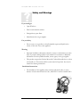
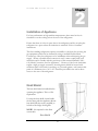
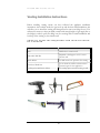
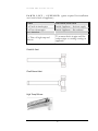
UNIQUE UGP-6C/8C/10C DV DIRECT VENT REFRIGERATOR (Balanced Flue System) Installation and Owner’s Manual WARNING: Improper installation, adjustment, alteration, service or maintenance can cause injury or property damage. Refer to this manual. For assistance or additional information consult a qualified installer, service agency or the gas supplier. !SAVE THESE INSTRUCTIONS! FOR YOUR SAFETY IF YOU SMELL GAS Open windows. Do not touch electrical switches. Extinguish any open flame Immediately turn off gas supply and call your gas supplier FOR YOUR SAFETY Do not store or use gasoline or other flammable and liquids in the vicinity of this or any other appliance The installation of the appliance must conform with local codes or, in the absence of local national Fuel Gas Code, ANSI Z233.1 and in Canada B149.2 Propane Storage and Handling Code June, 2012 CERTIFIED AND DISTRIBUTED BY Unique Gas Products Ltd ““PPeerrssoonnaall SSeerrvviiccee & & KKnnoow maakkeess uuss U wlleeddggee m Unniiqquuee”” 2245 Wyecroft Road #5 Oakville, Ontario Canada L6L 5L7 Ph: 905-827-6154 Toll Free: 1-877-427-2266 Fax: 905-827-2027 www.UniqueOffGrid.com E-mail: [email protected] Table of Contents Chapters Welcome 1 Safety and Warnings 1 Appliance, Heat Shield, & Venting Installation Instructions 2 General Operating Instructions 3 How to Use The Refrigerator 3 Maintenance & Service 4 Troubleshooting & Suggested Spares 5 Door Removal and Reversal 6 Temperature Controls, Food Storage and Cleaning 7 Parts List (incl. venting components) & Warranty 8 Note: It is unsafe to operate your fridge without the supplied venting attached to the appliance due to the chance of Carbon Monoxide poisoning. U N I Q U E U G P 6 C / 8 C / 1 0 C 1 Chapter D V Welcome & Congratulations C ongratulations on your purchase of a UNQIUE refrigerator!. We are very proud of our product and we are completely committed to providing you with the best service possible. Your satisfaction is our #1 priority. Please read this manual very carefully. It contains valuable information on how to properly maintain your new gas refrigerator. We know you will enjoy your new refrigerator and Thank You for choosing one of our Unique Gas Products. We hope you will consider us for future purchases. PLEASE READ AND SAVE THESE INSTRUCTIONS This manual provides specific operation instructions for your model. Use your refrigerator only as instructed in this manual. These instructions are not meant to cover every possible condition and situation that may occur. Common sense and caution must be practiced when installing, operating and maintaining the appliance Please record your model and serial # shown below for future reference. This information is found on your CSA rating/serial plate inside the refrigerator compartment. Please mail in the Warranty Registration Card included with you refrigerator. 1 U N I Q U E U G P 6 C / 8 C / 1 0 C D V Safety and Warnings If you smell gas Open Windows Don’t touch electrical switches Extinguish any open flame Immediately call your gas supplier For you Safety Do not store or use gasoline or other flammable vapors and liquids in the vicinity of this unit or any other appliance Warning Improper installation, adjustment, alteration, service or maintenance can cause injury or property damage. Refer to this manual. For assistance or additional information consult a qualified installer, service agency or the gas supplier. This product can produce Carbon Monoxide. Carbon Monoxide has no odour and can kill you. The burner and flue system must be kept clean. See owner’s manual for cleaning instructions. Installation Instructions The installation of the appliance must conform with local codes or, in the absence of local national Fuel Gas Code, ANSI Z233.1 and in Canada B149.2 2 U N I Q U E U G P 6 C / 8 C / 1 0 C 2 Chapter D V Installation of Appliance For best performance at high ambient temperatures, there must be free air circulation over the cooling unit at the rear of the refrigerator. Ensure that there is a free air space above the refrigerator and do not place the refrigerator in a space where air circulation is restricted. Follow “clearance” instructions. This free-standing refrigerator requires accessibility to the back for servicing the gas equipment, which can be obtained by using a certified Flexible Metal Connector to allow the refrigerator to be withdrawn without disrupting the gas supply. “Where a flexible metal connector is used, it must comply with local authorities and in Canada with the provisions of the current Standard CAN 16.10, Metal Connectors for Gas Appliances”. However, if the Local Authorities require a rigid gas supply connector, the refrigerator should be located with sufficient space at the back for servicing or, if located against a wall a removable panel of a minimum size of 16” x 20” should be provided in the wall to allow access to the rear of the refrigerator. Heat Shield The heat shield must be installed before operating the appliance. This is a CSA requirement. Un-wrap the heat shield (located inside the box along with the appliance). Mount heat shield with the screws (supplied) to left side of the fridge. See diagram. NOTE: Not required on the direct vent models Heat Shield 3 U N I Q U E U G P 6 C / 8 C / 1 0 C D V Clearances Minimum clearances to combustible materials are: Top – 6” Sides – 2” Rear – 1” as shown in Figures. 1, 2 & 3. Note: DO NOT install the appliance directly on carpeting. Carpeting must be removed or protected by a metal or wood panel beneath the appliance, which extends at least the full width and depth of the appliance Air Flow - to release heat trap Fig#1 - This is ideal as both top and sides are open Fig#2 – During hot/humid weather this confined area will become very warm. To reduce heat build-up, we recommend providing an area for two air vents to circulate the air. One placed 6” off the floor and the other at or above the appliance top. Cold air return vents with adjustable louvers, works very well. This will allow hot air to evacuate the area and assist in air flow across the fins (similar to air passing across a radiator) – See Fig #4 Fig#3 – If this is your opening you only need to stay the diagrammed distance from the wall and ceiling. There is no need for additional circulation. Gas Connection Hook-up to the gas supply line: 3/8” SAE (UNF 5/8” - 18) male flare connection. A backup wrench must be used when tightening gas supply fitting. All completed 4 U N I Q U E U G P 6 C / 8 C / 1 0 C D V connections should be checked for leaks with a non-corrosive leak detector and/or soap and water for a bubble check. WARNING – DO NOT USE FLAME TO CHECK FOR GAS LEAKS The gas supply system must incorporate a pressure regulator to maintain a supply pressure of not more than 12” water column and no less than 11” water column. (max setting) Make sure the refrigerator and any other high BTU appliances on your line are turned on when checking the gas pressure. The appliance and its individual shut-off valve must be disconnected from the gas supply piping system during any pressure testing of that system at pressures in excess of ½” psig. In case detailed instructions on the installation and connection of the gas supply are required, contact your dealer or distributor. Leveling Ensure the fridge is level by using a 2ft level. Level the fridge front to back and left to right using the top of the appliance. There are no leveling legs at the back of the appliance just at the front; if the back if your floor is uneven you will have to use shims of some sort to ensure the appliance is level. See the importance of leveling in Chapter 3. 5 U N I Q U E U G P 6 C / 8 C / 1 0 C D V Venting Installation Instructions Before installing venting ensure you have followed the appliance installation instructions above which entails the gas hook up and the heat shield installation, this will allow you to install the venting and then proceed to start your fridge for use. You will need to ensure you have provided yourself with enough length of gas supply line to the fridge in order to pull your fridge out for servicing and for initial installation and hook up of the venting to your interior wall. TOOLS & SUPPLIES REQUIRED FOR INSTALLATION OF VENTING TOOLS APPLICATION Drill Drill holes in exterior wall Adjustable Drill Bit Required to drill approx 2.375” hole in exterior wall Small drill bit To drill center hole positions for venting Hack Saw/Hand Saw To cut fresh air and flue exhaust tube to custom length for the application Caulking Gun & Silicone Sealant For sealing spaces around venting in wall 6 U N I Q U E U G P 6 C / 8 C / 1 0 C D V P A R T S L I S T - S U P P L I E D ( parts required for installation are found at back of appliance) PARTS LOCATION/FUNCTION 1 x Fresh air intake pipe 1 x Flue exhaust pipe Inside Appliance – fresh air supply Inside Appliance – flue exhaust POLY PARTS BAG 1 x Tube of high temp red silicone To connect fresh air pipe and flue exhaust pipe to existing venting on appliance Fresh Air Vent Flue Exhaust Vent High Temp Silicone 7 U N I Q U E U G P 6 C / 8 C / 1 0 C D V Fresh Air and Flue Exhaust Vent Location & Assembly If not already done so locate the fresh air vent, flue exhaust vent and poly bag containing high temp silicone from the back of the appliance and set aside. Decide where the fridge is to be located, it must be against an exterior wall keeping in mind that included with the fridge there is 19" of available venting from the exterior wall to the back of fridge. (can be cut down to fit application) It's best to keep the location of the appliance as close as possible to the interior wall for optimal operation. The next step will determine where the holes are to be drilled to accommodate the fresh air and flue exhaust vents. Slide your fridge close as possible to the interior wall, now mark the bottom position of the fresh air vent tube that is attached to the fridge on your inner wall, also mark the top position with a pencil. Once you have done this go ahead and do the same for the flue exhaust pipe. Note: the flue exhaust tube could be a slightly different height. Make sure you have leveled your fridge before the next step After both the fresh air and flue exhaust vents have been marked on your interior wall, next find the center of each and mark. For the flue exhaust increase the height of the center marking approx 3/8” this will allow the flue exhaust tube to be on a slight angle upwards once installed. See Figure A on next page. 8 U N I Q U E U G P 6 C / 8 C / 1 0 C D V Figure A Now prepare to drill holes in the interior wall for each the fresh air and flue exhaust tube. Depending on what’s on your outside wall you will have to make necessary adjustments in the drilling process. Take your adjustable drill bit or similar tool and set it to a diameter of approx 2.375” which is the outer diameter of the venting. We suggest you make it slightly larger to allow for thicker/deeper walls, this will allow for a littlie play if you do not have it lined up just right where measurements are not exact. The extra space can be filled in with silicone afterwards. You now have your holes in the wall, the next step is to take each the fresh air vent and flue exhaust vent and push them through from the exterior wall inward. Make sure the long part of the “T” on the flue exhaust vent, faces down – see below Long Part Down Flue Exhaust Vent 9 U N I Q U E U G P 6 C / 8 C / 1 0 C D V Note: Both the fresh air and flue exhaust vent can be cut down so that the fridge can be pushed as close as possible to the interior wall being mindful of the allowable clearances. The fridge comes with enough venting to vent your fridge 19” from the exterior wall to the back of your fridge. In high wind situations the shorter you make the vents, the increased chance the fridge will shut down. An alternative solution will be a vent shroud available through Unique Push your fridge up against the interior wall to meet both the fresh air and the flue exhaust vent that you have just pushed through, temporally connect them to the fridge in order to determine what length you need to cut off, if any. Figure B 10 U N I Q U E U G P 6 C / 8 C / 1 0 C D V In order to determine what lengths you need to cut off measure from the inside wall to the back of your fridge. We suggest allowing 1” for clearance between the back of the fridge and the interior wall, therefore cut the fresh air and the flue exhaust vent with suggested tools allowing for a 1” to 2” protrusion or more through the interior wall into the room and a minimum 1” space from the exterior wall to the flange connection. Note: You will find that on the flue exhaust tube there is a slight protrusion of the aluminum interior vent tube; this allows you the ability to connect it to the fridges chimney, ensure you maintain this protrusion when cutting your flue exhaust tube. Please be aware the venting does not have to be cut down, it will operate with the supplied vent lengths. Only cut down the lengths if the venting will protrude too far out from the exterior wall and will be in the way of a walkway, etc where someone may bump into them. In high wind situations the shorter you make the vents, the increased chance the fridge will shut down. CONNECTING VENTING TO FRIDGE After cutting your tubes to the required length for your application, push your fridge up to the fresh air and flue exhaust tube, they will fit into the venting connections on the fridge. Take the high temp silicone and apply a ¼” bead around both the outside of the fresh air and the flue exhaust vents or the inside of the venting that’s attached to the fridge, either way you want to ensure an air tight fit once they are joined together. See Figure C on next page. For the flue exhaust once you have joined the connection you can pull the black insulation from the chimney bend over the connection to cover it, this will ensure it’s well insulated. 11 U N I Q U E U G P 6 C / 8 C / 1 0 C D V Figure C Sealing the fresh air and flue exhaust tubes at interior and exterior wall You now need to seal the inside and exterior spaces surrounding both the fresh air tube and flue exhaust. See figure D below on next page. 12 U N I Q U E U G P 6 C / 8 C / 1 0 C D V Figure D Venting installation is now complete, you now can move onto General Operating Instructions – Chapter 3 13 U N I Q U E U G P 6 C / 8 C / 1 0 C 3 Chapter D V General Operating Instructions Importance of Leveling a Refrigerator The refrigerator must be adjusted to a vertical position in both directions. In an absorption refrigeration system, ammonia is liquefied in the finned condenser coil at the top rear of the refrigerator. The liquid ammonia then flows into the evaporator (inside the freezer section) and is exposed to circulating flow of hydrogen gas, which causes the ammonia to evaporate, creating a cold condition in the freezer. When starting this refrigerator for the very first time, the cooling cycle may require up to 4 to 6 hours of running time before the cooling unit is fully operational to begin slowly loading compartment with cold food from your cooler. The tubing in the evaporator section is specifically sloped to provide a continuous movement of liquid ammonia, flowing downward by gravity through this section. If the refrigerator is operated when not level, liquid ammonia will accumulate in sections of the evaporator tubing. This will slow the circulation of hydrogen and ammonia gas, or in severe cases, completely block it, resulting in a loss of cooling. Warranty will not cover recharge/rebuild if caused by not running the fridge level. This refrigerator operates on LP Gas (Propane) & 110V (Electricity) Note: After changing an LP tank, or after a long shut off period, the gas line is likely to be filled with air. You may have to repeat the lighting procedure several times to purge the air out of the gas lines. We suggest first turning off gas at the control panel, then the tank, this will reduce an air trap in the gas line. Gas Operation – for models with both piezo or electronic ignition “Start Up” Procedure – see Figure #5 Piezo Ignition 1. To start the refrigerator, turn the thermostat knob E to maximum setting, fully clockwise. 14 U N I Q U E U G P 6 C / 8 C / 1 0 C D V 2. Turn button G to Gas position, push button B repeatedly before you press in and hold D button, continue to hold in the D button and repeatedly press the B button until you see that the needle on the flame sensor C has moved from the white into the green area. The burner should now be “on”, if not repeat the lighting instructions above. Once in green zone for 15-30 seconds, release D button. 3. It is important that you start sparking first before pressing in the gas button, otherwise you may flood the burner box with gas, if this happens it will not light and you will have to wait a period of time for the gas to dissipate before starting the process again. 4. Adjust the thermostat knob to desired temperature setting after 4 to 6 hours of operation. Electronic Ignition (battery) 1. To start the refrigerator, turn the thermostat knob E to maximum setting, fully clockwise. 2. Turn button G to Gas position, push and hold button B before you press in and hold D button, continue to hold in D & B buttons until you see that the needle on the flame sensor C has moved from the white into the green area. The burner should now be “on”, if not repeat the lighting instructions above. Once in green zone for 15-30 seconds, release both B &D buttons. 3. It is important that you start sparking first before pressing in the gas button, otherwise you may flood the burner box with gas, if this happens it will not light and you will have to wait a period of time for the gas to dissipate before starting the process again. 4. Adjust the thermostat knob to desired temperature setting after 4 to 6 hours of operation. 5. To change the batteries in the electronic ignition button to the left to expose the battery, remove AA battery and replace with new one, replace the knob and turn the to the right to close. 15 U N I Q U E U G P 6 C / 8 C / 1 0 C D V Shut Down Procedure – Gas Operation 1. Turn selector knob G to the OFF position 2. Shut the gas off at the LP-gas supply cylinder when the appliance is not in use. 3. If the refrigerator will not be in operation for a period of weeks, it should be emptied, defrosted, cleaned and the doors left open. 110V Operation 1. Ensure the electrical cord is plugged into a grounded outlet 2. Turn the selector switch G to AC position, AC power indicator F will illuminate 3. To start the refrigerator, turn the thermostat knob E to maximum setting. 4. Adjust the thermostat knob to desired temperature setting after 4 to 8 hours of operation. Note: If ignition does not occur immediately while lighting the refrigerator, you have flooded the burner box, wait 5 to 10 minutes and repeat. This time will allow the propane to dissipate then repeat the lighting process again. The fridge must not run with any of its venting disconnected or with burner box cover removed, except for servicing/testing the unit. Doing this will cause a danger of carbon monoxide entering the room. CONTROLS – See Fig 5. for description of controls Figure 5 Off A B C D E 16 F G U N I Q U E U G P 6 C / 8 C / 1 0 C D V Thermostat The refrigerator cooling temperature is controlled by a combination thermostat that can be adjusted by turning knob E to different settings to maintain the desired refrigerator temperature. It also incorporates a safety device which automatically shuts off the supply of gas if the flame goes out. The piezo electric igniter and/or the electronic ignition discharges sparks onto the burner when the appropriate button is pushed. See Figure #5 1. “MIN” Setting on the Gas Thermostat: In gas operation, the thermostat closes its main valve and the burner runs continuously at the bypass rate or pilot flame. (counter clockwise turn) 2. “MAX” Setting of the Thermostat: In gas operation, the thermostat allows the burner to remain on high flame continuously. (Clockwise turn) 3. The thermostat can be adjusted between “Max” and “Min” (4 or 1) to obtain the desired fridge temperature. When the thermostat reaches the set temperature, it will cut the burner back to bypass operation. The setting of the thermostat is critical and recommend it be adjusted to maintain a dry frost on the cooling fins (approx 38 Ferinheight or 3 Celsius). Adjust the thermostat knob closer to “Max” (clockwise) when the outside temperature rises. NOTE: When first turning refrigerator on, move refrigerator controls to maximum, which is the recommended initial setting. After 24 hours, adjust the controls as needed. How To Use The Refrigerator FOOD STORAGE COMPARTMENT The food storage compartment is completely closed and unventilated, this is necessary to maintain the required low temperature for food storage. The coldest areas in the refrigerator are under the cooling fins and at the bottom of the refrigerator. The warmer areas are on the upper door shelves. This should be considered when placing different types of food in the refrigerator. 17 U N I Q U E U G P 6 C / 8 C / 1 0 C D V FROZEN FOOD STORAGE COMPARTMENT Quick freeze soft fruits and ice cream should be placed in the coldest part of the compartment which is at the bottom of the aluminum liner. Frozen vegetables, may be stored in any part of the compartment. This compartment is not designed for deep or quick freezing of food. Meat or fish, whether raw or prepared, can be stored in the frozen food storage compartment provided they are pre-cooled in the refrigerator. To prevent food from drying out, keep it in covered dishes, containers, plastic bags or wrapped in aluminum foil. How To Use The Refrigerator FOOD STORAGE COMPARTMENT The food storage compartment is completely closed and unventilated, which is necessary to maintain the required low temperature for food storage. The coldest areas in the refrigerator are under the cooling fins and at the bottom of the refrigerator. The warmer areas are on the upper door shelves. This should be considered when placing different types of food in the refrigerator. FROZEN FOOD STORAGE COMPARTMENT Quick frozen soft fruits and ice cream should be placed in the coldest part of the compartment which is at the bottom. Frozen vegetables, may be stored in any part of the compartment. This compartment is not designed for deep or quick freezing of food. Meat or fish, whether raw or prepared, can be stored in the frozen food storage compartment provided they are pre-cooled in the refrigerator. To prevent food from drying out, keep it in covered dishes, containers, plastic bags or wrapped in aluminum foil. Defrosting Frost will gradually accumulate inside the refrigerator and freezer surfaces. It must not be not allowed to grow too thick as it acts as an insulator and adversely affects the refrigerator performance. Check the formation of frost every couple of weeks and when it exceeds 1/2” thick or more defrost the refrigerator. Shut off and empty the refrigerator, leaving the fridge and the freezer doors open. Defrosting time can be reduced by filling the ice tray with hot water and placing it in the freezer compartment. You can also open the doors without shutting off the appliance to defrost the fridge; the process will just be a bit slower. 18 U N I Q U E U G P 6 C / 8 C / 1 0 C D V DO NOT USE A HOT AIR BLOWER, PERMANENT DAMAGE COULD RESULT , DO NOT USE A KNIFE, AN ICE PICK, OR ANY OTHER SHARP TOOLS TO REMOVE FROST FROM THE FREEZER COMPARTMENT. FRIDGE SECTION Inside the refrigerator compartment, the defrost water runs from a collector channel to a drip tray/cup at the rear of the refrigerator where it normally evaporates. If heavy frost has built up on the cooling fins creating a lot of defrost water, Beware your water reservoir may overflow, we suggest you inspect reservoir before/after cycle. FREEZER SECTION This area must be wiped down with cloths to remove water after defrosting; there is no drain for this compartment When all frost is melted in the freezer compartment & interior of the refrigerator it should be wiped up with a clean cloth. Replace all food and set the thermostat to your desired setting. Cleaning Cleaning the refrigerator is usually done after it is defrosted or put into storage. To clean the interior liner of the refrigerator, use lukewarm weak soda solution. Use only warm water to clean the finned evaporator, gasket, ice trays and shelves. Never use strong chemicals or abrasives to clean these parts as the protective surfaces will be damaged. It is important to always keep the refrigerator clean. Dishwasher detergent is recommended Inside Light The interior light turns on when the door is open. The light uses four AA batteries located at the back of the appliance. To change the batteries, use the following procedure: 1. Go to the back of the appliance and remove the cover held in place by 4 Phillips screws 2. Remove and replace the 4 x AA batteries 19 U N I Q U E U G P 6 C / 8 C / 1 0 C D V 3. Replace the cover and 4 Phillips if present 4. The light will come on when the fridge door is open, and will shut off when the fridge door is closed by a switch located at the upper right hand side of the inner portion of the fridge. You can check its operation by manually pressing and releasing the switch. Shut Down Procedure A. Turn gas valve knob to the “off” position B. If the refrigerator will not be in operation for a period of weeks, it should be emptied, defrosted, cleaned and the doors left open. The ice tray should also be dried and kept outside the cabinet, also turn off gas at the main supply source. 20 U N I Q U E U G P 6 C / 8 C / 1 0 C 4 Chapter D V Maintenance & Service The user should be aware of service that must be done on a regular schedule to keep the refrigerator operating properly. Installation must be by a licensed gas fitter in accordance with local codes or in the absence of local national Fuel Gas Code, ANSI Z233.1 and in Canada B149.2 Propane Storage and Handling Code (latest edition). REFRIGERATOR REMOVAL and PERIODIC MAINTENANCE Before working on the refrigerator, shut off the gas supply. Disconnect the gas supply line at the rear of the refrigerator. Always use a back up wrench when loosening and tightening this connection. Cap the gas supply line and remove the refrigerator. Replacement is the reverse of removal. Check all connections for gas leaks. Refer to Chapter 2 - Installation To keep your refrigerator operating effectively and safely, periodic inspection and cleaning of several components is recommended once or twice a year, sometimes more often depending on environment. It's important to keep the area at the back of the refrigerator clean. Clean the coils on the back of the refrigerator. Use a soft bristled brush to dust off the coils. Note: The following maintenance is required at least once or twice a year at least. Check all connectors in the complete refrigerator LP gas system for gas leaks. The LP gas supply must be turned on. Apply a non corrosive bubble solution to all LP connections. The appearance of bubbles indicates a leak and should be repaired immediately by a qualified serviceman. WARNING – DO NOT USE FLAME TO CHECK FOR GAS LEAKS 21 U N I Q U E U G P 6 C / 8 C / 1 0 C D V Check burner flame for proper appearance. The flame should be light blue with no yellow at the tip. See figure #6 Fig. #6 Fig. #7 Burner Mounting Screw Burner Jet/Orifice The LP gas pressure should be checked and the main regulator readjusted if pressure is incorrect. The correct operating pressure is 11” W.C. (water column). Inspect the flue baffle, it should be clean and free of soot. Any soot formation indicates improper functioning of the burner. The flue and burner both require cleaning in the following manner: o Remove cover from the burner housing. o Remove the burner by removing the burner mounting screw o Remove the wire and flue baffle from the top of flue tube. Clean the flue from the top using a flue brush and be sure to cover the burner if remaining intact to eliminate dirt falling into burner. Blowing compressed air into the flue should clean out soot and scale. Replace the flue baffle. o Clean burner tube with compressed air, check for fluff or spider webs. o Before removing burner orifice, clean burner area of any soot, scale or dirt. Remove the orifice/burner jet and soak it in alcohol (isopropyl alcohol or thinners) and blow it out with compressed air. Re-install and tighten burner orifice. o Replace burner 22 U N I Q U E U G P 6 C / 8 C / 1 0 C D V Warning - DO NOT use a pin or wire when cleaning the burner orifice as damage can occur to the precision opening. This can cause damage to the refrigerator or create a fire hazard. It will also create extremely dangerous levels of carbon monoxide. o The inlet & outlet gas fittings on the refrigerator need to be checked for leaks. Apply a non corrosive bubble solution to the fittings and observe for leaks. The safety valve will not allow gas pressure to any connections between it and the burner orifice. These fittings must be checked while burner is in operation (gas flow will be present between safety valve and burner head) WARNING – The gas button D Fig#5 must be manually depressed to allow gas pressure to flow to the burner orifice. Be sure to apply the leak check solution before depressing the safety shut–off. DO NOT allow any open flame, sparks, smoking, etc. in the area of the test. DO NOT depress safety shut-off for over 30 seconds. o If leak occurs, then allow ten minutes to dissipate from the burner area. Fix leak then light the burner according to the instructions under GENERAL OPERATING INSTRUCTIONS – GAS OPERATION, CHAPTER 3 23 U N I Q U E U G P 6 C / 8 C / 1 0 C 5 Chapter D V TROUBLESHOOTING INSTRUCTIONS & SUGGESTED SPARE PARTS TO KEEP ON HAND REFRIGERATOR DOES NOT COOL, CHECK LIKELY CAUSES: 1. Burner orifice clogged. Clean. See section Maintenance & Service, CHAPTER 4, 2. Check to ensure refrigerator is level – (left to right and front to back). 3. Restriction on air flow across cooling unit. 4. Heavy frost build-up on evaporator fins. Defrost. 5. Flue baffle not inserted properly in flue tube. 6. Improperly set thermostat. See paragraph on thermostat. In hot weather or heavy use the setting should be closer to “Max” than usual. 7. Burner dirty. Clean. See Section MAINTENANCE & SERVICE, CHAPTER 4, PERIODIC MAINTENANCE 8. LP gas pressure low at burner. Regulator pressure must not drop below 11 inches W.C (water column). CHAPTER 2, GAS CONNECTION 9. Burner not located properly under the flue tube. Relocate, flame must be directly into flue 10. Burner damaged. Replace. 11. Odours and fumes Dislocated burner Damaged Burner Dirty orifice Dirty flue tube – CHAPTER 4. 24 U N I Q U E U G P 6 C / 8 C / 1 0 C D V Spare Parts The following is a list of commonly used parts which are available: Burner orifice Burner Electrode with wire Thermocouple Combination Safety valve & Thermostat Baffle Contact your dealer or an authorized service center for parts and repairs as needed. Quote Model & Serial # - See CSA rating/serial plate on inside left wall. 25 U N I Q U E U G P 6 C / 8 C / 1 0 C 6 Chapter D V Door Removal & Reversal Instructions NOTE: The direction in which your refrigerator doors open (door swing) can be reversed, from left to right or right to left, by moving the door hinges from one side to the other. Reversing the door swing, should be performed, by a qualified person. 1. Remove top hinge cover 2. Remove top hinge with Philips screwdriver and lift freezer door off of center hinge and set door aside. 3. Unscrew center hinge with Phillips screwdriver 4. Lift refrigerator door off of bottom hinge and set aside. 5. Remove bottom hinge with Phillips screwdriver. 6. Now remove all plugs and caps from opposite side and place them in the holes you just remove the screws from. 7. Using a Philips screwdriver fasten the bottom hinge in place using the screws you previously removed. 8. Place fridge door on bottom hinge, then place middle hinge in top hole of fridge door and using the Phillips screwdriver, fasten the middle hinge in place using the screws you previously removed. 9. Now place the freezer door on top of the middle hinge, then place top hinge in top hole of freezer door and using the Phillips screwdriver, fasten the top hinge in place using the screws you previously removed. 10. Tighten all screws while making adjustments where necessary to ensure they are aligned correctly and closing well against the cabinet, this will reduce any excessive frost build up. 26 U N I Q U E U G P 6 C / 8 C / 1 0 C 7 Chapter D V Temperature Controls NOTE: Due to the nature of a gas operated absorption fridge, temperatures in the fridge compartment will drop to freezing even on the lowest setting when the ambient surrounding the fridge drops to or below 60 F/ 15.0 C overnight and will freeze your food or drink products. An absorption fridge is always cooling when operating, as the ambient drops surrounding the appliance so does the temperate inside the fridge. COOL DOWN PERIOD To ensure safe food storage, allow the refrigerator to operate with the doors closed for at least 8 hours before loading it with food. REFRIGERATOR CONTROL NOTE: When first setting the controls or when changing a setting, wait 24 hours for the temperature to stabilize before making additional changes. TEMPERATURE ADJUSTMENT Adjust temperature gradually: move the knob in small increments, allowing the temperature to stabilize. For colder temperatures, turn the knob clockwise. For warmer temperatures, turn the knob towards counter clockwise Turning the refrigerator control will change temperatures in both compartments. Remember there is no fan to circulate the air in the refrigerator and freezer compartments as in an electric fridge. For good circulation, do not block the cooling fins and try to maintain a temperature of 38 F or 4C in the fridge NOTE: When first turning refrigerator on, move refrigerator controls to maximum, which is the recommended initial setting. After 24 hours, adjust the controls as needed. 27 U N I Q U E U G P 6 C / 8 C / 1 0 C D V Looking Inside SHELF ADJUSTMENT Refrigerator shelves are easily adjusted to suit individual needs. Before adjusting the shelves, remove all food. Some shelves are removed by just pulling them toward you and sliding them into a different slot in the fridges cabinet, other shelves are fitted into holes in the sides of the cabinet and require a small clip to be remove from each side of the shelf in order for the shelf to be removed and placed into another accommodating hole. Crispers & Deli Drawers The crispers, located under the bottom refrigerator shelf, are designed for storing fruits, vegetables, and other fresh produce. Wash items in clear water and remove excess water before placing them in the crispers. Items with strong odors or high moisture content should be wrapped before storing. Food Storage Ideas FRESH FOOD STORAGE The fresh food compartment should be kept between 38° F and 40° F (3.3° C and 4.4° C) with an optimum temperature of 38° F (3.3°C). Avoid overcrowding the refrigerator shelves. This reduces the circulation of air around the food and results in uneven cooling. Note: The purchase of a remote thermostat is an ideal way to understand how your appliance functions inside; a sending unit is placed inside your fridge while the temperature display sits on your kitchen counter. You can keep track of the interior temperature of the fridge without opening the fridge door. FRUITS AND VEGETABLES Storage in the crisper drawers traps moisture to help preserve the fruit and vegetable quality for longer time periods. MEAT Raw meat and poultry should be wrapped securely so leakage and contamination of other foods or surfaces does not occur. 28 U N I Q U E U G P 6 C / 8 C / 1 0 C D V FROZEN FOOD STORAGE The freezer compartment should be kept at 8.6°F (-13°C) at a 77°F (25°C ) room ambient A freezer operates most efficiently when it is slowly loaded to 2/3 full. PACKAGING FOODS FOR FREEZING To minimize dehydration and quality deterioration, use aluminum foil, freezer wrap, freezer bags or airtight containers. Force as much air out of the packages as possible and seal them tightly. Trapped air can cause food to dry out, change color, and develop an offflavour (freezer burn). Wrap fresh meats and poultry with suitable freezer wrap prior to freezing. Do not refreeze meat that has completely thawed. LOADING THE FREEZER Avoid adding too much warm food to the freezer at one time. This overloads the freezer, slows the rate of freezing, and can raise the temperature of frozen foods. Leave a space between the packages, so cold air can circulate freely, allowing food to freeze as quickly as possible. Avoid storing hard-to-freeze foods such as ice cream and orange juice on the freezer door shelves. These foods are best stored in the freezer interior where the temperature varies less. Care and Cleaning Keep your refrigerator and freezer clean to prevent odor build-up. Wipe up any spills immediately and clean both sections at least twice a year. Never use metallic scouring pads, brushes, abrasive cleaners or strong alkaline solutions on any surface. Do not wash any removable parts in a dishwasher. When moving the refrigerator, pull straight out. You must turn gas off at source or have adequate flex line to move refrigerator. Do not shift the refrigerator from side to side as this may tear or gouge the floor covering and damage the gas supply line. Damp objects stick to cold metal surfaces. Do not touch refrigerated surfaces with wet or damp hands. 29 U N I Q U E U G P 6 C / 8 C / 1 0 C D V NOTES: Do not use razor blades or other sharp instruments, which can scratch the appliance surface when removing adhesive labels. Any glue left from tape or labels can be removed with a mixture of warm water and mild detergent, or, touch the glue residue with the sticky side of tape you have already removed. Do not remove the certification/serial plate, lighting instructions or CO warning label. 30 U N I Q U E U G P 6 C / 8 C / 1 0 C 8 Chapter D V Parts Diagram and Lists – UGP 6C/8C/10C 31 U N I Q U E U G P 6 C / 8 C / 1 0 C D V Model UGP 8C CO-Monitor and Components – all units 32 U N I Q U E U G P 6 C / 8 C / 1 0 C D V M2 M3 M1 UNIQUE - UGP 6C Item # Part code Part name 1 2 3 4 5 6 7 8 9 10 11 12 13 14 15 16 17 18 19 20 21 22 N/A DL27501009 DL27501005 DL00009088 DL10001155 DL22001080 DL00003005 DL10001193 DL22001079 DL22001074 DLUGP6CFRED DLUGP6CFRID DL10001020 DL00001191 DL18301079 DL08501152 DL22502213 DL22501145 DL22502240 DL10001104 DL03001003 DL18301133 Cabinet Heat sink Drip tray Drainage hose Drip pan Hinge cover Screw Screw cap Top hinge Top hinge cover Freezer door Fridge door Washer Screw Middle hinge Washer Bottle rack Freezer balcony Fridge balcony Egg tray Ice tray Bottle holder 33 U N I Q U E U G P 6 C / 8 C / 1 0 C D V UNIQUE - UGP 6C Item # 23 24 25 26 27 28 29 30 31 32 33 34 35 36 37 38 39 40 41 42 43 44 44-1 44-2 44-3 44-4 45 45-1 45-2 46 47 48 49 50 51 52 53 54 55 Part code DL22501047 DL18301080 DL08501180 DL00003018 DL00003005 DL27501192 DL27501193 DL00013598 DL00010053 DL00003068 DL14502072 DL22501163 DL22501165 DL22501166 DL18503055 DL27501060 DL00006007 DL18501020 DL27501007 DL18502082 DL00004003 DL00009306 DL10001289 DL10001291 DL18301172 DL22501186 DL10001180 DL10001177 DL10001179 DL10001142 DL18301042 DL10001186 DL10001136 DL10001113 DL18301122 DL18301123 DL10001267 DL00003075 DL10001096 Part name Crisper Bottom hinge Bottom hinge pin Spring washer Screw Control panel Control label Lamp Foot Screw Castor Top shelf Middle shelf Bottom shelf Cooling unit Heater Glass wool Insulation cover Baffle Baffle holder Screw Washer Connector Test valve body Screw Injector Burner assembly Burner bracket Burner tube support Burner tube Burner cover Cover window Seal ring Nut Pipe Pipe Gas connector Nut Connector bracket 34 U N I Q U E U G P 6 C / 8 C / 1 0 C D V UNIQUE - UGP 6C Item # 56 57 58 59 60 61 62 63 64 65 66 67 68 69 70 71 72 73 74 75 76 77 77-1 78 79 80 81 82 83 84 85 86 87 88 89 90 M1 M2 Part code DL18301374 DL20001077 DL18301013 DL18301015 DL22502241 DL10001114 DL18301115 DL18301029 DL10001115 DL18301005 DL22001180 DL10001349 DL18301012 DL28801267 DL10001213 DL10001271 DL18301201 DL18301033 DL10001327 DL10001328 DL10001350 DL27501137 DL27501138 DL10001116 DL10001145 DL18301034 DL10001252 DL10001056 DL04001634 DL27501160 DL04001633 DL04001632 DL22001113 DL27501190 DL27501191 Part name Electrode Piezo ignitor Flame indicator Bracket Balcony spacer Connector Thermostat Nut Connector Safety valve Connector Thermocouple Thermostat bracket Power cord holder Rotary switch Bracket Bracket Knob Connection wire Connection wire Connection wire Front bottom Rear bottom Connector Spring Button Power cord Grounding wire Lamp box Lamp board Lamp cover Lamp box bottom Battery Battery holder Battery cover Lamp switch DL00013660 UGP-9RV-SSO QMP-INTERRUPTER BLOCK CO DETECTOR 9RV SSO INTERRUPTER BLOCK FOR CO-MONITORED FRIDGES 35 U N I Q U E U G P 6 C / 8 C / 1 0 C D V UNIQUE - UGP 6C M3 MOSFET ASSY - FOR CO-MONITORED MODELS ELECTRONIC IGNITION SYSTEM COMPONENTS – NOT SHOWN ON DIAGRAMS N/A DL18301371 Battery Ignitor N/A DL22501187 CONNECTION WIRE N/A DL18301372 PUSH BUTTON SWITCH N/A DL10001418 ELECTRODE N/A DL22501138 CONTROL PANEL QMP-36”MOSFET 36 U N I Q U E U G P 6 C / 8 C / 1 0 C D V UNIQUE - UGP 8C Item # 1 2 3 4 5 6 7 8 9 10 11 12 13 14 15 16 17 18 19 20 21 22 23 24 25 26 27 28 29 30 31 32 33 34 34-1 35 Part code N/A DL27501009 DL27501005 DL00009088 DL10001155 Dl22001080 DL00003005 DL10001193 DL22001079 DL22001074 DLUGP8CFRED DLUGP8CFRID DL10001020 DL00001191 DL18301079 DL08501152 DL22502213 DL22501145 DL22502240 DL10001104 DL03001003 DL18301133 DL22501047 DL18301080 DL08501180 DL00003018 DL00003005 DL27501192 DL27501193 DL00013598 DL00010053 DL00003068 DL14502072 DL22501163 DL22501164 DL22501165 Part name Cabinet Heat sink Drip tray Drainage hose Drip pan Hinge cover Screw Screw cap Top hinge Top hinge cover Freezer door Fridge door Washer Screw Middle hinge Washer Bottle rack Freezer balcony Fridge balcony Egg tray Ice tray Bottle holder Crisper Bottom hinge Bottom hinge pin Spring washer Screw Control panel Control label Lamp Foot Screw Castor Top shelf Middle shelf Middle shelf 36 37 38 DL22501166 DL22503082 DL27501060 Bottom shelf Cooling unit Heater 39 DL00006007 Glass wool 37 U N I Q U E U G P 6 C / 8 C / 1 0 C D V UNIQUE - UGP 8C Item # 40 41 42 43 44 44-1 44-2 44-3 44-4 45 45-1 45-2 46 47 48 49 50 51 52 53 54 55 56 57 58 59 60 61 62 63 64 65 66 67 68 69 70 71 72 Part code DL22501136 DL27501007 DL22502227 DL00004003 DL00009306 DL22501185 DL10001291 DL18301172 DL22501186 DL10001180 DL10001177 DL10001179 DL10001142 DL18301042 DL10001186 DL10001136 DL10001113 DL18301122 DL18301123 DL10001267 DL00003075 DL10001096 DL18301374 DL20001077 DL18301013 DL18301015 DL22502241 DL10001114 DL18301115 DL18301029 DL10001115 DL18301005 DL22001180 DL10001349 DL18301012 DL28801267 DL10001213 DL10001271 DL18301201 Part name Insulation cover Baffle Baffle holder Screw Washer Connector Test valve body Screw Injector Burner assembly Burner bracket Burner tube support Burner tube Burner cover Cover window Seal ring Nut Pipe Pipe Gas connector Nut Connector bracket Electrode Piezo ignitor Flame indicator Bracket Balcony spacer Connector Thermostat Nut Connector Safety valve Connector Thermocouple Thermostat bracket Power cord holder Rotary switch Bracket Bracket 38 U N I Q U E U G P 6 C / 8 C / 1 0 C D V UNIQUE - UGP 8C Item # 73 74 75 76 77 77-1 78 79 80 81 82 83 84 85 86 87 88 89 90 M1 M2 Part code DL18301033 DL10001327 DL10001328 DL10001350 DL27501137 DL27501138 DL10001116 DL10001145 DL18301034 DL10001252 DL10001056 DL04001634 DL27501160 DL04001633 DL04001632 DL22001113 DL27501190 DL27501191 DL00013660 UGP-9RV-SSO QMP-INTERRUPTER BLOCK M3 QMP-36”MOSFET Part name Knob Connection wire Connection wire Connection wire Front bottom Rear bottom Connector Spring Button Power cord Grounding wire Lamp box Lamp board Lamp cover Lamp box bottom Battery Battery holder Battery cover Lamp switch CO DETECTOR 9RV SSO INTERRUPTER BLOCK FOR CO-MONITORED FRIDGES MOSFET ASSY - FOR CO-MONITORED MODELS ELECTRONIC IGNITION SYSTEM COMPONENTS – NOT SHOWN ON DIAGRAMS N/A DL18301371 Battery Ignitor N/A DL22501187 CONNECTION WIRE N/A DL18301372 PUSH BUTTON SWITCH N/A DL10001418 ELECTRODE N/A DL22501138 CONTROL PANEL 39 U N I Q U E U G P 6 C / 8 C / 1 0 C D V UNIQUE - UGP 10C Item # 1 2 3 4 5 6 7 8 9 10 11 12 13 14 15 16 17 18 19 20 21 22 23 24 25 26 27 28 29 30 31 32 33 34 34-1 35 36 37 38 Part code N/A DL27501009 DL27501005 DL00009088 DL10001155 Dl22001080 DL00003005 DL10001193 DL22001079 DL22001074 DLUGP10CFRED DLUGP10CFRID DL10001020 DL00001191 DL18301079 DL08501152 DL22502213 DL22501145 DL22502240 DL10001104 DL03001003 DL18301133 DL22501047 DL18301080 DL08501180 DL00003018 DL00003005 DL27501192 DL27501193 DL00013598 DL00010053 DL00003068 DL14502072 DL27501061 DL27501062 DL27501063 DL27501064 DL22503082 DL27501060 Part name Cabinet Heat sink Drip tray Drainage hose Drip pan Hinge cover Screw Screw cap Top hinge Top hinge cover Freezer door Fridge door Washer Screw Middle hinge Washer Bottle rack Freezer balcony Fridge balcony Egg tray Ice tray Bottle holder Crisper Bottom hinge Bottom hinge pin Spring washer Screw Control panel Control label Lamp Foot Screw Castor Top shelf Middle shelf Middle shelf Bottom shelf Cooling unit Heater 40 U N I Q U E U G P 6 C / 8 C / 1 0 C D V UNIQUE - UGP 10C Item # 39 40 41 42 43 44 44-1 44-2 44-3 44-4 45 45-1 45-2 46 47 48 49 50 51 52 53 54 55 56 57 58 59 60 61 62 63 64 65 66 67 68 69 70 71 Part code DL00006007 DL22501136 DL27501007 DL22502227 DL00004003 DL00009306 DL22501185 DL10001291 DL18301172 DL18301171 DL10001180 DL10001177 DL10001179 DL10001142 DL18301042 DL10001186 DL10001136 DL10001113 DL18301122 DL18301123 DL10001267 DL00003075 DL10001096 DL18301374 DL20001077 DL18301013 DL18301015 DL22502241 DL10001114 DL18301115 DL18301029 DL10001115 DL18301005 DL22001180 DL10001349 DL18301012 DL28801267 DL10001213 DL10001271 Part name Glass wool Insulation cover Baffle Baffle holder Screw Washer Connector Test valve body Screw Injector Burner assembly Burner bracket Burner tube support Burner tube Burner cover Cover window Seal ring Nut Pipe Pipe Gas connector Nut Connector bracket Electrode Piezo ignitor Flame indicator Bracket Balcony spacer Connector Thermostat Nut Connector Safety valve Connector Thermocouple Thermostat bracket Power cord holder Rotary switch Bracket 41 U N I Q U E U G P 6 C / 8 C / 1 0 C D V UNIQUE - UGP 10C Item # 72 73 74 75 76 77 77-1 78 79 80 81 82 83 84 85 86 87 88 89 90 M1 M2 Part code DL18301201 DL18301033 DL10001327 DL10001328 DL10001350 DL27501137 DL27501138 DL10001116 DL10001145 DL18301034 DL10001252 DL10001056 DL04001634 DL27501160 DL04001633 DL04001632 DL22001113 DL27501190 DL27501191 DL00013660 UGP-9RV-SSO QMP-INTERRUPTER BLOCK M3 QMP-36”MOSFET Part name Bracket Knob Connection wire Connection wire Connection wire Front bottom Rear bottom Connector Spring Button Power cord Grounding wire Lamp box Lamp board Lamp cover Lamp box bottom Battery Battery holder Battery cover Lamp switch CO DETECTOR 9RV SSO INTERRUPTER BLOCK FOR CO-MONITORED FRIDGES MOSFET ASSY - FOR CO-MONITORED MODELS ELECTRONIC IGNITION SYSTEM COMPONENTS – NOT SHOWN ON DIAGRAMS N/A DL18301371 Battery Ignitor N/A DL22501187 CONNECTION WIRE N/A DL18301372 PUSH BUTTON SWITCH N/A DL10001418 ELECTRODE N/A DL22501138 CONTROL PANEL 42 U N I Q U E U G P 6 C / 8 C / 1 0 C D V Direct Venting Component Parts List UGP 6C/8C/10C DV 43 U N I Q U E U G P 6 C / 8 C / 1 0 C D V Unique UGP 6C/8C/10C DV Venting Parts List Item # Description Part# 1 Fresh Air Vent Assembly - UGP 6C Fresh Air Vent Assembly - UGP 8C/10C UGP-DV6SA01 UGP-DV810CSA01 UGPDV6810C11 2 Chimney Bracket - UGP 6C/8C/10C 3 Fresh Air Exterior Vent Assembly UGP 6C/8C/10C UGP-DV6810CSA02 4 90 Elbow (not shown) – part of Chimney Assembly UGP 6C/8C/10C N/A 5 Flue Exhaust Vent Assembly - UGP6C/8C/10C 6 Chimney Insulation Wrap - part of Chimney Assembly 7 Insulated Chimney UGP6C/8C/10C 8 Condensate Hose UGP 6C – 39” UGP-DV6810CSA03 N/A UGP-DV10SA01 UGPDV6C02 Condensate Hose UGP 8C/10C – 43” UGPDV810C02 UGP-DV6810CSA04 9 Burner Box Assembly - UGP 6C/8C/10C 10 Burner Box Lid Assembly includes Screws - UGP 6C/8C/10C 11 Cover Plate Screws – Part of Burner Box Lid Assembly UGP 6C/8C/10C UGP-DV6810CSA06 12 Support Bracket (Not Shown) for Fresh Air Exterior Vent Assembly - UGP 6C/8C/10C UGPDV6810C12 UGP-DV6810CSA05 Misc Parts Not shown Silicone – High Temp – seals fresh air and flue connections - UGP 6C/8C/10C 44 UGP-HTSilicone U N I Q U E U G P 6 C / 8 C / 1 0 C D V UNIQUE UGP-6C/8C/10C PROPANE REFRIGERATOR - 3 YEAR LIMITED WARRANTY (1 year parts – 3 year cooling system) Unique Gas Products Ltd. warrants that this Unique-6C/8C/10C refrigerator is free from defects in material and workmanship under normal usage and service under the following terms: 1. This Warranty is made only to the first purchaser (”original purchaser”) who acquires this refrigerator for his/her own use and will be honored by Unique Gas Products Ltd. and by the Seller. 2. Any part of this refrigerator returned to the Seller or Unique Gas Products Ltd, which upon examination is determined by them to have been defective in material or workmanship, will at their option be either repaired or replaced under this warranty, without charge for materials/parts. (Customer is responsible for labour) 3. The obligation to repair or replace defective parts will apply only to parts returned within one year of the date of purchase and will constitute the Sellers sole obligation under this Warranty. The Seller will have no obligation under this warranty with respect to conditions unrelated to the material or workmanship of this refrigerator. Such unrelated conditions include without limitation: a) faulty installation (or venting) and damage resulting therefrom; not installed by Seller b) the need for normal maintenance of this refrigerator (including the cleaning of the Burner, Venturi, Orifice, Flue tubes and assurance of proper propane gas pressure); c) any accidents to or misuse of any part of this refrigerator and any alteration thereof by anyone other than the Seller or its authorized representative. This Unique 6C/8C/10C refrigerator must be serviced regularly as outlined in the Owner’s Manual. Unique Gas Products Ltd. and the seller will not be liable for direct or indirect loss of foods caused by failure in operation. In case of failure, the owner must provide proof of purchase, Model, and Serial Number to the Seller or Unique Gas Products Ltd. “CARRY IN” Warranty due to remote locations, it is the customer's responsibility to bring items to dealer for review. Please fill out warranty card within 30 days and mail back for warranty coverage Ph: 905-827-6154 2245 Wyecroft Road #5 Oakville, Ontario, Canada, L6L 5L7 Toll Free: 1-877-427-2266 www.UniqueOffGrid.com 45 Fax: 905-827-2027